Experimental Study of Possibilities for Employment of Linear Form of Burning Rate Law to
18
45 Central European Journal of Energetic Materials, 2008, 5(1), 45-61. ISSN 1733-7178 Experimental Study of Possibilities for Employment of Linear Form of Burning Rate Law to Characterise the Burning Process of Fine-Grained Propellants Zbigniew K. LECIEJEWSKI Institute of Armament Technology, Faculty of Mechatronics Military University of Technology 2 Kaliskiego St., 00-908 Warsaw, Poland E-mail: [email protected] Abstract: In the paper the linear form of burning rate law r=r1·p, describing changes (in proportion to pressure p) in burning rate of propellants is reviewed. The linear form is one of many (but very popular) forms of burning rate law predicted to analysis and computer simulations of propellant gun systems operating and design process of gun. Coefficient r1 of the linear form is usually calculated on the basis of average dimensions of grain (layer of burnt propellant) and integrated experimental pressure-time curve. Recorded picture of pressure of propellant gas mixture is an effect of closed vessel test. It is assumed that value of coefficient r1 is constant (for given type of propellant) regardless of value of propellant gas pressure. Different fine-grained propellants (single-base and double-base) were fired in closed vessel tests to determine their burning rate behaviour. The variations in mass of igniter pad (black powder) at the same value of loading density were used. The results of experimental tests and calculations presented in this paper show significant influence of the used type of ignition system (mass of black powder) on burning rate (coefficient r1) of propellant. The differences in calculations of propellant burning rate and computer simulations of pressure-travel history inside the barrel of a propellant gun system indicate that there are limitations to the validity of the linear form approach particularly for fine-grained propellants. Keywords: smokeless propellants, burning rate law, closed vessel tests, internal ballistics
Transcript of Experimental Study of Possibilities for Employment of Linear Form of Burning Rate Law to

45Experimental Study of Possibilities for Employment of Linear Form...
Central European Journal of Energetic Materials, 2008, 5(1), 45-61.ISSN 1733-7178
Experimental Study of Possibilities for Employment of Linear Form of Burning Rate Law to Characterise
the Burning Process of Fine-Grained Propellants
Zbigniew K. LECIEJEWSKI
Institute of Armament Technology, Faculty of MechatronicsMilitary University of Technology2 Kaliskiego St., 00-908 Warsaw, PolandE-mail: [email protected]
Abstract: In the paper the linear form of burning rate law r=r1·p, describing changes (in proportion to pressure p) in burning rate of propellants is reviewed. The linear form is one of many (but very popular) forms of burning rate law predicted to analysis and computer simulations of propellant gun systems operating and design process of gun. Coefficient r1 of the linear form is usually calculated on the basis of average dimensions of grain (layer of burnt propellant) and integrated experimental pressure-time curve. Recorded picture of pressure of propellant gas mixture is an effect of closed vessel test. It is assumed that value of coefficient r1 is constant (for given type of propellant) regardless of value of propellant gas pressure. Different fine-grained propellants (single-base and double-base) were fired in closed vessel tests to determine their burning rate behaviour. The variations in mass of igniter pad (black powder) at the same value of loading density were used. The results of experimental tests and calculations presented in this paper show significant influence of the used type of ignition system (mass of black powder) on burning rate (coefficient r1) of propellant. The differences in calculations of propellant burning rate and computer simulations of pressure-travel history inside the barrel of a propellant gun system indicate that there are limitations to the validity of the linear form approach particularly for fine-grained propellants.
Keywords: smokeless propellants, burning rate law, closed vessel tests, internal ballistics

46 Z.K. Leciejewski
Introduction
Linear burning rate of propellant (known as Piobert’s law) is the rate at which a granule reduces in size, burning in parallel layers, where the burning proceeds in a direction perpendicular to the surface of propellant grain. The burning rate increases as the pressure increases. The linear burning rate vs. pressure behaviour of a gun propellant (known as burning rate law) is a characteristic of the propellant composition. It is known that various forms of a burning rate law have been proposed in fundamental books and technical documents relating to internal ballistic trajectory simulation of projectile and examination of propellant. However, the most widely used West European and American fundamental books and documents [1-3] covering the state of theoretical and practical knowledge on propellant combustion, as a first approximation recommend the burning law expressed as exponential dependence on pressure
r = β · pα , (1)
where α is the pressure index and β is the burning rate constant of the propellant composition. Above-mentioned equation is known as Saint Robert’s equation. In East European ballistics laboratories, according to national students teaching books and technical documents [4-7], the burning rate of a propellant is usually approximated by the burning rate law where the value of pressure index is 1. It means that the burning rate and pressure rise in direct proportion. Then the burning rate law is expressed as linear dependence on pressure
r = r1 · p , (1a)
where it is assumed that value of coefficient r1 is constant (for given type of propellant) regardless of value of propellant gas pressure.
In the case of geometric, regular shape of propellant grains with smooth surface, the coefficient r1 of the linear form of burning rate law may be calculated from the experimental pressure-time curve (Figure 1) of the closed chamber firings, average properties (e.g. length, radius, etc.) of grains and the following equations using integrated pressure-time curve
max
1 11 p
t
pign
tp
t
e erI
pdt= =
∫
, (2)

47Experimental Study of Possibilities for Employment of Linear Form...
where: e1 – total layer of burnt propellant; Ipt – total impulse of pressure of propellant gases calculated from
the ignition of propellant (pign) to the end (pmax) of propellant combustion;
or
1 b
a b
a
a b a bt
p
t
e erI
pdt−
− −= =
∫
, (2a)
where: ea-b – limited layer of burnt propellant (regression distance ea-b of propellant granule);
Ipa–b – limited (for limited layer of burnt propellant ea-b and limited fraction of burnt mass za-b) impulse of pressure of propellant gases (limited process of gas creation).
pres
sure
p
time t
pmax
pignition
tz=a tz=btignition tpmax
Figure 1. Pressure-time curve from closed vessel test and borders of integration.
From the experimental pressure-time curve, limited layer ea-b=eb–ea of burnt propellant can be calculated from the burnt mass fraction (za and zb) using transformed Noble-Abel’s equation of state of propellant gases

48 Z.K. Leciejewski
− · Δ ( )
( )
( )
max
1
111
a b
a b
a b
z
z
z
p pp
η
δ
=
−+ ⋅ Δ −
, (3)
where Δ, η, δ, pmax, pza(b) are the loading density (mass of propellant and volume of closed vessel ratio), the covolume, the propellant density, the maximum experimental pressure and the pressure corresponding to time tz=a (tz=b), respectively. In this equation, pressures pmax and pza(b) take into account the pressure coming from ignition system. Pressure pza or pzb should be chosen from middle part of experimental pressure-time curve lying between ignition period (pign) and the end of combustion of propellant (pmax). As the burnt mass fraction is defined by equation
1
1 VzV
= − , (4)
where V is the propellant volume and V1 its initial value, the thickness of the limited layer can be easily calculated from the propellant volume. The major assumptions [5, 8] used in above-mentioned burning rate analysis are: 1. The propellant gas mixture is described by the Noble-Abel’s equation of
state;2. Propellant grains are all of the same size and configuration;3. All propellant grains are ignited uniformly, with all exposed surface areas
of the grains having recessed by a small distance;4. All exposed burning surfaces recede at a uniform rate, implying that all
grains shrink symmetrically;5. Decomposition of a unit mass of propellant always liberates the same amount
of energy, which heats product gases to the same temperatures.The aim of this work is to investigate closed vessel tests, which permit to
verify the view on legitimacy of linear form of burning rate law using in internal ballistic analysis. For this purpose different ignition systems were used.
Materials and Method
Closed vessel tests are a good method of obtaining burning rate information for propellants. These experiments measure gas generation rates and therefore the burning rate information can only be accurately deduced if conditions of tests

49Experimental Study of Possibilities for Employment of Linear Form...
precisely meet the major assumptions of internal ballistic analysis. Experimental pirostatic investigations were carried out in a vessel of 200 cm3. Technical parameters of the used closed vessel, a pressure measurement system consisting of a piezo-electric transducer, a data acquisition chain (amplifier, A/D converter, and computer), and also the methodology of investigation were the same as described in [9]. An ignition system consisted of a power source and an ignition material. Black powder was the ignition material. Adequate formal standards and regulations (Table 1) recommend different conditions of ignition. Cotton bag containing 0.5-2 g of black powder (the mass depends on loading density) is a rule but the general conclusion given in [5] is that “...all propellant grains are ignited uniformly, with all exposed surface areas only at ignition pressure 12-15 MPa.” (it means 8-10 g of black powder). Therefore it was decided to carry out closed vessel tests in which the ignition systems with various masses of black powder (only electric match without black powder or electric match and 2 g, 4 g, 6 g or 8 g mass of black powder) were used.
Table 1. Comparison of conditions of closed vessel firing tests
BaseClosed vessel
volumeLoading density Ignition system
STANAG 4115 (Ed.1) 700 cm3 200 kg/m3
Cotton bag containing 1.3 g of black powder which is initiated by at least 24 volts, applied to a 0.25 mm fuse wire threaded through the bag
STANAG 4115 (Ed.2)
700 cm3
(smaller acceptable)
Three, each separated by 30 kg/m3 but
central value should be commensurate with the weapon system pressure
Ignition system shall consist of a power source and the igniter material (f.e. black powder) that shall be sufficient to ensure consistent ignition of the propellant during long-term storage
MIL STD 286B 200 cm3 100 or 200 kg/m3 Cotton bag containing 0.5 g or
1.0 g of black powder.
MUT Warsaw experimental
practice200 cm3 100 or 200 kg/m3
Cotton or plastic bag containing such mass of black powder that shall be sufficient to ensure the ignition pressure 3 MPa (about 1.7-1.8 g)
This paper uses some conventional fine-grained propellants (A, B and D - Table 2) to demonstrate any peculiarities of burning rate determination. Conventional single base propellant C with large tube grains was a comparative propellant.

50 Z.K. Leciejewski
Table 2. Average dimensions (in mm) of investigated propellant grains
Average dimensions of grain (producer’s declaration)
Single-base propellant (tube) Double-base propellant D (square plate) A B C
Total layer (1/2 of web size) 0.1625 0.185 0.76 0.08Inside diameter 0.15 0.25 1.91 -
Length 1.9 6.2 75 1.2
Producer’s declaration on average properties of very small, tube and square plate grains does not correspond with the facts. Tolerances in propellant manufacture can result in variation of dimension and shape of propellant grains throughout a charge (Figures 2, 3 and 4). First of all it is shown for propellant A and D.
Figure 2. Examples of real shapes of analysed fine-grained tube propellant A. Front surface of grain: visible lack of the entrance of the inside hole (on the left) partially blocked entrance (on the right) or displacement of the inside hole towards the outside surface of grain (in the middle).
Figure 3. Examples of real shapes of analysed fine-grained tube propellant B.

51Experimental Study of Possibilities for Employment of Linear Form...
Figure 4. Examples of real shapes of analysed fine-grained square plate propellant D.
The results of the comparison between experimental investigations of propellants (A, B, C and D) using different ignition methods are presented in this paper.
Results and Discussion
Figures 5÷8 show comparison of values of coefficient r1 for different masses of black powder and for two calculating methods (from total or limited impulse of pressure – equations 2 and 2a). The both calculation methods, although treated as equivalent, give different values of coefficient r1 for all investigated fine-grained propellants and only propellant C (with larger and more regular geometrically grains) gives similar values of coefficient r1. For the same loading density (mass of propellant) and mass of igniter pad (black powder), the initial surface of all grains of propellant C is about five times smaller than initial surface of investigated fine-grained propellants (A, B and D).
High-temperature heat transfer ignites all investigated propellants essentially by hot gases. Heat flow to the main charge proceeds primarily by two methods of transport, namely, conduction and radiation. Where ignition gases (ign) surround the propellant (prop), the net radiation between gases and propellant may be written as
4 4
100 100ign propr T Tdq c E S
dt
= ⋅ ⋅ −
, (5)
which implies that the rate of radiate heat flow varies with the area S, as well as the fourth power of the temperature of the radiating body. The products of combustion for black powder contain large amount of solids such as potassium

52 Z.K. Leciejewski
carbonate. These solid materials radiate a more intense heat, as opposed to the smokeless powders found in nonluminous flames.
0
0.2
0.4
0.6
0.8
1
1.2
0 2 4 6 8
mass of black powder [g]
r 1 [*
10-9
m/(s
*Pa)
]
total impulse limited impulse
Figure 5. Coefficient r1 changes (with mass of igniter) for propellant A.
0
0.2
0.4
0.6
0.8
1
1.2
0 2 4 6 8
mass of black powder [g]
r 1 [*
10-9
m/(s
*Pa)
]
total impulse limited impulse
Figure 6. Coefficient r1 changes (with mass of igniter) for propellant B.
Large tube grains of propellant C are more regular geometrically, without the imperfections typical of fine-grained propellants, and products of combustion for black powder have easier access to all surface of grain. It creates, for propellant C, better conditions of heat transfer between hot ignition gases and propellant surface and in consequence better conditions to meet theoretical assumptions used in burning rate analysis. Therefore the values of coefficient r1 are similar for two different calculating methods.

53Experimental Study of Possibilities for Employment of Linear Form...
0
0.2
0.4
0.6
0.8
1
1.2
0 2 4 6 8
mass of black powder [g]
r 1 [*1
0-9
m/(s
*Pa)
]
total impulse limited impulse
Figure 7. Coefficient r1 changes (with mass of igniter) for propellant C.
0
0.2
0.4
0.6
0.8
1
1.2
0 2 4 6 8
mass of black powder [g]
r 1 [*1
0-9
m/(s
*Pa)
]
total impulse limited impulse
Figure 8. Coefficient r1 changes (with mass of igniter) for propellant D.
The values of coefficient r1 are generally growing up with mass of igniting charge, but in one case (propellant D, Fig.8) a decrease is observed. Experimental pressure-time curve of propellant D is to be distinguished by very flat and extended in time period of maximum pressure. It creates ambiguous conditions to determine the end of combustion process (at the experimental pressure-time curve) and to calculate the total impulse of pressure (eq. 2). Thereby positive and negative jumps of coefficient r1 values (but lying also under growing up line of coefficient r1 values, calculated from limited impulse) may be observed but only in this case.
Figures 5-8 present also changes of coefficient r1 with growing mass of the

54 Z.K. Leciejewski
igniter charge. In comparison with ignition system without black powder (only electric match) coefficient r1 growing up about 20-40% with mass of the igniting charge for ignition system with 8 g of black powder. The differences in burning rate calculations may be a reason of significant errors in theoretical calculations of pressure-travel curves and values of maximum pressure (Figure 9) in internal ballistic simulations. Presented above results are consequence of used method of pressure-time curve integration, that considers burning process entirely and gives averaging in time.
-100
0
100
200
300
400
500
600
-50 -40 -30 -20 -10 0 10 20 30 40
r1 changes [%]
pm
ax a
nd V
m c
hang
es [
%]
pmax Vm
Figure 9. Relative changes of maximum pressure pmax (inside the barrel) and muzzle velocity Vm (projectile) with relative change of coefficient r1 in hypothetical gun system.
Coefficient r1 behaviour throughout the whole process of burning propellant (0 ≤ z ≤ 1) may be obtained using transformed mass fraction burning rate equation (6) and differentiated experimental pressure-time curve
1 11
1 1
1 1( ) ( )z z
dz V dz dp Vrdt S z p dp dt S z p
= ⋅ ⋅ = ⋅ ⋅ ⋅Φ Φ· ·
, (6)
where: dz/dp - burnt mass change with pressure is calculated from the Noble-Abel’s equation of state;
dp/dt - the rate of change of pressure is obtained from the experimental pressure-time curve;

55Experimental Study of Possibilities for Employment of Linear Form...
V1, S1 - initial value of volume and exposed surface area of the grain;Φ(z) - form function.
In this case, the linear form of burning rate law is assumed. Equations (2) and (2a) make possible calculation of only one, but global (averaging for whole process of propellant combustion) value of coefficient r1. Difficult (from practical point of view) process of determination of the beginning of completely evolved combustion period (where all propellant grains are combusted with all exposed surface areas of the grains) and the end of propellant combustion have large influence on unambiguous calculations of pressure impulse and r1 value in consequence. Equation (6) however permits to investigate discrete values of r1 taking into consideration also dynamics of burning process (rate of pressure changes) and to estimate coefficient r1 behaviour from the ignition period till maximum pressure (end of propellant combustion). Figures 10-13 present changes of coefficient r1 behaviour (as function of burnt propellant mass) throughout the all process of burning. The figures inform that value of coefficient r1 changes and only for propellant C may be treated as nearly constant but only in fundamental period of combustion. The smaller grains the larger deviations from constancy and irregularity (particularly for propellant A). Performed calculations show similar coefficient r1 behaviour to the experimental vivacity behaviour also for other initial temperatures of propellant [10]. It means that value of coefficient r1 cannot be treated as constant during internal ballistic simulations of shooting. This conclusion is confirmed by burning rate determination with using other form of transformed mass fraction burning rate equation (7)
0.00
0.10
0.20
0.30
0.40
0.50
0.60
0.70
0.80
0.90
1.00
0 0,2 0,4 0,6 0,8 1
Fraction of burnt propellant mass z [/]
Coe
ffici
ent
r1 [(
m/(P
a*s)
)x10
-9]
without bp2g bp4g bp6g bp8g bp
Figure 10. Coefficient r1 changes during burning process of propellant A.

56 Z.K. Leciejewski
0.00
0.20
0.40
0.60
0.80
1.00
1.20
1.40
1.60
0 0.2 0.4 0.6 0.8 1
Fraction of burnt propellant mass z [/]
Coe
ffici
ent r
1 [(m
/(Pa*
s))x
10-9
]
without bp
2g bp4g bp
6g bp8g bp
Figure 11. Coefficient r1 changes during burning process of propellant B.
0.00
0.50
1.00
1.50
2.00
2.50
3.00
0 0.2 0.4 0.6 0.8 1
Fraction of burnt propellant mass z [/]
Coe
ffici
ent r
1 [(m
/(Pa*
s))x
10-9
]
0.5g bp
2g bp
4g bp
6g bp
8g bp
Figure 12. Coefficient r1 changes during burning process of propellant C.
0.00
0.20
0.40
0.60
0.80
1.00
1.20
1.40
1.60
0 0.2 0.4 0.6 0.8 1
Fraction of burnt propellant mass z [/]
Coe
ffici
ent r
1 [(m
/(Pa*
s))x
10-9
]
without bp
2g bp
4g bp
6g bp
8gbp
Figure 13. Coefficient r1 changes during burning process of propellant D.
57Experimental Study of Possibilities for Employment of Linear Form...
1 1
1 1
1 1( )( ) ( )
dz V dz dp Vr pdt S z dp dt S z
= ⋅ ⋅ = ⋅ ⋅ ⋅Φ Φ
, (7)
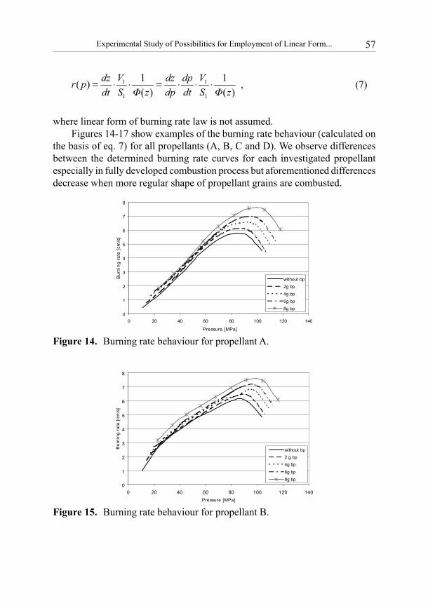
where linear form of burning rate law is not assumed. Figures 14-17 show examples of the burning rate behaviour (calculated on
the basis of eq. 7) for all propellants (A, B, C and D). We observe differences between the determined burning rate curves for each investigated propellant especially in fully developed combustion process but aforementioned differences decrease when more regular shape of propellant grains are combusted.
0
1
2
3
4
5
6
7
8
0 20 40 60 80 100 120 140
Pressure [MPa]
Bur
ning
rate
[cm
/s]
without bp2g bp4g bp6g bp8g bp
Figure 14. Burning rate behaviour for propellant A.
0
1
2
3
4
5
6
7
8
0 20 40 60 80 100 120 140Pressure [MPa]
Bur
ning
rat
e [c
m/s
]
without bp2 g bp4g bp
6g bp8g bp
Figure 15. Burning rate behaviour for propellant B.

58 Z.K. Leciejewski
0
1
2
3
4
5
6
7
8
9
0 20 40 60 80 100 120Pressure [MPa]
Burn
ing
rate
[cm
/s]
without bp2g bp4g bp6g bp8g bp
Figure 16. Burning rate behaviour for propellant C.
0
1
2
3
4
5
6
7
8
0 20 40 60 80 100 120 140Pressure [MPa]
Bur
ning
rat
e [c
m/s
]
without bp2g bp4g bp6g bp8g bp
Figure 17. Burning rate behaviour for propellant D.
Large tube grains (propellant C) and square plate grains (propellant D) are more regular geometrically, without the imperfections typical of fine-grained tube propellant (A) and ignition gases have easier (in contrast to propellant A) access to all surface of grain [11]. Real ignition process of propellant A (in the case of small mass of black powder particularly) does not meet theoretical assumptions but significant increase of black powder mass during closed vessel firings creates better and better conditions of ignition process becoming close to the theoretical model of propellant burning. It seems probably that the assumption that all propellant grains are ignited uniformly, with all exposed surface areas of the grains may be performed by a gaseous ignition system [12]. The ignition mixture (for example CH4-02) permits to treat ignition process of propellant according to presented above assumption and additionally permits to discriminate the combustion properties of two parts of the particles (in deterred propellants).

59Experimental Study of Possibilities for Employment of Linear Form...
Conclusions
The characteristic pressure-travel curve of a gun system is dependent upon many factors: variation in chemical composition of a propellant, ignition characteristics, propellant grain characteristics, loading conditions (charge weight variations), variations in burning rate of a propellant etc. The burning time of a propellant grain can be controlled by several means: the size and shape of the propellant grain, the number of perforations in each grain, the web thickness and the rate of burning of the grain. Ideally one would like to ignite all propellant grains at the same time.
Closed vessel tests are often conducted under conditions that are far different from those encountered in a gun system. Therefore extrapolation of formulated burning rate laws to a gun system usually yields poor results unless some adjustments are made. In the paper the linear form of burning rate law r=r1·p was reviewed. So far the coefficient r1 of the form has been treated (for a given propellant) as constant for total combustion process of all conventional propellants and linear form of burning rate law has been used in interior ballistics governing equations. The main conclusions following from this work are:1. Real ignition process of fine-grained propellant realised during closed
vessel tests, conducted under conditions that are far different from those encountered in a gun system, does not meet theoretical assumptions of propellant burning model.
2. The pressure impulse and dynamics of propellant burning not only depend on the size and shape of the propellant grains, the web thickness but depend also on ignition system and mass of igniter. Significant increase of black powder mass creates better and better conditions of ignition process becoming close to the theoretical model.
3. The differences in calculations of propellant burning rate indicate that there are limitations to the validity of the linear approach of burning rate law. The linear form of burning rate law with constant value of coefficient r1 should not be particularly used in ballistic calculations of gun systems with fine-grained propellants.
4. The linear form of burning rate law may be used rather for propellants with large, more regular geometrically grains and such ignition system that permit uniformly propellant ignition with all exposed surface areas of the grains. In this case the values of coefficient r1 may be similar for two different calculating methods (from total or limited impulse of pressure). Linearity of this form should be tested in advance (according to equation 6).

60 Z.K. Leciejewski
5. The influence of magnitude of the igniter mass charge on the time of ignition period and the form of burning rate in the first part of propellant combustion should be investigated and discussed. It will be next step of author’s analysis.
Acknowledgements
This paper presents some results of the Research Project 0 T00B 010 28 supported by Polish Ministry of Science and Higher Education in 2005-2007.
The author gratefully acknowledges the assistance of Mr Zbigniew Surma, Ballistics Laboratory Military University of Technology, in providing the measurement data presented here.
References
[1] Krier H., Summerfield M., Interior Ballistic of Guns, Volume 66 Progress in Astronautics and Aeronautics, Published by the American Institute of Aeronautics and Astronautics, New York 1979.
[2] Moss G.M., Leeming D.W., Farrer C.L., Military Ballistics – A Basic Manual, Royal Military College of Science, Shrivenham, Ed. Brassey’s (UK) Ltd, 1995.
[3] STANAG 4367 LAND (Edition 2) – Thermodynamic Interior Ballistic Model with Global Parameters, Military Agency for Standardization, Brussels 2000.
[4] Kadanka V., Internal Ballistics of Gun Systems (in Czech), Ed. Czech Ministry of Defence, Praha 1985.
[5] Sieriebriakov M., Internal Ballistics (in Russian), Ed. OBORONGIZ, Moscow 1949.
[6] Torecki S., Internal Ballistics, (in Polish), Ed. Military University of Technology, Warsaw 1980.
[7] Vasile T., Internal Ballistics of Gun Systems, (in Romanian), Ed. Technical Military Academy, Bucharest 1993.
[8] Krier H., Adams M.J., An Introduction to Gun Interior Ballistics and a Simplified Ballistic Code, Interior Ballistic of Guns, Volume 66 Progress in Astronautics and Aeronautics, The American Institute of Aeronautics and Astronautics, New York 1979, pp. 1-36.
[9] STANAG 4115 LAND (Edition 2) – Definition and Determination of Ballistic Properties of Gun Propellants, Military Agency for Standardization, Brussels, 1997.
[10] Leciejewski Z., Closed Vessel Tests: Part II - Temperature Factor Determination of Fine-Grained Propellant, Proc. VIth International Armament Conference SAAT’2006, Waplewo, Poland, 2006, pp. 632-637.

61Experimental Study of Possibilities for Employment of Linear Form...
[11] Leciejewski Z., Singularities of Burning Rate Determination of Fine-Grained Propellants, Proc. 23rd International Symposium on Ballistics, Volume I, Tarragona, Spain, 16-20 April, 2007, pp. 369-376.
[12] Jeunieau L., Lefebvre M.H., Papy A., Pirlot M.C., Guillaume P., Reynaud Ch., Closed Vessel Test: Influence of The Ignition Method on The Combustion Rate, Proc. 33rd International Annual Confernce of ICT, June 25, Karlsruhe, Germany, 2002.