Experimental Study and Numerical Model Calibration for ...
40
Experimental Study and Numerical Model Calibration for Earthquake-Induced Collapse of RC Frames with Emphasis on Key Columns, Joints, and the Overall Structure Author Xie, Linlin, Lu, Xinzheng, Guan, Hong, Lu, Xiao Published 2015 Journal Title Journal of Earthquake Engineering Version Accepted Manuscript (AM) DOI https://doi.org/10.1080/13632469.2015.1040897 Copyright Statement © 2015 Taylor & Francis (Routledge). This is an Accepted Manuscript of an article published by Taylor & Francis in Journal of Earthquake Engineering on 14 Aug 2015, available online: http:// www.tandfonline.com/10.1080/13632469.2015.1040897. Downloaded from http://hdl.handle.net/10072/125129 Griffith Research Online https://research-repository.griffith.edu.au
Transcript of Experimental Study and Numerical Model Calibration for ...

Experimental Study and Numerical Model Calibration forEarthquake-Induced Collapse of RC Frames with Emphasison Key Columns, Joints, and the Overall Structure
Author
Xie, Linlin, Lu, Xinzheng, Guan, Hong, Lu, Xiao
Published
2015
Journal Title
Journal of Earthquake Engineering
Version
Accepted Manuscript (AM)
DOI
https://doi.org/10.1080/13632469.2015.1040897
Copyright Statement
© 2015 Taylor & Francis (Routledge). This is an Accepted Manuscript of an article published byTaylor & Francis in Journal of Earthquake Engineering on 14 Aug 2015, available online: http://www.tandfonline.com/10.1080/13632469.2015.1040897.
Downloaded from
http://hdl.handle.net/10072/125129
Griffith Research Online
https://research-repository.griffith.edu.au
Xie LL, Lu XZ, Guan H, Lu X, Experimental study and numerical model calibration for earthquake-induced collapse of RC frames with emphasis on key columns, joints and overall structure. Journal of Earthquake Engineering, Accepted on Apr. 8,
2015. DOI: 10.1080/13632469.2015.1040897.
Experimental Study and Numerical Model Calibration for Earthquake-induced Collapse of RC Frames with Emphasis on Key Columns, Joints and the Overall
Structure
Linlin Xie1, Xinzheng Lu2, *, Hong Guan3, and Xiao Lu4
1 Department of Civil Engineering, Tsinghua University, Beijing, P.R. China
2 Department of Civil Engineering, Tsinghua University, Beijing, P.R. China
3 Griffith School of Engineering, Griffith University Gold Coast Campus, Queensland 4222,
Australia
4 Department of Civil Engineering, Beijing Jiaotong University, Beijing, P.R. China.
Abstract
A thorough investigation of earthquake-induced collapse of reinforced concrete frames is
presented. The inherent correlation between the nonlinear behavior of key components and
the collapse mechanism of overall frame is examined through concurrent collapse tests of
both frame and key components. Important issues in the component models are investigated
through calibration against experiments, leading to a comprehensive structural system model.
Both test and simulation indicate that the seismic performance are predominately governed by
the key columns, whereas the energy dissipation capacity is somewhat affected by the joints.
This study offers systematic experimental data and numerical models for future collapse
assessments.
*Address to correspondence to Xinzheng Lu, Department of Civil Engineering, Tsinghua University, Beijing, P.R. China. E-mail: [email protected]
Xie LL, Lu XZ, Guan H, Lu X, Experimental study and numerical model calibration for earthquake-induced collapse of RC frames with emphasis on key columns, joints and overall structure. Journal of Earthquake Engineering, Accepted on Apr. 8,
2015. DOI: 10.1080/13632469.2015.1040897. Keywords: Structural collapse; RC frame; Experimental calibration; Key components;
Joints.
1. Introduction
Reinforced concrete (RC) frame structures, being one of the most popular structural systems
for residential and commercial buildings, often experience severe damage and collapse when
subjected to destructive earthquakes (e.g., the Northridge earthquake in 1994, the Kobe
earthquake in 1995, the Chi-Chi earthquake in 1999 and the Wenchuan earthquake in 2008)
[Swinbanks, 1995; Otani, 1999; Wu et al., 2009; Lu et al., 2012]. In particular, as the most
devastating earthquake in China over the past three decades, the Wenchuan earthquake led to
the collapse of thousands of RC frames; the event killed 69,195 people and left 18,392
missing and amounted to about 136 billion US dollars losses
(http://en.wikipedia.org/wiki/2008_Sichuan_earthquake). Despite being designed following
the 2001 version of the Chinese Code for Seismic Design of Buildings (GB 50011-2001)
[CMC, 2001] (note that the same design code was revised after the Wenchuan earthquake
and subsequently released in 2010 [CMC, 2010a]), the majority of the frames still suffered
severe damages. For example, 29.2% of the RC frames in Beichuan City collapsed partially
and 33.3% collapsed completely [Civil and Structural Groups of Tsinghua University et al.,
2008]. Furthermore, the failure modes observed during the Wenchuan earthquake were
inconsistent with those expected. For example, many columns exhibited severe damage, even
failure, prior to the beams; and some beam-column joints also experienced different degrees
of damage. These phenomena appear to be contradictory to the “strong-column-weak-beam”
and “strong-joint-weak-member” principles expected by the Chinese codes [CMC, 2001,
2010a]. To further investigate the inherent collapse mechanisms of the RC frames damaged

Xie LL, Lu XZ, Guan H, Lu X, Experimental study and numerical model calibration for earthquake-induced collapse of RC frames with emphasis on key columns, joints and overall structure. Journal of Earthquake Engineering, Accepted on Apr. 8,
2015. DOI: 10.1080/13632469.2015.1040897. during the Wenchuan earthquake, both experiments and numerical simulation are considered
necessary to provide a reliable and effective means for damage assessments.
This study thus aims to perform both experimental and numerical investigations on the
inherent collapse mechanisms of RC frames and to identify some of the important research
challenges and issues. Numerous experimental studies, including static and shaking table
tests, have been conducted. These studies can be classified into two categories: at the
component level [Beres et al., 1996; Ghannoum and Moehle, 2012a; Elsouri and Harajli,
2013] and at the structural system level [Kabeyasawa et al., 2007; Wu et al., 2009; Moaveni
et al., 2010; Panagiotou et al., 2011]. Among these, experimental studies of the overall
structures are generally regarded as the most reliable method of investigation. This is because
collapse is a global structural behavior featuring a complicated internal force redistribution
characteristic during the collapse process. Despite the fact that the entire collapse process can
be observed in the structural system level experiments, detailed behavior (e.g., internal forces
and dissipated energies) of the individual structural components cannot be readily obtained.
Particularly, the correlation between the internal force, deformation, and energy dissipation
capacity of the key components and the collapse resistance of the overall structure is difficult
to be established. This fact, to some extent, limits (1) in-depth investigations of the inherent
collapse mechanisms; (2) identifications of the key components affecting the collapse of the
entire structure, (3) further improvements of the key component design, and (4) discussions
on the main source of computational errors of a numerical model when its simulation results
are inconsistent with the experimental data. Moreover, it has been noted that the damage
modes obtained in the experiments are different from the actual ones observed in the
Wenchuan earthquake. This is mainly attributed to the differences between the real-world
engineering practice and the test frames, including the tie beams, the slabs and other design

Xie LL, Lu XZ, Guan H, Lu X, Experimental study and numerical model calibration for earthquake-induced collapse of RC frames with emphasis on key columns, joints and overall structure. Journal of Earthquake Engineering, Accepted on Apr. 8,
2015. DOI: 10.1080/13632469.2015.1040897. details. However, such particular design details have rarely been considered concurrently in
an investigation.
With regard to the numerical simulation, research to date indicates that it has become
increasingly effective to examine the collapse mechanisms of RC frames [Elwood and
Moehle, 2008; Haselton, 2008; Haselton et al., 2009; Lynch et al., 2011; Ghannoum and
Moehle, 2012b; Kim et al., 2012]. Nevertheless, several critical issues related to the modeling
techniques for structural components and the overall system have been identified [Ibarra and
Krawinkler, 2005; Ibarra et al. 2005; Lignos and Krawinkler, 2011; Lignos and Krawinkler
2012]. Deierlein and his colleagues [Haselton, 2008; Haselton et al., 2009] indicated that
when simulating an earthquake-induced structural collapse, nonlinear behavior of all the
structural components must be comprehensively considered. Two critical challenges must
also be addressed for a rational and accurate simulation: (1) Advanced component models for
RC beams, columns and joints are necessary to capture the characteristic behavior of an RC
frame, from elastic to yield, and finally to collapse. (2) The key parameters of these models
must be calibrated based on the data from carefully designed experiments. To address these
challenges, a number of beam-column models [Spacone et al., 1996; Ibarra et al., 2005] and
joint models [Alath and Kunnath, 1995; Altoontash, 2004; Mitra and Lowes, 2007; Park and
Mosalam, 2013] have been proposed in recent decades. However, due to the complicated
nature of RC frames, without accurate calibrations using detailed experimental data, it is
rather difficult to identify the most appropriate component model capable of simulating the
collapse behavior accurately. Similarly, it is also hard to evaluate the critical parameters in
the models without a set of benchmarking experimental data. In consequence, in the absence
of the rational component models, the reliability of the prediction results at the structural
system level is also doubtful. Therefore, to evaluate the rationality of the component models
Xie LL, Lu XZ, Guan H, Lu X, Experimental study and numerical model calibration for earthquake-induced collapse of RC frames with emphasis on key columns, joints and overall structure. Journal of Earthquake Engineering, Accepted on Apr. 8,
2015. DOI: 10.1080/13632469.2015.1040897. and the corresponding structural model, as well as the accuracy of the prediction results and
the reliability of the conclusions drawn from the analysis, further experimental studies and
comprehensive model calibration based on available database [Panagiotakos and Fardis,
2001; Lignos and Krawinkler, 2012; Perus et al. 2014] are considered necessary and critical.
As described above, a carefully designed experimental program covering both the overall
frame and the key components is valuable for understanding the collapse mechanisms and
calibrating the numerical models of RC frames. Due to limited work on such experiments and
model calibration, the focus of this study is thus to perform a series of pseudo-static collapse
experiments and numerical model calibrations concurrently for both the key components and
the overall frame. Damage mechanisms of the RC frames exhibited in the Wenchuan
earthquake will also be thoroughly investigated. Specifically, four innovations of the
proposed experimental research are highlighted herein: (1) concurrent experiments on the key
components and the overall frame are performed to investigate the correlation between the
nonlinear behavior of the key components and the collapse mechanism of the structure; (2)
the loading condition and the detailed design parameters of the key components are assumed
to be identical to the corresponding components in the overall frame; (3) to better replicate
the real-world engineering practice, a tie beam is designed at the bottom of the column to
examine its constraint effect to the columns; (4) the frame beam is designed as a T-shaped
section to account for the contribution of slabs, and the flange width is set to be 6 times of the
slab thickness in accordance with the Chinese Concrete Design Code [CMC, 2002]. In the
proposed numerical simulation, the accuracy, stability and robustness of different numerical
component models and the associated material models are evaluated based on the detailed
experimental data. Consequently, the appropriate component models can then be
recommended. Based on these component models, a structural system model, considering all

Xie LL, Lu XZ, Guan H, Lu X, Experimental study and numerical model calibration for earthquake-induced collapse of RC frames with emphasis on key columns, joints and overall structure. Journal of Earthquake Engineering, Accepted on Apr. 8,
2015. DOI: 10.1080/13632469.2015.1040897. the possible nonlinear factors associated with the collapse of RC frames, is successfully
proposed to simulate the entire collapse process. The research outcome of this study will
provide an in-depth understanding of the inherent collapse mechanisms of similar RC frames
during strong earthquakes, and will also offer systematic experimental data and reference
numerical models for future collapse assessments of such structures.
2. Pseudo-Static Collapse Experiments
2.1. Design of Half-Scale Prototype
This research focused on the investigation of the collapse mechanisms of RC frames
damaged during the Wenchuan earthquake. The frames concerned were constructed in
accordance with the 2001 version of the Chinese Seismic Design Code [CMC, 2001]. A
prototype model, i.e. a 3-span 6-story RC frame, is herein designed following the Chinese
codes [CMC, 2001, 2002]. The prototype frame is located on a site with a seismic design
intensity of seven (the peak ground acceleration (PGA) is 200 cm/s2 for 10% probability of
exceedance in 50 years) and a site classification of II (i.e., an equivalent shear-wave velocity
of 360 m/s for 30 m soil (VS30)). The dimensions and design strengths of the prototype frame
are summarized in Table 1. The dead and live loads are 4.6 kN/m2 and 2.0 kN/m2,
respectively. According to the Chinese Code for Seismic Design of Buildings
(GB50011-2001) [CMC, 2001], the design axial load ratio calculated using Eq. (1) is found
to be approximately 0.8 for the middle column on the first story.
cc
LLDL
fLLDLn
γγγ
/+
= (1)
in which n is the design axial load ratio; DL and LL are respectively the dead load and live
load of the building for seismic design; γDL (= 1.2) and γDL (= 1.4) are the partial factors for

Xie LL, Lu XZ, Guan H, Lu X, Experimental study and numerical model calibration for earthquake-induced collapse of RC frames with emphasis on key columns, joints and overall structure. Journal of Earthquake Engineering, Accepted on Apr. 8,
2015. DOI: 10.1080/13632469.2015.1040897.
dead load and live load, respectively; fc is the concrete compressive strength; γc (= 1.4) is the
partial factor of concrete strength. Note that the actual axial load ratio without considering
the partial factors is approximately 0.395. The corresponding axial forces are approximately
1304 kN in the prototype and 326kN in the test frame, respectively. The PKPM [CABR,
2010] software is employed to perform reinforcement design.
TABLE 1: Dimensions and design strengths of the prototype frame Clear height of
the column Clear span of
the beam Cross sectional dimension Design strength
Columns Beams Concrete Longitudinal steel Stirrup
3.3 m 6 m 400 mm×400 mm
250 mm×500 mm 30 MPa 300 MPa 210 MPa
To better represent the behavior of the real structure, the size of the model is designed as
large as possible to make full use of the loading capacity of the testing equipment.
Considering the height limitation of the strong reaction wall in the laboratory, a half-scaled
model is adopted. Such scale is also used by other researchers [Elwood and Moehle, 2008].
The dimensions and reinforcement details of the scaled model are presented in Figure 1. The
load pattern of the experiment is illustrated in Figure 2(a), where the upper three stories are
simplified into four concentrated loads applied downward by two vertical actuators and two
load-distributing girders. Each actuator provides a 489 kN vertical load at the one-third point
of the corresponding load-distributing girder, which makes a 2:1 proportion of the axial
forces in the middle-columns (Columns 2 and 3) and those in the side-columns (Columns 1
and 4). Rollers, as shown in Figure 2, are installed to ensure that the vertical actuators could
translate horizontally together with the roof. The vertical loads provided by the actuators are
measured throughout the test. The maximum variation of the axial loads during the test is less
than 2% of the expected axial load, suggesting that the actuators are able to stably provide
constant vertical loads. The proportion of the designed seismic forces from the sixth to the
first story of the prototype is 6:5:4:3:2:1. Note that only the bottom three stories are tested,
Xie LL, Lu XZ, Guan H, Lu X, Experimental study and numerical model calibration for earthquake-induced collapse of RC frames with emphasis on key columns, joints and overall structure. Journal of Earthquake Engineering, Accepted on Apr. 8,
2015. DOI: 10.1080/13632469.2015.1040897. therefore all of the seismic forces sustained by the upper three stories are applied to the top of
the third story. Hence, three cyclic lateral loads with a proportion of 18:2:1 are applied by the
three horizontal actuators at the third, second and first story to conduct a cyclic static
experiment, as illustrated in Figure 2(a). Figure 2(b) shows the experimental setup of the
scaled frame. Four laterally restrained braces are used to limit the out-of-plane displacement
of the frame. The entire loading process is controlled by the displacement of the top floor,
and a mixed control test program is adopted to ensure the proportionality of three horizontal
loads. The lateral loading are selected in accordance with the protocols specified in the
Specification of Testing Methods for Earthquake Resistant Building (JGJ 101-96) [CMC,
1997], as shown in Figure 2(c).
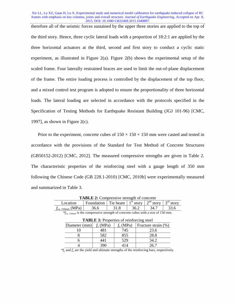
Prior to the experiment, concrete cubes of 150 × 150 × 150 mm were casted and tested in
accordance with the provisions of the Standard for Test Method of Concrete Structures
(GB50152-2012) [CMC, 2012]. The measured compressive strengths are given in Table 2.
The characteristic properties of the reinforcing steel with a gauge length of 350 mm
following the Chinese Code (GB 228.1-2010) [CMC, 2010b] were experimentally measured
and summarized in Table 3.
TABLE 2: Compressive strength of concrete Location Foundation Tie beam 1st story 2nd story 3rd story
fcu, 150mm (MPa) 36.6 31.8 36.2 34.7 33.6 *fcu, 150mm is the compressive strength of concrete cubes with a size of 150 mm.
TABLE 3: Properties of reinforcing steel Diameter (mm) fy (MPa) fu (MPa) Fracture strain (%)
10 481 745 23.6 8 582 855 28.8 6 441 529 34.2 4 390 414 26.7
*fy and fu are the yield and ultimate strengths of the reinforcing bars, respectively.

Xie LL, Lu XZ, Guan H, Lu X, Experimental study and numerical model calibration for earthquake-induced collapse of RC frames with emphasis on key columns, joints and overall structure. Journal of Earthquake Engineering, Accepted on Apr. 8,
2015. DOI: 10.1080/13632469.2015.1040897.
(a)
(b)

Xie LL, Lu XZ, Guan H, Lu X, Experimental study and numerical model calibration for earthquake-induced collapse of RC frames with emphasis on key columns, joints and overall structure. Journal of Earthquake Engineering, Accepted on Apr. 8,
2015. DOI: 10.1080/13632469.2015.1040897.
(c)
FIGURE 1: Dimensions and reinforcement details of the scaled frame: (a) frame, (b) beams/columns and (c) joints.
(a) (b)
(c)
FIGURE 2: Test setup of the overall frame: (a) load pattern of the experiment, (b) experimental setup
of the overall frame and (c) lateral loading protocol
2.2. Design of Half-Scale Key Components

Xie LL, Lu XZ, Guan H, Lu X, Experimental study and numerical model calibration for earthquake-induced collapse of RC frames with emphasis on key columns, joints and overall structure. Journal of Earthquake Engineering, Accepted on Apr. 8,
2015. DOI: 10.1080/13632469.2015.1040897. Damage modes observed in the Wenchuan earthquake and the preliminary numerical analysis
[Tang, 2011] prior to the proposed tests have both revealed two notable characteristics: (1)
the bottom of the columns on the first story exhibited severe damage, which may trigger the
collapse of the overall structure; (2) the beam-column joints on the first story also
experienced severe damage, which may affect the seismic performance of the overall
structure. In consequence, to investigate the inherent correlation between the nonlinear
behavior of these key structural components and the collapse mechanism of the overall
structure, four frame columns and two beam-column joints on the first story are selected for
the key component tests. These six specimens include two identical side columns, two
identical middle columns, one side joint and one middle joint, as indicated in Figure 3. Note
that the detailed design information of these components is identical to the corresponding
components in the overall frame. Furthermore, based on the actual compressive strengths, the
vertical loads applied to the key components are adjusted to ensure that the axial load ratios
are consistent with those of the corresponding components in the overall structural test (see
Table 4).
1-1 1-2 1-3 1-4
2-1 2-2 2-3 2-4
3-1 3-2 3-3 3-4
1 2 3 4
5 6 7 8
9 10 11 12
Side joint EMiddle joint F
Side column A&B
Middle column C&D
FIGURE 3: Locations of the selected key components
TABLE 4: Compressive strengths of concrete and axial forces for each specimen Specimen fcu, 150mm (MPa) Axial load (kN)
Side column A 31.1 141 Side column B 34.5 156
Middle column C 30.1 256
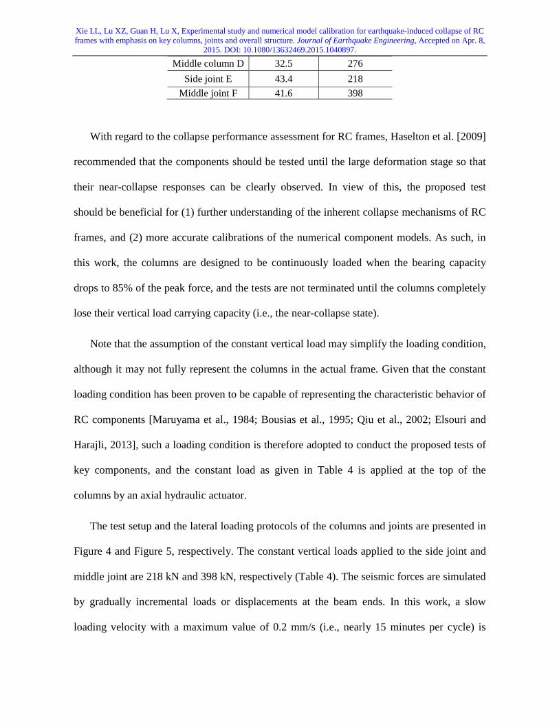
Xie LL, Lu XZ, Guan H, Lu X, Experimental study and numerical model calibration for earthquake-induced collapse of RC frames with emphasis on key columns, joints and overall structure. Journal of Earthquake Engineering, Accepted on Apr. 8,
2015. DOI: 10.1080/13632469.2015.1040897.
Middle column D 32.5 276 Side joint E 43.4 218
Middle joint F 41.6 398
With regard to the collapse performance assessment for RC frames, Haselton et al. [2009]
recommended that the components should be tested until the large deformation stage so that
their near-collapse responses can be clearly observed. In view of this, the proposed test
should be beneficial for (1) further understanding of the inherent collapse mechanisms of RC
frames, and (2) more accurate calibrations of the numerical component models. As such, in
this work, the columns are designed to be continuously loaded when the bearing capacity
drops to 85% of the peak force, and the tests are not terminated until the columns completely
lose their vertical load carrying capacity (i.e., the near-collapse state).
Note that the assumption of the constant vertical load may simplify the loading condition,
although it may not fully represent the columns in the actual frame. Given that the constant
loading condition has been proven to be capable of representing the characteristic behavior of
RC components [Maruyama et al., 1984; Bousias et al., 1995; Qiu et al., 2002; Elsouri and
Harajli, 2013], such a loading condition is therefore adopted to conduct the proposed tests of
key components, and the constant load as given in Table 4 is applied at the top of the
columns by an axial hydraulic actuator.
The test setup and the lateral loading protocols of the columns and joints are presented in
Figure 4 and Figure 5, respectively. The constant vertical loads applied to the side joint and
middle joint are 218 kN and 398 kN, respectively (Table 4). The seismic forces are simulated
by gradually incremental loads or displacements at the beam ends. In this work, a slow
loading velocity with a maximum value of 0.2 mm/s (i.e., nearly 15 minutes per cycle) is

Xie LL, Lu XZ, Guan H, Lu X, Experimental study and numerical model calibration for earthquake-induced collapse of RC frames with emphasis on key columns, joints and overall structure. Journal of Earthquake Engineering, Accepted on Apr. 8,
2015. DOI: 10.1080/13632469.2015.1040897. adopted to conduct the quasi-static tests. For such a slow loading velocity, the loading-rate
effect can be negligible [Ghannoum et al. 2012].
(a) (b)
(c) (d)
FIGURE 4: Test setup of the columns: (a) diagram of the experimental device, (b) photograph of the
experimental device, (c) lateral loading protocol of side columns and (d) lateral loading protocol of
middle columns
(a) (b)

Xie LL, Lu XZ, Guan H, Lu X, Experimental study and numerical model calibration for earthquake-induced collapse of RC frames with emphasis on key columns, joints and overall structure. Journal of Earthquake Engineering, Accepted on Apr. 8,
2015. DOI: 10.1080/13632469.2015.1040897.
South North
South North
(c) (d)
-120-90-60-30
0306090
120
0 7 14 21 28
Dis
plac
emen
t (m
m)
Loading cycle
-120-90-60-30
0306090
120
0 7 14 21 28D
ispl
acem
ent (
mm
)Loading cycle
(e) (f)
FIGURE 5: Test setup of the joints (mm): (a) diagram of the experimental device of Side joint E, (b) diagram of the experimental device of Middle joint F, (c) photograph of the experimental device of
Side joint E, (d) photograph of the experimental device of Middle joint F, (e) vertical loading protocol of Side joint E and (f) vertical loading protocol of Middle joint F
3. Test Observations and Analysis of the Experimental Data
For the overall frame test, diagonal cracks (point A in Figure 6) appeared at the middle joints
of the first story when the displacement of the top floor reached 33 mm. When the frame
experienced a drift ratio of 2% (i.e., when the peak displacement of the top floor reached 84
mm), which is the maximum allowable drift ratio specified in the Chinese seismic design
code [CMC, 2001] for RC frames, concrete crushing was obvious at the bottom of the side
and middle columns, and concrete peeling took place at the joints (point B in Figure 6).
When the frame experienced a peak drift ratio of 3.85% (i.e., when the peak displacement of
the top floor reached 139 mm), severe concrete spalling was noticed on the cover layer at the

Xie LL, Lu XZ, Guan H, Lu X, Experimental study and numerical model calibration for earthquake-induced collapse of RC frames with emphasis on key columns, joints and overall structure. Journal of Earthquake Engineering, Accepted on Apr. 8,
2015. DOI: 10.1080/13632469.2015.1040897. bottom of Column 1-3 (point C in Figure 6). Finally, when the peak displacement of the top
floor reached 190 mm, the bottom of Column 1-3 experienced a large vertical deformation
(point D in Figure 6) and concrete at the bottom of the column completely crushed. At this
stage, the vertical loads applied to the top floor could no longer be maintained. Consequently,
the overall structure reached the collapse state. The base shear force-top displacement
hysteretic curve and the photos of each key state (points A, B, C and D) are presented in
Figure 6.
-210
-140
-70
0
70
140
210
-240 -160 -80 0 80 160 240
Load
/kN
Disp./mm
FrameA
A
B
B
C C
DD
E
E (Final collapse state)
Joint 3
Joint 3
Column 1- 3
Column 1- 3
Column 1- 3
FIGURE 6: Base shear force-top displacement hysteretic curve and damage states of the overall
frame
Based on the above-mentioned experimental observations, the following conclusions can
be drawn:
1. The bottom of the columns on the first story experienced the most severe damage.
2. The joints on the first story exhibited severe damage, while those on the second story
experienced different degrees of damage.

Xie LL, Lu XZ, Guan H, Lu X, Experimental study and numerical model calibration for earthquake-induced collapse of RC frames with emphasis on key columns, joints and overall structure. Journal of Earthquake Engineering, Accepted on Apr. 8,
2015. DOI: 10.1080/13632469.2015.1040897. 3. The response of the overall structure exhibited a significant shear deformation mode,
which could be observed from Figure 7. Such a deformation was dominated by the
inter-story drift ratio of the first story, and this phenomenon became more obvious
with increased peak displacement.
0
1
2
3
0 1 2 3 4 5 6 7
Stor
y
Maximum inter-drift ratio/%
FIGURE 7: Maximum inter-story drift ratio of each loading cycle
Ultimately, the loss of vertical load carrying capacity of Column 1-3, which was triggered
by the complete crushing of the column bottom, initiated the collapse of the overall frame.
Specifically for the key columns, when the side and middle columns experienced drift
ratios of 5.7% and 5.56%, respectively (i.e., when the top displacement of the columns
reached 60 mm and 57 mm), their lateral load carrying capacity were completely lost. In
addition, these columns were no longer capable of maintaining the vertical load due to the
P-∆ effect, thus leading to the collapse of these columns. The failure modes of the key
columns are consistent with those observed in the overall frame test. The lateral
load-displacement relation curves of the two side columns (A and B) and the two middle
columns (C and D) are presented together in Figures 8(a) and (b), respectively. Due to the
similarity of the failure phenomena of the two side (middle) columns, only two photos are
presented in Figure 8 for Side column B and Middle column D. It can be found from the

Xie LL, Lu XZ, Guan H, Lu X, Experimental study and numerical model calibration for earthquake-induced collapse of RC frames with emphasis on key columns, joints and overall structure. Journal of Earthquake Engineering, Accepted on Apr. 8,
2015. DOI: 10.1080/13632469.2015.1040897. figure that the middle columns reach a slightly higher peak load but a lower ductility in
comparison with the side columns. This is because the middle columns are designed with a
higher reinforcement ratio and a larger axial compression ratio.
-60
-40
-20
0
20
40
60
-80 -60 -40 -20 0 20 40 60 80
Load
/kN
Disp./mm
A B
Final state
-60
-40
-20
0
20
40
60
-80 -60 -40 -20 0 20 40 60 80
Load
/kN
Disp./mm
C D
Final state
(a) (b)
FIGURE 8: Lateral load-displacement relation and failure phenomena of (a) side columns and (b) middle columns
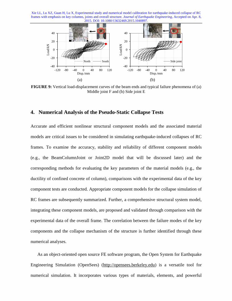
With regard to the key joints, both the side and middle joints experienced severe damage.
The joint cores exhibited numerous intersecting cracks, and complete concrete cover spalling
together with stirrup exposure. When the actuators reached their maximum capacities, the
experiment was terminated. The vertical load-displacement curves and the typical failure
phenomena are plotted in Figure 9. Note that the Middle joint F has two beam ends (i.e., the
north and south ends as shown in Figure 5(d)), and their vertical load-displacement curves
are presented in Figure 9(a). Figure 9(b) plots the same for the Side joint E. The key joint
tests indicate that the damage of the joints is much severer than that of the adjacent beams
and columns. This phenomenon is consistent with the damage mode observed in the overall
frame test, further validating that the expected “strong-joint-weak-member” failure mode
cannot be attained.
Xie LL, Lu XZ, Guan H, Lu X, Experimental study and numerical model calibration for earthquake-induced collapse of RC frames with emphasis on key columns, joints and overall structure. Journal of Earthquake Engineering, Accepted on Apr. 8,
2015. DOI: 10.1080/13632469.2015.1040897.
-40
-20
0
20
40
-120 -80 -40 0 40 80 120
Load
/kN
Disp./mm
North South
-40
-20
0
20
40
-120 -80 -40 0 40 80 120
Load
/kN
Disp./mm
Side joint
(a) (b)
FIGURE 9: Vertical load-displacement curves of the beam ends and typical failure phenomena of (a) Middle joint F and (b) Side joint E
4. Numerical Analysis of the Pseudo-Static Collapse Tests
Accurate and efficient nonlinear structural component models and the associated material
models are critical issues to be considered in simulating earthquake-induced collapses of RC
frames. To examine the accuracy, stability and reliability of different component models
(e.g., the BeamColumnJoint or Joint2D model that will be discussed later) and the
corresponding methods for evaluating the key parameters of the material models (e.g., the
ductility of confined concrete of column), comparisons with the experimental data of the key
component tests are conducted. Appropriate component models for the collapse simulation of
RC frames are subsequently summarized. Further, a comprehensive structural system model,
integrating these component models, are proposed and validated through comparison with the
experimental data of the overall frame. The correlation between the failure modes of the key
components and the collapse mechanism of the structure is further identified through these
numerical analyses.
As an object-oriented open source FE software program, the Open System for Earthquake
Engineering Simulation (OpenSees) (http://opensees.berkeley.edu) is a versatile tool for
numerical simulation. It incorporates various types of materials, elements, and powerful

Xie LL, Lu XZ, Guan H, Lu X, Experimental study and numerical model calibration for earthquake-induced collapse of RC frames with emphasis on key columns, joints and overall structure. Journal of Earthquake Engineering, Accepted on Apr. 8,
2015. DOI: 10.1080/13632469.2015.1040897. algorithms, thus allowing flexible definition of the numerical models satisfying specific
requirements of different research projects. OpenSees has also become increasingly popular,
being as one of the most influential platforms for nonlinear seismic analyses of various types
of structures [Elwood and Moehle, 2008; Haselton, 2008; Haselton et al., 2009; Lignos et al.,
2011a]. Because of these advantages, OpenSees is adopted in this study to conduct the
collapse assessment of RC frames.
4.1. Model Calibration for RC Columns
The Wenchuan earthquake and the overall frame test both indicate that the columns in RC
frames mostly exhibit a flexural-dominated failure mode. To simulate such a failure mode,
various finite element models have been proposed. These include the fiber beam model
[Spacone et al., 1996; Tram and Kasai, 2011] and the lumped plasticity model [Ibarra et al.,
2005; Lignos et al., 2011b; Lignos et al., 2013]. Through a regression analysis of 255 RC
column elements with different design and detailing characteristics, a strategy for selecting
the key parameters for a typical lumped plasticity model (i.e. the modified
Ibarra-Medina-Krawinkler deterioration model) [Ibarra et al., 2005] was proposed by
Deierlein and his colleagues [Haselton, 2008; Haselton et al., 2009]. This lumped plasticity
model was then used for the collapse simulation and assessment of a 3-span 4-story plane RC
frame [Haselton, 2008; Haselton et al., 2009]. Nevertheless, this model is incapable of taking
into account biaxial bending and the variation of axial forces. As an alternative, the fiber
beam model can capture the coupled biaxial bending/axial force behavior [Spacone et al.,
1996]. As such, the fiber beam model is adopted herein to simulate the key columns. It
should be noted that further validation is required to confirm the capacity of the fiber beam
model in simulating the collapse behavior of RC frames, as suggested by Haselton et al.
[2009]. Specifically, it is well acknowledged that the plastic deformation capacity of RC
Xie LL, Lu XZ, Guan H, Lu X, Experimental study and numerical model calibration for earthquake-induced collapse of RC frames with emphasis on key columns, joints and overall structure. Journal of Earthquake Engineering, Accepted on Apr. 8,
2015. DOI: 10.1080/13632469.2015.1040897. columns can be effectively improved by considering the confinement effect of the stirrups
[Mander et al., 1988; Légeron et al., 2005; Lu et al., 2013]. Despite numerous
stirrup-confined concrete models are available, further validation against the experimental
data is required to determine the most appropriate model for simulating RC columns and
frames at the near-collapse state [Haselton et al., 2009]. Moreover, the capacity of the
existing large deformation algorithms must also be further validated at the near-collapse
state.
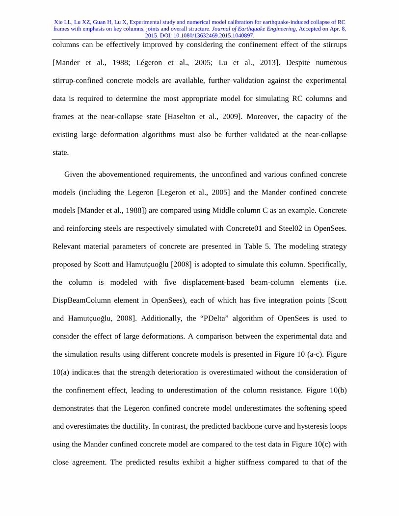
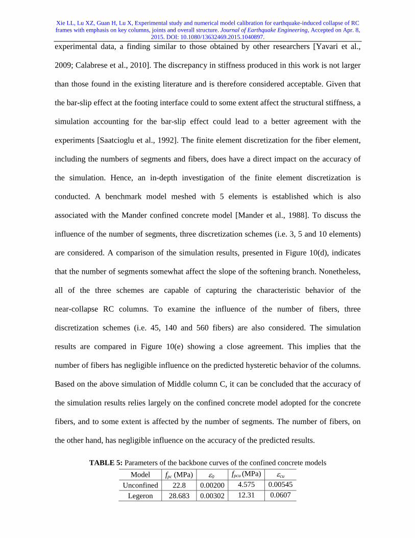
Given the abovementioned requirements, the unconfined and various confined concrete
models (including the Legeron [Legeron et al., 2005] and the Mander confined concrete
models [Mander et al., 1988]) are compared using Middle column C as an example. Concrete
and reinforcing steels are respectively simulated with Concrete01 and Steel02 in OpenSees.
Relevant material parameters of concrete are presented in Table 5. The modeling strategy
proposed by Scott and Hamutçuoğlu [2008] is adopted to simulate this column. Specifically,
the column is modeled with five displacement-based beam-column elements (i.e.
DispBeamColumn element in OpenSees), each of which has five integration points [Scott
and Hamutçuoğlu, 2008]. Additionally, the “PDelta” algorithm of OpenSees is used to
consider the effect of large deformations. A comparison between the experimental data and
the simulation results using different concrete models is presented in Figure 10 (a-c). Figure
10(a) indicates that the strength deterioration is overestimated without the consideration of
the confinement effect, leading to underestimation of the column resistance. Figure 10(b)
demonstrates that the Legeron confined concrete model underestimates the softening speed
and overestimates the ductility. In contrast, the predicted backbone curve and hysteresis loops
using the Mander confined concrete model are compared to the test data in Figure 10(c) with
close agreement. The predicted results exhibit a higher stiffness compared to that of the
Xie LL, Lu XZ, Guan H, Lu X, Experimental study and numerical model calibration for earthquake-induced collapse of RC frames with emphasis on key columns, joints and overall structure. Journal of Earthquake Engineering, Accepted on Apr. 8,
2015. DOI: 10.1080/13632469.2015.1040897. experimental data, a finding similar to those obtained by other researchers [Yavari et al.,
2009; Calabrese et al., 2010]. The discrepancy in stiffness produced in this work is not larger
than those found in the existing literature and is therefore considered acceptable. Given that
the bar-slip effect at the footing interface could to some extent affect the structural stiffness, a
simulation accounting for the bar-slip effect could lead to a better agreement with the
experiments [Saatcioglu et al., 1992]. The finite element discretization for the fiber element,
including the numbers of segments and fibers, does have a direct impact on the accuracy of
the simulation. Hence, an in-depth investigation of the finite element discretization is
conducted. A benchmark model meshed with 5 elements is established which is also
associated with the Mander confined concrete model [Mander et al., 1988]. To discuss the
influence of the number of segments, three discretization schemes (i.e. 3, 5 and 10 elements)
are considered. A comparison of the simulation results, presented in Figure 10(d), indicates
that the number of segments somewhat affect the slope of the softening branch. Nonetheless,
all of the three schemes are capable of capturing the characteristic behavior of the
near-collapse RC columns. To examine the influence of the number of fibers, three
discretization schemes (i.e. 45, 140 and 560 fibers) are also considered. The simulation
results are compared in Figure 10(e) showing a close agreement. This implies that the
number of fibers has negligible influence on the predicted hysteretic behavior of the columns.
Based on the above simulation of Middle column C, it can be concluded that the accuracy of
the simulation results relies largely on the confined concrete model adopted for the concrete
fibers, and to some extent is affected by the number of segments. The number of fibers, on
the other hand, has negligible influence on the accuracy of the predicted results.
TABLE 5: Parameters of the backbone curves of the confined concrete models Model fpc (MPa) ε0 fpcu (MPa) εcu
Unconfined 22.8 0.00200 4.575 0.00545 Legeron 28.683 0.00302 12.31 0.0607
Xie LL, Lu XZ, Guan H, Lu X, Experimental study and numerical model calibration for earthquake-induced collapse of RC frames with emphasis on key columns, joints and overall structure. Journal of Earthquake Engineering, Accepted on Apr. 8,
2015. DOI: 10.1080/13632469.2015.1040897.
Mander 28.692 0.00298 5.738 0.02907
-60
-40
-20
0
20
40
60
-80 -60 -40 -20 0 20 40 60 80
Load
/kN
Disp./mmTest Simulated
-60
-40
-20
0
20
40
60
-80 -60 -40 -20 0 20 40 60 80
Load
/kN
Disp./mmTest Simulated
(a) (b)
-60
-40
-20
0
20
40
60
-80 -60 -40 -20 0 20 40 60 80
Load
/kN
Disp./mmTest Simulated
-60
-40
-20
0
20
40
60
-80 -60 -40 -20 0 20 40 60 80
Load
/kN
Disp./mm3 ele. 5 ele. 10 ele.
(c) (d)
-60
-40
-20
0
20
40
60
-80 -60 -40 -20 0 20 40 60 80
Load
/kN
Disp./mm45 140 560
(e) FIGURE 10: Comparison of the hysteretic curves of Middle column C using (a) unconfined concrete
model, (b) Legeron model, (c) Mander model, (d) Mander model with different number of segments
and (e) Mander model with different number of fibers
Based on this validation, the Mander confined concrete model is adopted to simulate all
of the key columns. The comparisons between the experimental data and simulation results
are presented in Figure 11. Good agreements are also achieved for all these columns. This

Xie LL, Lu XZ, Guan H, Lu X, Experimental study and numerical model calibration for earthquake-induced collapse of RC frames with emphasis on key columns, joints and overall structure. Journal of Earthquake Engineering, Accepted on Apr. 8,
2015. DOI: 10.1080/13632469.2015.1040897. outcome confirms that the strength deterioration observed in the tests can be well captured
using the fiber beam model. The backbone curve and the hysteretic behavior are also proven
to agree well with the experimental data, thus conclusively validating the reliability of the
fiber beam model in simulating the near-collapse RC columns dominated by the flexural
behavior.
-60
-40
-20
0
20
40
60
-80 -60 -40 -20 0 20 40 60 80
Load
/kN
Disp./mmTest Simulated
-60
-40
-20
0
20
40
60
-80 -60 -40 -20 0 20 40 60 80Lo
ad/k
NDisp./mm
Test Simulated (a) (b)
-60
-40
-20
0
20
40
60
-80 -60 -40 -20 0 20 40 60 80
Load
/kN
Disp./mmTest Simulated
(c) FIGURE 11: Comparison of the hysteretic curves of (a) Side column A, (b) Side column B and (c)
Middle column D using Mander confined concrete model
4.2. Model Calibration for Beam-Column Joints
Despite being designed following the principle of “strong-joint-weak-member” according to
the Chinese seismic design code [CMC 2001], the Wenchuan earthquake destruction and
laboratory tests both indicate that the joints exhibited severe damage. In consequence, the
nonlinear behaviors of the joints are required to be considered in the collapse simulation and
assessment of RC frames. Although various joint models have been proposed to date [Alath

Xie LL, Lu XZ, Guan H, Lu X, Experimental study and numerical model calibration for earthquake-induced collapse of RC frames with emphasis on key columns, joints and overall structure. Journal of Earthquake Engineering, Accepted on Apr. 8,
2015. DOI: 10.1080/13632469.2015.1040897. and Kunnath, 1995; Altoontash, 2004; Mitra and Lowes, 2007], validation against the
experimental data is desirable to determine the most appropriate model for the simulation of
RC joints, in terms of the accuracy, stability and reliability. Furthermore, an appropriate joint
model should be capable of simulating three possible failure modes in numerical analyses
[Altoontash, 2004; Mitra and Lowes, 2007]. These failure modes are (1) shear failure of the
joint core, (2) anchorage failure of the frame-member longitudinal reinforcement embedded
in the joint, and (3) shear-transfer failure at the joint-beam and joint-column interfaces.
Subsequently, different joint models and the associated material models are calibrated based
on the experimental data of the key joints obtained earlier in this study. In addition to
evaluating an appropriate joint model, this study also lays a foundation for further
investigations of the influence of joint damage on the global deformation and the collapse
resistance of the overall frame.
4.2.1. Numerical models for RC joints
The joint models proposed over the last four decades can be divided into two categories.
The first category of the model uses a single nonlinear spring to represent all the potential
failure modes of the joints [Alath and Kunnath, 1995; Park and Mosalam, 2013]. An obvious
drawback of this model is that calibration of the parameters of the nonlinear spring is rather
difficult, considering the various failure modes of different joints. The second category
comprises a set of springs that respectively represent the abovementioned three types of
failure modes, viz. (1) the shear-panel springs to simulate the shear failure of the joint core,
(2) the bar-slip springs to simulate the anchorage failure of frame-member longitudinal
reinforcement, and (3) the interface-shear springs to simulate the shear-transfer failure at the
joint-beam and joint-column interfaces [Altoontash, 2004; Mitra and Lowes, 2007]. Having
different types of springs for different failure modes instead of a single spring for all the
Xie LL, Lu XZ, Guan H, Lu X, Experimental study and numerical model calibration for earthquake-induced collapse of RC frames with emphasis on key columns, joints and overall structure. Journal of Earthquake Engineering, Accepted on Apr. 8,
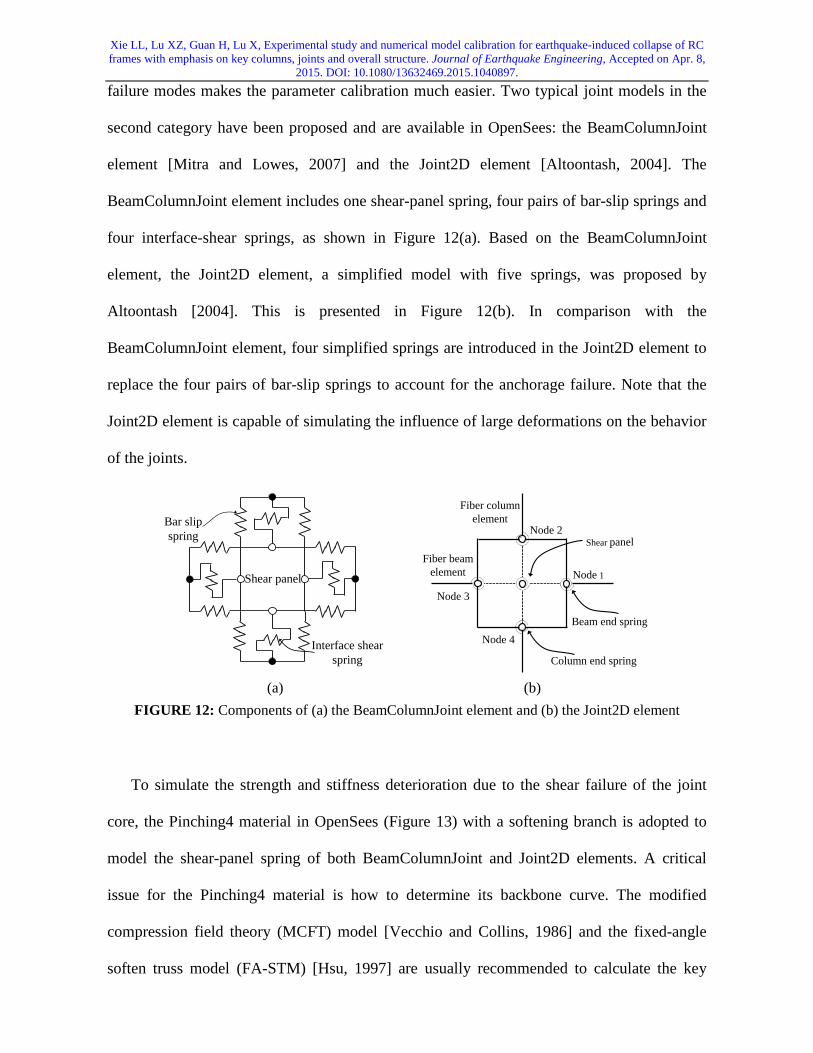
2015. DOI: 10.1080/13632469.2015.1040897. failure modes makes the parameter calibration much easier. Two typical joint models in the
second category have been proposed and are available in OpenSees: the BeamColumnJoint
element [Mitra and Lowes, 2007] and the Joint2D element [Altoontash, 2004]. The
BeamColumnJoint element includes one shear-panel spring, four pairs of bar-slip springs and
four interface-shear springs, as shown in Figure 12(a). Based on the BeamColumnJoint
element, the Joint2D element, a simplified model with five springs, was proposed by
Altoontash [2004]. This is presented in Figure 12(b). In comparison with the
BeamColumnJoint element, four simplified springs are introduced in the Joint2D element to
replace the four pairs of bar-slip springs to account for the anchorage failure. Note that the
Joint2D element is capable of simulating the influence of large deformations on the behavior
of the joints.
Shear panel
Bar slip spring
Interface shear spring
Shear panelFiber beam
element
Fiber column element
Beam end spring
Column end spring
Node 1
Node 2
Node 3
Node 4
(a) (b)
FIGURE 12: Components of (a) the BeamColumnJoint element and (b) the Joint2D element
To simulate the strength and stiffness deterioration due to the shear failure of the joint
core, the Pinching4 material in OpenSees (Figure 13) with a softening branch is adopted to
model the shear-panel spring of both BeamColumnJoint and Joint2D elements. A critical
issue for the Pinching4 material is how to determine its backbone curve. The modified
compression field theory (MCFT) model [Vecchio and Collins, 1986] and the fixed-angle
soften truss model (FA-STM) [Hsu, 1997] are usually recommended to calculate the key

Xie LL, Lu XZ, Guan H, Lu X, Experimental study and numerical model calibration for earthquake-induced collapse of RC frames with emphasis on key columns, joints and overall structure. Journal of Earthquake Engineering, Accepted on Apr. 8,
2015. DOI: 10.1080/13632469.2015.1040897. parameters of this curve, and the hysteretic rules associated with the strength and stiffness
deterioration proposed by Stevens et al. [1991] are adopted to represent the response under
cyclic loading. The other types of springs in the BeamColumnJoint and Joint2D elements are
simulated using the modeling approaches proposed by Mitra and Lowes [2007] and
Altoontash [2004], respectively.
Backbone curve
Hysteretic rule
Deformation
Load
12 3
4
FIGURE 13: Hysteretic model for the Pinching4 material
4.2.2. Model evaluation and verification
To investigate the influence of the nonlinear response of the joint, only the fiber beam
model is adopted herein to simulate Side joint E, as shown in Figure 14(a). This implies that
the joint zone is rigid and its nonlinear behavior is neglected. The simulation results are
compared in Figure 14(b) with the experimental data, where a significant discrepancy is
observed. This is because without consideration of the nonlinear behavior of the joint, the
predicted failure mode is a flexural failure at the ends of the beams and columns. This is
unlike the shear failure mode within the joint core as observed during the test. As such, the
nonlinear behavior of the joint must not be neglected in seismic performance assessments of
such a specimen.

Xie LL, Lu XZ, Guan H, Lu X, Experimental study and numerical model calibration for earthquake-induced collapse of RC frames with emphasis on key columns, joints and overall structure. Journal of Earthquake Engineering, Accepted on Apr. 8,
2015. DOI: 10.1080/13632469.2015.1040897.
Fiber beam element
T-shaped section
Fibe
r bea
m e
lem
ent
Rigid zone
Cyclic load+ : downward- : upward
-45
-30
-15
0
15
30
45
-150 -100 -50 0 50 100 150
Load
/kN
Disp./mmTest Simulated
(a) (b) FIGURE 14: Simulation of Side joint E without considering nonlinear effect of the joint: (a) FE
model system and (b) comparison between the experimental data and simulation results
An integrated model encompassing the fiber beam model and the joint model,
respectively for the beams/columns and the joints, is proposed to simulate the key joints. The
abovementioned two elements (i.e., the BeamColumnJoint and Joint2D elements are adopted
for each joint model, and two material models (i.e., the MCFT model and FA-STM) are used
to evaluate the envelopes of the shear stress-strain of the shear-panel spring. Of the four
combinations of the two elements and two material models, the most suitable combination for
simulating the behavior of the joints and the overall RC frame needs to be identified. This is
achieved by calculating the stress and strain at four key points on the shear stress-strain curve
of the shear-panel spring, as indicated in Figure 13. The calculated values using the MCFT
model and FA-STM are presented in Table 6. To compare the accuracy, reliability and
robustness of different models, identical numerical solution parameters, including the
maximum iterative steps and the tolerance of errors are adopted for all of the numerical
simulations.
TABLE 6: Parameters of the backbone curves of the shear panel spring
Specimen Model Point 1 Point 2 Point 3 Point 4
Middle joint F MCFT Strain 0.000209 0.00449 0.00738 0.0243 Stress (MPa) 1.544 7.06 7.93 0.00793
Xie LL, Lu XZ, Guan H, Lu X, Experimental study and numerical model calibration for earthquake-induced collapse of RC frames with emphasis on key columns, joints and overall structure. Journal of Earthquake Engineering, Accepted on Apr. 8,
2015. DOI: 10.1080/13632469.2015.1040897.
FA-STM Strain 0.0002 0.0048 0.0069 0.0146 Stress (MPa) 1.567 6.837 7.7121 3.7745
Side joint E MCFT Strain 0.000121 0.00422 0.0082 0.03536
Stress (MPa) 1.45 6 7.05 0.00705
FA-STM Strain 0.000143 0.0042 0.0055 0.0152 Stress (MPa) 1.4756 5.668 7.0031 3.9025
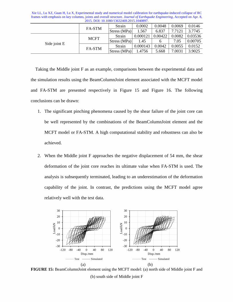
Taking the Middle joint F as an example, comparisons between the experimental data and
the simulation results using the BeamColumnJoint element associated with the MCFT model
and FA-STM are presented respectively in Figure 15 and Figure 16. The following
conclusions can be drawn:
1. The significant pinching phenomena caused by the shear failure of the joint core can
be well represented by the combinations of the BeamColumnJoint element and the
MCFT model or FA-STM. A high computational stability and robustness can also be
achieved.
2. When the Middle joint F approaches the negative displacement of 54 mm, the shear
deformation of the joint core reaches its ultimate value when FA-STM is used. The
analysis is subsequently terminated, leading to an underestimation of the deformation
capability of the joint. In contrast, the predictions using the MCFT model agree
relatively well with the test data.
-30
-20
-10
0
10
20
30
-120 -80 -40 0 40 80 120
Load
/kN
Disp./mmTest Simulated
-30
-20
-10
0
10
20
30
-120 -80 -40 0 40 80 120
Load
/kN
Disp./mmTest Simulated
(a) (b) FIGURE 15: BeamColumnJoint element using the MCFT model: (a) north side of Middle joint F and
(b) south side of Middle joint F

Xie LL, Lu XZ, Guan H, Lu X, Experimental study and numerical model calibration for earthquake-induced collapse of RC frames with emphasis on key columns, joints and overall structure. Journal of Earthquake Engineering, Accepted on Apr. 8,
2015. DOI: 10.1080/13632469.2015.1040897.
-30
-20
-10
0
10
20
30
-120 -80 -40 0 40 80 120
Load
/kN
Disp./mmTest Simulated
-30
-20
-10
0
10
20
30
-120 -80 -40 0 40 80 120
Load
/kN
Disp./mmTest Simulated
(a) (b) FIGURE 16: BeamColumnJoint element using the FA-STM model: (a) north side of Middle joint F
and (b) south side of Middle joint F
Given that the MCFT model performs better than FA-STM, a comparison between the
experimental data and the simulation results using the Joint2D element associated with the
MCFT model only is presented in Figure 17. Due to the fact that the large deformation
algorithm is implemented in the Joint2D element, the strength deterioration experienced in
the test can be well simulated when the negative displacement is larger than 60 mm.
Nevertheless, the hysteretic behaviors predicted by the Joint2D element differ a lot from the
test. Furthermore, the Joint2D element is proven to be relatively unstable, and a numerical
convergence is difficult to be achieved for this middle joint specimen.
-30
-20
-10
0
10
20
30
-120 -80 -40 0 40 80 120
Load
/kN
Disp./mmTest Simulated
-30
-20
-10
0
10
20
30
-120 -80 -40 0 40 80 120
Load
/kN
Disp./mmTest Simulated
(a) (b) FIGURE 17: Joint2D element using the MCFT model: (a) north side of Middle joint F and (b) south
side of Middle joint F
Xie LL, Lu XZ, Guan H, Lu X, Experimental study and numerical model calibration for earthquake-induced collapse of RC frames with emphasis on key columns, joints and overall structure. Journal of Earthquake Engineering, Accepted on Apr. 8,
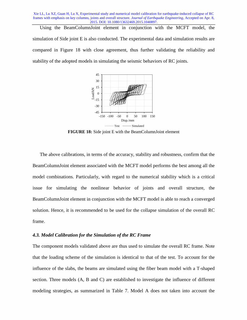
2015. DOI: 10.1080/13632469.2015.1040897. Using the BeamColumnJoint element in conjunction with the MCFT model, the
simulation of Side joint E is also conducted. The experimental data and simulation results are
compared in Figure 18 with close agreement, thus further validating the reliability and
stability of the adopted models in simulating the seismic behaviors of RC joints.
-45
-30
-15
0
15
30
45
-150 -100 -50 0 50 100 150
Load
/kN
Disp./mmTest Simulated
FIGURE 18: Side joint E with the BeamColumnJoint element
The above calibrations, in terms of the accuracy, stability and robustness, confirm that the
BeamColumnJoint element associated with the MCFT model performs the best among all the
model combinations. Particularly, with regard to the numerical stability which is a critical
issue for simulating the nonlinear behavior of joints and overall structure, the
BeamColumnJoint element in conjunction with the MCFT model is able to reach a converged
solution. Hence, it is recommended to be used for the collapse simulation of the overall RC
frame.
4.3. Model Calibration for the Simulation of the RC Frame
The component models validated above are thus used to simulate the overall RC frame. Note
that the loading scheme of the simulation is identical to that of the test. To account for the
influence of the slabs, the beams are simulated using the fiber beam model with a T-shaped
section. Three models (A, B and C) are established to investigate the influence of different
modeling strategies, as summarized in Table 7. Model A does not taken into account the
Xie LL, Lu XZ, Guan H, Lu X, Experimental study and numerical model calibration for earthquake-induced collapse of RC frames with emphasis on key columns, joints and overall structure. Journal of Earthquake Engineering, Accepted on Apr. 8,
2015. DOI: 10.1080/13632469.2015.1040897. confinement effect of concrete and the nonlinear behavior of joints. Model B considers the
confinement effect only using the Mander confined concrete model. Model C is a
comprehensive structural system model, integrating the fiber beam elements with the Mander
confined concrete model and the BeamColumnJoint elements associated with the MCFT
model.
TABLE 7: Case study Models Confined concrete model Model for joint
Model A Not considered Not considered Model B Mander Not considered Model C Mander BeamColumnJoint element
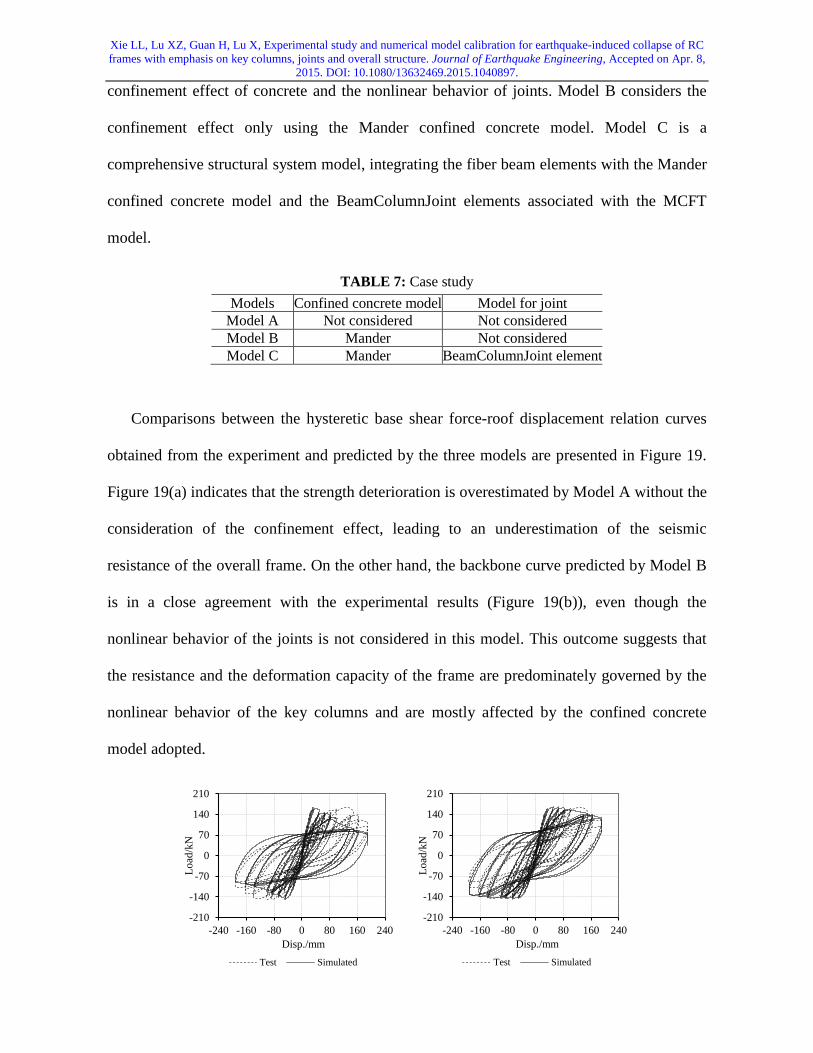
Comparisons between the hysteretic base shear force-roof displacement relation curves
obtained from the experiment and predicted by the three models are presented in Figure 19.
Figure 19(a) indicates that the strength deterioration is overestimated by Model A without the
consideration of the confinement effect, leading to an underestimation of the seismic
resistance of the overall frame. On the other hand, the backbone curve predicted by Model B
is in a close agreement with the experimental results (Figure 19(b)), even though the
nonlinear behavior of the joints is not considered in this model. This outcome suggests that
the resistance and the deformation capacity of the frame are predominately governed by the
nonlinear behavior of the key columns and are mostly affected by the confined concrete
model adopted.
-210
-140
-70
0
70
140
210
-240 -160 -80 0 80 160 240
Load
/kN
Disp./mmTest Simulated
-210
-140
-70
0
70
140
210
-240 -160 -80 0 80 160 240
Load
/kN
Disp./mmTest Simulated

Xie LL, Lu XZ, Guan H, Lu X, Experimental study and numerical model calibration for earthquake-induced collapse of RC frames with emphasis on key columns, joints and overall structure. Journal of Earthquake Engineering, Accepted on Apr. 8,
2015. DOI: 10.1080/13632469.2015.1040897. (a) (b)
-210
-140
-70
0
70
140
210
-240 -160 -80 0 80 160 240
Load
/kN
Disp./mmTest Simulated
(c) FIGURE 19: Comparison between the experimental data and the predicted results: (a) Model A, (b)
Model B and (c) Model C
Notwithstanding the above, there are still some discrepancies between the experimental
and the simulated hysteretic behaviors of Model B. In particular, Model B is incapable of
capturing the pinching phenomenon observed in the test. The most satisfactory model to
simulate the experimental hysteretic behavior is Model C which employs the joint elements.
Figure 19(c) indicates that the energy dissipation capacity of the frame is indeed to a certain
extent affected by the damage of the joints. It is worth mentioning that the backbone curves
of Model C and Model B are almost identical and the beams strengthened by the slabs do not
sustain degradation. This further validates that the resistance and the deformation capacity of
the frame are predominately governed by the nonlinear behavior of the key columns.
5. Conclusions
The overall frame test indicates that severe damages mainly occur at the column ends and the
joint cores. This further confirms that the expected “strong-column-weak-beam” and
“strong-joint-weak-member” failure modes according to the Chinese codes [CMC 2001,
2002] cannot be achieved. To further investigate the influence of the nonlinear behavior of
the columns and the joints on the structural collapse mechanisms, experiments of the key

Xie LL, Lu XZ, Guan H, Lu X, Experimental study and numerical model calibration for earthquake-induced collapse of RC frames with emphasis on key columns, joints and overall structure. Journal of Earthquake Engineering, Accepted on Apr. 8,
2015. DOI: 10.1080/13632469.2015.1040897. components are also conducted, and their failure modes are proven to be consistent with
those observed in the overall frame test. Conducting these experiments concurrently provides
systematic experimental data which are valuable for the development and validation of the
numerical models at both the component and structural system levels.
The critical issues associated with the numerical modeling strategies for the components
and the structural system are discussed in-depth using the systematic experimental data
obtained. At the component level, (1) the fiber beam element using the Mander confined
concrete model is recommended to simulate flexural-dominated columns; (2) the nonlinear
behavior of the joints must be considered; (3) the BeamColumnJoint element associated with
the MCFT model is recommended for the joints. Using these validated component models, a
comprehensive structural system model, integrating the fiber beam model for the
columns/beams and the BeamColumnJoint element for joints is proposed to simulate the
collapse of RC frames. Good agreement is achieved between the experimental data and the
simulation results. In addition to providing further understanding of the collapse mechanisms
of RC frames, this study also offers systematic experimental data and reference numerical
models for future collapse assessments of similar RC frames.
Acknowledgement
The authors are grateful for the financial support received from the Beijing Natural
Science Foundation (No. 8142024), the National Key Technology R&D Program (No.
2013BAJ08B02) and the National Natural Science Foundation of China (No. 51222804,
51378299).

Xie LL, Lu XZ, Guan H, Lu X, Experimental study and numerical model calibration for earthquake-induced collapse of RC frames with emphasis on key columns, joints and overall structure. Journal of Earthquake Engineering, Accepted on Apr. 8,
2015. DOI: 10.1080/13632469.2015.1040897.
References
Alath, S. and Kunnath, S. K. [1995] “Modeling inelastic shear deformation in RC beam-column joints
engineering mechanics,” Proceedings of 10th Conference: University of Colorado at Boulder,
Boulder, Colorado 2, 822-825.
Altoontash, A. [2004] “Simulation and damage models for performance assessment of reinforced
concrete beam-column joints,” Ph.D. Dissertation, Stanford University, California, USA.
Beres, A., Pessiki, S. P., White, R. N. and Gergely P. [1996] “Implications of experiments on the
seismic behavior of gravity load designed RC beam-to-column connections,” Earthquake Spectra
12(2), 185-198.
Bousias, S. N., Verzeletti, G., Fardis, M. N. and Gutierrez, E. [1995] “Load-path effects in column
biaxial bending with axial force,” Journal of Engineering Mechanics 121(5), 596-605.
CABR [2010] “User guide documentation of PKPM Software,” China Academy of Building
Research, Beijing, China.
Calabrese, A., Almeida, J. P. and Pinho, R. [2010] “Numerical issues in distributed inelastic modeling
of RC frame elements for seismic analysis,” Journal of Earthquake Engineering 14(S1), 38-68.
Civil and Structural Groups of Tsinghua University, Xinan Jiaotong University and Beijing Jiaotong
University [2008] “Analysis on seismic damage of buildings in the Wenchuan Earthquake,”
Journal of Building Structures 29(4), 1-9. (in Chinese)
CMC [1997] “Specification of testing methods for earthquake resistant building (JGJ 101-96,” China
Ministry of Construction, China Architecture and Building Press: Beijing, China (In Chinese).
CMC [2001] “Code for Seismic Design of Buildings (GB50011-2001),” China Ministry of
Construction, China Architecture and Building Press: Beijing, China.
CMC [2002] “Code for Design of Concrete Structures (GB50010-2002),” China Ministry of
Construction, China Architecture and Building Press: Beijing, China.
Xie LL, Lu XZ, Guan H, Lu X, Experimental study and numerical model calibration for earthquake-induced collapse of RC frames with emphasis on key columns, joints and overall structure. Journal of Earthquake Engineering, Accepted on Apr. 8,
2015. DOI: 10.1080/13632469.2015.1040897. CMC [2010a] “Code for Seismic Design of Buildings (GB50011-2010),” China Ministry of
Construction, China Architecture and Building Press: Beijing, China.
CMC [2010b] “Code for Metallic Materials Tensile Testing: Part I: Method of Test at Room
Temperature (GB228.1-2010),” China Ministry of Construction, China Architecture and Building
Press: Beijing, China (in Chinese).
CMC [2012] “Standard for Test Method of Concrete Structures (GB50152-2012),” China Ministry of
Construction, China Architecture and Building Press: Beijing, China.
Elsouri, A. M. and Harajli, M. H. [2013] “Seismic response of exterior RC wide beam-narrow column
joints: earthquake-resistant versus as-built joints,” Engineering Structures 53, 394-406.
Elwood, K. J. and Moehle, J. P. [2008] “Dynamic collapse analysis for a reinforced concrete frame
sustaining shear and axial failures,” Earthquake Engineering & Structural Dynamics 37(7),
991-1012.
Ghannoum, W. M., Moehle, J. P. and Bozorgnia, Y. [2008] “Analytical collapse study of lightly
confined reinforced concrete frames subjected to Northridge earthquake ground motions,”
Journal of Earthquake Engineering 12(7), 1105-1119.
Ghannoum, W., Saouma, V., Haussmann, G., Polkinghorne, K. and Kang, D. H. [2012]
“Experimental investigations of loading rate effects in reinforced concrete columns,” Journal of
Structural Engineering 138(8), 1032-1041.
Ghannoum, W. M. and Moehle, J. P. [2012a] “Shake-table tests of a concrete frame sustaining
column axial failures,” ACI Structural Journal 109(3), 393-402.
Ghannoum, W. M. and Moehle, J. P. [2012b] “Dynamic collapse analysis of a concrete frame
sustaining column axial failures,” ACI Structural Journal 109(3), 403-412.
Haselton, C. B. [2008] “Beam-column element model calibrated for predicting flexural response
leading to global collapse of RC frame buildings,” Pacific Earthquake Engineering Research
Center, Berkeley, CA.

Xie LL, Lu XZ, Guan H, Lu X, Experimental study and numerical model calibration for earthquake-induced collapse of RC frames with emphasis on key columns, joints and overall structure. Journal of Earthquake Engineering, Accepted on Apr. 8,
2015. DOI: 10.1080/13632469.2015.1040897. Haselton, C. B., Liel, A. B. and Deierlein, G. G. [2009] “Simulation structural collapse due to
earthquakes: model idealization, model calibration, and numerical solution algorithms,”
Computational Methods in Structural Dynamics and Earthquake Engineering (COMPDYN),
Rhodes, Greece.
Hsu, T. T. C. [1997] “Nonlinear analysis of membrane elements by fixed-angle softened-truss
model,” ACI Structural Model 94(5), 483-492.
Ibarra, L. F. and Krawinkler, H. [2005] “Global collapse of frame structures under seismic
excitations,” Rep. No. TB 152, The John A. Blume Earthquake Engineering Center, Stanford
University, Stanford, CA.
Ibarra, L. F., Medina, R. A. and Krawinkler, H. [2005] “Hysteretic models that incorporate strength
and stiffness deterioration,” Earthquake Engineering & Structural Dynamics 34(12), 1489-1511.
Kabeyasawa, T., Kabeyasawa, T., Matsumori, T., Kim, Y. and Kabeyasawa, T. [2007] “3-D collapse
tests and analyses of the three-story reinforced concrete buildings with flexible foundation,”
Proceedings of the 2007 Structures Congress, Long Beach, CA.
Kim, Y., Kabeyasawa, T., Matsumori, T. and Kabeyasawa, T. [2012] “Numerical study of a full-scale
six-story reinforce concrete wall-frame structure tested at E-Defense,” Earthquake Engineering &
Structural Dynamics 41: 1217-1239.
Légeron, F., Paultre, P. and Mazars, J. [2005] “Damage mechanics modeling of nonlinear seismic
behavior of concrete structures,” Journal of Structural Engineering 131(6), 946-955.
Lignos, D. G., Chung, Y., Nagae, T. and Nakashima, M. [2011a] “Numerical and experimental
evaluation of seismic capacity of high-rise steel buildings subjected to long duration
earthquakes,” Computers & Structures 89, 959-967.
Lignos, D. G., and Krawinkler, H. [2011] “Deterioration modeling of steel components in support of
collapse prediction of steel moment frames under earthquake loading,” Journal of Structural
Engineering 137(11), 1291-1302.

Xie LL, Lu XZ, Guan H, Lu X, Experimental study and numerical model calibration for earthquake-induced collapse of RC frames with emphasis on key columns, joints and overall structure. Journal of Earthquake Engineering, Accepted on Apr. 8,
2015. DOI: 10.1080/13632469.2015.1040897. Lignos, D. G., Krawinkler, H. and Whittaker, A. S. [2011b] “Prediction and validation of sidesway
collapse of two scale models of a 4-story steel moment frame,” Earthquake Engineering and
Structural Dynamics 40 (7), 807-825.
Lignos, D. G. and Krawinkler, H. [2012] “Development and utilization of structural component
databases for performance-based earthquake engineering,” Journal of Structural Engineering
139(8), 1382-1394.
Lignos, D. G., Hikino, T., Matsuoka, Y. and Nakashima, M. [2013] “Collapse assessment of steel
moment frames based on E-Defense full-scale shake table collapse tests,” Journal of Structural
Engineering 139 (1), 120-132.
Lu, X. Z., Ye, L. P., Ma, Y. H. and Tang, D. Y. [2012] “Lessons from the collapse of typical RC
frames in Xuankou school during the great Wenchuan earthquake,” Advances in Structural
Engineering 15(1), 139-153.
Lu, X., Lu, X. Z., Guan, H. and Ye, L. P. [2013] “Collapse simulation of reinforced concrete high-rise
building induced by extreme earthquakes,” Earthquake Engineering & Structural Dynamics
42(5), 705-723.
Lynch, K. P., Rowe, K. L. and Liel, A. B. [2011] “Seismic performance of reinforced concrete frame
buildings in southern California,” Earthquake Spectra 27(2), 399-418.
Mander, J. B., Priestley, M. J. and Park, R. [1988] “Theoretical stress-strain model for confined
concrete,” Journal of Structural Engineering 114(8), 1804-1826.
Maruyama, K., Ramirez, H. and Jirsa, J. O. [1984] “Short rectangular RC columns under bilateral
load histories,” Journal of Structural Engineering 110(1), 120-137.
Mitra, N. and Lowes, L. N. [2007] “Evaluation, calibration, and verification of a reinforced concrete
beam–column joint model,” Journal of Structural Engineering 133(1), 105-120.
Moaveni, B., He, X. F., Conte, J. P. and Restrepo, J. I. [2010] “Damage identification study of a
seven-story full-scale building slice tested on the UCSD-NEES shake table,” Structural Safety 32,
347-356.

Xie LL, Lu XZ, Guan H, Lu X, Experimental study and numerical model calibration for earthquake-induced collapse of RC frames with emphasis on key columns, joints and overall structure. Journal of Earthquake Engineering, Accepted on Apr. 8,
2015. DOI: 10.1080/13632469.2015.1040897. Otani, S. [1999] “RC building damage statistics and SDF response with design seismic forces,”
Earthquake Spectra 15(3), 485-501.
Panagiotakos, T. B. and Fardis, M. N. [2001] “Deformations of reinforced concrete members at
yielding and ulitmate,” ACI Journal 98 (2), 135-148.
Panagiotou, M., Restrepo, J. I. and Conte, J. P. [2011] “Shake-table test of a full-scale 7-story
building slice. Phase I: Rectangular wall,” Journal of Structural Engineering 137(6), 691-704.
Park, S. and Mosalam, K. M. [2013] “Simulation of reinforced concrete frames with nonductile
beam-column joints,” Earthquake Spectra 29(1), 233-257.
Perus, I., Biskinis, D., Fajfar, P., Fardis, M. N., Grammatikou, S., Krawinkler, H. and Lignos, D. G.
[2014]. “The series database of RC elements,” Second European Conference on Earthquake
Engineering and Seismology, Istanbul.
Qiu, F. W., Li, W. F., Pan, P. and Qian, J. R. [2002] “Experimental tests on reinforced concrete
columns under biaxial quasi-static loading,” Engineering Structures 24, 419-428.
Saatcioglu, M., Alsiwat, J. M. and Ozcebe, G. [1992]. “Hysteretic behavior of anchorage slip in R/C
members.” Journal of Structural Engineering, 118(9), 2439–2458.
Scott, M. H. and Hamutçuoğlu, O. M. [2008] “Numerically consistent regularization of force-based
frame elements,” International Journal for Numerical Methods in Engineering 76(10),
1612-1631.
Spacone, E., Filippou, F. C. and Taucer, F. F. [1996] “Fiber beam-column model for non-linear
analysis of R/C frames: Part I. Formulation,” Earthquake Engineering & Structural Dynamics
25(7), 711-726.
Stevens, N. J., Uzumeri, S. M. and Collins, M. P. [1991] “Reinforced-concrete subjected to
reversed-cyclic shear experiments and constitutive model,” ACI Structural Journal 88(2),
135-146.
Swinbanks, D. [1995] “Kobe Earthquake Shatters Faith in Engineers,” Nature 373(6512), 273.
Xie LL, Lu XZ, Guan H, Lu X, Experimental study and numerical model calibration for earthquake-induced collapse of RC frames with emphasis on key columns, joints and overall structure. Journal of Earthquake Engineering, Accepted on Apr. 8,
2015. DOI: 10.1080/13632469.2015.1040897. Tang, D. Y. [2011] “Experimental and theoretical study on seismic collapse resistance of RC frame
structures with equal span,” Master Dissertation, Department of Civil Engineering, Tsinghua
University, Beijing, China.
Tram, T. N. and Kasai, K. [2011] “Dynamic analysis of a full-scale four-story steel building
experimented to collapse by strong ground motions,” Proceeedings of 8th CUEE conference,
Tokyo, Japan.
Vecchio, F. J. and Collins, M. P. [1986] “The modified compression field theory for reinforced
concrete elements subjected to shear,” ACI Structural Journal 83(2), 219-231.
Wu, C. L., Kuo, W. W., Yang, Y. S., Hwang, S. J., Elwood, K. J., Loh, C. H. and Moehle, J. P. [2009]
“Collapse of a nonductile concrete frame: shaking table tests,” Earthquake Engineering &
Structural Dynamics 38, 205-224.
Yavari, S., Elwood, K. J. and Wu, C. L. [2009] “Collapse of a nonductile concrete frame: Evaluation
of analytical models,” Earthquake Engineering & Structural Dynamics 38, 225-241.