Experimental studies and two-fluid numerical approach for ...
16
HAL Id: hal-00929885 https://hal.archives-ouvertes.fr/hal-00929885 Submitted on 14 Jan 2014 HAL is a multi-disciplinary open access archive for the deposit and dissemination of sci- entific research documents, whether they are pub- lished or not. The documents may come from teaching and research institutions in France or abroad, or from public or private research centers. L’archive ouverte pluridisciplinaire HAL, est destinée au dépôt et à la diffusion de documents scientifiques de niveau recherche, publiés ou non, émanant des établissements d’enseignement et de recherche français ou étrangers, des laboratoires publics ou privés. Experimental studies and two-fluid numerical approach for underexpanded CO2-Gas jet into liquid-sodium Daniele Vivaldi, Frédéric Gruy, Nicole Simon To cite this version: Daniele Vivaldi, Frédéric Gruy, Nicole Simon. Experimental studies and two-fluid numerical approach for underexpanded CO2-Gas jet into liquid-sodium. NURETH-15. The International Topical Meeting on Nuclear Reactor Thermal-Hydraulics., May 2013, Pise, Italy. pp.029. hal-00929885
Transcript of Experimental studies and two-fluid numerical approach for ...

HAL Id: hal-00929885https://hal.archives-ouvertes.fr/hal-00929885
Submitted on 14 Jan 2014
HAL is a multi-disciplinary open accessarchive for the deposit and dissemination of sci-entific research documents, whether they are pub-lished or not. The documents may come fromteaching and research institutions in France orabroad, or from public or private research centers.
L’archive ouverte pluridisciplinaire HAL, estdestinée au dépôt et à la diffusion de documentsscientifiques de niveau recherche, publiés ou non,émanant des établissements d’enseignement et derecherche français ou étrangers, des laboratoirespublics ou privés.
Experimental studies and two-fluid numerical approachfor underexpanded CO2-Gas jet into liquid-sodium
Daniele Vivaldi, Frédéric Gruy, Nicole Simon
To cite this version:Daniele Vivaldi, Frédéric Gruy, Nicole Simon. Experimental studies and two-fluid numerical approachfor underexpanded CO2-Gas jet into liquid-sodium. NURETH-15. The International Topical Meetingon Nuclear Reactor Thermal-Hydraulics., May 2013, Pise, Italy. pp.029. �hal-00929885�

The 15th International Topical Meeting on Nuclear Reactor Thermalhydraulics, NURETH-15 NURETH15-xxx Pisa, Italy, May 12-15, 2013
EXPERIMENTAL STUDIES AND TWO-FLUID NUMERICAL APPROACH FOR UNDEREXPANDED CO2-GAS JET INTO LIQUID-SODIUM
D. Vivaldi1*, F. Gruy2 and S. Nicole1 1 CEA, DEN/DTN/STPA/LIPC Cadarache, F-13108 Saint Paul lez Durance, France 2Ecole des Mines de Saint Etienne (EMSE) – France *[email protected]
ABSTRACT
Sodium-cooled Fast Reactors (SFRs) represent one of the most promising technologies in the context of generation IV nuclear power reactors. In order to improve electric efficiency and to avoid a reaction between Sodium and water when Rankine cycles are used, the concept of Brayton cycles using supercritical CO2 is being investigated as alternative energy conversion cycle. However, an accidental scenario must be evaluated, since a leakage inside the CO2-sodium heat exchanger would cause a reactive underexpanded CO2-into-Sodium jet, which in turn could lead to mechanical and thermal problems. A two-fluid approach has been investigated for the modelling of the two-phase jet. According to available flow maps, mist flow has been assumed at the leak exit, where high gas volume fraction and high interfacial slip velocity exist, and bubbly flow has been assumed for lower gas volume fraction and slip velocity. An interfacial friction model has been developed. Droplet and bubble diameters have been estimated following literature experimental results and using critical Weber number. For the drag coefficients, consistent correlations have been developed. A two-phase mixture turbulence model has been added. The interfacial friction approach has been implemented into the two-fluid model of the CFD software Ansys Fluent 14.0. Experimental gas-into-water tests have been realized in order to obtain visual information and to perform void fraction measurements through optical probe: numerical results are consistent with experimental ones in terms of void fraction profile during the injection transient and axial and radial void fraction profile at steady-state conditions. The two-fluid approach presented here will be the base for the implementation of a chemical reaction model, in order to account for the exothermic chemical reaction between the CO2 and the Sodium.
1. INTRODUCTION
Supercritical CO2 Brayton Cycles (SCCBCs) have been investigated during last years as a possible energy conversion cycle for Sodium nuclear Fast Reactors (SFRs) [1][2][3][moisseytsev, sienicki_conference_article, muto]. Compared to conventional steam Rankine cycles, SCCBCs feature higher thermodynamic plant efficiency, taking advantage of CO2 compression near its critical point, where gas density is much higher. However, the primary reason of investigating SCCBCs for SFRs is the elimination of the sodium-water reaction (SWR), occurring in case of

The 15th International Topical Meeting on Nuclear Reactor Thermalhydraulics, NURETH-15 NURETH15-xxx Pisa, Italy, May 12-15, 2013 leakage in the steam generator, with consequent wastage phenomena on steam generator tubes [4] [kishore]. The SWR is described by the reaction scheme [eq:SWR] [4](KISHORE):
Na + H2O � NaOH + 1/2H2 – 180 kJ/kmolNa (a)
The reaction is exothermic and with an extremely high reaction rate that it can be considered instantaneous. Wastage is caused by the presence of corrosive soda (NaOH) in the reaction products. Even if no wastage is caused by CO2-sodium reaction (since no corrosive reaction products are formed), also CO2 reacts exothermically with sodium. The reaction path and products are different depending on initial reagents temperature: the following reactions path has been found to occur for temperatures higher than 500°C [5] [gicquel_thesis, gicquel_conference_article]:
Na + ¾ CO2 � ½ Na2CO3 + ¼ C – 272 kJ/kmolNa (b)
This reaction path is the one currently considered by the authors for the CO2-sodium reaction, since in SFRs, sodium inlet temperature in the heat exchanger considered is higher than 500°C. A different reaction path for temperatures lower than 500°C has been found [5] [gicquel_thesis], which will also have to be investigated in the future, considering that the colder part of the heat exchanger is at temperatures below 500°C. From (a) and (b), one can see that the exothermicity of the reaction between CO2 and sodium is higher than the one of SWR: however, besides avoiding wastage phenomena, the CO2-sodium reaction rate has been found not to be instantaneous [5] as the SWR is. In order to fully investigate the applicability of SCCBCs for SFRs, an accidental scenario of leakage in the CO2-sodium heat exchanger must be evaluated. Being CO2 pressurized at about 20 MPa, and sodium flowing at nearly atmospheric pressure, a heat-exchanger tube leakage would cause an underexpanded CO2-into-sodium jet. The CEA has developed an experimental facility which allows to realize CO2-into-liquid-sodium jets [6] [gicquel_conference_article], in order to reproduce an accidental leakage. A schematic view of the experimental device is shown in figure 1: CO2 is injected upward into a cylindrical pool filled with liquid sodium. Temperature measurements are performed inside the jet through twenty moveable thermocouples, in order to evaluate axial and radial temperature distributions.
Figure 1 - Schematic view of the experimental device performing CO2-into-sodium jets.

The 15th International Topical Meeting on Nuclear Reactor Thermalhydraulics, NURETH-15 NURETH15-xxx Pisa, Italy, May 12-15, 2013
The aim of the experimental facility is to obtain chemical reaction kinetic information, to be used in future real heat-exchanger geometry studies. A numerical model of the experimental CO2-into-sodium jet must be developed in order to better comprehend the jet behaviour and to find reaction kinetic parameters, such as, for instance, Arrhenius pre-exponential factor and activation energy, rather than diffusion versus chemical rate relevance. A numerical model would be useful for transposition to real heat exchanger geometry. As a first step towards a complete model, a non-reactive gas-into-liquid jet has been investigated with the aim of comprehending the two phase flow behaviour and for model validation purpose: water has been chosen as liquid fluid, since sodium opacity and high melting point complicate its utilization for visual experiments. Liquid sodium and water feature similar density and viscosity. Numerical results have been compared with experimental results obtained on vertical upward CO2-into-water and N2-into-water jets realized at CEA.
Several challenging aspects have to be taken into account when dealing with underexpanded gas-into-liquid flows and their numerical modelling. As a first observation, gas velocities are much higher than typical gas rising velocity present in others two-phase flow obtained, for example, in bubble columns or in ducts, broadly studied in the past. The important compressibility effects in the gas phase are critical for the numerical stability of pressure-velocity coupling algorithms for a two-fluid approach, and poor literature can be found dealing with this kind of two-phase flows treated numerically. As a main consequence of the inexperience in such two-phase flows, difficulties arise in determining flow regimes, dispersed phase characteristic dimensions and, therefore, closure laws for the interfacial mass, momentum and energy exchange. Besides these critical aspects, an additional complication is represented by the presence of a heterogeneous chemical reaction, which takes places at the gas-liquid interface, leading to high increase in temperature with possible liquid phase evaporation phenomena. This last aspect is not taken into account in the present document, which focuses on non-reactive underexpanded jets.
2. EXPERIMENTAL TESTS
An experimental apparatus has been built in order to study underexpanded gas-into-water jets. According to the final goal of developing a model for the reactive CO2-into-Sodium jet studied experimentally, the same geometry of the liquid sodium pool used in the facility described in figure 1 has been chosen for realising non reactive gas-into-water jets. The exact geometry of the dispositive is shown in figure 2. Gas is injected into the cylindrical pool filled with water, through a 1 mm diameter circular nozzle placed at the bottom of the pool. The pool wall is made of transparent plexiglass, allowing to perform visual observations. The top of the pool is entirely opened, in order to allow instrumentation accommodation. The height of the water is fixed to 300 mm or 200 mm, depending on the desired experimental results investigated.
An optical probe has been used for local void fraction measurement, at different positions inside the pool. Measurements have been realised through a single-tip probe, fabricated by “RBI-instrumentation”. Considering the high gas velocity near the nozzle outlet, sapphire was chosen as probe material, mechanically stronger than the glass fibre option. The diameter of the sapphire tip is in the range of 10-50 �m. The scheme of the apparatus is shown in figure 2. The optical probe, inserted inside the pool from the top open surface, was fixed to a mechanical arm controlled by a 3-axis moving system which allows placing the probe at different axial and radial positions. The step-by-step electric motor features 300 steps per millimetre in both axial and

The 15th International Topical Meeting on Nuclear Reactor Thermalhydraulics, NURETH-15 NURETH15-xxx Pisa, Italy, May 12-15, 2013 radial directions. However, since an axial and radial reference zero has to be fixed in order to calculate the position of the probe during the tests, the effective accuracy of the probe positioning system is affected by the accuracy of defining the reference zero. The axial and radial zero was placed at the centre of the nozzle exit, with a precision of +/- 1 mm. The optical probe is connected to an opto-electronic device also provided by RBI-instrumentation. The conversion of the optical signal (quantity of light reflected) into an electrical signal is ensured by a photo-sensitive element. This analog signal is then amplified, thresholded and converted into a binary signal, which is the time function indicating when the tip is alternatively in contact with liquid and gas. This TTL signal is provided to an acquisition board. Its operating frequency is 20 MHz, which guarantees a very high time resolution directly affecting the accuracy of void fraction measurement. Once acquired and stored, the binary signals are processed by a dedicated software in order to obtain the local values of void fraction.
Figure 2 – A) Illustration of the apparatus utilized for the gas-into-water injection: entire representation (a) and frontal view of the effective domain filled by water (b). B) Representation of the complete experimental system developed for performing optical probe measurements: 1) optical probe, 2) mechanical arm for probe placement, 3) step-by-step axial-direction engine, 4) and 5) step-by-step radial-direction engines, 6) apparatus described in A), 7) connexion to gas-
bottle.

The 15th International Topical Meeting on Nuclear Reactor Thermalhydraulics, NURETH-15 NURETH15-xxx Pisa, Italy, May 12-15, 2013 Once the gas injection has begun, optical probe measurements are realised in different positions. For each position, a number of 2000 liquid-gas fluctuations (corresponding to 2000 transitions in the binary signal) was fixed as the minimum value to be achieved in order to obtain a statistically converged average value of gas void fraction. Initially, a water height of 300 mm was used: however, a certain quantity of water was pushed to exit from the top of the pool, due to high pressure gas injection from the bottom, leading to a variable water height during the tests. For this reason, for void fraction measurements, water height was fixed at 200 mm, the maximum operable water height in order not to have water loss during the gas injection (considering the gas injection total pressure of 0.7 MPa, as will be described in paragraph 4). In order to avoid mechanical problems on the optic sapphire tip caused by supersonic gas velocities, measurements were performed starting from an axial position of 30 mm downstream the nozzle.
3. NUMERICAL APPROACH
3.1 Flow regime considerations
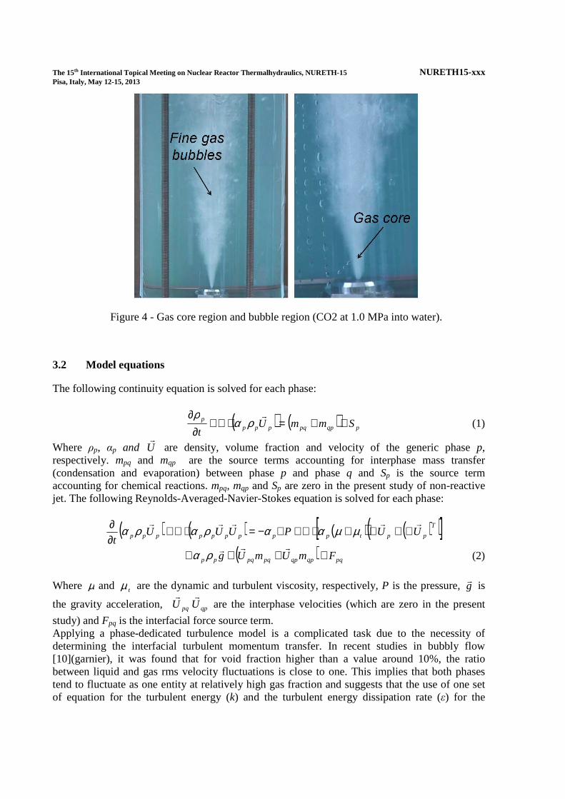
Due to high interfacial slip velocity and important compressibility effects in the gas phase, a two-fluid approach has been adopted for the modelling of the two-phase jet. Closure laws are required for interfacial mass, momentum and energy transfer. Mass transfer will not be considered for the present study, since no evaporation/condensation or chemical reaction occur. For momentum and energy interfacial transfer, an interfacial area must be evaluated. When a highly pressurized gas is injected through a sonic nozzle into a liquid bath at atmospheric pressure, choked condition and consequent gas speed of sound are reached at the nozzle throat. If pressure at choked condition is still higher than downstream pressure, underexpansion occurs downstream the nozzle, leading to local supersonic gas speed in the liquid. As a consequence, slip velocity between gas and liquid phases at the nozzle outlet is very high. This is the case of a CO2 leakage inside the CO2-sodium heat exchanger of an SFR. Farther downstream the nozzle, gas velocity decreases due to interfacial momentum exchange. According to flow regime map in pipes [7](zhang), droplet flow must be assumed for high slip velocity, due to liquid entrainment in the gas phase caused by the instability of the gas-liquid interface, whereas bubbly flow can be assumed for low slip velocity. Using the experimental device described in figure 2, high pressure CO2 (up to 0.1 MPa) has been injected into static water in order to confirm droplet and bubbly flow regime in such a two-phase flow: figure 4 shows a first region near the nozzle representing the gas expansion core, where continuous gas phase is observed. Liquid entrainment can occur in this region. Droplet visual detection could not be possible with the experimental facility used by the authors; however, entrainment phenomena in underexpanded jets were confirmed and reported in literature [8][9](epstein_droplet_size; someya). In a second region, farther downstream the nozzle, gas atomization can be observed, with fine gas bubbles rising in continuous liquid.
The 15th International Topical Meeting on Nuclear Reactor Thermalhydraulics, NURETH-15 NURETH15-xxx Pisa, Italy, May 12-15, 2013
Figure 4 - Gas core region and bubble region (CO2 at 1.0 MPa into water).
3.2 Model equations
The following continuity equation is solved for each phase:
( ) ( ) pqppqpppp SmmU
t++=⋅∇+
∂∂ �
ραρ
(1)
Where ρp, αp and U�
are density, volume fraction and velocity of the generic phase p, respectively. mpq and mqp are the source terms accounting for interphase mass transfer (condensation and evaporation) between phase p and phase q and Sp is the source term accounting for chemical reactions. mpq, mqp and Sp are zero in the present study of non-reactive jet. The following Reynolds-Averaged-Navier-Stokes equation is solved for each phase:
( ) ( ) ( ) ( )( )[ ]T
pptppppppppp UUPUUUt
�����∇+∇+⋅∇+∇−=⋅∇+
∂∂ µµααραρα
( ) pqqpqppqpqpp FmUmUg ++++���ρα (2)
Where µ and tµ are the dynamic and turbulent viscosity, respectively, P is the pressure, g
� is
the gravity acceleration, pqU�
qpU�
are the interphase velocities (which are zero in the present
study) and Fpq is the interfacial force source term. Applying a phase-dedicated turbulence model is a complicated task due to the necessity of determining the interfacial turbulent momentum transfer. In recent studies in bubbly flow [10](garnier), it was found that for void fraction higher than a value around 10%, the ratio between liquid and gas rms velocity fluctuations is close to one. This implies that both phases tend to fluctuate as one entity at relatively high gas fraction and suggests that the use of one set of equation for the turbulent energy (k) and the turbulent energy dissipation rate (ε) for the

The 15th International Topical Meeting on Nuclear Reactor Thermalhydraulics, NURETH-15 NURETH15-xxx Pisa, Italy, May 12-15, 2013 mixture of the continuous and the dispersed phases is appropriated: so, a standard k-ε mixture turbulence model has been adopted in this study for the closure of Reynolds stress tensor. The equations solved by the model are the following:
( ) ( ) ερµσµρρ mijijt
k
tmmm SSkUkk
t−+
∇⋅∇=⋅∇+
∂∂
2�
(3)
( ) ( ) ( )ερµεεσµερερ εε
εmijijt
tmmm CSSC
kU
t ,2,1 2 −⋅+
∇⋅∇=⋅∇+
∂∂ �
(4)
Where the mixture density and mixture velocity are, respectively:
∑=p
ppm ραρ (5)
∑
∑=
ppp
pppp
m
U
Uρα
ρα�
� (6)
In equations [eq:k] and [eq:eps], Sij is the mean rate of strain tensor:
∂∂
+∂∂
=i
j
j
iij x
U
x
US
2
1 (7)
Turbulent viscosity is calculated through equation [eq:turbvisc]:
ερµ µ
2kCmt = (8)
The constants C1,ε, C2,ε, C�, σk and σε have the same value as in the standard k-ε model [11](keps). The following energy equation is solved for each phase:
( ) ( ) ( )[ ] ppqppeffppppppppp HQTt
PhUh
t++∇⋅∇+
∂∂−=⋅∇+
∂∂
,λααραρα�
(9)
Where hp and λeff are the enthalpy and the effective thermal conductivity (t
tpppeff
cp
Pr,
µλλ += ,
with turbulent Prandtl number, Prt, equal to 0.85) of phase p, Qpq is the interfacial heat transfer flux and Hp is the source term taking into account enthalpy released by chemical reaction (which is zero in the present study).
3.3 Interfacial friction calculation
Following considerations in paragraph 3.1, droplet and bubbly flows coexist in the two-phase flow considered. The approach used in the SIMMER-III [12][Morita_SIMMER] computational code has been adopted in the present work: droplet flow is assumed for volume fractions higher than a defined value αd, bubbly flow is assumed for volume fractions lower than a defined value αb and a transition flow is defined by combining the two regions. For the simulation of stratified

The 15th International Topical Meeting on Nuclear Reactor Thermalhydraulics, NURETH-15 NURETH15-xxx Pisa, Italy, May 12-15, 2013 vapor-liquid flow and free-surface flows, the limits αd=0.70 and αb =0.30 have demonstrated good results [13][14][Ahmad_Neptune, Mechitoua_Neptune]. Visual observations described in paragraph 3.1 showed that, in the two-phase jet flow considered, gas atomization occurs for volume fractions certainly higher than 30%. Moreover, well defined continuous gas phase can be observed only in the very high volume fraction region near the gas injection nozzle. Thus, a translation of αd and αb towards higher values is suggested. Good results have been obtained in [15][Uchibori] for the numerical simulation of supersonic gas-into-liquid jets, using the regime flow limits αd =0.95 and αb =0.50. For the present study, the limit αd has been fixed to 0.8, whereas αb has been fixed to 0.50. Two separated drag force equations have been written depending on which flow regime characterizes the computational cell considered:
( ) ( )( )
≤−−
≥−−−
=−=blglglbD
b
dlglggdDd
gDlD
ifUUUUCd
ifUUUUCd
FFααρε
ααρα
����
����
,
,
,,
4
3
1
4
3
(10)
In equations 11, α stands for the gas volume fraction, subscript g and l stand for gas and liquid phase, respectively. In the transition flow regime between αb and αd, the drag law in continuously interpolated between droplet and bubble drag laws, using a logarithmic weighted average. For the determination of droplet flow parameters, useful literature results have been found. In his recent study on liquid entrainment in underexpanded gas-into-liquid jets, M. Epstein [8](epstein_droplet_size) established a correlation for the determination of the droplet SMD dd, which is a function of gas pressure injection and nozzle injection diameter: for gas injection pressure ranging between 0.2 and 1.5 MPa and a nozzle diameter ranging from 1.0 to 2.0 mm, entrained droplet SMD was found to range between 10 and 50 �m. Droplet drag coefficient CD,d has been estimated following the results obtained by Walsh [16](walsh), who investigated particle drag coefficient in high speed gas flow: CD,d is a function of droplet Reynolds number and gas Mach number. Bubble SMD db has been estimated being in the range between 0.2 and 0.5 mm using critical Weber number. Bubble drag coefficient CD,b has been estimated from Schiller and Neumann correlation. However, a correction to this single bubble flow correlation must be applied, since several experimental studies [17][18](rusche; roghair) showed how drag coefficient increases in case of bubble swarms, compared to single bubble flow: following these results, a corrected correlation has been implemented by the authors to take into account drag coefficient enhancement as a function of local gas void fraction. Beside drag force, virtual mass force has been included in the interfacial friction calculation, evaluated through equation 11:
−⋅⋅=−=
Dt
UD
Dt
UDCFF gl
lVMgVMlVM
��
ρα,, (11)
The virtual mass coefficient CVM has been set to 0.5. Considering equation 3, one can write Fpq = FD + FVM.

The 15th International Topical Meeting on Nuclear Reactor Thermalhydraulics, NURETH-15 NURETH15-xxx Pisa, Italy, May 12-15, 2013 3.4 Interfacial heat transfer calculation
As for drag force calculation, also heat transfer coefficient has been estimated differently depending on flow regime. Nusselt number has been calculated following Ranz and Marshall correlation [19](ranz_and_marshall):
≤+==
≥+===
bbbl
b
dddg
d
ifhd
ifhd
Nuαα
λ
ααλ
33.05.0
33.05.0
PrRe6.02
PrRe6.02
(12)
Where Red, Reb, Prd, Prb are Reynolds and Prandtl number of droplet and bubble, respectively, λg and λl are the thermal conductivity of gas and liquid, respectively, and h is the heat transfer coefficient. The interfacial heat transfer flux per unit volume is calculated with equation 13:
glgl ThaQQ ∆⋅⋅=−= lg (13)
The product ha ⋅ in equation 13 has been evaluated assuming droplet flow for α≥αd, bubbly flow for α≤αb, and using a weighted logarithmic average for the transition flow.
3.5 Computational geometry and numerical details
The numerical domain corresponds to the experimental geometry described in fig 2. The water height is fixed to 200 or 300 mm, depending on the parameters investigated, as described in paragraph 2. Computational domain is filled with 76,612 cells and 70,201 cells for the 300 mm and 200 mm, respectively. The nozzle diameter is 1.0 mm and its length is 2 mm: this is the sonic throat length of the nozzle utilized during the experiments performed by the authors.
Mass flow flux has been fixed at the nozzle inlet, which has been calculated using choked flow equations, in order to obtain sonic gas velocity at the nozzle exit. Since experimental and numerical calculations have been performed at sub-critical CO2 pressure values, ideal gas law was used for both CO2 and N2.
The two-fluid model of the software Ansys Fluent 14.0 has been utilized for the solution of the equations. The interfacial momentum and heat transfer models have been implemented into Ansys Fluent through user defined functions. The phase-coupled-SIMPLE algorithm has been adopted for velocity-pressure coupling. Second-order-upwind spatial discretization scheme has been adopted for all equations except for energy equation, for which first-order-upwind has been used due to numerical stability reasons. Implicit temporal scheme has been used, with time step ranging from 1*10-7 to 1*10-6 seconds.

The 15th International Topical Meeting on Nuclear Reactor Thermalhydraulics, NURETH-15 NURETH15-xxx Pisa, Italy, May 12-15, 2013 4. RESULTS
4.1 Upward CO2-into-water jet: numerical and experimental results comparison
The results described in this paragraph have been obtained using CO2 injected into water, both for experimental and numerical investigation. Gas injection temperature and stagnation pressure were fixed to 293K and 0.75 MPa, respectively: the resulting mass flow flux at the nozzle throat is 2121 kg/(m2s). Atmospheric pressure was set as outlet condition at the domain free surface and water temperature inside the pool was set at 293K. Figure 5 shows gas volume fraction profile at different injection transient times. It can be seen that, at the beginning of gas injection, a gas recirculation zone formed in the highest part of the jet is well visible both in the experimental and numerical results (figure 5a and 5b). Figure 6a shows the explanation of the presence of this gas cap: while pushing the water upward, the highest zone of the gas undergoes an inversion in flow direction, leading to tangential and countercurrent velocity directions. Figure 5c shows a more developed transient time, with the typical expansion angle of the jet. It is interesting to check the behaviour of liquid: as shown in figure 6b, the gas recirculation causes a liquid recirculation, which contributes to the liquid entrainment in the gas core closed to the nozzle. Gas sonic velocity at the thermodynamic conditions considered is 249.7 m/s. The gas underexpansion at the nozzle exit leads to supersonic gas velocity: this phenomenon is reproduced by the numerical model, as shown in figure 6a.
Figure 5 - Gas fraction during injection transient of CO2 at 0.75 MPa into water. Numerical results are shown for 25 ms (a), 30 ms (b) and 130 ms (c).

The 15th International Topical Meeting on Nuclear Reactor Thermalhydraulics, NURETH-15 NURETH15-xxx Pisa, Italy, May 12-15, 2013
Figure 6 - Velocity vectors of CO2 (a) and water (b).
4.2 Upward N2-into-water jet: numerical and experimental volume fraction comparison
The results described in this paragraph have been obtained using N2 injected into water, both for experimental and numerical investigation. Gas injection temperature and stagnation pressure were fixed to 293K and 0.70 MPa, respectively: the resulting mass flow flux at the nozzle throat is 1308 kg/(m2s). Optical probe measurements were performed inside N2-into-water upward jets. Some important considerations have to be discussed before detailing the experimental results obtained. Optical probe phase discrimination capability becomes more critical for lower contact time between the optic tip and the dispersed phase: when flow velocity increases and dispersed phase (droplet or bubble) dimension decreases, the success in discriminating the phase depends on the frequency with which the optical signal is captured by the acquisition board. Considering that the two-phase flow here investigated features very high velocities and small dispersed phase dimension, we are interested in checking the maximum phase-discrimination performances of our optical probe measurement system. In order to that, we consider the volume fraction measurements performed on the centreline, 30 mm downstream the nozzle, which is the most critical position investigated: the binary signal obtained by the optical probe apparatus shows a dominant gas phase periodically interrupted by small liquid peaks; the length of these liquid peaks can be measured, and it is found that the shortest ones have a length of 4 �s. According to the numerical results, liquid velocity at 30 mm downstream the nozzle is about 15m/s, which leads to a corresponding particle diameter of 60 �m: this must be considered as the maximum dispersed phase dimension that our apparatus is able to identify. As one can read in paragraph 3, the order of magnitude of this value is the same as the one estimated for the dispersed liquid droplet flow regime estimated for the two-phase jet investigated: nevertheless, we have to take into account the fact the droplet with diameters lower that 60 �m (which are expected to exist as detailed in paragraph 3) cannot be identified by the experimental apparatus. Another phenomenon must be considered regarding optical probe and droplet interactions: since the optical tip diameter and the smallest droplets dimension have the same order of magnitude,

The 15th International Topical Meeting on Nuclear Reactor Thermalhydraulics, NURETH-15 NURETH15-xxx Pisa, Italy, May 12-15, 2013 some of the latter could escape the tip instead of being pierced by it and, therefore, not be identified by the experimental apparatus.
Both numerical and experimental results have been measured for conditions considered as steady state: in reality, strictly steady state conditions are never achieved, since both experimental and numerical results show that the jet is always unstable in the radial direction, featuring a sort of small turning movement around the central axis. However, one can consider the steady state conditions achieved when the time-averaged volume fraction in different sequent time intervals does not change. Figure 7 shows experimental and numerical results in term of void fraction along the jet centerline. The experimental results shown are the averaged values obtained on five different experimental tests: the maximum void fraction standard deviation for the five tests is 2.3%; the reproducibility of the experimental measures is well verified. Numerical results are coherent with the experimental ones: the maximum difference between experimental and numerical void fraction is found to be 8 %, at 90 mm from the nozzle. It is found that the highest experimental value of void fraction is measured at an axial distance of 40 mm, which could be caused by the fact that the optical probe fails to capture the smallest droplet in region very closed to nozzle, were flow velocity are higher. Radial void fraction distribution is also an important information to be checked, since it describes the jet expansion angle and width. For different axial positions (30, 50 and 100 mm), experimental measures were performed varying the radial position of the optical probe from +20 to -20 mm, with sequent steps of 2 mm. Results are reported in figure 8. The numerical model gives very satisfying results: the jet width, calculated as the distance from the centreline to the point where void fraction approaches zero, is very well reproduced by the numerical model. Also the void fraction radial profile across the jet width is well reproduced by the numerical model. The radial profile at the axial distance of 100 mm is not as symmetric (both for experimental and numerical results) as for 30 and 50 mm: this could be due to the jet instability, which causes a movement around the centreline. It has to be considered that experimental radial measurement have been performed only twice for the 100 mm axial distance. The experimental results depict the presence of a local increase of void fraction located at the radial edges of the jet: this can be seen at an axial distance of 30 and 50 mm. The physical explanation to this type of profile is not known by the authors.
50,0%
55,0%
60,0%
65,0%
70,0%
75,0%
80,0%
85,0%
90,0%
95,0%
100,0%
30 40 50 60 70 80 90 100
centerline axial distance [mm]
α
experimental
numerical
Figure 7 - Experimental and numerical void fraction axial profile along the centerline.

The 15th International Topical Meeting on Nuclear Reactor Thermalhydraulics, NURETH-15 NURETH15-xxx Pisa, Italy, May 12-15, 2013
Figure 8 - Experimental and numerical void fraction radial profile for an axial distance of 30, 50 and 100 mm.
0,0%
10,0%
20,0%
30,0%
40,0%
50,0%
60,0%
70,0%
80,0%
90,0%
100,0%
-20 -18 -16 -14 -12 -10 -8 -6 -4 -2 0 2 4 6 8 10 12 14 16 18 20
r [mm]
α
experimental
numerical
0,0%
10,0%
20,0%
30,0%
40,0%
50,0%
60,0%
70,0%
80,0%
90,0%
100,0%
-20 -18 -16 -14 -12 -10 -8 -6 -4 -2 0 2 4 6 8 10 12 14 16 18 20
r [mm]
α
experimental
numerical
0,0%
10,0%
20,0%
30,0%
40,0%
50,0%
60,0%
70,0%
80,0%
90,0%
100,0%
-20 -18 -16 -14 -12 -10 -8 -6 -4 -2 0 2 4 6 8 10 12 14 16 18 20
r [mm]
αexperimental
numerical
z=100
z=50
z=30

The 15th International Topical Meeting on Nuclear Reactor Thermalhydraulics, NURETH-15 NURETH15-xxx Pisa, Italy, May 12-15, 2013
5. CONCLUSION
A two-fluid approach has been developed with the aim of modeling a CO2-into-sodium jet. An experimental facility has been built in order to perform void fraction measurements inside the two-phase jet, utilizing optical probe. Numerical results show good agreement with the experimental ones, in term of axial and radial void fraction profiles for steady-state conditions, and jet shape during initial injection transient. Numerical gas velocity profile shows an increasing from choked to supersonic conditions at the outlet of the sonic nozzle, as it is expected due to underexpansion.
The numerical approach here described will be used as the base for the introduction of the Na-CO2 chemical reaction. The authors have developed a reaction model which describes the reaction occurring between a sodium droplet and the surrounding CO2: results have been obtained in term of sodium droplet depletion rate, as a function of the most important parameters, such as droplet Reynolds number, droplet temperature and CO2 concentration at bulk conditions. These results will be utilized for implementing a reaction rate mechanism inside the two-fluid CFD model.
Acknowledgment
Authors would like to express their thanks to the technical contribution given by Gilles Gobillot, Eric Hervieu and Marion Perrais of CEA Cadarache.
6. REFERENCES
[1] A. Moisseytsev and J. J. Sienicki, “Investigation of alternative layouts for the supercritical carbon dioxide brayton cycle for a sodium-cooled fast reactor,” Nuclear Engineering and Design, vol. Volume 239, pp. 1362–1371, 2009.
[2] J. J. Sienicki et al., “Sodium-cooled fast reactors under the generation iv international forum component design and balance of plant project,” in International Congress on Advances in Nuclear Power Plants 2010 (ICAPP 2010) San Diego, California, USA, 13-17 June 2010, 2010.
[3] Y. Muto, T. Ishizuka, and M. Aritomi, “Conceptual design of a commercial supercritical co2 gas turbine for the fast reactor power plant,” in International Congress on Advances in Nuclear Power Plants 2010 (ICAPP 2010) San Diego, California, USA, 13-17 June 2010.
[4] S. Kishore et al., “An experimental study on impingement wastage of mod 9cr 1mo steel due to sodium water reaction,” Nuclear Engineering and Design, vol. Volume 243, pp. 49–55, 2012.
[5] L. Gicquel, Etude des mécanismes et cinétiques des interactions sodium CO2. Contribution à la évaluation de un système de conversion de la énergie au CO2 supercritique pour les réacteurs rapides à caloporteur sodium. PhD thesis, 2010.
[6] L. Gicquel et al., “Supercritical co2 brayton cycle coupled with a sodium fast reactor: Na/co2 interaction experiments and modeling,” in International Congress on Advances in Nuclear Power Plants 2010 (ICAPP 2010) San Diego, California, USA, 13-17 June 2010.

The 15th International Topical Meeting on Nuclear Reactor Thermalhydraulics, NURETH-15 NURETH15-xxx Pisa, Italy, May 12-15, 2013 [7] J. Zhang et al., “Flowregimeidentification in gas-liquidflow and three-phase fluidizedbeds,” Chemical Engineering Science, vol. 52, pp. 3979–3992, 1997.
[8] H. K. F. M. Epstein and N. Yoshioka, “Establishment of analytical model for peak temperature within a sodium-water reaction jet ii mean droplet size in a submerged gas jet,” Journal of Nuclear Science and Technology, vol. 42, pp. 961 – 969, 2005.
[9] Y. L. S. Someya and K. Okamoto, “An entrained droplet by an underexpanded gas jet into water,” 15th Int Symp on Applications of Laser Techniques to Fluid Mechanics, Lisbon, Portugal, 05-08 July, 2010, 2010.
[10] J. M. C. Garnier, M. Lance, “Measurement of local flow characteristics in buoyancy-driven bubbly flow at high void fraction,” Experimental Thermal and Fluid Science, vol. 26, pp. 811–815, 2002.
[11] B. E. Launder and D. B. Spalding, Lectures in Mathematical Models of Turbulence. 1972.
[12] K. Morita et al., “Applications of the simmer-iii fast reactor safety analysis code to thermal interactions of melts with sodium and water,” in 7th International Conference on Nuclear Engineering, Tokyo, Japan, April 19-23, 1999, ICONE-7250, 1999.
[13] M. Ahmad et al., “Cfd simulation of a stratified flow at the inlet of a compact plate heat exchanger,” Computational Methods in Multiphase Flow IV, vol. 56, 2007.
[14] N. Mechitoua et al., “Assessment of neptune cfd code for some free surface flows interesting fluvial hydraulic,” in 7th International Conference on Multiphase Flow, ICMF 2010, Tampa, FL USA, 2010.
[15] A. Uchibori, A. Watanabe, and H. Ohshima, “Numerical analysis of supersonic gas jets into liquid pools with or without chemical reaction using the seraphim program,” Nuclear Engineering and Design, vol. 249, pp. 35–40, 2011.
[16] M. J. Walsh, “Influence of particle drag coefficient on particle motion in high-speed flow with typical laser velocimeter applications,” NASA Technical Note D-8120, 1976.
[17] H. Rusche and R. Issa, “The effect of voidage on the drag force on particles, droplets and bubbles in dispersed two-phase flow,” In Japanese European Two-Phase Flow Meeting, Tshkuba, Japan, 2000.
[18] M. S. I. Roghair and H. Kuipers, “Drag force on bubbles in bubble swarms,” Seventh International Conference on CFD in the Minerals and Process Industries CSIRO, Melbourne, Australia 9-11 December 2009, 2009.
[19] W. E. Ranz and W. R. Marshall, “Evaporation from drops, i and ii,” Chem. Eng. Prog., vol. 48, pp. 141–146, 1952.