Experimental investigations on post-tensioned structural ... · PDF fileExperimental...
8
Experimental investigations on post-tensioned structural glass beams Michael Engelmann 1) and *Bernhard Weller 2) 1), 2) Technische Universität Dresden, 01062 Dresden, Germany 2) [email protected] ABSTRACT At Technische Universität Dresden, structural glass researchers are developing an innovative concept for mechanical pre-stressing glass beams. These beams are post-tensioned by unbonded cables, which are anchored at the beam-ends. Two different cable layouts are chosen to investigate on an optimized global load bearing behavior and depend on the expected external bending loads and the chosen construction especially in terms of the supports and the connection to the glazing. To increase the loadbearing capacity as well as the post fracture behavior reinforced glass beams in multiple applications may be post-tensioned. An embedded steel cable as it is known from the principles of reinforced concrete design is tensioned creating an internal constraint. This will result in a compressive stress constraint state in the glass. Additionally, the deformation of such a beam may be affected as needed before an external bending load appears. Nevertheless, glass beams are subject to imperfections. Due to this initially unknown deviation from the theoretical perfect state, the applied axial force from post- tensioning the beams will induce additional torsion as well as further bending moments. This may result in an unfavorable deformation of the glass beam during the post- tensioning process and increase the risk to suffer from early failure such as lateral torsional buckling. The results of the experimental investigation in terms of load-cable force and load-deformation relations caused by four-point bending are summarized and analyzed. Furthermore, the deformation behavior is compared between the different cable layouts leading to a conclusion what construction is most suitable to be post-tensioned from the perspective of this very load case. The project was funded through the German Federal Ministry of Economics and Energy (BMWi). 1) Professor 2) Senior Researcher
Transcript of Experimental investigations on post-tensioned structural ... · PDF fileExperimental...
Experimental investigations on post-tensioned structural glass beams
Michael Engelmann1) and *Bernhard Weller2)
1), 2) Technische Universität Dresden, 01062 Dresden, Germany 2) [email protected]
ABSTRACT
At Technische Universität Dresden, structural glass researchers are developing an innovative concept for mechanical pre-stressing glass beams. These beams are post-tensioned by unbonded cables, which are anchored at the beam-ends. Two different cable layouts are chosen to investigate on an optimized global load bearing behavior and depend on the expected external bending loads and the chosen construction especially in terms of the supports and the connection to the glazing.
To increase the loadbearing capacity as well as the post fracture behavior
reinforced glass beams in multiple applications may be post-tensioned. An embedded steel cable as it is known from the principles of reinforced concrete design is tensioned creating an internal constraint. This will result in a compressive stress constraint state in the glass. Additionally, the deformation of such a beam may be affected as needed before an external bending load appears.
Nevertheless, glass beams are subject to imperfections. Due to this initially
unknown deviation from the theoretical perfect state, the applied axial force from post- tensioning the beams will induce additional torsion as well as further bending moments. This may result in an unfavorable deformation of the glass beam during the post- tensioning process and increase the risk to suffer from early failure such as lateral torsional buckling.
The results of the experimental investigation in terms of load-cable force and
load-deformation relations caused by four-point bending are summarized and analyzed. Furthermore, the deformation behavior is compared between the different cable layouts leading to a conclusion what construction is most suitable to be post-tensioned from the perspective of this very load case. The project was funded through the German Federal Ministry of Economics and Energy (BMWi).
1) Professor 2) Senior Researcher

1. INTRODUCTION
Glass is the building material of the 21st century: it makes structures of
maximized transparency possible, which results in an efficient utilization of natural daylight – occupants enjoy an unobstructed outside view. Therein, glass beams play and outstanding role in terms of facade mullions or roof girders. Those structures make use of the natural material strength of glass while maintaining the invisible concept. However, glass is a brittle material; unintended fracture cannot be fully prevented. To overcome this concern, several research projects came up with the approach to add a ductile reinforcement in the cross section – an approach adopted from reinforced concrete design. Martens (2015) gives a broad overview of reinforcement concepts. Pre-compressed options with unbonded tendons are available in Bos (2004) and Engelmann (2016) while Louter (2015) proposes a linear bond.
Following this analogy, the reinforcement may be post-tensioned or pre-tensioned
in order to pre-compress the glass. This results in an increase in initial fracture strength and allows for an intentional uplift of the beam. Additionally, the reinforcement provides a redundant load-path in case of glass failure. This approach is utilizable as a result of all available investigations. Nevertheless, there is no consistent and complete design available. Especially the long-term effects may cause a loss in pretension and a robust response in case of unintended failure is missing.
As a result, a comprehensive research at the Institute of Building Construction at
Technische Universität Dresden was initiated including an extensive experimental campaign during short-term and long-term bending loads as well as during an intended fracture situation. This will add to available preliminary results in terms of the design and detailing of post-tensioned structural glass beams. This paper will give an overview of the results.
Fig. 1 Crack pattern of a 9.0 m post-tensioned glass beam. Engelmann (2016)
2. GLASS AND CONCRETE
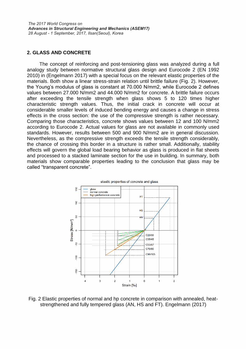
The concept of reinforcing and post-tensioning glass was analyzed during a full analogy study between normative structural glass design and Eurocode 2 (EN 1992 2010) in (Engelmann 2017) with a special focus on the relevant elastic properties of the materials. Both show a linear stress-strain relation until brittle failure (Fig. 2). However, the Young’s modulus of glass is constant at 70.000 N/mm2, while Eurocode 2 defines values between 27.000 N/mm2 and 44.000 N/mm2 for concrete. A brittle failure occurs after exceeding the tensile strength when glass shows 5 to 120 times higher characteristic strength values. Thus, the initial crack in concrete will occur at considerable smaller levels of induced bending energy and causes a change in stress effects in the cross section: the use of the compressive strength is rather necessary. Comparing those characteristics, concrete shows values between 12 and 100 N/mm2 according to Eurocode 2. Actual values for glass are not available in commonly used standards. However, results between 500 and 900 N/mm2 are in general discussion. Nevertheless, as the compressive strength exceeds the tensile strength considerably, the chance of crossing this border in a structure is rather small. Additionally, stability effects will govern the global load bearing behavior as glass is produced in flat sheets and processed to a stacked laminate section for the use in building. In summary, both materials show comparable properties leading to the conclusion that glass may be called “transparent concrete”.
Fig. 2 Elastic properties of normal and hp concrete in comparison with annealed, heat- strengthened and fully tempered glass (AN, HS and FT). Engelmann (2017)

3. METHODS The load-bearing behavior of glass beams was described by four-point bending
tests until initial failure and the subsequent post-failure state during a propagation in bending load (short-term bending tests). Additionally, the brittle failure of glass beams has to be considered as the consequences of failure will lead to considerable consequences (fail-safe). This was addressed by bending tests during a constant bending load at serviceability level, an intentional shattering of single glass layers and measurement of the remaining service life (post-breakage bending tests). Both test results were governed by the cracking pattern of the chosen base material. Finally, it is known from reinforced concrete design that the tension force will decrease with time due to creeping of the concrete and relaxation of the reinforcement material. As several plastic materials were loaded in a glass beam structure, a reduction in initial tendon force was expected. To quantify the loss in pre-stress, long-term bending test for a period of 1.000 h were performed.
In order to compare results at a common level, all specimens were essentially
the same (Fig. 3). The span was 2,0 m while the height of the beams was 150 mm. The cross section consisted of two packages of laminated glass made from 6 mm heat- strengthened (HS) glass as a result of preliminary investigations in Weller (2014). Both parts of the beam were separated by means of adhesively bonded stainless steel connectors at the bottom and top edge of the glass. This gave room to hold a stainless steel spiral cable in the gap, which was redirected as needed. The cable was fixed at the ends of the beams post-tensioned up to the designated tendon load.
Fig. 3 Schematic layout of specimen (top) and photo of the test-rig (bottom).

4. RESULTS AND DISCUSSION
The results in this section summarize the experimental campaign. Figures 4 and 5 give the measurements of a specimen with a 8,1 mm cable at an initial cable load of 15 kN as an example.
3.1 Short-term bending tests A total of 15 specimens were tested experimentally in bending where the vertical
deflection of the cross beam wz.T provoked a bending load F (deflection-controlled). The tendon size was 6,1 mm, 8,1 mm and 10,1 mm with initial cable loads of 9,0 kN and 15,0 kN in three specimens each. Additionally, three unreinforced specimens and three beams with untensioned cables of 10,1 mm were used.
The results showed an uplift during the tensioning stage, which is describable by
means of linear beam theory. During the subsequent loading stage the cable force increased as well proofing a mutual load transfer between glass and reinforcement. Fig. 4 (left) shows an increase from 15,0 kN to 20,7 kN in cable load Np while the bending load increased to 34,1 kN. Thus, the change in cable load of 0,167 kN/kN results in a relative change in reinforcement stress of 4,3 N/(mm2 · kN)
Additionally, the post-tensioning process resulted in a compression of the bottom
glass edge, while the top edge was tensioned (Fig. 4, right). At about 3 mm of cross beam deflection, the glass was decompressed.
Finally, the glass failed in three different modes. The first type was a brittle failure
and a loss in structural integrity. Secondly, after the initial brittle cracking, a consecutive loading of the broken cross section was possible, but at a bending load smaller than the initial failure load. Finally, after the first brittle failure, a progressive loading was possible. The example in Fig. 4 illustrates the second mode as the cross beam is free to deflect for an additional 4 mm after initial fracture. It should be noted that the maximal cable load of 21.1 kN was recorded during this stage.
Fig. 4 Bending load F and cable load Np (left). Strain of the glass edges εx in terms of mean values from two gauges (right).

All specimens showed an increase in initial fracture load. An accompanying
measurement of the strain in the glass showed that the actual failure stress remained at the expected level. This showed the beneficial effect of the post-tensioning procedure on the load-bearing behavior of the beams. However, it should be noted that the strength of glass is a value, which is spreads larger than in other traditional materials. Usually, a variation coefficient of 0,1 to 0,2 is possible in strength tests. This was reflected in the results by a large range in fracture loads of the reference specimens.
3.2 Residual load bearing bending tests Unquantifiable actions such as vandalism, hard-body impacts or stress
concentration caused by nickel-sulfide inclusions in tempered glass may cause spontaneous glass failure irrespective of the load conditions. Therefore, a test scenario with 24 specimen with cable diameters of 5,0 mm, 8,1 mm and 10,1 mm at initial cable loads of 9,0 kN and 15,0 kN, including eight reference specimen, was performed. A constant bending load of 10 kN (1/3 of the mean initial failure load) was chosen. This reflected a serviceability level.
Using a chisel and a hammer, each layer in the laminated glass cross section was
shattered followed by a 24 h waiting period. The time until ultimate failure – remaining service life – was recorded. The example in Fig. 5 (left) illustrates the cable load during an exemplary test. A cable load of 16.8 kN resulted from tensioning the cable and loading the beam in bending. The shattering of each layer resulted in an increase of cable force to 16,9 kN (0 h), 16,4 kN (24 h), 17.2 kN (48 h) and 21,2 kN (72 h) However, other types of failures were recorded as well but without further correlation to a possible cause. Therefore, further investigations are necessary.
All specimen showed a robust response during the first 48 h of the tests. During
this time, the load was redistributed from the broken layers to the intact glass and the tendons. Therefore, it was concluded that a provision of a redundant load path is feasible. Additionally, this loading stage is decisive for the design of the tendons.
As an exception to this rule, two specimen of the maximal initial cable load
showed an uncommonly coarse breakage pattern and an extensive lateral deflection after shattering the primary glass layer. In contrast to reference specimen, this effect was recorded for the first time. As a conclusion, it was recommended to include the lateral stability of the glass during the design of post-tensioned glass beams.
3.3 Long-term bending tests A service-load of 10 kN was applied for 1.000 h in the same manner. During this
period, the deflection and the cable load was recorded every 10 minutes. In analogy to pre-stressed concrete structures, it was expected to lose cable force, which may reject the concept of post-tensioned glass beams.
As an illustration, Fig. 5 (right) gives the results of a specimen with an 8,1 mm
cable at an initial cable force of 15,0 kN. The test duration started after loading the

beam in bending. During the course of 1.000 h the cable force dropped by 3,1 kN to 12,9 kN. The main part of this loss was recorded during the initial part of the test of 200 h. However, the further progression decreased, but did not reach a final threshold during the test.
Fig. 5 Cable load Np during residual load bearing bending test (left). Change of cable load during long-term bending tests at room-temperature range T (right).
As a considerable contribution, the same types of results for all specimens may be used to derive a model, to calculate the loss of cable force, which depends on the loaded materials in the structure.
5. CONCLUSIONS AND SUMMARY The given summary is based on an analogy study between the elastic properties of glass and concrete. This set the basis for a broad experimental campaign focusing on three relevant properties. At first, a study during short term bending loads confirmed an increase in initial fracture load. Additionally, the load-bearing behavior was predictable my means of linear beam theory. The utilized construction and the structural detailing showed no significant impact. Thus, the idea of post-tensioning a glass beam mechanically and a structural idealization is realizable. Afterwards, the post-breakage tests showed an important safety feature of glass beams. The cables were able to support the shattered glass and gave additionally redundancy. Finally, it was noted that a post-tensioning might work unfavorable as well as it may induce an eccentric bending moment in a broken state, which causes failure. Additionally, long-term effects reduced the cable force and needs further investigation to develop a model in analogy to Eurocode 2, which allows a prediction of the losses.
In summary, the particular set of results indicated a novel structural option to design safe and durable as well as transparent and economic glass beams for a future design of outstanding glass facades and bridges.

ACKNOWLEDGMENTS
The research project was sponsored by the German Federal Ministry of Economics and Technology (BMWi) and was executed corporately with Thiele Glas Werk GmbH (Wermsdorf, GERMANY) and KL-megla GmbH (Eitorf, GERMANY). Additionally, PFEIFER Seil- und Hebetechnik GmbH (Memmingen, GERMANY) gave valuable support.
REFERENCES
Engelmann, M. (2017), “Spannglasträger – Glasträger mit vorgespannter Bewehrung
(Spannglass Beams – Glass Beams with Post-tensioned Reinforcement)“, Dissertation (in German), Technische Universität Dresden.
Martens, K., Caspeele, R., Belis, J. (2015), “Development of Reinforced and Posttensioned Glass Beams: Review of Experimental Research.” Journal of Structural Engineering, ASCE, 142(5).
Bos, F. P., Veer, F. A., Hobbelman, G. J., et.al. (2004), “Stainless steel reinforced and post-tensioned glass beams.” Proceedings of the 12th International Conference of Experimental Mechanics (ICEM12), Bari, Italy.
Louter, C., Cupac, J., Lebet, J.-P. (2014), “Exploratory experimental investigations on post-tensioned structural glass beams.” Journal of Facade Design and Engineering 2(1-2), 3-18.
Engelmann, M., Weller, B. (2016), “Post-Tensioned Glass Beams for a 9 m Spannglass Bridge.” In: Structural Engineering International 26(2), 103–113.
Weller, B.; Engelmann, M. (2014), “Spannglasträger – Glasträger mit vorgespannter Bewehrung.“ Stahlbau 83(1), 193–203.
EN 1992 (2010), Design of concrete structures.