EXPERIMENTAL INVESTIGATIONS OF PIPELINE FILLING AND ...
12
JET 11 JET Volume 11 (2018) p.p. 11-22 Issue 2, September 2018 Type of arcle 1.01 www.fe.um.si/en/jet.html EXPERIMENTAL INVESTIGATIONS OF PIPELINE FILLING AND EMPTYING IN A SMALL-SCALE APPARATUS EKSPERIMENTALNE RAZISKAVE POLNJENJA IN PRAZNJENJA CEVOVODA MALIH IZMER Uroš Karadžić R , Anton Bergant 1 Keywords: pipeline, filling, emptying, instrumentaon, results of measurements Abstract This paper serves as a reference for further invesgaons of pipeline filling and emptying in a rela- vely small-scale pipeline apparatus. The apparatus consists of an upstream end high-pressurized tank, horizontal steel pipeline, four valve units posioned along the pipeline including the end- points, and a downstream end tank. The filling of an inially empty pipeline is performed by a sudden opening of the valve posioned at the high-pressurized tank filled with water. The pipeline- emptying process is accomplished by high-pressurized air supplied from the air reservoir installed at the high-pressurized tank. The high-pressurized tank is closed, and the downstream end valve is opened. Experimental results indicate that pressure fluctuaons are larger for pipeline filling in comparison to pipeline emptying. It is shown that a piezoelectric transducer with a fixed relavely low discharge me constant is not enrely appropriate for accurate low-frequency pressure mea- surements. R Corresponding author: Uroš Karadžić, PhD, Faculty of Mechanical Engineering, University of Montenegro, Džordža Vašingtona bb, ME-81000 Podgorica, Montenegro, [email protected] 1 Anton Bergant, PhD, Full me: Litostroj Power d.o.o., Litostrojska 50, 1000 Ljubljana, Slovenia, [email protected]; Part me: Faculty of Mechanical Engineering, University of Ljubljana, Aškerčeva 6, 1000 Ljubljana, Slovenia
Transcript of EXPERIMENTAL INVESTIGATIONS OF PIPELINE FILLING AND ...

JET 11
JET Volume 11 (2018) p.p. 11-22Issue 2, September 2018
Type of article 1.01www.fe.um.si/en/jet.html
EXPERIMENTAL INVESTIGATIONSOF PIPELINE FILLING AND EMPTYING
IN A SMALL-SCALE APPARATUS
EKSPERIMENTALNE RAZISKAVE POLNJENJA IN PRAZNJENJA CEVOVODA
MALIH IZMER
Uroš KaradžićR, Anton Bergant1
Keywords: pipeline, filling, emptying, instrumentation, results of measurements
AbstractThis paper serves as a reference for further investigations of pipeline filling and emptying in a rela-tively small-scale pipeline apparatus. The apparatus consists of an upstream end high-pressurized tank, horizontal steel pipeline, four valve units positioned along the pipeline including the end-points, and a downstream end tank. The filling of an initially empty pipeline is performed by a sudden opening of the valve positioned at the high-pressurized tank filled with water. The pipeline-emptying process is accomplished by high-pressurized air supplied from the air reservoir installed at the high-pressurized tank. The high-pressurized tank is closed, and the downstream end valve is opened. Experimental results indicate that pressure fluctuations are larger for pipeline filling in comparison to pipeline emptying. It is shown that a piezoelectric transducer with a fixed relatively low discharge time constant is not entirely appropriate for accurate low-frequency pressure mea-surements.
R Corresponding author: Uroš Karadžić, PhD, Faculty of Mechanical Engineering, University of Montenegro, Džordža Vašingtona bb, ME-81000 Podgorica, Montenegro, [email protected]
1 Anton Bergant, PhD, Full time: Litostroj Power d.o.o., Litostrojska 50, 1000 Ljubljana, Slovenia, [email protected]; Part time: Faculty of Mechanical Engineering, University of Ljubljana, Aškerčeva 6, 1000 Ljubljana, Slovenia

12 JET
Uroš Karadžić, Anton Bergant JET Vol. 11 (2018)Issue 2
2 Uroš Karadžić, Anton Bergant JET Vol. 11 (2018) Issue 2
‐‐‐‐‐‐‐‐‐‐
Povzetek Prispevek daje osnove za nadaljne raziskave polnjenja in praznjenja cevovoda relativno malih izmer. Preizkusno postajo sestavljajo gorvodna visokotlačna posoda, horizontalni jekleni cevovod, štirje bloki z ventili vgrajeni vzdolž cevovoda in robovih ter dolvodna posoda. Polnjenje praznega cevovoda izvedemo s hitrim odpiranjem ventila, ki je vgrajen pri gorvodni visokotlačni posodi napolnjeni z vodo. Praznjenje cevovoda napolnjenega z vodo dosežemo z vpihovanjem komprimiranega zraka na gorvodnem koncu. Visokotlačna posoda je pri tem zaprta, dolvodni ventil pa odprt. Rezultati meritev kažejo, da so tlačne obremenitve večje pri polnjenju cevovoda. Izkazalo se je, da piezometrično tlačno zaznavalo z relativno nizko tokovno konstantno ni najbolj primerno za merjenje nizkofrekvenčnih tlakov.
1 INTRODUCTION
The filling with liquid of an initially empty pipeline and the emptying of an initially liquid‐filled pipeline are of great interest due to the many practical applications. Rapid pipe filling and emptying occur in various hydraulic applications, such as water‐distribution networks, storm‐water and sewage systems, fire‐fighting systems, oil transport pipelines, and pipeline cleaning. During the rapid filling of an empty pipeline, while the water column is driven by a high head, air is expelled by the advancing water column. For emptying of a pipeline initially filled with water, water is expelled out of the system while the air is blown into the pipeline, [1]. Rapid filling and emptying of the pipeline may be considered as a specific case of water hammer with column separation in which both vaporous and gaseous cavities may be present, [2]. The filling and the emptying of the large‐scale pipelines has been experimentally studied, [1], [3], [4], [5].
Developers and users of computational codes (in‐house, commercial) need measurement data with which to compare their theoretical models. Unfortunately, such data are limited and fragmented. There is a strong need for enhanced well‐controlled measurements of the water hammer, column separation, fluid‐structure interaction, and pipeline filling and emptying. To address these needs, a flexible experimental apparatus has been developed and installed at the University of Montenegro, [6]. The small‐scale apparatus consists of an upstream end high‐pressurized tank, horizontal steel pipeline (length 55.37 m, inner diameter 18 mm), four valve units positioned along the pipeline including the endpoints, and a downstream end tank (outflow tank). The first tests of filling and emptying have been performed recently, and the initial results of the measurements are presented and discussed in this paper, an extended and updated version of a conference paper, [7].
2 EXPERIMENTAL APPARATUS
A small‐scale unsteady friction‐dominated pipeline apparatus has been designed and constructed at the Faculty of Mechanical Engineering, University of Montenegro, [6], for investigating rapid water hammer events including column separation and fluid‐structure interaction (pressure changes last for few seconds only), [6]. Recently the apparatus has been modified for performing pipeline filling and emptying events that are characterized both by rapid and gradual pressure changes, [4], [5]. The apparatus is comprised of a horizontal pipeline

JET 13
Experimental investigations of pipeline filling and emptying in a small-scale apparatus Experimental investigations of pipeline filling and emptying in a small‐scale apparatus 3
that connects the upstream end high‐pressurized tank to the outflow tank (steel pipe of total length L = 55.37 m (Ux = ±0.01 m); internal diameter D = 18 mm (Ux = ±0.1 mm); pipe wall
thickness e = 2 mm (Ux = ±0.05 mm); maximum allowable pressure in the pipeline pmax,all = 25 MPa); see Fig. 1. The uncertainty in a measurement Ux is expressed as the root‐sum‐square combination of bias and precision error, [8].
Upstream endhigh-pressurized tank
P C
Outflow tank
Horizontal steel pipeline - internal diameter D = 18 mm
- full-length L = 55.37 m
P
C
Electro-pneumatically-operated ball valve
Hand-operated ball valve
Control needle valve
Pressure transducer
Bend (R = 3D)x = 0.0 mp0/3: 1.76 m6.65 m
p1/3: 18.11 m
29.92 m p2/3: 36.09 m 36.97 m
50.33 m p3/3: 53.34 m x = L = 55.37 m
V0/3D: 1.85 m
V1/3U: 18.02 mV1/3D: 18.20 m
V2/3U: 36.00 mV2/3D: 36.20 m
V3/3P: 53.47 mV3/3H: 53.60 m
Bend (R = 3D) Bend (R = 3D)
0.0 m
V3/3C: 53.91 mV3/3E: 54.00 m
V0/3U: 1.67 m
V0/3SH:1.26 m
1.46 m
V0/3ASV0/3AV
V0/3SV
V0/3A
p3/3-sg: 53.76 m
Figure 1: Layout of small‐scale pipeline apparatus
Four valve units are positioned along the pipeline, including the endpoints. Valve units at the upstream end tank (position 0/3) and at the two equidistant positions along the pipeline (positions 1/3 and 2/3) are comprised of two hand‐operated ball valves (valves Vi/3U and Vi/3D; i = 0, 1, 2) that are connected to the intermediate pressure transducer block. A T‐section with an on/off air inlet valve (V0/3A) and a compressed‐air supply valve (V0/3AS) is installed between the upstream end valve unit (position 0/3) and the high‐pressurized tank to facilitate pipeline emptying tests. At the T‐section, there is also an air vent valve (V0/3AV) and a vertical pipe upstream end service valve (V0/3SV). A horizontal pipe upstream end service valve (V0/3SH) is installed between the T‐section and the high‐pressurized tank in order to isolate the upstream end tank during emptying tests. There are four 90o bends along the pipeline with a radius of curvature R = 3D. The pipeline is anchored against the axial movement at 37 points (as close as possible to the valve units and bends). The anchors are loosened for fluid‐structure interaction tests. The air pressure in the upstream end tank (total volume HPT = 2 m3;

14 JET
Uroš Karadžić, Anton Bergant JET Vol. 11 (2018)Issue 2
4 Uroš Karadžić, Anton Bergant JET Vol. 11 (2018) Issue 2
‐‐‐‐‐‐‐‐‐‐
maximum allowable pressure in the tank pHPTmax,all = 2.2 MPa) can be adjusted up to 800 kPa. The pressure in the tank is kept constant during each experimental run by using a high precision air pressure regulator (precision class: 0.2%) in the compressed air supply line, [6]. The upstream end tank is used for the pipeline filling experiment where the valve V0/3A is closed, thus enabling isolation of the compressed air supply into the horizontal steel pipeline.
2.1 Instrumentation
Four dynamic high‐frequency pressure transducers are positioned within the valve units along the pipeline including the endpoints (see Fig. 1). Pressures p0/3, p1/3, p2/3, and p3/3 are measured by Dytran 2300V4 high frequency piezoelectric absolute pressure transducers (pressure range: from 0 to 6.9 MPa; resonant frequency: 500 kHz; acceleration compensated; discharge time constant: 10 seconds (fixed); Ux = ±0.1 %). All four piezoelectric transducers were flush mounted to the inner pipe wall. These transducers perform accurately for rapid water hammer events including column separation and fluid‐structure interaction, [6]. In these events, the water hammer pressure pulse in the apparatus (Fig. 1) lasts about or less than the wave reflection time 2L/a = 0.08 seconds, which is an event lasting less than 10/100 of a second, during which the sensor will discharge 1% of the voltage. Because of the relatively short discharge time constant of these transducers which cannot be adjusted, a question is posed regarding their applicability for measurements of “rapid” filling and emptying events. Therefore, an Endress+Hauser PMP131 strain‐gauge pressure transducer has been installed at the control valve V3/3C (pressure p3/3‐sg; pressure range: from 0 to 1 MPa; Ux = ±0.5 %). This transducer does not discharge the voltage (analogue output); consequently, it can be used for the measurement of “slow” events (low frequency). Figure 2 shows the layout of the downstream end valve unit with instruments including two pressure transducers (Dytran 2300V4 and Endress+Hauser PMP131).

JET 15
Experimental investigations of pipeline filling and emptying in a small-scale apparatus Experimental investigations of pipeline filling and emptying in a small‐scale apparatus 5
Figure 2: Layout of downstream end valve unit with instruments
The datum level for all pressures measured in the pipeline and at the tank is at the top of the horizontal steel pipe (elevation 0.0 m in Fig. 1). For initial flow velocities larger than 0.3 m/s, an electromagnetic flow meter is used (Ux = ±0.2%). The water temperature is continuously monitored by the thermometer installed in the outflow tank. The water hammer wave speed was determined as a = 1340 m/s (Ux = ±0.1%).
2.2 Test procedure for pipeline filling
The test procedure for the pipeline filling is as follows. The pressure in the upstream end high‐pressurized tank is adjusted to a desired value using a high precision air pressure regulator. The control needle valve (V3/3C) is opened to the appropriate position. The upstream end valve (V0/3U) at the pressurized tank (position 0/3 in Fig. 1) is closed. All other valves of the four valve units are fully opened. The air inlet valve (V0/3A) is closed (isolation of the compressed air supply into the pipeline), and the horizontal pipe upstream end service valve (V0/3SH) and the downstream end emptying valve (V3/3E) are opened. The filling of the initially empty pipeline is initiated by quickly opening valve V0/3U. When a steady state is achieved, the final flow velocity (Vf) is measured using an electromagnetic flowmeter.

16 JET
Uroš Karadžić, Anton Bergant JET Vol. 11 (2018)Issue 2
6 Uroš Karadžić, Anton Bergant JET Vol. 11 (2018) Issue 2
‐‐‐‐‐‐‐‐‐‐
2.3 Test procedure for pipeline emptying
The pipeline is emptied using compressed air supplied from the air reservoir connected to a high precision air pressure regulator. The air pressure for the pipeline emptying is first adjusted to a desired value as well as the opening of the control needle valve. All valves of the four valve units and the horizontal pipe upstream end service valve (V0/3SH) are fully opened. The air inlet valve (V0/3A) (isolation of T‐section) and the downstream end emptying valve (V3/3E) are closed. Next, the high‐pressurized tank is isolated from the system by shutting the horizontal pipe upstream end service valve (V0/3SH); after that, the compressed‐air supply valve (V0/3AS) and the air inlet valve (V0/3A) are opened. The process of emptying is started by quickly opening the downstream end emptying valve (V3/3E).
3 RESULTS OF MEASUREMENTS
This section presents measurement results from pipeline filling and emptying runs in a small‐scale experimental apparatus (see Fig. 1). All experimental runs have been carried out for the “same” initial conditions at least three times to achieve repeatability of experiments. The measurements include pipeline filling and the emptying runs with different initial values of the pressure (pHPT = 300 and 400 kPa) in the high‐pressurized upstream tank (filling procedure) and air supply line (emptying procedure).
3.1 Pipeline filling
Figure 3 shows a comparison of heads at the two end valve sections and along the pipeline for the case of pipeline filling with the “same” initial conditions (repeatability study). The pressure in the upstream end tank is pHPT = 400 kPa (head HHPT = 39.2 m), the control needle valve is fully open, and the final flow velocity in the pipe after the filling process is completed is Vf = 2.21 m/s. From Fig. 3, it can be seen that bulk patterns of the pressure history during filling events are similar for both tests. As explained in Section 2.1, Dytran 2300V4 dynamic pressure transducers accurately measure high‐frequency pressure changes. Therefore, when a new steady state is attained after some time, these transducers do not show the final value of the pressure because the signal discharges to its initial state (63% discharge drop in 10 seconds). Figure 4 shows a comparison of heads at the downstream end of the pipeline (position 3/3 in Fig. 1) measured both by the Dytran 2300V4 piezoelectric pressure transducer and by the E+H PMP131 strain‐gauge pressure transducer for Test 1. It can be seen that the E+H transducer, after the filling process is completed, shows the steady state (actual) value of the pressure, which is not the case with the Dytran transducer (step‐like pressure pulse).

JET 17
Experimental investigations of pipeline filling and emptying in a small-scale apparatus Experimental investigations of pipeline filling and emptying in a small‐scale apparatus 7
Figure 3: Comparison of heads at the end valves (H3/3 and H0/3) and along the pipeline
(H2/3 and H1/3) for the same initial conditions: pipeline filling
Figure 4: Comparison of heads at the position 3/3 measured by Dytran piezoelectric and E+H
strain‐gauge pressure transducers: pipeline filling
Figure 5 shows a comparison of heads at the two end valve sections and along the pipeline for the case of pipeline filling with the two different values of pressure in the upstream end high‐pressurized tank: pHPT = 300 and 400 kPa (head HHPT = 29.4 and 39.2 m). The control needle valve is fully open and the final water flow velocity in the pipe is Vf = {1.93; 2.21} m/s for pHPT = {300; 400} kPa, respectively. As expected, the head rise at the position 0/3 is higher for the tank head HHPT = 39.2 m; it is H = 17.1 m. The corresponding value of the head rise for HHPT = 29.4 m is H = 12.6 m. The head rise at the end of the system at position 3/3 is H = {12.5; 21.8} m for pHPT = {300; 400} kPa, respectively. During the pipeline filling the head rise along the pipeline is practically of the same order. The measured maximum heads along the pipeline are to be considered with caution because of the Dytran transducer behaviour. Our objective is to add miniature strain‐gauge pressure transducers at all four transducer blocks fitted with existing

18 JET
Uroš Karadžić, Anton Bergant JET Vol. 11 (2018)Issue 2
8 Uroš Karadžić, Anton Bergant JET Vol. 11 (2018) Issue 2
‐‐‐‐‐‐‐‐‐‐
piezoelectric transducers. However, the timing of the propagation of pressure wavefronts and the values of first sharp pressure shocks are correct. The timing of pressure pulses in later times is also correct but not the magnitude of the instantaneous pressure (head) due to the discharge leakage.
Figure 5: Comparison of heads at the end valves (H3/3 and H0/3) and along the pipeline
(H2/3 and H1/3) for the different pressure values: pipeline filling
3.2 Pipeline emptying
Figure 6 shows a comparison of heads at the end valve sections and along the pipeline for the case of pipeline emptying using the “same” initial conditions (repeatability study). The pressure in the air supply line is pHPT = 400 kPa (head HHPT = 39.2 m), and the control needle valve is fully open. The process of emptying is started by quickly opening the downstream end emptying valve (V3/3E in Fig. 1). From Fig. 6, it may be concluded that the head change for the same initial conditions during pipeline emptying is similar. The time for the complete emptying of the pipeline is about 18 s. The initial head drop along the pipeline is about 40 metres.

JET 19
Experimental investigations of pipeline filling and emptying in a small-scale apparatus Experimental investigations of pipeline filling and emptying in a small‐scale apparatus 9
Figure 6: Comparison of heads at the end valves (H3/3 and H0/3) and along the pipeline
(H2/3 and H1/3) for the same initial conditions: pipeline emptying
Figure 7 shows a comparison of heads at the position 3/3 measured by the Dytran 2300V4 piezoelectric pressure transducer and the E+H PMP131 strain‐gauge pressure transducer for Test 3 (Fig. 6). Due to the nature of pressure pulses, the Dytran transducers exhibit better behaviour in the case of the pipeline emptying in contrast to the case of pipeline filling (Fig. 4). However, the conclusions regarding the transducers are the same as those in Section 3.1. In future experiments, the authors are planning to develop a numerical code for simulation of filling and emptying of pipelines, which will be validated against measured data using appropriate pressure transducers that cover low and high‐frequency pressure pulses accurately.
Figure 7: Comparison of heads at the position 3/3 measured by Dytran piezoelectric and E+H
strain‐gauge pressure transducers: pipeline emptying
20 JET
Uroš Karadžić, Anton Bergant JET Vol. 11 (2018)Issue 2
10 Uroš Karadžić, Anton Bergant JET Vol. 11 (2018) Issue 2
‐‐‐‐‐‐‐‐‐‐
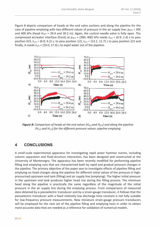
Figure 8 depicts comparison of heads at the end valve sections and along the pipeline for the case of pipeline emptying with two different values of pressure in the air supply line: pHPT = 300 and 400 kPa (head HHPT = 29.4 and 39.2 m). Again, the control needle valve is fully open. The compressed air/water interface (front) at pHPT = {300; 400} kPa needs t0/3 = {0.9; 1.4} s to pass position 0/3, t1/3 = {6.9; 6.2} s, to pass position 1/3, t2/3 = {13.1; 11.7} s to pass position 2/3 and finally, it needs t3/3 = {19.0; 17.4} s to expel water out of the pipeline.
Figure 8: Comparison of heads at the end valves (H3/3 and H0/3) and along the pipeline
(H2/3 and H1/3) for the different pressure values: pipeline emptying
4 CONCLUSIONS
A small‐scale experimental apparatus for investigating rapid water hammer events, including column separation and fluid‐structure interaction, has been designed and constructed at the University of Montenegro. The apparatus has been recently modified for performing pipeline filling and emptying runs that are characterized both by rapid and gradual pressure changes in the pipeline. The primary objective of the paper was to investigate effects of pipeline filling and emptying on head changes along the pipeline for different initial values of the pressure in high‐pressurized upstream end tank (filling) and air supply line (emptying). The higher initial pressure in the upstream end tank produces higher head rise during the filling process. The minimum head along the pipeline is practically the same regardless of the magnitude of the initial pressure in the air supply line during the emptying process. From comparisons of measured data obtained by a piezoelectric transducer and by a strain‐gauge transducer, it follows that the piezoelectric transducer with a fixed relatively low discharge time constant is not fully suitable for low‐frequency pressure measurements. New miniature strain‐gauge pressure transducers will be employed for the next set of the pipeline filling and emptying tests in order to obtain more accurate data that are needed as a reference for validation of numerical models.
JET 21
Experimental investigations of pipeline filling and emptying in a small-scale apparatus
Experimental investigations of pipeline filling and emptying in a small‐scale apparatus 11
References
[1] Q. Hou, et al.: Experimental study of filling and emptying of a large‐scale pipeline, CASA Report 12‐15, Eindhoven University of Technology, The Netherlands, p.p. 1‐40, 2012
[2] A. Malekpour, B.W. Karney: Profile‐induced column separation and rejoining during pipeline filling, Journal of Hydraulic Engineering, ASCE, Vol. 140, Iss. 11, p.p. 040140541‐12, 2014
[3] J.G. Vasconcelos, S.J. Wright, M. Guizani: Experimental investigations on rapid filling of empty pipelines, Report UMCEE‐05‐01, University of Michigan, Ann Arbor, USA, p.p. 1‐53, 2005
[4] J. Laanearu, et al.: Emptying of large‐scale pipeline by pressurized air, Journal of Hydraulic Engineering, ASCE, Vol. 138, Iss. 12, p.p. 1090‐1100, 2012
[5] Q. Hou, et al.: Experimental investigation on rapid filling of a large‐scale pipeline, Journal of Hydraulic Engineering, ASCE, Vol. 140, Iss. 11, p.p. 040140531‐14, 2014
[6] U. Karadžić, V. Bulatović, A. Bergant: Valve‐induced water hammer and column separation in a pipeline apparatus, Strojniški vestnik – Journal of Mechanical Engineering, Vol. 60, Iss. 11, p.p. 742‐754, 2014
[7] U. Karadžić, F. Strunjaš, A. Bergant, R. Mavrič, S. Buckstein: Developments in pipeline filling and emptying experimentation in a laboratory pipeline apparatus, 6th IAHR Meeting of the Working Group Cavitation and Dynamic Problems in Hydraulic Machinery and Systems, Ljubljana, Slovenia, 2015
[8] H.W. Coleman, W.G. Steele: Experimentation and Uncertainty Analysis for Engineers. John Wiley and Sons, 1989

22 JET
Uroš Karadžić, Anton Bergant JET Vol. 11 (2018)Issue 2
12 Uroš Karadžić, Anton Bergant JET Vol. 11 (2018) Issue 2
‐‐‐‐‐‐‐‐‐‐
Nomenclature
(Symbols) (Symbol meaning)
a D e H L p R t Ux V x H
water hammer wave speed pipe diameter, diameter pipe wall thickness head length pressure pipe radius time uncertainty in a measured quantity flow velocity distance along the pipe head rise volume
(Subscripts) f
HPT max
(Subscripts meaning) final high‐pressurized tank maximum
Acknowledgments The authors wish to thank the Slovenian Research Agency (ARRS) and the Ministry of Science, Montenegro (MSM) for their support for this research conducted through the project BI‐ME/14‐15‐016 (ARRS, MSM) and the programme P2‐0162 (ARRS).