Experimental Investigations of Compressed Sandwich ... · PDF fileExperimental Investigations...
13
Experimental Investigations of Compressed Sandwich Composite/Honeycomb Cylindrical Shells A. Muc 1 & A. Stawiarski 1 & P. Romanowicz 1 Received: 5 June 2017 /Accepted: 8 June 2017 /Published online: 30 June 2017 # The Author(s) 2017. This article is an open access publication Abstract This article explains in some details the behaviour of thick, deep cylindrical sandwich panels subjected to compressive loads. In general, experimental results indicated that two different forms of failure have been observed – the first corresponds to the overall buckling and the second to the facesheet wrinkling. The obtained experimentally damages of shells are verified and validated with the use of the FE analysis, 2-D and 3-D both in the linear and non-linear approach. The unidirectional strain gauges were applied to detect the initiation of the overall buckling mode. Keywords Sandwich cylindrical shell . Buckling . Failure analysis . FE modelling . Experimental study 1 Introduction Innovative high performance design of load bearing components/structures/machines is always sought in not only high tech applications. These constructions should be as light as possible while having high stiffness, sufficient strength and some damage tolerance. This requires structurally efficient construction. Structural efficiency can be maximised by using the most efficient and the cheapest materials and finally optimising the structures geometry. To produce an optimum design both these factors need to be considered throughout the design process. Amongst all possible design concepts in composite structures the idea of sandwich construction has become increasingly popular because of the development of man made cellular materials as core materials. Classical sandwich (CS) structures consist of: a pair of thin stiff strong skins (faces, facings or covers), a thick, lightweight core Appl Compos Mater (2018) 25:177–189 DOI 10.1007/s10443-017-9614-8 * A. Muc [email protected] 1 Institute of Machine Design, Cracow University of Technology, Kraków, Poland
-
Upload
truongdung -
Category
Documents
-
view
228 -
download
3
Transcript of Experimental Investigations of Compressed Sandwich ... · PDF fileExperimental Investigations...
Experimental Investigations of Compressed SandwichComposite/Honeycomb Cylindrical Shells
A. Muc1 & A. Stawiarski1 & P. Romanowicz1
Received: 5 June 2017 /Accepted: 8 June 2017 /Published online: 30 June 2017# The Author(s) 2017. This article is an open access publication
Abstract This article explains in some details the behaviour of thick, deep cylindricalsandwich panels subjected to compressive loads. In general, experimental results indicatedthat two different forms of failure have been observed – the first corresponds to the overallbuckling and the second to the facesheet wrinkling. The obtained experimentally damages ofshells are verified and validated with the use of the FE analysis, 2-D and 3-D both in the linearand non-linear approach. The unidirectional strain gauges were applied to detect the initiationof the overall buckling mode.
Keywords Sandwich cylindrical shell . Buckling . Failure analysis . FE modelling .
Experimental study
1 Introduction
Innovative high performance design of load bearing components/structures/machines isalways sought in not only high tech applications. These constructions should be aslight as possible while having high stiffness, sufficient strength and some damagetolerance. This requires structurally efficient construction. Structural efficiency can bemaximised by using the most efficient and the cheapest materials and finallyoptimising the structures geometry. To produce an optimum design both these factorsneed to be considered throughout the design process.
Amongst all possible design concepts in composite structures the idea of sandwichconstruction has become increasingly popular because of the development of manmade cellular materials as core materials. Classical sandwich (CS) structures consistof: a pair of thin stiff strong skins (faces, facings or covers), a thick, lightweight core
Appl Compos Mater (2018) 25:177–189DOI 10.1007/s10443-017-9614-8
* A. [email protected]
1 Institute of Machine Design, Cracow University of Technology, Kraków, Poland

to separate the skins and carry loads from one skin to the other and an adhesiveattachment (the interface) which is capable of transmitting shear and axial loads toand from the core (Fig. 1).
In the last decade a new class of sandwich structures has been developed. They arecalled as functionally gradient materials (FGMs) and distribute the material functionsthroughout the material body to achieve the maximum heat resistance and mechanicalproperties. Both types of structures (classical sandwiches and FGM sandwiches) arecharacterized in the similar manner, i.e. as structures having different properties in thethickness z direction.
Proper analysis of sandwich structures demands a thorough understanding of the mechan-ical behaviour of both the skins and the core. The current (not solved yet) difficulty toovercome is to provide designers with proper methodologies and tools that could enable themto design improved sandwich structures based on advanced knowledge of sandwich behaviourat global and local scales. It relies on our capability to test, identify, control and modelstructural performances. The impressive variety of core and face materials gives new oppor-tunities to design components which have more complex shapes and higher integratedfunctional capabilities but on the other hand it requires refined testing and modelling ap-proaches that should be encouraged by relevant design guidelines.
Now, the finite element method gives an opportunity to model and compute almosteverything but it is very difficult to call it as a practical guideline for designers. In addition todescribe sandwich structure deformation in an accurate way it is necessary to introduce a specialmulti degrees of freedom finite elements since the correct modelling of the structural behaviouris of relevant interest. A broader discussion of those problems is presented in Ref [1].
The primary objective of the paper is to present experimental investigations of compressedcurved cylindrical thick sandwich shells subjected to compressive loads. The experimentalresults are verified with the use of the finite element software package both in the 2-D and 3-D approaches, and in addition the linear variant of the theory is compared with the non-linearone. The theoretical formulation of this problem is discussed in Ref [2]. It is necessary andworth to point out that the used variant of 2D plate/shell theory has a significant influence onthe optimization problems formulated for the sandwich structures. The variety of optimaldesign problems for sandwiches have been formulated and solved by Muc, Zuchara [3] andwe do not intend to dwell on it herein in details.
Compositeface
Compositeface
Fig. 1 The form of the sandwich panel
178 Appl Compos Mater (2018) 25:177–189

Considerable effort has been devoted to the analysis of beams, panels and struts of sandwichconstruction and the results have been summarised in the books of Allen [4] and Plantema [5]but the works in this area are still continued as it is shown in the NASA reports [6, 7].
2 Failure Modes of Sandwich Constructions
In the analysis of sandwich panels different failure modes are observed, which usuallymay condition its load-carrying capacity. It is obvious that the load-carrying capacitydepends on the sandwich materials, the panel dimensions and the structural geometryitself. However, the most common failure modes and their corresponding designequations have been introduced particularly for the beam sandwich structures. Asthe most significant and dominant damage forms of the sandwich structures one canenumerate the following: a) the skin failure in the form of: 1 – tensile failure, 2- intracellular local buckling, 3 – wrinkling buckling resembling local buckling of individualplies in the laminate in the case of delaminations, b) the core failure in the form ofthe core shear failure, c) the failure of the whole structure, i.e. the core and the faces,in the form of: 1 – crushing (usually compressive) failure of the skins and the core, 2– shear crimping failure (usually due to the compression of the whole structure), 3 –overall (global) buckling of the whole construction. It is worth to mention that variousfailure criteria were introduced but they application is rather limited and depends onthe structural geometry. The broader discussion of the individual failure criteria ofsandwich structures and the limitations of them can be found e.g. in Refs [8–11].
Our further attention will be mainly devoted to the description and characterizationof the global failure mode for sandwich structures. However, as it will be demon-strated, using the experimental results, the individual failure modes cannot be treatedseparately, particularly taking into account various geometrical and material imperfec-tions, arising during manufacturing process.
3 Finite Element Analysis
A lot of problems encountered in the numerical FE modeling of sandwich plate andbeam sandwich structures was discussed in Ref [12]. Now, numerical modeling of asandwich structure behaviour is very easy taking into account the FEM softwarepackages capabilities. For our purposes the FE package NISA II was used in twovariants: A) 2-D approach (Fig. 2) – quadrilateral sandwich planar elements (NKTP33) and B) 3-D approach – eight noded hexahedrons for layered laminated compositestructures (NKTP 7). The difference between models A and B depends on theadditional division in the thickness direction in order to model more accurately thestress distribution. However, it does not affect the global structural behaviour in theform of the buckling failure mode. It should be also emphasized that the numericalmodels A and B allows us to conduct the detailed stress analysis inside and/or on thetop and bottoms of the sandwich structural elements in order to study others thanbuckling modes of failure (see the section 2). It will be the objective of further works.
With the aid of the numerical packages it is possible also to conduct the non-linear post-buckling analysis. It will be done using the classical Riks method for the numerical model A.
Appl Compos Mater (2018) 25:177–189 179

The numerical model were comprised of 1137 nodes and 1080 quadrilateral elements. Inthe model B the sandwich thickness was divided into 5 layers; three of them (equally spaced)characterized the core behaviour. Two displacements (except a displacement allowable in thez-direction) and all three rotations were fixed along the bottom edge of the panels. Oneboundary is free, and the last two satisfy symmetry conditions – Fig. 2.
4 Experimental Investigations
In the present work, in-plane compressive performance of glass fiber woven roving cylindricalflat sandwich shells with hexagonal honeycomb core was examined. The critical globalbuckling load of sandwich constructions were tested and compared.
4.1 Materials and Specimens
Regular cellular honeycomb (Nomex - made with aramid fiber paper and coated with phenolicresin) having 5.5 [mm] thickness, 6.35 [mm] cell size and 0.06 [mm] cell-wall thickness was usedas the core materials. The assumed mechanical properties (see Ref. [13]) are given in Table 1.
Epoxy resin and satin-weave glass fiber fabric were used for face (skin) sheets.The sandwich specimens were made with the use of the steel mould. Their dimensions are
presented in Fig. 3. The upper and lower skins of the sandwich were made of three plies ofglass/epoxy. The assembled whole structure of the sandwich were cured under the temperature
Fig. 2 Discretization of the sandwich shell – 2-D model (a quarter of the structure)
Table 1 Mechanical properties of the sandwich components (E3 = 0.1E1, G23 = G13 = 0.6G12)
Material E1 [GPa] E2 [GPa] G12 [GPa] ν12
Core 5.2 3.73 1.85 0.24Face (skin) 13.14 13.14 9.62 0.25
180 Appl Compos Mater (2018) 25:177–189
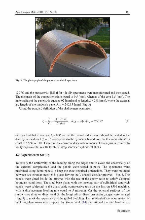
120 °C and the pressure 0.4 [MPa] for 4 h. Six specimens were manufactured and then tested.The thickness of the composite skin is equal to 0.5 [mm], whereas of the core 5.5 [mm]. Theinner radius of the panels r is equal to 92 [mm] and its length L = 248 [mm], where the externalarc length of the sandwich panel RAB = 240.85 [mm] (Fig. 3).
Using the standard definition of the shallowness parameter:
ξ ¼ fD
¼ r 1−cosϕð Þ2rsinϕ
; RAB ¼ ϕ r þ tc þ 2t f� �
=2 ð1Þ
one can find that in our case ξ = 0.36 so that the considered structure should be treated as thedeep cylindrical shell (ξ = 0.5 corresponds to the cylinder). In addition, the thickness ratio t/r isequal to 6.5/92 = 0.07. Therefore, the correct and accurate numerical FE analysis is required toverify experimental results for thick, deep sandwich cylindrical shells.
4.2 Experimental Set Up
To satisfy the uniformity of the loading along the edges and to avoid the eccentricity ofthe external compressive load the panels were tested in pairs. The specimens weremachined using demo panels to keep the exact required dimensions. They were mountedbetween two circular steel (end) plates having the V shaped circular grooves – Fig. 4. Thepanels were glued inside the grooves with the use of the epoxy resin to satisfy clampedboundary conditions. The steel base plates with the inserted pair of cylindrical sandwichpanels were subjected to the quasi-static compressive tests on the Instron 8501 machine,with a displacement loading rate equal to 5 mm/min. On the external surfaces of thesandwiches three unidirectional (in the longitudinal direction) strain gauges were located(Fig. 5) to mark the appearance of the global buckling. That method of the examination ofbuckling phenomena was proposed by Singer et al. [14] and utilized the total load versus
Fig. 3 The photograph of the prepared sandwich specimen
Appl Compos Mater (2018) 25:177–189 181

the axial strain gauge results. The tests were terminated when the external load decreasedalmost to the zero. Three pairs of sandwich constructions were tested.
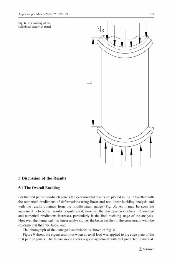
The scheme of loading of sandwich cylindrical panels is presented in Fig. 6 andthe compressive face stress (for one shell) in the axial direction is written as: Nx/(2tf),whereas the total applied to the end steel plate compressive load P is equal to 2φNx.
steelend plate
epoxyresin
core
glass/epoxyfaces
(3 layers)
Fig. 4 Test fixture end cross-section
cylindricalsandwich panel
strain gauges
steel endplate
steel endplate
Fig. 5 Panel and strain gauge locations (the front view)
182 Appl Compos Mater (2018) 25:177–189
5 Discussion of the Results
5.1 The Overall Buckling
For the first pair of sandwich panels the experimental results are plotted in Fig. 7 together withthe numerical predictions of deformations using linear and non-linear buckling analysis andwith the results obtained from the middle strain gauge (Fig. 5). As it may be seen theagreement between all results is quite good, however the discrepancies between theoreticaland numerical predictions increases, particularly in the final buckling stage of the analysis.However, the numerical non-linear analysis gives the better results (in the comparison with theexperiments) than the linear one.
The photograph of the damaged sandwiches is shown in Fig. 8.Figure 9 shows the eigenvector plot when an axial load was applied to the edge plate of the
first pair of panels. The failure mode shows a good agreement with that predicted numerical.
Fig. 6 The loading of thecylindrical sandwich panel
Appl Compos Mater (2018) 25:177–189 183

The linear eigenproblem/eigenvalue solution predicted buckling loads is 8.49% higher than thetest results. It corresponds to the first buckling mode, i.e. m = n = 1. In the final stage of thebuckling the strain gauges shows the drastic increase of strains that, in our opinion, isassociated with the damage of the skin due to the increase of the radial (normal) paneldisplacements.
For cylindrical sandwich shells the overall buckling was predicted by Bert [15] and thevalue of the force P is equal 82.5 [kN]. It is higher than computed numerically.
0 0.1 0.2 0.3
End shortening [mm]
0
20
40
60
Axi
al c
ompr
essi
ve f
orce
[kN
]
ExperimentalStrain gaugeFE linearFE non-linear
Fig. 7 Comparison of the results for the first pair of sandwich panels
Fig. 8 Failure mode of compositesandwiches
184 Appl Compos Mater (2018) 25:177–189

Let us note that the final damage of the panels (Fig. 8) resembles, according to thedefinition introduced in the section 2, the mode b)2, i.e. shear crimping failure. The ultimatecompressive force (shear crimping) resulting to the final damage can be obtained as follows:
Pb;c ¼ tcGcb ð2Þwhere b is the corewidth, tc is the core thickness (Fig. 1) andGc is the core shearmodulus. However,in this case the next failure mode is also possible, i.e. a)1 the tensile failure of the skin Pu:
Pu ¼ t f bσL;u ð3Þwhere tf is the face thickness (Fig. 1) and σL,u is the skin tensile strength. The corresponding to thebuckling load tensile strength is equal to 185.2 [MPa] (evaluatedwith the use of the numericalmodelB). Thus, one can conclude that the final damage takes the form of the global buckling associatedwith the tensile failure of the skin.
5.2 Face Wrinkling
The behaviour and the final failure of the next pairs of sandwich panels is quite different that in thecase discussed previously – understood in the sense of the nonlinearity and a large range of the
Fig. 9 Buckling mode evaluated numerically (a quarter of the panel, linear theory – the model A)
Appl Compos Mater (2018) 25:177–189 185

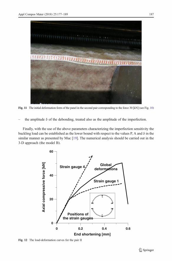
deformation before and after the maxima in the load deformation curves. It may be seen in Fig. 10and by the comparison of Figs. 8 and 11. Face wrinkling is a buckling mode of the skin with awavelength greater than the cell width of the honeycomb. Buckling may occur either in towards thecore or outwards depending on the stiffness of the core in compression and the adhesive strength. Bymodelling the skin as a plate on an elastic foundation Allen [4] estimates the critical compressivestress that results in wrinkling of the top skin. For curved cylindrical shells the evaluation of thecritical buckling loads is much more complicated.
The difference between the load carrying capacity for three pairs of shells reaches 15% (thesecond pair) and 4.8% (the third pair). The values are related to the first pair. Since the wrinklingoccurs for one of the shells in the pairs II and III, the final damage appears for those shells with thewrinkling of the face, in the neighbourhood of the clamped edge.
The details on the efficient and accurate method for predicting sandwich panel facesheetwrinkling are discussed by Zalewski et al. [16] and we shall not dwell on it herein. Bucklinganalysis of debonded cylindrical sandwich panels was also carried out by Sleight and Wang [17].The experimental results obtained for the II and III pairs of sandwiches can be easily interpreted bytaking into account the remarks of Schultz and Nemeth [18]. They demonstrated that for cylindricalpanels buckling results are very sensitive to imperfections. They introduced and adopted again so-called buckling knockdown factors (KDFs) developed byNASA in the 1960s. They pointed out thatthe nature and origin of imperfections lies in the manufacturing process and in this way we can treatthe different failure forms of the studied sandwich cylindrical shells. However, for cylindricalsandwiches the imperfection sensitivity analysis is based on the series of assumptions dealing with:
– the location of the point P where the first debonding between a core and a skin occurs – itis a random value,
– the area and the shape of debonding A in the neighbourhood of the point P,
0 1 2 3
End shortening [mm]
0
20
40
60
Axi
al c
om
pre
ssiv
e fo
rce
[kN
]
Pair IPair IIPair III
Fig. 10 The load-deformation curves obtained from the experiments
186 Appl Compos Mater (2018) 25:177–189
– the amplitude δ of the debonding, treated also as the amplitude of the imperfection.
Finally, with the use of the above parameters characterizing the imperfection sensitivity thebuckling load can be established as the lower bound with respect to the values P, A and δ in thesimilar manner as presented by Muc [19]. The numerical analysis should be carried out in the3-D approach (the model B).
Fig. 11 The initial deformation form of the panel in the second pair corresponding to the force 30 [kN] (see Fig. 10)
0 0.2 0.4 0.6
End shortening [mm]
0
20
40
60
Axi
al c
om
pre
ssiv
e fo
rce
[kN
]
Globaldeformations
Strain gauge 1
1
2
3
4
5
6
Strain gauge 4
Positions ofthe strain gauges
Fig. 12 The load-deformation curves for the pair II
Appl Compos Mater (2018) 25:177–189 187
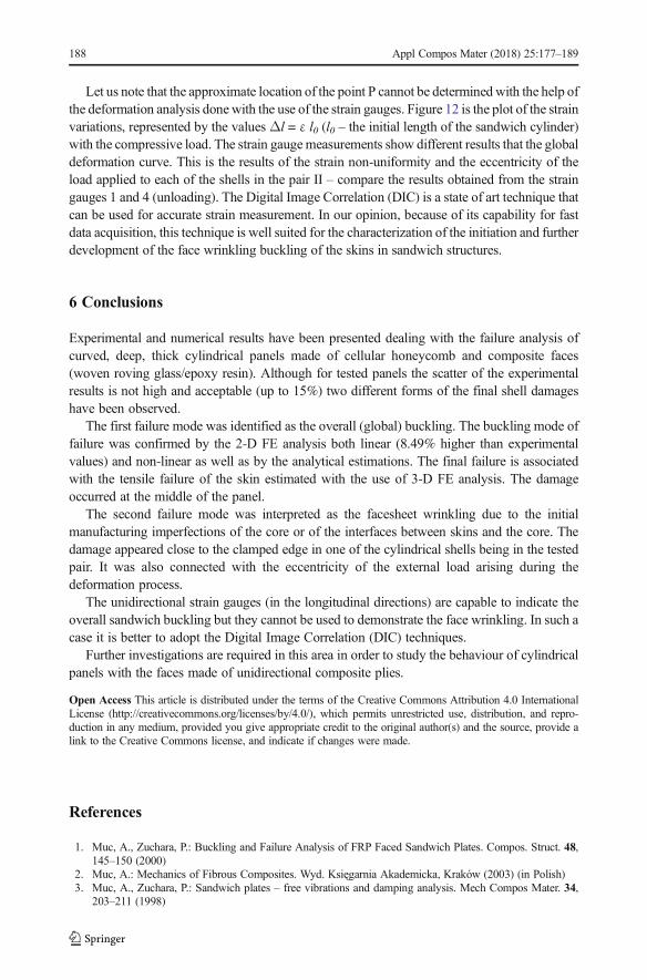
Let us note that the approximate location of the point P cannot be determined with the help ofthe deformation analysis done with the use of the strain gauges. Figure 12 is the plot of the strainvariations, represented by the values Δl = ε l0 (l0 – the initial length of the sandwich cylinder)with the compressive load. The strain gaugemeasurements show different results that the globaldeformation curve. This is the results of the strain non-uniformity and the eccentricity of theload applied to each of the shells in the pair II – compare the results obtained from the straingauges 1 and 4 (unloading). The Digital Image Correlation (DIC) is a state of art technique thatcan be used for accurate strain measurement. In our opinion, because of its capability for fastdata acquisition, this technique is well suited for the characterization of the initiation and furtherdevelopment of the face wrinkling buckling of the skins in sandwich structures.
6 Conclusions
Experimental and numerical results have been presented dealing with the failure analysis ofcurved, deep, thick cylindrical panels made of cellular honeycomb and composite faces(woven roving glass/epoxy resin). Although for tested panels the scatter of the experimentalresults is not high and acceptable (up to 15%) two different forms of the final shell damageshave been observed.
The first failure mode was identified as the overall (global) buckling. The buckling mode offailure was confirmed by the 2-D FE analysis both linear (8.49% higher than experimentalvalues) and non-linear as well as by the analytical estimations. The final failure is associatedwith the tensile failure of the skin estimated with the use of 3-D FE analysis. The damageoccurred at the middle of the panel.
The second failure mode was interpreted as the facesheet wrinkling due to the initialmanufacturing imperfections of the core or of the interfaces between skins and the core. Thedamage appeared close to the clamped edge in one of the cylindrical shells being in the testedpair. It was also connected with the eccentricity of the external load arising during thedeformation process.
The unidirectional strain gauges (in the longitudinal directions) are capable to indicate theoverall sandwich buckling but they cannot be used to demonstrate the face wrinkling. In such acase it is better to adopt the Digital Image Correlation (DIC) techniques.
Further investigations are required in this area in order to study the behaviour of cylindricalpanels with the faces made of unidirectional composite plies.
Open Access This article is distributed under the terms of the Creative Commons Attribution 4.0 InternationalLicense (http://creativecommons.org/licenses/by/4.0/), which permits unrestricted use, distribution, and repro-duction in any medium, provided you give appropriate credit to the original author(s) and the source, provide alink to the Creative Commons license, and indicate if changes were made.
References
1. Muc, A., Zuchara, P.: Buckling and Failure Analysis of FRP Faced Sandwich Plates. Compos. Struct. 48,145–150 (2000)
2. Muc, A.: Mechanics of Fibrous Composites. Wyd. Księgarnia Akademicka, Kraków (2003) (in Polish)3. Muc, A., Zuchara, P.: Sandwich plates – free vibrations and damping analysis. Mech Compos Mater. 34,
203–211 (1998)
188 Appl Compos Mater (2018) 25:177–189
4. Allen, H.G.: Analysis and Design of Structural Sandwich Panels. Pergamon Press, London (1969)5. Plantema, F.J.: Sandwich Construction. John Wiley & Sons, New York (1966)6. Myers, D. E., Pineda, E. J., Zalewski, B.F., Kosareo, D. N., Kellas, S.: Buckling testing and analysis of
honeycomb sandwich panel arc segments of a full-scale fairing barrel. Part 1: 8-Ply In-AutoclaveFacesheets, NASA/TM—2013-217822/PART1 (2013)
7. Pineda, E. J., Myers, D. E., Kosareo, D. N., Zalewski, B.F., Dixon, G.D.: Buckling testing and analysis ofhoneycomb sandwich panel arc segments of a full-scale fairing barrel. Part 2: 6-Ply In-AutoclaveFacesheets, NASA/TM—2013-217822/PART2 (2013)
8. Davies, J.M.: Lightweight Sandwich Construction. Blackwell Science Lta, Osney Mead (2001)9. Hexcel Composites: Honeycomb sandwich design technology. Company Brochure (2000)10. Kuenzi, E.W.: Edgewise compressive strength of panels and Flatwise flexural strength of strips of sandwich
construction, FPL Report 1827 (1951)11. Hu, H., Belouettar, S., Potier-Ferry, M., Daya, E.M.: Review and assessment of various theories for
modeling sandwich composites. Compos. Struct. 84, 282–292 (2008)12. Vautrin, A. (edt):Mechanics of sandwich structures, Proc. Euromech 360Col., KluwerAc. Publ., Dordrecht (1998)13. Roy, R., Park, S.-J., Kweon, J.-H., Choi, J.-H.: Characterization of Nomex honeycomb core constituent
material mechanical properties. Compos. Struct. 117, 255–266 (2014)14. Singer, J., Arbocz, J., Weller, T.: Buckling Experimental Methods in Buckling Thin Walled Structures, Basic
Concepts, Columns, Beams and Plates. John Wiley & Sons, Inc., New York (1998)15. Bert, C.W., Crisman, W.C., Nordby, G.M.: Buckling of Ctlindrical and Conical Sandwich Shells with
Orthotropic Facings. AIAA J. 7, 250–257 (1969)16. Zalewski, B. F., Dial, W. B., Bednarcyk, B. A.: Methods for assessing honeycomb sandwich panel
wrinkling failures, NASA/TM—2012-217697 (2012)17. Sleight, D. W., Wang, J. T.: Buckling analysis of debonded sandwich panel under compression, NASATM
4701, (1995)18. Schultz, M.R., Nemeth, M.P.: Buckling imperfection sensitivity of axially compressed orthotropic cylinders.
Proc. 51st AIAA/ASME/ASCE/AHS/ASC Structures, Structural Dynamics & Materials Conference, AIAApaper no. 2010–2531, Orlando, FL (2010)
19. Muc, A.: Buckling and postbuckling behaviour of imperfect laminated shallow spherical shells underexternal pressure. Composite Structures – VI, pp. 281–296. Elsevier, London (1991)
Appl Compos Mater (2018) 25:177–189 189