EXPERIMENTAL INVESTIGATION ON DIFFERENT PATTERNS OF …
188
EXPERIMENTAL INVESTIGATION ON DIFFERENT PATTERNS OF LASER SURFACE TEXTURING (LST) ON PISTON RING FOR FRICTION POWER REDUCTION IN MULTI CYLINDER I.C. ENGINE A Thesis submitted to Gujarat Technological University for the Award of Doctor of Philosophy in Mechanical Engineering by PATEL VIJAYKUMAR KANTILAL Enrollment No. 139997119012 under supervision of Dr. Bharat M. Ramani GUJARAT TECHNOLOGICAL UNIVERSITY AHMEDABAD, GUJARAT, INDIA NOVEMBER – 2020
Transcript of EXPERIMENTAL INVESTIGATION ON DIFFERENT PATTERNS OF …

EXPERIMENTAL INVESTIGATION ON DIFFERENT
PATTERNS OF LASER SURFACE TEXTURING (LST)
ON PISTON RING FOR FRICTION POWER
REDUCTION IN MULTI CYLINDER I.C. ENGINE
A Thesis submitted to Gujarat Technological University
for the Award of
Doctor of Philosophy
in
Mechanical Engineering
by
PATEL VIJAYKUMAR KANTILAL Enrollment No. 139997119012
under supervision of
Dr. Bharat M. Ramani
GUJARAT TECHNOLOGICAL UNIVERSITY
AHMEDABAD,
GUJARAT, INDIA
NOVEMBER – 2020

EXPERIMENTAL INVESTIGATION ON DIFFERENT
PATTERNS OF LASER SURFACE TEXTURING (LST)
ON PISTON RING FOR FRICTION POWER
REDUCTION IN MULTI CYLINDER I.C. ENGINE
A Thesis submitted to Gujarat Technological University
for the Award of
Doctor of Philosophy
in
Mechanical Engineering
by
PATEL VIJAYKUMAR KANTILAL
Enrollment No. 139997119012
under supervision of
Dr. Bharat M. Ramani
GUJARAT TECHNOLOGICAL UNIVERSITY
AHMEDABAD
NOVEMBER – 2020
i
© PATEL VIJAYKUMAR KANTILAL
ii
DECLARATION
I declare that the thesis entitled “Experimental investigation on different patterns of Laser
Surface Texturing (LST) on piston ring for friction power reduction in multi cylinder
I.C. Engine” submitted by me for the degree of Doctor of Philosophy is the record of
research work carried out by me during the period from 2014 to 2020 under the supervision
of Dr. Bharat M. Ramani (Supervisor) and this has not formed the basis for the award of
any degree, diploma, associateship, fellowship, titles in this or any other University or other
institution of higher learning.
I further declare that the material obtained from other sources has been duly acknowledged in
the thesis. I shall be solely responsible for any plagiarism or other irregularities if noticed in
the thesis.
Signature of the Research Scholar: Date: 26/11/2020
Name of Research Scholar: Patel Vijaykumar Kantilal
Place: Ahmedabad, Gujarat, India.
iii
CERTIFICATE
I certify that the work incorporated in the thesis “Experimental investigation on different
patterns of Laser Surface Texturing (LST) on piston ring for friction power reduction
in multi cylinder I.C. Engine” submitted by Patel Vijaykumar Kantilal was carried out
by the candidate under my supervision/guidance. To the best of my knowledge: (i) the
candidate has not submitted the same research work to any other institution for any
degree/diploma, Associateship, Fellowship or other similar titles (ii) the thesis submitted is a
record of original research work done by the Research Scholar during the period of study
under my supervision, and (iii) the thesis represents independent research work on the part of
the Research Scholar.
Signature of Supervisor: Date: 26/11/2020 Date: 26/11/2020
Name of Supervisor: Dr. Bharat M. Ramani
Place: Rajkot, Gujarat, India
iv
Course-work Completion Certificate
This is to certify that Shri Vijaykumar Kantilal Patel enrolment no. 139997119012 is a
Ph.D. scholar enrolled for the Ph.D. program in the branch Mechanical Engineering of
Gujarat Technological University, Ahmedabad.
(Please tick the relevant option(s))
He has been exempted from the course-work (successfully completed during M.Phil
Course)
He has been exempted from Research Methodology Course only (successfully
completed during M.Phil Course)
He has successfully completed the Ph.D. coursework for the partial requirement for
the award of Ph.D. Degree. His performance in the coursework is as follows
Grade Obtained in Research Methodology
(PH001)
Grade Obtained in Self Study Course
(Core Subject) (PH002)
BB
AB
Supervisor’s Sign
Dr. Bharat M. Ramani
v
Originality Report Certificate
It is certified that Ph.D. Thesis titled “Experimental investigation on different patterns of
Laser Surface Texturing (LST) on piston ring for friction power reduction in multi
cylinder I.C. Engine” by Patel Vijaykumar Kantilal has been examined by us. We
undertake the following:
a. The thesis has significant new work/knowledge as compared already published or are
under consideration to be published elsewhere. No sentence, equation, diagram, table,
paragraph, or section has been copied verbatim from previous work unless it is placed
under quotation marks and duly referenced.
b. The work presented is original and own work of the author (i.e. there is no
plagiarism). No ideas, processes, results, or words of others have been presented as
Author own work.
c. There is no fabrication of data or results which have been compiled/analysed.
d. There is no falsification by manipulating research materials, equipment or processes,
or changing or omitting data or results such that the research is not accurately
represented in the research record.
e. The thesis has been checked using https://turnitin.com plagiarism tool (copy of
originality report attached) and found within limits as per GTU Plagiarism Policy and
instructions issued from time to time (i.e. permitted similarity index <=10%).
Signature of the Research Scholar: Date: 26/11/2020
Name of Research Scholar: Patel Vijaykumar Kantilal
Place: Ahmedabad, Gujarat, India.
Signature of Supervisor:
Name of Supervisor: Dr. Bharat M. Ramani
Date: 26/11/2020
Place: Rajkot, Gujarat, India

vi

vii
Ph.D. THESIS Non-Exclusive License to
GUJARAT TECHNOLOGICAL UNIVERSITY
In consideration of being a Ph.D. Research Scholar at GTU and in the interests of the
facilitation of research at GTU and elsewhere, I, Patel Vijaykumar Kantilal having
Enrollment No.: 139997119012 hereby grant a non-exclusive, royalty-free and perpetual
license to GTU on the following terms:
a) GTU is permitted to archive, reproduce and distribute my thesis, in whole or in part,
and/or my abstract, in whole or in part ( referred to collectively as the “Work”) anywhere
in the world, for non-commercial purposes, in all forms of media;
b) GTU is permitted to authorize, sub-lease, sub-contract or procure any of the acts
mentioned in paragraph (a);
c) GTU is authorized to submit the Work at any National / International Library, under the
authority of their “Thesis Non-Exclusive License”;
d) The Universal Copyright Notice (©) shall appear on all copies made under the authority
of this license;
e) I undertake to submit my thesis, through my University, to any Library and Archives.
Any abstract submitted with the thesis will be considered to form part of the thesis.
f) I represent that my thesis is my original work, does not infringe any rights of others,
including privacy rights, and that I have the right to make the grant conferred by this non-
exclusive license.
g) If third party copyrighted material was included in my thesis for which, under the terms
of the Copyright Act, written permission from the copyright owners is required, I have

viii
obtained such permission from the copyright owners to do the acts mentioned in
paragraph (a) above for the full term of copyright protection.
h) I retain copyright ownership and moral rights in my thesis and may deal with the
copyright in my thesis, in any way consistent with rights granted by me to my University
in this non-exclusive license.
i) I further promise to inform any person to whom I may hereafter assign or license my
copyright in my thesis of the rights granted by me to my University in this non-exclusive
license. j) I am aware of and agree to accept the conditions and regulations of Ph.D. including all
policy matters related to authorship and plagiarism.
Signature of the Research Scholar:
Name of Research Scholar: Patel Vijaykumar Kantilal
Date: 26/11/2020
Place: Ahmedabad, Gujarat, India.
Signature of Supervisor:
Name of Supervisor: Dr. Bharat M. Ramani
Principal, Shri Labhubhai Trivedi Institute
of Engineering and Technology. Kalawad Road - Rajkot.
Date: 26/11/2020
Place: Rajkot, Gujarat, India
Seal:
ix
Thesis Approval Form
The viva-voce of the Ph.D. Thesis submitted by Shri Vijaykumar Kantilal Patel
(Enrollment No. 139997119012) entitled “Experimental investigation on different
patterns of Laser Surface Texturing (LST) on piston ring for friction power reduction
in multi cylinder I.C. Engine” was conducted on Saturday, 07/11/2020 by Gujarat
Technological University through online mode.
(Please tick any one of the following option)
The performance of the candidate was satisfactory. We recommend that he be awarded
the Ph.D. degree.
We recommend that the viva-voce be re-conducted after incorporating the following
suggestions.
Thesis is approved and recommended for the award of Degree
The performance of the candidate was unsatisfactory. We recommend that he should
not be awarded the Ph.D. degree.
(The panel must give justifications for rejecting the research work)
Dr. Bharat M. Ramani Dr.Eng. Medhat Elkelawy
--------------------------------------------------
Name and Signature of Supervisor with Seal
Dr. Sachin Lotan Borse
---------------------------------------------------
External Examiner -1 Name and Signature
Dr. Vineet Kumar Prabhakar
---------------------------------------------------
External Examiner -2 Name and Signature
--------------------------------------------------
External Examiner -3 Name and Signature

x
Abstract
Due to depletion of the natural resources on one hand and an increase in the number of
automobile vehicles, on the other hand, natural fuel may be extincted in the near future.
Reduction in fuel consumption has, therefore, become an extremely important concern for the
automotive industry today. With an increasing demand for greater durability and decreased
oil consumption in an internal combustion engine, it has become necessary to reduce the
power losses to boost engine performance. Engine piston and bore surface finish significantly
influence lubrication oil consumption as well as wear characteristics. More than 40% of
power developed by an internal combustion engine is spent in overcoming the friction and
wear of various components and not only this but these parts are damaged frequently due to
excessive wear, reducing their self life. Therefore, by reducing friction and wear the
performance of the engine can be enhanced, however complete elimination of friction and
wear is not possible. The frictional losses can be reduced by proper selection of lubricating
oil, the material of mating components, and surface microstructure of material used in the
internal combustion engine.
The present work focuses on the friction power reduction by changing the surface
microstructure of piston rings to enhance the performance of the petrol engine with the help
of the Laser Surface Texturing (LST) technique. Laser surface texturing (LST) is mainly used
to reduce the contact surface between the piston and the cylinder. Micro-structure of frictional
surface studied first and accordingly they have been replaced with various texturing patterns.
An experimental set up has been developed with all required instrumentation in order to study
and investigate the effect of LST on engine performance.
Piston ring with dimple textured is designed, fabricated, and used in the motor-driven
engine to study the frictional characteristics and compared with an untextured piston ring.
Therefore this research work presents a detailed study including the fabrication and analysis
of three different patterns made by the Laser Surface Texturing method to see its effect on the
reduction of friction power with different lubrication oils. Each piston ring pattern has been
tested on the developed Maruti 800CC multi-cylinder engine in standard condition. The series
of experiments have been carried out on developed multi-cylinder I.C.Engine test rig under
different speeds. The study includes three different piston ring patterns namely full width,

xi
symmetrically at both sides and centered portion texturing with two various lubricating oils
namely SAE20W40 and SAE20W50. The systematic data has been recorded and observations
have been discussed in the details.
From this detailed study, it has been concluded that there is a substantial reduction in the
friction power of the engine with the use of LST on the piston rings. It is further observed that
with full width texturing on piston ring consumes 26% less power in comparison to non-
textured piston rings and similarly, 15% and 9% respectively in the case of center portion
LST and both sides LST with SAE20W40 lubricating oil. It is further concluded that there is a
definite effect of lubricating oil on the friction power along with LST. With SAE20W50
lubricating oil, the percentage of reduction of friction power for all three LST has been
observed as 29%, 19%, and 10% respectively, that means an additional reduction of 3% in
case of full width LST, 4% with center portion LST and 1% with both sides LST is observed
with SAE20W50.
Due to the reduction in friction between two matching parts in I.C. Engine, it reduces fuel
consumption, increased power output of the engine, reduced oil consumption, and reduction
in exhaust emissions in the engine. It ensures the smooth running of the engine with better
performance and higher thermal efficiency. Brake power is increased by reducing friction
power with the help of LST on piston ring in the I.C. engine which indirectly increases the
thermal efficiency of I.C.Engine.

xii
Acknowledgment
First of all, my deepest gratitude to God almighty for being with me all the time, his
providence, blessings, and guiding me with their divine light. I would like to thank all the
people who made this doctoral study possible. Mentioning all people who deserve my
gratitude without leaving someone out is quite a difficult task, but I will try to do my best.
At the outset, I would like to express my heartfelt gratitude towards my guide and mentor
Dr. Bharat M. Ramani (Supervisor), Professor and Principal, Shri Labhubhai Trivedi
Institute of Engineering and Technology, Rajkot for his invaluable guidance, kind
cooperation, infallible suggestions me throughout the journey of the doctoral research. He has
been a continuous source of motivation, encouragement, inspiration, and moral support
throughout the research work. Thank you will be the very small word against the knowledge
and compassion he bestowed throughout.
I also like to express my deepest gratitude towards the DPC Members, Dr. Pravin P.
Rathod, Professor and In-charge Principal, Government Engineering College, Bhuj, Kutch,
Gujarat, and Dr. Vikas J. Lakhera, Professor & Head, Mechanical Engineering Department,
Nirma University, Ahmedabad, Gujarat for their constant guidance, valuable suggestions and
insightful comments given during throughout all the DPC and Research Weeks. Their
feedback and endless support helped me to work much better. I will also like to extend the
thanks to the entire team of Gujarat Technological University for all their help and support
whenever required.
At this point, I would like to thanks special persons from the industry for their morale &
motivated support in this research, it would not have been possible without, who helped me
to various rigorous work like fabrication, Instrumentation and calibration process, etc for my
experimental setup, providing the separate air-conditioned space for experimental set-up and
to carry out experimental work round the clock for that my sincere thanks go to Mr. Ketul
Patel, Manager, M/S. MODTECH MACHINES PVT. LTD.
I would like to mention the special thanks to Prof. Hiren P. Patel, Dr. Mrunal Chaudhari,
and Dr.P.D.Patel (Assistant Professor, L.D.College of Engineering, Ahmedabad, Gujarat)
for helping me understand technical writing, publication and assisted me whenever I
required. A colleague, Prof. Priyakant A. Vaghela working in my department helped me

xiii
out in proofreading my English before submitting a manuscript and thesis. I would like to
acknowledge his help.
I am grateful to Commissioner of Technical Education (CTE), Gujarat State for granting
permission to pursue a Ph.D. I am also thankful to the Principal and Staff of Mechanical
Engineering Department, Government Polytechnic, Chhotaudepur, and R.C.Technical
Institute, Ahmedabad, for their constant encouragement and support during the tenure of this
research work.
Mr. Rajesh Gajjar, Asst. General Manager, M/S. SAHAJANAND LASER
TECHNOLOGY LTD. G.I.D.C. Gandhinagar, Gujarat, Mr. Jayantilal Patel, Proprietor,
K-Tech Laser. G.I.D.C., Odhav, Ahmedabad, Gujarat for their supports in terms of marking
different patterns of Laser texture on piston rings in their industries.
Special thanks to Dr. Hitesh Panchal Asst. Professor, Government engineering college,
Patan, Gujarat for his untired guidance, great support, and kind advice throughout my
research studies. It was a real privilege and an honor for me to share his exceptional scientific
knowledge but also his extraordinary human qualities.
I would like to express my heartfelt gratitude towards my loving father Kantibhai K Patel,
mother Lalitaben K Patel, my elder brother Shailesh Patel, bhabhi Shushilaben uncle
Bhikhabhai G Patel and aunt Shardaben Pathak for all their endless and unforgettable
efforts to make me an engineer and encouragement they have given throughout my life.
Thank you, Mom & Dad, for encouraging me and providing endless support.
Swati, My wife, who always stood by me, for everything I need. One who always tried to
come up with the solution to any problem I faced throughout this tenure. A thank you will be
a very small word for her. She has been a continuous source of motivation for me.
Special love to my adorable daughter Khushi and son Rudra, who missed my intense
company during this period and for all the maturity they demonstrated through the tenure,
who have taken pains along with me and without which this work would not have seen the
light of success.
At last, I extend my sincere thanks to all those who helped me directly or indirectly in the
research work. Vijay K. Patel
Research Scholar, Gujarat Technological University

xiv
Table of Contents
Declaration II
Abstract X
Acknowledgment
XII
List of Abbreviations
XVIII
List of Symbols
XX
List of Figures XXI
List of Photograph
XXII
List of Tables
XXIII
List of Graphs
XXIV
List of Appendices
XXVIII
Chapter 1 Introduction 1
1.1 Introduction 1
1.2 Research motivation 3
1.3 Laser surface texturing 4
1.3.1 Basic principles 5
1.3.2 Technology application 5
1.3.3 Advantages of LST 5
1.3.4 Applications of LST 6
1.3.4.1 Current applications 6
1.3.4.2 Ideas for future applications 6
1.4 Organization of the thesis 7
Chapter 2 Literature Review 9
2.1 Literature review 9
2.1.1 Laser surface texture on the piston ring 10
2.1.2 Laser surface texture on the cylinder Liner 17
2.1.3 Laser surface texture on the face seal 21
2.1.4 Laser surface texture effect in soft elastohydrodynamic
lubrication 21
2.1.5 Laser surface textured under lubrication initial point
contact 25
2.2 Conclusion of from the literature review 27
2.3 Objective of the present work 27

xv
Chapter 3 Experimental setup 28
3.1 Introduction 28
3.2 Fabrication of test rig 28
3.3 Experimental setup (Test rig) fabrication 29
3.3.1 Engine 29
3.3.2 Variable frequency drive 30
3.3.3 A.C. Motor 30
3.3.4 Digital tachometer 31
3.3.5 Temperature radiation pyrometer 32
3.3.6 Temperature sensor (Thermocouple) 32
3.3.7 Clamp meter 33
3.3.8 Temperature indication device 33
3.3.9 Lubrication oil used for experiment 34
3.4 Experimental methodology 34
3.5 Parameters of LST 35
3.6 Sets of experiment 37
3.7 Experimental procedure 38
3.8 Experimental setup 39
3.9 Locations of nine temperature sensors 40
3.10 Repeatability of experiment 49
3.12 Regression analysis 49
3.13 Uncertainty analysis 49
3.14 Light tightness test 50
Chapter 4 Results and discussion 51
4.1 Experimental observation 51
4.2 Case-I: Both sides portion textured patterns of laser surface
texturing (LST) on piston rings 51
4.2.1 Effect of both sides portion LST on engine temperature
with using SAE20W40 lubrication. 51
4.2.2 Effect of both sides portion LST on lubricating oil
temperature with using SAE20W40 lubrication. 55
4.2.3 Effect of both sides portion LST on bearing temperature
with using SAE20W40 lubrication. 56
4.2.4 Effect of both sides portion LST on friction power with
using SAE20W40 lubrication. 58
4.2.5 Effect of both sides portion LST on engine temperature
with using SAE20W50 lubrication. 59
4.2.6 Effect of both sides portion LST on lubricating oil
temperature with using SAE20W50 lubrication. 63

xvi
4.2.7 Effect of both sides portion LST on bearing temperature
with using SAE20W50 lubrication.
64
4.2.8 Effect of both sides portion LST on friction power with
using SAE20W50 lubrication. 65
4.3 Case-II Center (Middle) portion textured patterns of laser surface
texturing (LST) on piston rings 67
4.3.1 Effect of center (middle) portion LST on engine
temperature with using SAE20W40 lubrication 67
4.3.2 Effect of center (middle) portion LST on lubricating oil
temperature with using SAE20W40 lubrication 71
4.3.3 Effect of center (middle) portion LST on bearing
temperature with using SAE20W40 lubrication. 72
4.3.4 Effect of center (middle) portion LST on friction power
with using SAE20W40 lubrication. 73
4.3.5 Effect of center (middle) portion LST on engine
temperature with using SAE20W50 lubrication. 74
4.3.6 Effect of center (middle) portion LST on lubricating oil
temperature with using SAE20W50 lubrication. 78
4.3.7 Effect of center (middle) portion LST on bearing
temperature with using SAE20W50 lubrication. 79
4.2.8 Effect of center (middle) portion LST on friction power
with using SAE20W50 lubrication. 81
4.4 Case-III Full width textured patterns of laser surface texturing
(LST) on piston rings 83
4.4.1 Effect of full width LST on engine temperature with using
SAE20W40 lubrication 83
4.4.2 Effect of full width LST on lubricating oil temperature with
using SAE20W40 lubrication 87
4.4.3 Effect of full width LST on bearing temperature with using
SAE20W40 lubrication 88
4.4.4 Effect of full width LST on friction power with using
SAE20W40 lubrication 89
4.4.5 Effect of full width LST on engine temperature with using
SAE20W50 lubrication 91
4.4.6 Effect of full width LST on lubricating oil temperature with
using SAE20W50 lubrication 95
4.4.7 Effect of full width LST on bearing temperature with using
SAE20W50 lubrication 96
4.4.8 Effect of full width LST on friction power with using
SAE20W50 lubrication 98
4.5 Effect of different LST texture 99
4.5.1 Effect of different LST patterns at different temperature
locations for various engine speeds 99
4.6
Effect of same LST at different temperature and engine speed for
different lubricating oil 107
4.6.1 Both side LST with SAE20W40 and SAE20W50
lubrication oil 107
4.6.2. Center portion LST with SAE20W40 and SAE20W50
lubrication oil 112

xvii
4.6.3 Full width LST with SAE20W40 and SAE20W50
lubrication oil 117
4.7 Effects of lubrication oil 123
4.7.1 Effect of different LST patterns at different temperature
and engine speeds for SAE20w40 lubricating oil 123
4.7.2 Effect of different LST patterns at different temperature
and engine speeds for SAE20W50 lubricating oil 128
4.8 Comparison of the effects of different LST on power consumed 133
Chapter 5 Conclusion and Future scope 134
Conclusion 134
The scope of future scope 136
List of References 137
List of Appendices
Appendix: A Experimental data 142
Appendix: B Calibration 149
Appendix: C List of materials 155
Appendix: D Measuring instruments parameters 156
Appendix: E List of Publication 157

xviii
List of Abbreviation
Abbreviation Full form
A Rated Output current
A.C. Alternate current
Amb. Ambient
Amp Ampere
ATF Automatic transmission fluid
BDC Bottom dead center
bhp Break horsepower
Bp Axial length of the textured zone
br Ring Width
BSP British standard pipe
c(t) Instantaneous nominal clearance
C.I. Compression Ignition
CC Cubic centimeter
D Cylinder bore
d Ring Diameter
D.C. Direct current
Deg. Degree
DOE Design of Experiments
e Optimum aspect ratio
E Stiffness index
gr Ring end gap
h Instantaneous local film thickness at a specific point (x,z)
HP Horsepower
hp Dimple depth
hr Piston ring height
Hz Hartz
I.C Internal Combustion
i.e. Id est.
ICE Internal combustion engine
IDC Inner dead center
IEC International Electrotechnical commission
IFT Instantaneous Frictional Torque
IMEP Indicated Mean Effective Pressure
IP International Protection
IS Indian Standard oK Temperature (K)
Km Kilometer
KW Kilowatt
L.C. Least count
lit Liter
LST Laser surface texturing
M.Ω Mili Ohm resistance
xix
Abbreviation Full form
m/s Meter per second
Max. Maximum
MEMS Microelectromechanical system
Min. Minimum
mm Millimeter
MPa Mega Pascal
ms microsecond
Mtr meter
N Newton
Nm Newton meter
O.D Outer diameter
ºC Degree Celsius
OFT Oil film thickness
P Cylinder gas pressure
p Instantaneous local hydrodynamic pressure
pe Total external pressure on the ring consisting of gas pressure
and piston ring elasticity
ph Instantaneous average hydrodynamic pressure between the ring
and liner
PM Particulate emissions
PT Platinum
PV Pressure velocity
rc Crankshaft radius
rp Radius of dimple
RPM or rpm Revolution per meter
RTD Resistance Temperature Detector
S.I. Spark Ignition
SAE Society of Automotive Engineers
SATP Standard ambient temperature and pressure condition
SEHL Soft elasto-hydrodynamic laboratory
Sp Dimple Density / Area density of the dimples
STC Series temperature sensor RoHs Certificate
TC Thermocouple
TDC Top dead center
Temp. Temperature
tr Radial Thickness
V Voltage
v/s Versus
VAC Voltage amperage and frequency
VFD Variable frequency drive
W* Piston ring width
X Axial direction of the cylinder liner
Z Circumferential direction of the piston ring.

xx
List of Symbols
Symbols Full form
α The angle between the laser beams.
λ Laser wavelength
µ Dynamic viscosity of the fluid
ϼ Piston ring material density
ω Angular velocity of the crankshaft
xxi
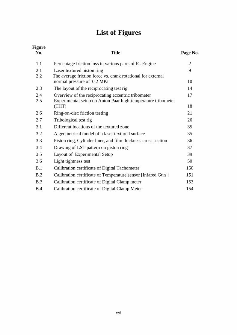
List of Figures
Figure
No. Title Page No.
1.1 Percentage friction loss in various parts of IC-Engine 2
2.1 Laser textured piston ring 9
2.2
The average friction force vs. crank rotational for external
normal pressure of 0.2 MPa 10
2.3 The layout of the reciprocating test rig 14
2.4 Overview of the reciprocating eccentric tribometer 17
2.5
Experimental setup on Anton Paar high-temperature tribometer
(THT) 18
2.6 Ring-on-disc friction testing 21
2.7 Tribological test rig 26
3.1 Different locations of the textured zone 35
3.2 A geometrical model of a laser textured surface 35
3.3 Piston ring, Cylinder liner, and film thickness cross section 36
3.4 Drawing of LST pattern on piston ring 37
3.5 Layout of Experimental Setup 39
3.6 Light tightness test 50
B.1 Calibration certificate of Digital Tachometer 150
B.2 Calibration certificate of Temperature sensor [Infared Gun ] 151
B.3 Calibration certificate of Digital Clamp meter 153
B.4 Calibration certificate of Digital Clamp Meter 154

xxii
List of Photograph
Photograph
No. Photograph detail Page No.
3.1 3-Cylinder petrol engine 29
3.2 A.C. Motor drive 30
3.3 A.C. Motor 30
3.4 Digital tachometer 31
3.5 Temperature radiation pyrometer 32
3.6 Temperature sensor [Thermocouple] 32
3.7 Clamp meter 33
3.8 Temperature indicating device 33
3.9 Photographic view of multi cylinder engine test rig 40
3.10 Variable frequency drive 41
3.11 Assembly of electric motor and engine 41
3.12 Location of temperature Sensor 42
3.13
Internal electric wiring connection of VFD and temperature
sensor 42
3.14 Location of the oil temperature sensor 43
3.15 Piston and piston ring assembly 43
3.16 Un-textured piston ring 44
3.17 Piston ring with laser surface texturing 44
3.18 Temperature display panel and control panel 45
3.19 Speed measuring by the digital tachometer 45
3.20 Engine with 3 piston 46
3.21 Different lubricating engine oil 46
3.22 Removal of piston and piston Ring 47
3.23 Overhauling engine 47
3.24 Preparation of experiment test rig 48
3.25 Photos of actual piston rings with different types of patterns 48
B.1 Digital tachometer 149
B.2 Temperature sensor (Infrared gun) 151
B.3 Photo of the digital clamp meter 152
xxiii
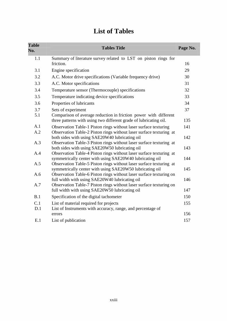
List of Tables
Table
No. Tables Title Page No.
1.1
Summary of literature survey related to LST on piston rings for
friction. 16
3.1 Engine specification 29
3.2 A.C. Motor drive specifications (Variable frequency drive) 30
3.3 A.C. Motor specifications 31
3.4 Temperature sensor (Thermocouple) specifications 32
3.5 Temperature indicating device specifications 33
3.6 Properties of lubricants 34
3.7 Sets of experiment 37
5.1
Comparison of average reduction in friction power with different
three patterns with using two different grade of lubricating oil. 135
A.1 Observation Table-1 Piston rings without laser surface texturing 141
A.2
Observation Table-2 Piston rings without laser surface texturing at
both sides with using SAE20W40 lubricating oil 142
A.3
Observation Table-3 Piston rings without laser surface texturing at
both sides with using SAE20W50 lubricating oil 143
A.4
Observation Table-4 Piston rings without laser surface texturing at
symmetrically center with using SAE20W40 lubricating oil 144
A.5
Observation Table-5 Piston rings without laser surface texturing at
symmetrically center with using SAE20W50 lubricating oil 145
A.6
Observation Table-6 Piston rings without laser surface texturing on
full width with using SAE20W40 lubricating oil 146
A.7
Observation Table-7 Piston rings without laser surface texturing on
full width with using SAE20W50 lubricating oil 147
B.1 Specification of the digital tachometer 150
C.1 List of material required for projects 155
D.1
List of Instruments with accuracy, range, and percentage of
errors 156
E.1 List of publication 157
xxiv
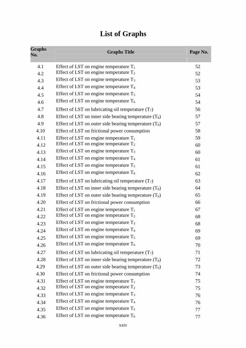
List of Graphs
Graphs
No. Graphs Title Page No.
4.1 Effect of LST on engine temperature T1 52
4.2 Effect of LST on engine temperature T2 52
4.3 Effect of LST on engine temperature T3 53
4.4 Effect of LST on engine temperature T4 53
4.5 Effect of LST on engine temperature T5 54
4.6 Effect of LST on engine temperature T6 54
4.7 Effect of LST on lubricating oil temperature (T7) 56
4.8 Effect of LST on inner side bearing temperature (T8) 57
4.9 Effect of LST on outer side bearing temperature (T9) 57
4.10 Effect of LST on frictional power consumption 58
4.11 Effect of LST on engine temperature T1 59
4.12 Effect of LST on engine temperature T2 60
4.13 Effect of LST on engine temperature T3 60
4.14 Effect of LST on engine temperature T4 61
4.15 Effect of LST on engine temperature T5 61
4.16 Effect of LST on engine temperature T6 62
4.17 Effect of LST on lubricating oil temperature (T7) 63
4.18 Effect of LST on inner side bearing temperature (T8) 64
4.19 Effect of LST on outer side bearing temperature (T9) 65
4.20 Effect of LST on frictional power consumption 66
4.21 Effect of LST on engine temperature T1 67
4.22 Effect of LST on engine temperature T2 68
4.23 Effect of LST on engine temperature T3 68
4.24 Effect of LST on engine temperature T4 69
4.25 Effect of LST on engine temperature T5 69
4.26 Effect of LST on engine temperature T6 70
4.27 Effect of LST on lubricating oil temperature (T7) 71
4.28 Effect of LST on inner side bearing temperature (T8) 72
4.29 Effect of LST on outer side bearing temperature (T9) 73
4.30 Effect of LST on frictional power consumption 74
4.31 Effect of LST on engine temperature T1 75
4.32 Effect of LST on engine temperature T2 75
4.33 Effect of LST on engine temperature T3 76
4.34 Effect of LST on engine temperature T4 76
4.35 Effect of LST on engine temperature T5 77
4.36 Effect of LST on engine temperature T6 77
xxv
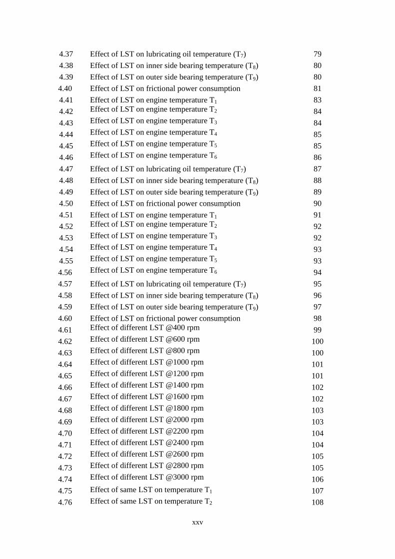
4.37 Effect of LST on lubricating oil temperature (T7) 79
4.38 Effect of LST on inner side bearing temperature (T8) 80
4.39 Effect of LST on outer side bearing temperature (T9) 80
4.40 Effect of LST on frictional power consumption 81
4.41 Effect of LST on engine temperature T1 83
4.42 Effect of LST on engine temperature T2 84
4.43 Effect of LST on engine temperature T3 84
4.44 Effect of LST on engine temperature T4 85
4.45 Effect of LST on engine temperature T5 85
4.46 Effect of LST on engine temperature T6 86
4.47 Effect of LST on lubricating oil temperature (T7) 87
4.48 Effect of LST on inner side bearing temperature (T8) 88
4.49 Effect of LST on outer side bearing temperature (T9) 89
4.50 Effect of LST on frictional power consumption 90
4.51 Effect of LST on engine temperature T1 91
4.52 Effect of LST on engine temperature T2 92
4.53 Effect of LST on engine temperature T3 92
4.54 Effect of LST on engine temperature T4 93
4.55 Effect of LST on engine temperature T5 93
4.56 Effect of LST on engine temperature T6 94
4.57 Effect of LST on lubricating oil temperature (T7) 95
4.58 Effect of LST on inner side bearing temperature (T8) 96
4.59 Effect of LST on outer side bearing temperature (T9) 97
4.60 Effect of LST on frictional power consumption 98
4.61 Effect of different LST @400 rpm 99
4.62 Effect of different LST @600 rpm 100
4.63 Effect of different LST @800 rpm 100
4.64 Effect of different LST @1000 rpm 101
4.65 Effect of different LST @1200 rpm 101
4.66 Effect of different LST @1400 rpm 102
4.67 Effect of different LST @1600 rpm 102
4.68 Effect of different LST @1800 rpm 103
4.69 Effect of different LST @2000 rpm 103
4.70 Effect of different LST @2200 rpm 104
4.71 Effect of different LST @2400 rpm 104
4.72 Effect of different LST @2600 rpm 105
4.73 Effect of different LST @2800 rpm 105
4.74 Effect of different LST @3000 rpm 106
4.75 Effect of same LST on temperature T1 107
4.76 Effect of same LST on temperature T2 108

xxvi
4.77 Effect of same LST on temperature T3 108
4.78 Effect of same LST on temperature T4 109
4.79 Effect of same LST on temperature T5 109
4.80 Effect of same LST on temperature T6 110
4.81 Effect of same LST on lubricating oil temperature T7 110
4.82 Effect of same LST on inner side bearing temperature T8 111
4.83 Effect of same LST on outer side bearing temperature T9 111
4.84 Effect of same LST on temperature T1 112
4.85 Effect of same LST on temperature T2 113
4.86 Effect of same LST on temperature T3 113
4.87 Effect of same LST on temperature T4 114
4.88 Effect of same LST on temperature T5 114
4.89 Effect of same LST on temperature T6 115
4.90 Effect of same LST on lubricating oil temperature T7 115
4.91 Effect of same LST on inner side bearing temperature T8 116
4.92 Effect of same LST on outer side bearing temperature T9 116
4.93 Effect of same LST on temperature T1 117
4.94 Effect of same LST on temperature T2 118
4.95 Effect of same LST on temperature T3 118
4.96 Effect of same LST on temperature T4 119
4.97 Effect of same LST on temperature T5 119
4.98 Effect of same LST on temperature T6 120
4.99 Effect of same LST on lubricating oil temperature T7 120
4.100 Effect of same LST on inner side bearing temperature T8 121
4.101 Effect of same LST on outer side bearing temperature T9 121
4.102 Effect of different LST on temperature T1 123
4.103 Effect of different LST on temperature T2 123
4.104 Effect of different LST on temperature T3 124
4.105 Effect of different LST on temperature T4 124
4.106 Effect of different LST on temperature T5 125
4.107 Effect of different LST on temperature T6 125
4.108 Effect of different LST on lubricating oil temperature T7 126
4.109 Effect of different LST on inner side bearing temperature T8 126
4.110 Effect of different LST on outer side bearing temperature T9 127
4.111 Effect of different LST on temperature T1 128
4.112 Effect of different LST on temperature T2 128
4.113 Effect of different LST on temperature T3 129
4.114 Effect of different LST on temperature T4 129
4.115 Effect of different LST on temperature T5 130
4.116 Effect of different LST on temperature T6 130

xxvii
4..117 Effect of different LST on lubricating oil temperature T7 131
4.118 Effect of different LST on inner side bearing temperature T8 131
4.119 Effect of different LST on outer side bearing temperature T9 132
4.120
Effect on power consumed of various textured surfaces and
without a textured surface
133

xxviii
List of Appendices
Name Title Page No.
Appendix A: Experimental data 142
Appendix B: Calibration 149
Appendix C: List of materials 155
Appendix D: Measuring instruments parameters 156
Appendix E: List of publications 157

1
CHAPTER-1
INTRODUCTION
1.1 Introduction
From the very first moment of birth of any invention, there is always the possibility of
a better way. I.C. engine was invented two centuries back. In these two centuries, more and
more improvements were carried out and this process is continuing. Referring to the
present scenario of the energy crisis and environmental pollution it has become a need, to
check possibilities for improving fuel efficiency by decreasing losses, to make more
environmentally friendly vehicles by decreasing pollutants, and to check options means
alternatives fuel for running an engine.
It is about an energy crisis that needs an enhanced awareness of the use of natural
resources with more cleverly and precipitated an intense study of the efficiency of the
internal combustion engine e.g. the piston assembly, valve train, and engine bearings. Such
studies have remained pulsating and have been further driven by the increasing recognition
of the fragility of our environment and the need to accommodate growth in the automobile
sector in a sustainable manner.
An internal combustion engine is a complicated machine. Hundred of components need
to work together to make it run at all, and many other factors come into play that can cause
a breakdown. Some of the major common engine problems to look out are like engine
knocking and vibration, engine & its joint leaks, stalling and hesitations, engine
overheating, loose or worn out engine parts. The most likely cause of all these phenomena
is due to friction and wear. Friction between the piston and cylinder assemble always plays
a key role in the wear and tear of the IC engine. The wear and tear of components shall
always affect the efficiency as well as the life of the components. By use of cost-effective
methods, it is always feasible to increase the efficiency, productivity, and life of moving
components.
To obtain the maximum efficiency of an engine without any above-mentioned problem,
it is required to reduce this friction force. Engine friction is the primary difference between

2
the energy input of fuel and the energy available on the engine's driveshaft. In an area
where the conservation of fuel increases, the reduction in mechanical friction is the best
way to increase fuel economy without sacrificing the influence of others. In fact, by
decreasing the friction, it can increase the performance by making the fuel energy available
on drive shaft more. By reducing the engine's friction, it can reduce the size of the cooling
and oil systems because a large portion of the friction loss in the engine appears in the
form of heat in the coolant and oil.
After conducting lots of experiments on an engine, scientists are come to know that the
friction forces in an I.C. Engine are in the tune of 17-19 % of total input power. About 45
to 50% (Fig. 1.1) total losses are contributed only by the piston ring assembly system. If
this loss also decreases by 1%, then due to the huge market growth of automotive products,
these efforts can lead to a huge amount of saving of fuel. The Tribological behavior of the
piston ring assembly system should be studied.
FIGURE 1.1: Percentage of friction loss in various parts of IC-Engine [16]
The Piston ring assembly is the heart of an internal combustion engine. The various
tribological factors which can influence the piston ring assembly i.e. piston and ring
materials, piston ring clearance, lubricant properties, piston design, and ring geometry, etc.
So it is required to go into depth to reduce the friction in the piston ring mechanism to
increase efficiency.
The role of piston rings in engines is to dynamically prevent the release of combustion
gas under high pressure and the ingress of lubricant into the combustion chamber. A
modern set of piston rings consists of 2 or 3 rings, namely compression rings, and an oil
control ring. Engine performance is highly dependent on the tribological behavior between
the cylinder liner and the piston ring.
3
The importance of lubricating piston rings has been identified in recent decades.
Numerous researchers have done significant work on this phenomenon when the cylinder-
sleeve of a piston ring is in contact. Of particular interest are the friction forces that occur
at the piston ring cylinder-liner interface, which directly affects the oil consumption and
the efficiency of the internal combustion engine (ICE) system. When relative motion
occurs between mechanical surfaces in contact, friction forces are established that
counteract the motion. Efficiency suffers because the energy used to overcome friction is a
part of the input to the engine that can never be converted into useful work.
1.2 Research motivation
Indian market is open to the world under the global economic development of the
nation. The automobile market has become competitive, more & more people becoming
owners of the vehicles (four/two). Thus, the consumption of scare fuels is also increasing
& also increasing pollution. There are many different types of four-stroke multi-cylinder
diesel or petrol engine automotive four-wheelers are available in a different capacity in the
market with a fuel efficiency of 10km/liter to 20km/liter. Four-stroke petrol vehicles enjoy
the market share more than 70% for domestic, commercial & agriculture purpose. Hence, it
is preferable to select a piston ring system of the same vehicle for the study of piston ring
pair friction in the multi-cylinder engine system.
Fuel consumption coupled with friction is nowadays a especially significant parameter
for the automotive industry with expected legislative requirements on emissions.
Approximately 30% of the largest source of friction losses in an internal combustion
engine is due to a piston/cylinder system, of which 70–80% is in piston rings, so it is
important to optimize. New materials, coatings, and high-tech processes that were
previously considered too expensive in the automobile industries. Proper lubrication and
texture of the surface are key issues in reducing piston/cylinder friction. In recent years,
especially preferred surface textures and laser surface texturing (LST) has become a
promising new friction reduction technology for mechanical components.
Laser surface texturing has many advantages that can potentially save huge amounts of
energy and increase the efficiency of many mechanical systems. The most obvious
advantage is friction reduction. Friction power leads to the loss of power so the new
technologies are required to reduce the friction power. The exact reduction of friction
depends on a variety of variables, including load capacity, micropore geometry, speed, and
materials used.

4
Reducing friction leads to several advantages. First, the energy saved from heat loss
can reduce the application’s power consumption. Secondly, lower friction generates less
heat, thus decreases surface thermal stresses and strains. Finally, a lower friction
coefficient decreases sticking, in a certain system, smaller forces are used to initiate
movement.
Microcavities act as garbage traps, preserving tiny loose particles from the microcracks and
damage that occur. It was found that the wear resistance of the LST-treated component has
a three times improvement in the fatigue life compared to the standard component. Wear
caused by repeated small surface movements, known as abrasive wear, can be substantially
reduced when LST is applied. Experiments have shown that fatigue life has doubled with
LST. These impressive results of the LST show the potential of this technology.
1.3 Laser surface texture
Laser surface texturing (LST) is a surface treatment system used to increase material
tribology. The use of a laser to create patterned microstructures on the surface of materials
can better the load capacity, wear rate, the life of lubricant while reducing coefficients of
friction.
The use of surface irregularities to enhance tribological properties was explored for the
first in the 1960s and introduced in many production techniques. Even though the use of
surface texture engineering in tribological improvements appeared for several years in the
1990s and is still subject to substantial technical advancement, the surface texture
engineering is being studied. Lasers have non-parallel control of the surface microstructure
compared to other surface etching processes and low environmental effects.
Despite the unavoidable wear and loss of friction in countless processes and
appliances, LST technology offers tremendous opportunities for improved productivity and
service life. Furthermore, LST provides incentives in microelectromechanical devices, for
example, to solve limitations.
Surface texturing in general and laser surface texturing in particular has emerged in
recent years as a viable means of enhancing tribological performance. A great deal of
fundamental research work is still going on worldwide, utilizing various texturing
techniques, to explore the benefits of surface texturing and to optimize the texturing forms
and dimensions under various operating condition.
Of all the practical micro-surface patterning methods it seems that laser surface
texturing (LST) offers the most promising concept. This is because the laser is extremely

5
fast, clean to the environment and provides excellent control of the shape and size of the
micro-dimples, which allows realization of optimum designs.
1.3.1 Basic principles [4]
LST is the method of material processing used to create patterned microstructures on a
workpiece contact surface. While it is possible to use different patterns, typical
microstructures are linear grooves, crossed grooves, and circular grooves, similar to
grooves. Such microstructures work in many ways to enhance tribological properties.
The effects listed below operate to varying degrees, depending on several specific
properties of the application.
1. Lubricating viscosity
2. The geometry of micropores.
3. Relative contact speed.
4. Load pressure, etc.
1.3.2 Technology application [4]
Developing specially structured surface microstructures such as abrasive blasting,
reactive ion etching, and ultrasonic treatment can be achieved in many ways. However,
laser technology provides maximum control and accuracy concerning the resulting
geometry. Also, laser ablation does not use chemical reagents and does not generate
significant waste.
To implement laser texturing of the surface, it is necessary to consider several
technological solutions related to equipment and application. These include laser
characteristics, the use of scanning or interference patterns, geometry and pore frequency,
as well as full and partial LST.
1.3.3 Advantages of LST [4]
Reduces metal to metal contact
Could facilitate speed/ performance increase
Reduces friction by up 75%
Wear resistance can be increased by 6 fold in extreme cases
Improves component life & reliability
Longer life in lubricant starvation situations
Improves seizures resistance 2 fold
Reduces power consumption
Allows increased service periods or downsizing

6
Reduces maintenance costs
Helps prevent catastrophic failures
Heat generation can be reduced by 30%
Could pay for itself in a few weeks
1.3.4 Applications of LST [4]
1.3.4.1 Current applications
LST is currently a relatively new area; LST is primarily in the research and small-scale
level. There are currently some industrial uses of LST, such as the proposed use of LST in
a production line of automobile engines and the use of LST in magnetic drives. Also,
several specialized companies will texture the provided parts and seals. There are currently
a lot of investigations related to various applications for commercial use, including:
Mechanical seal
Duo cone seal
Roller bearing thrust ribs
Thrust Bearings
Thrust collars/washers
Water pump seals
Plain & hydrodynamic bearings
Piston rings & other engine components
Surfaces lubricated by water or nonflammable solutions
High-temperature surfaces lubricated by ATF or other low viscosity lubricants
Gas Seals in turbines
Helps reduce fretting corrosion
Magnetic drives
MEMS devices
Engines
Metal forming as a mean for a secondary hydrodynamic lubrication mechanism
which is called micro-pool or micro-plastic hydrodynamic lubrication.
Bone and dental implants with LST surfaces to improve osseointegration
1.3.4.2 Ideas for future applications
As mentioned above, the capacity for LST is enormous due to the number of devices
that are subject to major losses in friction.
Some ideas for future LST applications include:
7
Bearings like Linear and rotary bearing
Storage energy in the flywheel
Activities and sports (skis, skates, games, sledges)
Acceleration of a projectile through a pipe (i.e. satellite launch using an
electromagnetic / railgun)
1.4 Organization of the thesis
The thesis is organized into six chapters. The abstract of the thesis and the keywords are
presented before the contents of the thesis.
Chapter 1 describes the Introduction of friction generated between various parts of
I.C.Engine. The focus is to reduce friction between piston ring assembly by various
techniques which is also the motivation of the research work.
Chapter 2 deals with the Literature review carried out related to the area of laser
surface texturing on different parts of I.C. Engine for friction reduction. The relevant
information derived from the literature review has been summarized which is immensely
helpful for the present research investigation. Consequently, the statement of the problem
is defined.
Chapter 3 outlines the experiment performed for friction power reduction by various
three patterns of LST on the piston ring within selecting the properly conducive
environment for the system. It includes the fabrication of test rig, experiment set-up
specification, the Experimental methodology as per IS -10000. It consists of the different
parameters of LST, the trials required, the experimental procedure used for checking the
friction power consumption by different patterns of laser surface texturing piston rings
used in multi-cylinder I.C.Engine. It covers regression analysis, uncertainty analysis, and
repeatability of the experiment, light tightness test. It also includes the photos related to the
major components and measuring devices used for measuring different parameters during
an experiment conducted on 800CC multi-cylinder I.C. Engine test rig.
Chapter 4 emphasizes the Results & Discussion part of the overall effect of LST on
the friction power with variants of the lubricants. By providing different combinations of
the parameters, the effect of the LST on various described locations on the engine test rig
is observed. This is done by analyzing the graphs for engine speed v/s temperature and
engine speed v/s friction power consumption. There we also address the achievement of
research goals.

8
Chapter 5 includes the extract of research work which is discussed in Conclusion and
future scope. The important outcomes from this work are presented and suggest the future
scope of work.

9
CHAPTER-2
LITERATURE REVIEW
In this chapter, the significant conclusions have been derived from the exhaustive
literature review carried out of the area of different techniques of laser surface texturing &
utilization and their effects on friction. The relevant information derived from the literature
review has been summarized and the needs for the present research investigations have
been defined. Subsequently, the statement of the problem is defined.
2.1 Literature review
In order not to break with recent trends and to find limitations that have to be resolved
in the process of preparing a laser surface texture and texturing effect for engine friction, a
literature review was carried out.
FIGURE 2.1: Laser textured piston ring [5]

10
2.1.1 Laser surface texture on the piston ring
G.Ryk and I.Etsion [1] tested of partial surface texture piston rings. Tested with
practical piston rings and cylindrical liner segments on a revised test rig. Reference was
made to the characteristics of the non-textured traditional cylindrical rings and the
characteristics of the maximum partial rings of the cylindrical LST. The friction tests were
performed with several standard load Fe values relating to a range of nominal contact
pressure from 0.1 to 0.3 MPa. For a standard case with a nominal contact pressure of 0.2
MPa special results were obtained.
FIGURE 2.2: The average friction force (N) v/s the crank rotation (RPM) with an external
normal pressure of 0.2 MPa [1]
For untextured barrel rings and partly LST cylindrical end rings, the average friction
force is seen against the rotational momentum of the crank. The average friction is
therefore expected to increase with both speed and weight, as is the hydrodynamic
lubrication law.
LST has a significant effect on reducing friction compared to non-textured support
rings. The average reference friction obtained from partially LST cylindrical face rings is
about 20-25% lower than the rings of the facial stem, ranging from 500 to 1200 revolutions
per minute throughout the entire speed range. Their conclusion was also that the
percentage difference between the untextured and the partial LST ring is almost
indistinguishable from the negligible touch strain. It is to be noted that the vibration level
of the test rig begins to rise above 900 to 1200, which prevents tests within this range.
Friction checks at 1200 rpm are less reliable than those in the 500-900 rpm range. Finally,
some actual experiments were performed partially on an LST barrel ring, which decreases
friction substantially below 2000 rpm at lower speeds.
This slight advantage of the partial LST vanished absolutely above 2000 rpm. The
barrel shape, which has probably been achieved by trial and error over many years, does

11
not seem to be good for partial LST. The ring gives the face crown a heavy hydrodynamic
effect, which usually conceals the minor hydrodynamic effects of the surface structure at
high speeds. Therefore, a more appropriate contrast between the features of the optimal
untextured barrier shape and the optimum partial LST cylindrical piston rings should be
made in the future with the burning engine test similar to the current rig test.
Approximately 25% of the partial LST piston rings were found to be in lower conflicts.
I.Etsion and E.Share [2] assessed the effect on fuel consumption and exhaust gas
composition of partially laser textured piston rings during the compression ignition I.C.
engine. Dynamometer tests with Ford Transit were naturally placed on the speed of the
engine under roughly half the load conditions for the 2500 cm3 engine. The LST effect was
tested on the engine’s four top piston rings using the following process. In order to
minimize the random effect in the order of the medium per set of rings was evaluated on 3
separate days. Each day, a speed test procedure and a motor speed test procedure were
tested during two separate operations. Three times every operation has been replicated. The
engine was permitted to reach steady-state conditions that normally are reached after 20
minutes at each point.
Cylindrical rings were contrasted with the non-textured relation to standard barrel-
shaped rings and the maximum partial textual laser surface. It was found that the LST
partial piston rings showed a reduction in fuel consumption of up to 4%, while there was
no noticeable change in the composition of the exhaust gases or the smoke level.
Y. Kligerman et al.[3] have developed a theoretical model to investigate the possible
use of partial LST piston rings with a flat surface, in which only one part of the ring
surface width is textured. Partly based on LST dimples so-called "collective" effect, which
usually creates an equal gap between parallel breeding surfaces. The behavior of the
friction force occurs under pressure in the composite film of a liquid and over the time of
the gap. The key parameters of the problem are determined by intensive parametric
research. Best LST parameters are evaluated such as a reduced piston ring contact size, the
density of the texture area, and textured detail. The maximum friction for partial LST
piston rings has been observed to be much less than the optimum full LST ring. The
difference varies from 30% for narrow rings to 55% for wide rings.
The laser surface piston-cylinder device with textured piston rings has been
investigated by Aviram Ronen et al.[4]. To minimize friction between the piston rings and
cylinder liner, the authors explored the potential use of the piston-ring structures as
spherical dimples, which are the entire ring surface of the liner. This shows that the surface

12
can produce major hydrodynamic effects. Large piston ring and the cylindrical liner were
resolved simultaneously with the solution of the Reynolds equation and dynamic equation
to achieve the time difference under all operating conditions. Significant task parameters
were established. It was the region of dimple, the diameter of the dimple, and the height of
dimple. The best micro-growth depth-to-diameter value was found that gives the least
friction force. The friction can be popular by 30% and more.
The impact of a partial laser surface texture on piston-line friction minimizing was
assessed in experimental studies carried out by G.Ryk et al.[5]. In the previous study, a
30% decreased friction can be achieved with the full LST, which uses the entire width of
the piston ring, which acts individually as the micro-hydro-dynamic coils, to create a large
number of micro dimples. The ring is formed only in part by a portion of the width of the
piston in a partial LST that affects the "location" of the dimples, which also provides a
distance comparable to parallel fertility surfaces.
Experimental tests with flat and parallel samples with fractional LST validated the
recently stated hypothetical model and demonstrating the partial gain over complete LST.
Reducing LST friction using piston rings and cylinder liner segments under actual
production conditions is not easy and requires further study.
Conflicts with partial LST could be reduced to approximately 25% compared with the
full LST at the test manipulation speed limit. The friction decrease is further enhanced with
full LST in comparison with this non-textured body by 40 percent. There is the same
decrease in friction with early manipulations and actual experiments on engines with piston
and cylindrical lining. Nevertheless, experiments were carried out with piston rings in the
shape of a barrel and not with cylindrical conformal rings.
A.Ronen et al.[6] impressed by the study of inertial forces, the limited conditions of
the film's action, and pressure on the strength of the friction between the laser texture of
the piston ring and cylinder liner. There are two approaches; the first total dynamic force is
based on equilibrium, which takes into account inertial forces and the effects of
compression of the film due to the set of piston rings and radial velocity, respectively. The
second is the quasi-static equilibrium of the force, which disregards inertia and compresses
the film’s effects. Real-time variations during the engine cycle pressure instead of
continuing constant pressure instead of boundary crisis, the outcome of the first approach
are also being studied. The problem of a quasi-static force balance will deliver reliable
results for both immediate and average friction strength in combination with a reasonable

13
curve-fit and save time. The key issue with this strategy is that it is unable to predict the
time shifts in the gap, raising the slip speed and preserving the gap due to compression.
The overall clearance value is strongly dependent on the pressure change in the
cylinder in real-time during the engine cycle. For the same case of pressure in an
environmental cylinder, the minimum gap value is the same. In the present pressure in the
cylinder, the immediate friction force is less sensitive and the error in the average friction
force is less than 15%.
V. Ezhilmaran et al. [7] studied the experimental and theoretical effects of the laser
pulsation texture in the piston ring in their work. The effect on the surface morphology of
piston ring recesses was studied in laser wavelengths 532 nm and 1064 nm. A 532 nm laser
wavelength was subsequently used to texture dimples with varying sizes and densities of
appearance and surface. The tribological characteristics of textured samples consisting of
dimples with a size, aspect ratio, and area density in the range from 40 to 130 μm, from 0.1
to 0.3 and from 5 to 38%, respectively, were measured experimentally using a
reciprocating tribometer. The results demonstrated that the minimal friction aspect ratio
differs according to the pit size. There was also found that an area density of 16% in all
dimple diameters, relative to other fractions, was low in friction. A decrease of 72 percent
reduction in the cylinder’s liner wear rate was examined with a textured ring of the
appropriate thickness compared to the examined sleeve with a non-textured ring. Using a
theoretical model based upon the Reynolds equivalent, the thickness of the lubricating film
between a textured surface and an untextured counter surface was calculated. An
experimental study was then compared with the results of the theoretical friction
coefficient thickness studies.
In the piston touch simulations of the piston ring cylinder liner, Sorin-Cristian
Vladescu et al.[8] performed an experimental study of the operation of the lubricant. The
aim was to understand and to enhance the performance of the vehicle engine, including the
effects of cavitation, hunger, and surface texture. A modified test set up was used to load a
portion of the piston ring with a laser-fused silica liner textured reciprocal movement. In
order to show the distribution of dyed oil a fluorescence microscope concentrates on a
contact silica sample. The tests were carried out using several geometric shapes of the
texture and orientation, under lubrication conditions with depletion and without
lubrication, when comparing measurement results against those of non-textured links.
From there studied, they can conclude that the corresponding choice surface texture pattern

14
can not only reduce the piston-cylinder liner friction, but also the consumption of car oil. It
must be written that the lubrication transport mechanisms described above should also as a
result of other types of depression, such as porous coatings (provided that they are smaller
than the contact area).
FIGURE 2.3: The layout of the reciprocating test rig.[8]
Nandakumar M. B et al.[9] has proposed the restoration of the laser surface texturing
piston skirt on the main stop side of an old engine compression restore. Textured piston
engine showed a 60% improvement in compression, restoration of engine performance,
and fuel efficiency. Increased compression showed secondary benefits with reduced HC
and CO emissions. The noise from the piston impact was reduced due to the remaining oil
film, which reduces engine noise by 8 decibels. Consumption of engine oil decreased
undoubtedly from 65 to 25 ml per liter.
In the distorted bore of a standardized column ring and with the conservation of a mass
cavitation algorithm, the two-dimensional Reynolds equation is resolved numerically by
Ali Usman and Cheol Woo Park [10]. The relationship of irregularities in mixed
lubrication, axial ring dynamics, variable ring stability, and practical motor oil rheology
shall be considered in the analyzes for the non-axisymmetric textured PRL interface
tribology. The findings indicate that optimized textures of surface enhance the PRL surface
tribology, whereas broad interface textures are harmful. In terms of its texture of the
surface, the transportation of oil into the ignition chamber remains limited.
N. Morris et al.[11] worked on an approved numerical model that was created for
surface analysis texturing in contact with the piston ring of the cylinder liner. The model
uses a two-dimensional Reynolds solution the equation as well as the inclusion of the

15
Greenwood and Tripp boundary friction model. The model is used to exploring the basic
lubrication mechanism of textured surfaces. Understanding surface texturing developed
during this study, it is possible to design and place textured patterns in a piston ring - a
cylinder liner contact. The results showed that friction reduction during surface texturing is
included in the analysis relative to on non-textured surfaces with the same estimated
surface topography. Surface textures produce micro hydrodynamic pressure disturbances
and also reduce the interaction of irregularities between adjacent surfaces due to reduced
contact area.
Haytam Kasem et al.[12] was studied that laser surface texturing is an interesting
opportunity to adapt the surfaces of materials and thus to improve the friction and wear
properties if suitable sizes of texture elements are selected. In this study works, stainless
steel surfaces were laser-textured by two different laser methods, i.e. direct laser
interference mapping using a nanosecond pulsed Nd: YAG laser and optionally ultrashort
pulsed femtosecond Ti: Sa. Then the textured surfaces were studied in terms of their
friction response in a specially designed linear piston lubrication test setup with fully
formulated 15W40 oil. The results show that dimples with a smaller diameter lead to a
significant reduction in the coefficient of friction compared with dimples of larger diameter
and surfaces with a grid surface pattern obtained by a direct laser interference pattern.
B. Podgornik and M. Sedlacek [13] were studied to explore the possibility of using
kurtosis and asymmetry as design parameters to select the optimal texture pattern for
contact surfaces operating under lubrication conditions. Results of this study performed on
a groove and recess with texture surfaces under light load and low sliding speed confirmed
the correlation between kurtosis and asymmetry parameters and friction coefficient. For
textured surfaces increased excess and more negative asymmetry obtained by reducing the
cavity it was found that size, increasing the depth of the cavity and reducing the density of
texture, gives lower friction. Besides, excess and asymmetry were recognized as suitable
parameters to optimize textured surfaces.
Y. Wakuri et al.[14] studied that the tribological phenomenon of sliding surfaces
between piston rings and cylinder liners maybe some of the most difficult in the interior
internal combustion engines and can become even more serious with increase engine
power. Friction between the piston rings and cylinder liners significantly contributes to the
loss of a mechanical power engine. Friction force calculations for a piston ring package
based on the theory of hydrodynamic lubrication. Oil starvation inside the piston ring
package is taken into account when calculating the oil film thickness. The friction

16
characteristics of the piston rings are evaluated with medium friction effective pressure.
Instant friction the piston unit in the engine is measured improved method of floating
liners, which supports the cylinder liner using hydrostatic bearings. Friction characteristics
made clear from analyses and experiments.
M. Priest and C.M. Taylor[15] has reviewed the revised current position regarding
tribological design and friction associated with tribological engine components, with
particular emphasis on surface topography and surface interaction considerations. Much
remains to be done in this important area, and important areas have been identified for
future attention. The nature of surfaces found in a piston assembly, valve system, and
journal bearings of an internal combustion engine and how mathematical models of engine
tribology try to cope with extreme. The complexity of the inclusion brings surface
topography potentially brings. Key areas for future research and design implications
highlighted.
Table 1.1: Summary of literature survey related to LST on piston rings for friction.
Author Year LST Result Variable Parameters
Aviram
Ronen et al.
2001 With spherical
dimples
30 % reduction in
friction.
Entire ring surface in
contact with the
cylinder liner was
textured.
A.Ronen et
al.
2001 Pores textured
“Piston ring”
and “Cylinder
liner” surfaces.
15% reduction in
friction.
Takes into account
inertial forces and the
effects of compression
of the film due to the
set of piston rings and
radial velocity
respectively.
G.Ryk and
I.Etsion
2005 Piston rings with
partial surface
texture.
Partial LST piston
rings exhibited
about 25% lower
friction.
With a range of
nominal contact
pressure from 0.1 to 0.3
MPa and within speed
limit from 500 to 1200
revolutions per minute.
17
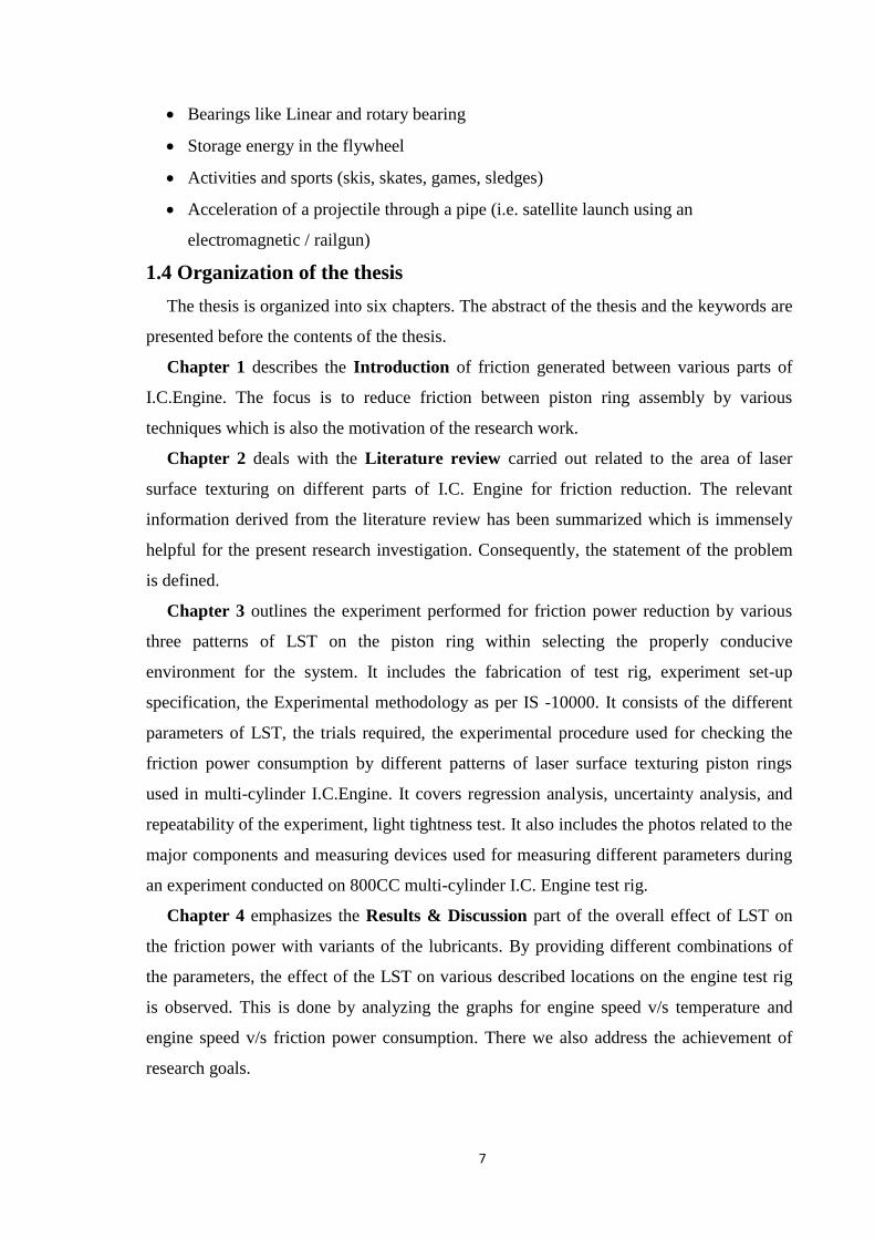
Y. Kligerman
et al.
2005 Full LST ring 30% for narrow
rings to 55% for
wide rings.
The minimum average
friction force for partial
LST piston rings has
been observed to be
much less than the
optimum full LST ring.
G.Ryk et al. 2005 Only a portion
of the piston
ring width is
textured with
high dimple
density.
40% reduction in
friction.
Experiments were
carried out with full
LST piston rings in the
shape of a barrel and
not with conformal
cylindrical rings.
2.1.2 Laser surface texture on the cylinder liner
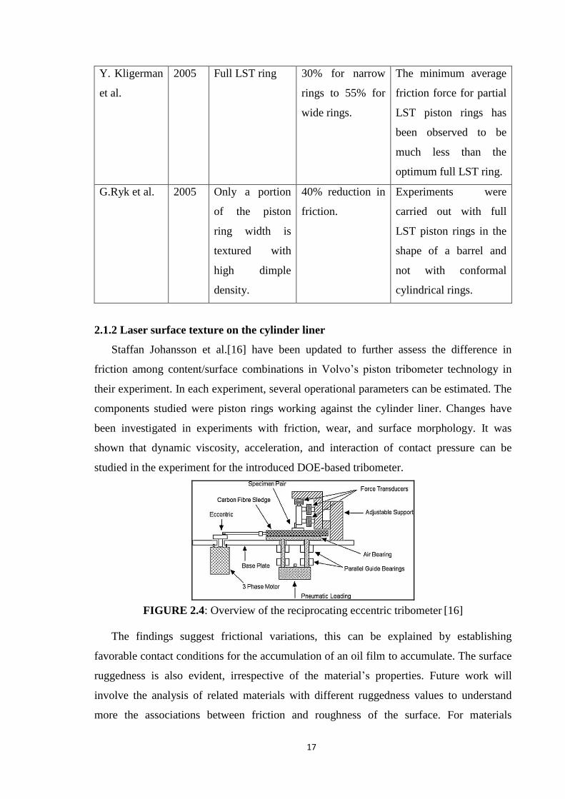
Staffan Johansson et al.[16] have been updated to further assess the difference in
friction among content/surface combinations in Volvo’s piston tribometer technology in
their experiment. In each experiment, several operational parameters can be estimated. The
components studied were piston rings working against the cylinder liner. Changes have
been investigated in experiments with friction, wear, and surface morphology. It was
shown that dynamic viscosity, acceleration, and interaction of contact pressure can be
studied in the experiment for the introduced DOE-based tribometer.
FIGURE 2.4: Overview of the reciprocating eccentric tribometer [16]
The findings suggest frictional variations, this can be explained by establishing
favorable contact conditions for the accumulation of an oil film to accumulate. The surface
ruggedness is also evident, irrespective of the material’s properties. Future work will
involve the analysis of related materials with different ruggedness values to understand
more the associations between friction and roughness of the surface. For materials
18
considered during this study [Gray Cast Iron], the surface ruggedness of mild wear is
apparent, this is exactly for the border and mixed lubrication regime regardless of the
material characteristics. To minimize friction, the entire portion of the surface amplitude is
used. However, the conclusions can be hard to draw about which characteristic of the
surface is most important for friction reduction because of the many surface roughness
parameters, which show a major association with rib.
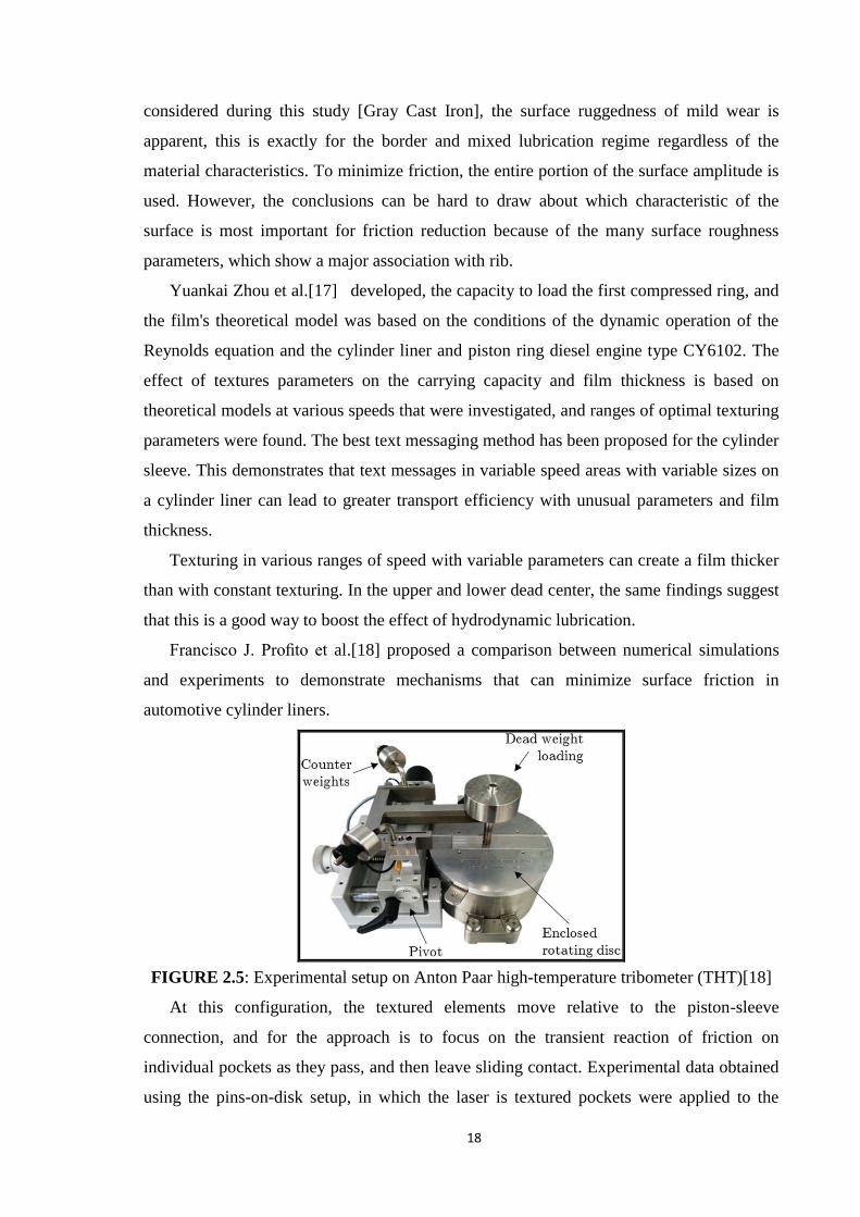
Yuankai Zhou et al.[17] developed, the capacity to load the first compressed ring, and
the film's theoretical model was based on the conditions of the dynamic operation of the
Reynolds equation and the cylinder liner and piston ring diesel engine type CY6102. The
effect of textures parameters on the carrying capacity and film thickness is based on
theoretical models at various speeds that were investigated, and ranges of optimal texturing
parameters were found. The best text messaging method has been proposed for the cylinder
sleeve. This demonstrates that text messages in variable speed areas with variable sizes on
a cylinder liner can lead to greater transport efficiency with unusual parameters and film
thickness.
Texturing in various ranges of speed with variable parameters can create a film thicker
than with constant texturing. In the upper and lower dead center, the same findings suggest
that this is a good way to boost the effect of hydrodynamic lubrication.
Francisco J. Profito et al.[18] proposed a comparison between numerical simulations
and experiments to demonstrate mechanisms that can minimize surface friction in
automotive cylinder liners.
FIGURE 2.5: Experimental setup on Anton Paar high-temperature tribometer (THT)[18]
At this configuration, the textured elements move relative to the piston-sleeve
connection, and for the approach is to focus on the transient reaction of friction on
individual pockets as they pass, and then leave sliding contact. Experimental data obtained
using the pins-on-disk setup, in which the laser is textured pockets were applied to the

19
sample disc. It has been shown that suction absorption, irregularities fluid contact, and
displacement contribute to system response and their relative contribution may vary
depending on the operating mode. Consistency between experimental and model results,
both in terms of the reaction of transitional friction and the formation of cavitation in
pockets, very reassuring and shows that the proposed. The method is capable of capturing
key features that control microtextured contacts. Finally, it was also shown that the micro-
groove samples used in this study have little effect on total friction the answer in
hydrodynamic mode and that, again, the answer to the system in this mode also depends on
various parameters and operating conditions.
Eduardo Tomanik[19] compared the effects of the experiments and the response of
computational modelling, using a one-dimensional computer model to model the effect of
surface texture on the top and oil control rings of the engine cylinder bore. Steady-state,
piston tests, and engine conditions have been considered. To simulate the engine,
simulated conditions close to the top of the turn and in the middle of the course. Various
micro-dimple geometries were considered, as well as full and partial texturing. As the main
thus, micro-depressions on the bore and rings could generate significant hydrodynamic
support with the potential to reduce both frictions and wear. Particular benefits were
predicted when micro-dimples were on the flat surface of the oil control rings.
Zhi-Wei Guo et al.[20] examined that to reduce friction losses in marine diesel engines;
advanced surface textures have provided effective surface treatments. The mechanisms by
which textured patterns and the way texturing is useful remain unclear. To solve this
problem, this article investigates the tribological system of a cylinder liner with a piston
ring (CLPR). Two types of surface textures (Micro concave, Micro V-groove) are
processed on a sample cylinder using various processing methods. A comparative study of
the friction coefficients, texture features of the work surface, and the characteristics of the
oil film is carried out. The results show that the surface texture processing method affects
the performance of CLPR pairs under certain testing conditions. Also, the micro V-groove
is machined using a computer numerical control and precision machining (CNCPM) is
more favourable for improving wear characteristics at low load, while micro concave
treated with chemical etching (CE) is more favourable for improving wear characteristics
at high load. These data help to understand the effect of surface texture on the wear
resistance of CLPR.
Bifeng Yin et al.[21] was analyzed the effect of LST micro-dimples on the lubrication
and frictional properties of the CLPR. On the basis of the average Reynolds equation and
20
the contact equation for irregularities, we developed a new mixed lubrication model. The
model can take into account the effects of coupling between surface roughness, non-
texturing areas, and micro-dimples and the synergistic effect of multi-micro dimples. The
results show that the surface of a cylinder liner using LST can create an effective
hydrodynamic lubrication effect in most regions of the strokes, only near the dead points,
the friction pair is in a mixed state of lubrication, plays the role of contact the main role in
balancing the external load and the friction force of the bumps is obvious. The micro
dimple parameters have been optimized for a better lubrication effect with the following
optimized results: rp= 30–60 μm, Sp= 0.2–0.4, and e = 0.03–0.1.
Khagendra Tripathi et al.[22] was studied that the effectiveness of dimples on friction
and wear resistance, a cylinder of an internal combustion engine (ICE). Dimpled
specimens 150 μm and a dimple density of 13% showed the lowest coefficient of friction
among samples, while samples with a dimple pitch of 200 μm and a density of 7% are set
highest wear resistance. It was also concluded that a textured pattern with a higher Rka and
maximum negative R will reduce the friction coefficient and less wear. The lowest
coefficient of friction was achieved at load 15N within the observed range. The coefficient
of friction textured sample decreases with increasing normal load and the coefficient of
friction can be reduced with increasing sliding speed.
Yeau-Ren Jeng[23] was evaluated the tribological characteristics of plateaus and non-
plateaued surfaces on a tribometer with a pin on the disk. On the disks, a honing pattern of
the engine cylinder bore was modeled. These discs have the same average surface height
with or without a plateau. Friction, wear and scuffing resistance of plateau resistance or
non plateaued disks were evaluated. The results of the “pin on disk” tribometer show that
in the hydrodynamic lubrication mode the plateau has less friction. The author’s findings
also show that surface plateaus tend to have higher wear resistance but lower abrasion
resistance. This also confirms the generally accepted view that the plateau has a shorter
running-in wear period.
L.L.Ting and J.E.Mayer[24] presented in the previous document (Part I Theory), based
on the analytical method comparisons predicted wear curves along the major and minor
axial sides of the cylinder bore manufactured with volumetric sourced from several truck
engines for various vehicles run. An agreement was found to be good. This indicates an
analytical model developed Part I is relevant and suitable for predicting the severity of the
piston ring bore contact for changing engine operating conditions and lubrication. Hence
the need for various parameter changes can be detected so that the wear rate of the cylinder

21
bore can be declining. Wear data, however, it must be available to quantify “Wear”
forecasts. The model may ultimately be useful in optimizing the design engine
components. Since the method is general, it can also be applied to other reciprocating
piston devices such as a gas compressor, Rankine cycle engine or Stirling engine.
2.1.3 Laser surface texture on the face seal
Wan Yi and Xiong Dang-sheng[25] utilized a laser in their research work to produce
micropores on the T8 steel surface and structural characteristics and morphologies of
surface micropores have been observed. Under different loads and speeds, tribological tests
were performed with ring-on-disk testers. It is shown that because of the hydrodynamic
effect of micropores the overall PV value of the mechanical seal can be increased.
FIGURE 2.6: Ring-on-disc friction testing [25]
Laser microporous surface frictional characteristics were evaluated using ring-on-disk
tests corresponding to the contact surface of the mechanical seal at various loads and
speeds. The conclusions are that all surfaces have identical patterns of coefficients of
friction initially reduced and with load and speed increase slowly. The performance of the
microporous laser insulation seal will increase by a factor of 2.5 the maximum PV value
compared with the polished surface.
2.1.4 Laser surface texture effect on soft elastohydrodynamic lubrication
A.Shikarenko et al.[26] was developed a theoretical model to explore the potential use
for a soft elastic elastohydrodynamic laboratory (SEHL) of a laser surface text message in
the form of rounded micro-dimples. This model describes a smooth elastomeric and LST
rigid shared surface, which is progressing simultaneously in the presence of an oily
lubricant. Fluid film pressure distribution and elastomer's elastic distortion, together with
the Reynolds equation, solve and achieves an elastic equation for the elastomer.
The main problem parameters, that is the dimple’s aspect ratio and density of the area
will be defined in a comprehensive parametric analysis. The parametric test provides the
surface structure with the maximum dimensions and supposes that LST increases the

22
carrying capacity efficiently and decreases friction in the SEHL. It has been found that
textured a hard analog creates a bearing capacity that can be maximized by choosing the
recess region Sp’s preferred density and the dimple’s optimum aspect ratio. Total release
parameter lower friction. It was noted that a dimple radius does not affect the tribological
indicators of SEHL.
The best value of the density of the dimple region, Sp, is practically independent of all
other parameters of the problem and is about Sp = 0.3.
The optimal aspect ratio depends solely on the hardness index SEHL, E. When E changes
from 420 to 6 × 10⁵, the optimum aspect ratio (Ɛ)opt varies from 0.1 to 0.02, respectively. A
further increase in E does not affect the optimal aspect ratio, which remains 0.02.
D. B. Hamilton et al.[27] described a fluid lubrication theory applicable to parallel
surfaces such as surfaces of the mechanical seal of a rotating shaft. Introduced a lubrication
mechanism based on surface micro regularities and associated film cavities. Closed-loop
analytics, the resulting solutions give the load capacity as a function of speed, viscosity,
and permeability of the surface sizes. The theoretical results agree qualitatively with load
capacity determined by empirically behind three roughness distributions.
Martin Duarte et al.[28] tested the tribological behavior and service life of lubricant
film improvements on textured material using this new texturing technique. The
mechanical reaction of structures under mixed lubrication conditions is also analyzed.
Several conclusions can be drawn from the results of this study: (1) Laser interference
metallurgy is powerful and fast face texturing method for the manufacture of several types
of periodic arrays with certain geometry on metal substrates. (2) These textured surfaces
can be used to improve the tribological behavior of the target material, especially when
lubrication starvation conditions. (3) Produced structures are strong and sustainable grease
film life, even with mixed grease conditions under which part of the periodic structure is
lost. (4) More experimental data on the dependence of life on the density and depth of the
structure are taken into account. Despite this, more integrated work between construction
geometry, density, depth, and lubrication lifetime of the film must be fulfilled.
I. Krupka et al.[29] studied, the behavior of microstructural surfaces is observed using
formulated lubricant containing polyalcylmethacrylate, improving viscosity index with
boundary film-forming properties. The results show that an increase in film thickness due
to the presence of viscous boundary films is formed within the entire contact, and these
boundary films minimize the local decrease in film thickness caused by microcracks, and
further increase efficiency surface texturing inside non-conformal contacts. From the

23
results obtained, suggested that the combined action of both the formation of the boundary
film and the texturing of the surface combines both contributions, which can help increase
tribological characteristics at different stages of machine parts by an increase in the
thickness of the lubricating film.
Chunxing Gu et al. [30] were studied surface texturing effect in different lubrication
regimes by theoretical analysis. In the adopted model of mixed lubrication, the mass
conservation JFO model has been linked to the statistical asperity contact model using the
concept of load balancing. Textured compound performance studied according to
simulated Stribek curves. According to Stribek curves, the following conclusions may be
received. When the connection is fully lubricated, for conformal contact it is established
that the presence of textures delays the appearance of mixed lubrication model and
boundary lubrication mode. This is a significant advantage for the greased friction pair. For
non-conformal contact, the texture effect is different in different lubrication modes. You
can find that application non-conformal texturing may cause a less positive or even
negative effect on the tribological performance. Surface texturing efficiency depends on
the degree of convergence. Besides, in lubrication due to lack of lubrication, the
connection is easily dependent on the starving degrees. The effect of reducing friction is
observed as unstable.
After discussing the effect of surface texturing on Stribek curves, texture depth, and
distance as texturing options were used to evaluate their impact percentage reduction in
friction. It seems that texturing options are mutually influential on tribological
performance. The determination of the optimal texturing parameters requires a balanced
design with many factors in mind including lubrication mode, lubrication rheology,
working surface texturing conditions, and parameters patterns.
Parul Mishra and P. Ramkumar[31] were paid little attention to studying the effect of a
textured surface on the formation of an additive film. The effect on tribochemical film
additives and their effects on tribological characteristics of the PRCL system are discussed
in the present study. Commercially available steel piston ring and grey cast iron cylinder
liner are used as samples for experiments using linear reciprocating tribometer. The
experiments are carried out at a load of 75N, a frequency of 0.1Hz, and a temperature of
80°C using a polyalphaolefin as base oil mixed with various additives. It has been
established that dimples interfere with the formation of tribochemical films. But the
hydrodynamic effect of dimples improves lubrication performance even with additives.

24
A. Shinkarenko et al.[32] were studied a nonlinear theoretical model for the laser
surface texturing of tribological characteristics with soft elastohydrodynamic lubrication.
Both the geometric and physical nonlinearities of the elastomer are considered using a
logarithmic deformation and constitutional law of Mooney-Rivlin respectively. The results
presented a non-linear model is compared with the previous linear in a wide range of
operating conditions. Found a simpler linear elasticity model predicts results that are only
slightly different from those predicted by more accurate non-linear. Consequently, the
linear elasticity model can be practically considered valid throughout a range of working
conditions.
Xijun Hua et al.[33] were investigated that the technology for combining solid
lubricant and laser surface texturing can significantly improve the tribological properties of
friction pairs. The plate sample was textured with a fiber laser and a composite lubricant of
polyimide (PI) and molybdenum disulfide (MoS2) powders were filled into microbubbles.
Sliding friction characteristics micron-sized composite lubricants and nano-scale
composite lubricants were investigated using a ring tribometer at room temperature to
room temperature 4000C. On the one hand, micron-sized composite greases show that
friction coefficient of textured surface filled with composite lubricant (TS) demonstrates
the lowest level and highest stability compared to a textured surface without solid
lubricant, smooth surface without lubrication, smooth surface polished with a layered
composite solid lubricant. The best dimple density range is 35–46%. Friction coefficients
sample surface filled with micron-composite solid lubricant with texture 35% density is
kept low (about 0.1) at temperatures ranging from RT up to 3000C. On the other hand, the
results of nano-scale composite lubricants show that these friction properties are better than
MoS2-PI micron sizes. Friction coefficients MoS2-PI-CNTs nano-sized composite solid
lubricant below than those of MoS2-PI composite lubricant at temperatures from RT to
4000C. Besides, possible mechanisms involving the synergistic effect of the surface texture
and solid lubricant are discussed in this paper.
Naresh Panchal et al.[34] studied related to engine tribology in an internal combustion
engine. Loss of friction makes up the bulk of about forty-nine percent of the energy
consumed in the engine. Lubricants are used to reduce friction and wear, as well as fuel
consumption, increase engine power output, reduce oil consumption, and reduce exhaust
emissions into the engine. From the analysis of a tribologist, this means an increase in
specific loads, speeds, and temperatures for the main components of engine friction,
namely: a piston assembly, a valve assembly, and thrust bearings, as well as low viscosity
25
motor oils with which they can be lubricated. They reviewed that the most important
parameter in an engine is lubrication, speed and load, and using various methods, such as
mixing engine oil, removing the compression ring, adding additives to the engine oil and
analyzing the assembly of the piston rings that can be obtained control over friction and
wear and the achievement of almost all goals.
Atul Shah et al.[35] made efforts to compare the characteristics of various lubricants
available on the market at various operating parameters on the developed I.C. multi-
cylinder engine test bench. The work set-up on a laboratory scale for measuring
temperature was carried out in a variety of experiments at different locations in an 800CC
multi-cylinder engine system. Experimental tests and observations are carried out in the
range from 600 to 3000 rpm, with specific normal lubricating oil.
Thus, engine performance may vary due to the use of different brands of lubrication oil.
This means that the engine's performance for the tribological parameter (temperature)
varies depending on various lubricants, which proves the importance of choosing the right
lubricant for a particular mechanism, and the potential of the tribological solution remains
to be used.
2.1.5 Laser surface textured under initial contact point lubrication
Andriy Kovalhenko et al.[36] tested and discussed the effect of laser point contact
configuration on tribological properties. The flat dimples were tribological tested on
friction machines using oil with varying viscosities using a disk-pin with a velocity range
of 0.015 to 0.75 m/s. Discs were tested with dimples of various depths and deeper. The
findings show that disc with a high-density yield greater wear because of friction in the
sample of the disk.
However, this high degree of wear created a transition for the rapid production of
contacts and mixed lubrication mode, which rapidly decrease the coefficient of friction
with the ball wear increased. In experiments, the rate of wear in low viscosity oils as
predicated to be higher. Research may be useful for optimizing LST technology for
industrial applications in friction units.
Pingl Lu et al.[37] evaluated the effect of anisotropic shape textures on the behavior of
sliding friction and sensitivity to sliding direction by an experimental study. Plate samples
were textured using triangular inclined dimples using ultra-fast laser surface texturing
technology. Reciprocating cylinder-on-plate tests were carried out with steel sliding pairs
using mineral base oil as a lubricant to compare the tribological characteristics of the
reference non-textured sample and dimpled samples. It was also found that the actual rate

26
of change in contact length is the main factor controlling the reaction of local friction. The
inclined bases of the textures produce the effective action of a converging wedge to create
hydrodynamic pressure and contribute to the general effects of directional friction.
Wen-Zhong Wang et al.[38] was explored the influence of a triangular dimple on the
tribological characteristics of smeared point contacts in various lubrication modes based on
a rotational sliding experiment with a steel disk pattern against smooth steel balls. Arrays
of dimples were produced by the laser method and are characterized by a three-
dimensional profilometer. Test series conducted with various dimple parameters, including
depth, coverage ratio, size, and direction. Streak-like curves were obtained to depict the
lubrication transition modes, and electrical contact resistance was used for quality
characteristics lubrication condition.
FIGURE 2.7: Tribological test rig [38]
Test results showed that dimples on arrays of different sizes, depth, and coating
coefficients had a distinct influence on friction behavior. Compared with non-textured
surfaces when the depth of the dimple decreased from 30 μm to zero with a fixed
coefficient of coating and size, the coefficient of friction first decreased, and then
increased. The friction coefficient finally approached the coefficient of non-textured
surface, during which the lowest value appeared at a dimple depth of approximately 10῀15
μm.
Coverage ratio textures showed a similar effect on the coefficient of friction. Usually
coating a ratio of approximately 10% resulted in the lowest coefficient of friction. Dimple
size and direction also had an obvious effect on the coefficient of friction. Thus, we can
conclude that there is a set of optimal values for the depth of the dimple, coverage ratio,
size, and direction for implementing friction reduction.

27
2.2 Conclusion from the literature review
The conclusion of the laser surface texture on various parts of the I.C. engine from an
extensive literature review is below.
1. Reduce friction up to 40%.
2. Lower fuel consumption up to 4%.
3. More friction reduction in full LST compares to partial LST.
4. Characteristics of the surface that is most important for the reduction of friction.
5. LST improves loading capacity and reducing friction.
6. The wear rate was higher in tests with lower viscosity oils.
2.3 Objectives of the present work
It evolves the very clearly from the above literature survey, there is a need and
potential to study the reduction in friction between piston-cylinder assembly by using
laser surface texturing piston ring in a petrol engine is primary research objective. The
secondary objective of the research is to investigate the reduction in friction power. In this
way, we can increase the power of the engine (output power or brake power), mechanical
efficiency and thermal efficiency, in light of this the following objectives are laid down in
the present research.
1. Identify and numerically quantify the parameters of laser surface texturing and
optimize them for better performance of the internal combustion engine.
2. To design and produce special texture piston rings in order to investigate its effect on
the performance of the internal combustion engine, also study its effect on the
emission.
3. Design, develop and operate the experimental set of multi-cylinder I.C. engine test rig,
equipped with all necessary measuring instruments in order to study the effect laser
surface texturing on the performance of the internal combustion engine.
4. Conduct sets of the experiment with a defined pattern of LST on piston ring with
controlled environment condition and experimentally analysis of the effect LST on
friction power with different type grade of lubrication oil.
5. To study, investigate, and compare the performance of the internal combustion engine
with and without laser surface texturing ring on the piston.
6. To carry out uncertainty analysis of measure quantities/parameters and their effect on
the final result.

28
CHAPTER-3
EXPERIMENTAL SETUP
This chapter describes details of the experiment setup specifications, the experimental
methodology used for different patterns of laser surface texturing piston rings using in
multi-cylinder Internal Combustion Engine. It also includes the regression analysis, the
uncertainty analysis, and the repeatability of the experiment, testing as per IS 10000.
3.1 Introduction
The experimental setup has been designed, developed, and operated on a laboratory
scale to measure various operating parameters like friction power, thermal efficiency, etc.
800CC multi-cylinder engine with all measurement facilities has been used in the present
work. Efforts are put to study the power consumption under, with laser surface texturing
piston ring set, without laser surface texturing piston ring set.
3.2 Experimental of test rig
The Maruti 800CC multi-cylinder internal combustion engine experimental customized
test rig is designed and fabricated for experimentation as a view in Fig. 3.1 to investigate
the impact of surface texture on column compression rings (Top ring and second ring). The
engine is coupled to a variable external electrical motor to measure power consumption.
The power consumption has been measured at various operating parameters, i.e. laser
textured piston ring, engine speed, lubricants, coolant effect at different places in the
piston-cylinder system (TDC, BDC).
The 800CC multi-cylinder internal combustion engine system consists of a crank
mechanism, a piston-cylinder head, and an engine lubrication system; without an engine
cooling system and gearbox. The crankshaft is connected to an induction motor to drive the
engine, as shown in Fig. 3.1 and Fig. 3.2. A variable frequency drive (VFD) is used to
change the speed of the AC motor and measure the power consumed by the engine at
different engine speeds. A tachometer is used to measure the rotational speed of the engine.
Tachometer displays the RPM in a digital number. RTD (Resistance Temperature
Detector/thermocouples) sensors are placed at different nine locations to measure engine
temperature as shown in Fig. 3.1. Sensors T1, T3, and T5 located at 18mm from the top
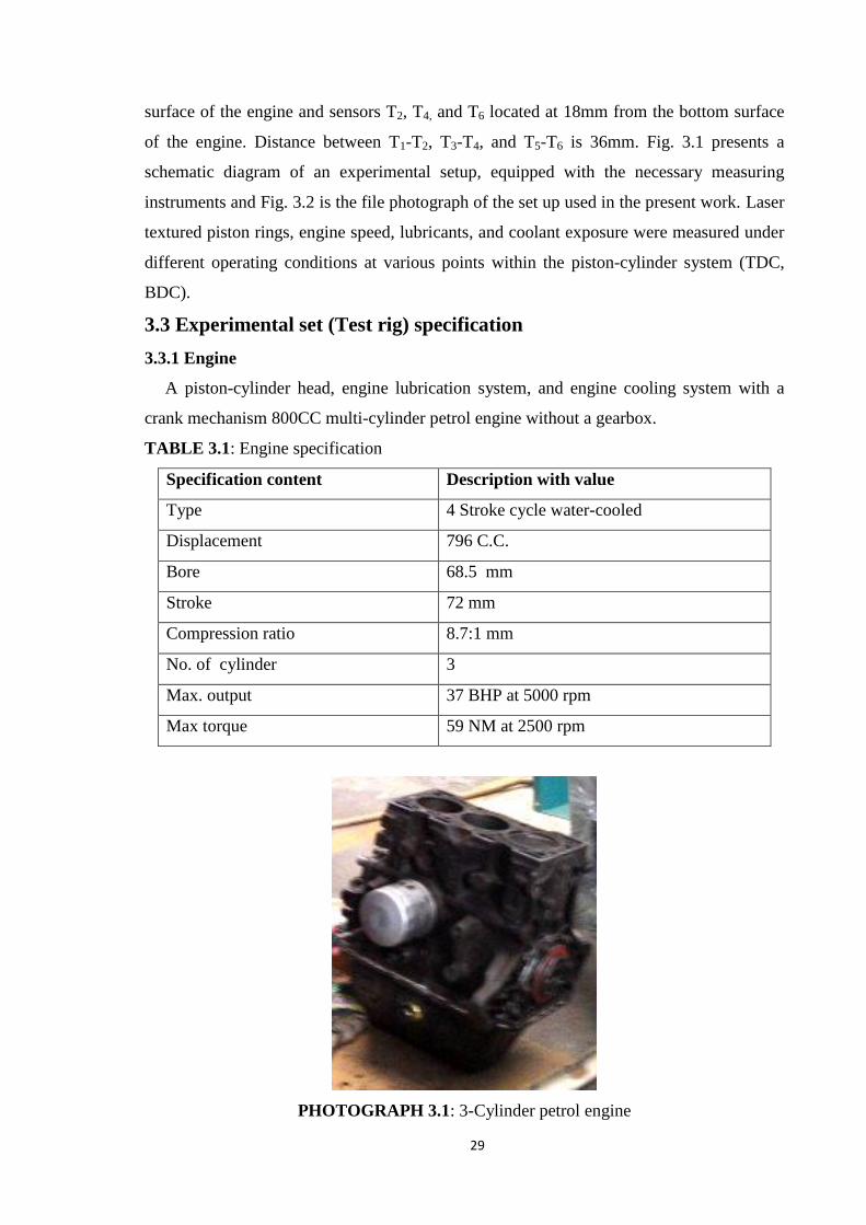
29
surface of the engine and sensors T2, T4, and T6 located at 18mm from the bottom surface
of the engine. Distance between T1-T2, T3-T4, and T5-T6 is 36mm. Fig. 3.1 presents a
schematic diagram of an experimental setup, equipped with the necessary measuring
instruments and Fig. 3.2 is the file photograph of the set up used in the present work. Laser
textured piston rings, engine speed, lubricants, and coolant exposure were measured under
different operating conditions at various points within the piston-cylinder system (TDC,
BDC).
3.3 Experimental set (Test rig) specification
3.3.1 Engine
A piston-cylinder head, engine lubrication system, and engine cooling system with a
crank mechanism 800CC multi-cylinder petrol engine without a gearbox.
TABLE 3.1: Engine specification
Specification content Description with value
Type 4 Stroke cycle water-cooled
Displacement 796 C.C.
Bore 68.5 mm
Stroke 72 mm
Compression ratio 8.7:1 mm
No. of cylinder 3
Max. output 37 BHP at 5000 rpm
Max torque 59 NM at 2500 rpm
PHOTOGRAPH 3.1: 3-Cylinder petrol engine

30
3.3.2 Variable frequency drive
PHOTOGRAPH 3.2: A.C. motor drive
TABLE 3.2: A.C. motor drive specifications (Variable frequency drive)
Specification content Description with value
Model number Altivar ATV312HU40N4
Max. Applicable motor output: 4.0KW-5H.P
Rated output current (A) 13.9 Amp
Input power supply 3-phase 380-400V AC
Frequency(Hz) 50/60
3.3.3 A.C Motor
PHOTOGRAPH 3.3: A.C Motor
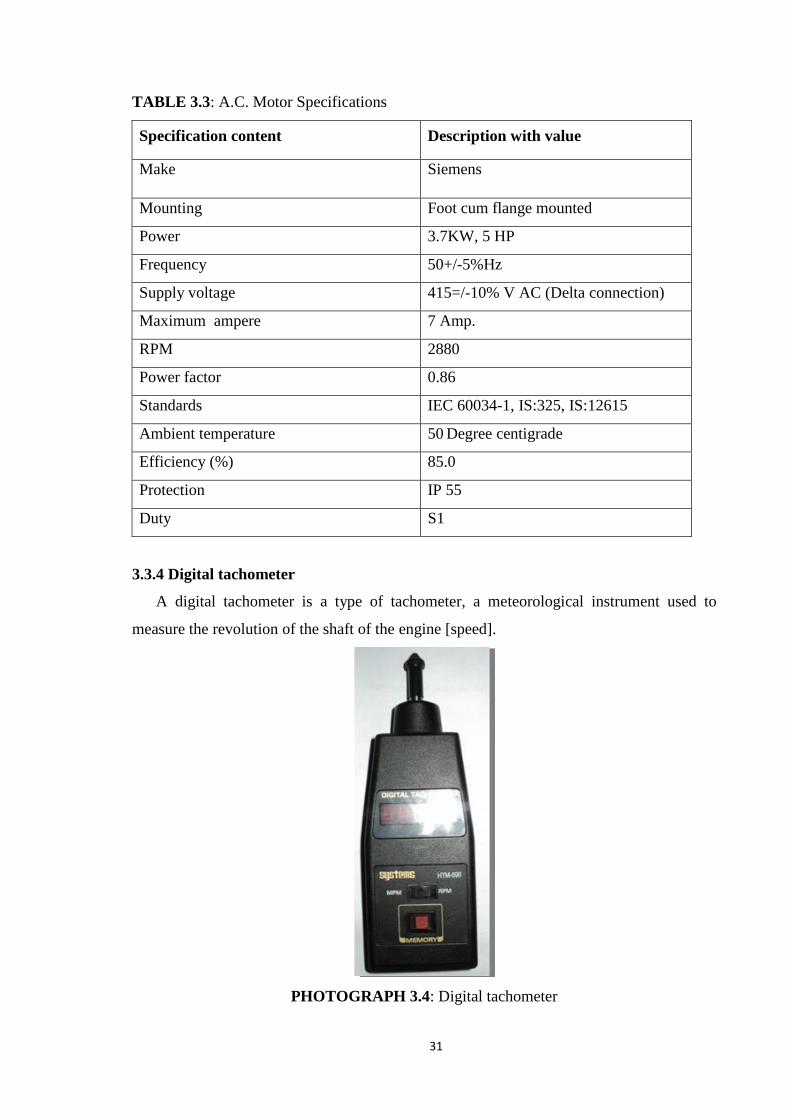
31
TABLE 3.3: A.C. Motor Specifications
Specification content Description with value
Make Siemens
Mounting Foot cum flange mounted
Power 3.7KW, 5 HP
Frequency 50+/-5%Hz
Supply voltage 415=/-10% V AC (Delta connection)
Maximum ampere 7 Amp.
RPM 2880
Power factor 0.86
Standards IEC 60034-1, IS:325, IS:12615
Ambient temperature 50 Degree centigrade
Efficiency (%) 85.0
Protection IP 55
Duty S1
3.3.4 Digital tachometer
A digital tachometer is a type of tachometer, a meteorological instrument used to
measure the revolution of the shaft of the engine [speed].
PHOTOGRAPH 3.4: Digital tachometer

32
3.3.5 Temperature radiation pyrometer
Temperature Pyrometer is a device used for measuring the temperature of the bearing
inside the engine by using the principle of the radiation pyrometer.
Range:- (-) 10oC to 100
oC
PHOTOGRAPH 3.5: Temperature radiation pyrometer
3.3.6 Temperature sensor (Thermocouple)
PHOTOGRAPH 3.6: Temperature sensor (Thermocouple)
TABLE 3.4: Temperature sensor (Thermocouple) specifications:
Specification content Description with value
Make Adinath controls private ltd.
Type RTD (Resistance Temperature Detector) sensor
Code PT 100 –STC
Size 68mm (With Thread Length), O.D.4.7mm -2 Mtr Teflon
(3 Core wire)
Connection ¼” BSP
Material Stainless steel
Range -200 to 850 Deg. centigrade
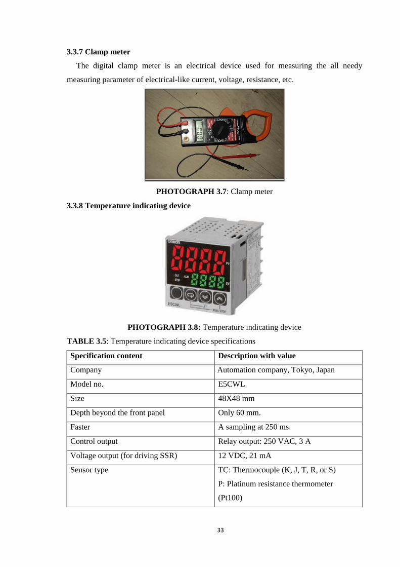
33
3.3.7 Clamp meter
The digital clamp meter is an electrical device used for measuring the all needy
measuring parameter of electrical-like current, voltage, resistance, etc.
PHOTOGRAPH 3.7: Clamp meter
3.3.8 Temperature indicating device
PHOTOGRAPH 3.8: Temperature indicating device
TABLE 3.5: Temperature indicating device specifications
Specification content Description with value
Company OMRON Corporation Industrial Automation company, Tokyo, Japan
Model no. E5CWL
Size 48X48 mm
Depth beyond the front panel Only 60 mm.
Faster A sampling at 250 ms.
Control output Relay output: 250 VAC, 3 A
Voltage output (for driving SSR) 12 VDC, 21 mA
Sensor type TC: Thermocouple (K, J, T, R, or S)
P: Platinum resistance thermometer
(Pt100)
ak

34
3.3.9 Lubrication oil used for the experiment
TABLE 3.6: Properties of lubricants
Sr. No. Name of Lubricant Temperature(0C) Viscosity(cp)
01 Maruti genuine oil
[SAE20W40]
31.8 167.2
40,0 104.4
50.0 64.1
60.0 42.1
70.0 28.9
80.0 20.6
02 Castrol GTX oil
[SAE20W50]
31.8 220.0
40,0 122.2
50.0 74.4
60.0 49.3
70.0 33.7
80.0 24.0
3.4 Experimental methodology
The developed 3-cylinder in-line I.C.Engine set up has been equipped with different
speeds, lubricants, and ring geometry for a series of seven experiments. In this work, the
motorized engine friction test (strip method) is utilized. Experiments have been carried out
at 400 rpm with an increment of 200; the maximum is 3000 rpm.
Initially, the machine operates for at least 5-10 minutes to adequately stabilize and
lubricating oil properly enters the piston ring and cylindrical liner surface. When a stable
state is achieved, the real power consumption, rpm of the engine, and temperature at 8
different positions on the engine are noted with VFD, tachometer, and RTD (Resistance
Temperature Detector) sensors respectively. Then the frequency of the VFD is adjusted to
allow for the next collection of measurements. The motor speed varies by the frequency of
VFD without power switching off. Experiments were conducted in a controlled
environment for specific boundary conditions with the air conditioning room at 23°C as
per standard ambient temperature and pressure conditions (SATP). Increased and rising
motor speeds have been replicated in studies.

35
3.5 Parameters of LST
The following parameters are to be identified and made numerically quantified.
(Assumptions: The dimples are uniformly distributed)
FIGURE 3.1: Different locations of the textured zone
(a) Symmetrically in the center
(b) Symmetrically both ends
FIGURE 3.2: A geometrical model of a laser textured surface
(a) Dimple distribution
(b) Individual cell with a single dimple
Each dimple is modeled by an axis-symmetric spherical segment having a base
radius rp located in the center of an imaginary square cell of sides 2r1 x 2r1.

36
FIGURE 3.3: Piston ring, Cylinder Liner, and film thickness cross-section.
The following optimization parameters to be selected for the study.
Dimple diameter, 2rp = 15 µm
Dimple depth hp= 12 µm
Width of the textured portion of the piston ring, Bp = 0.9 mm
Area density of the dimples, Sp = 0.5
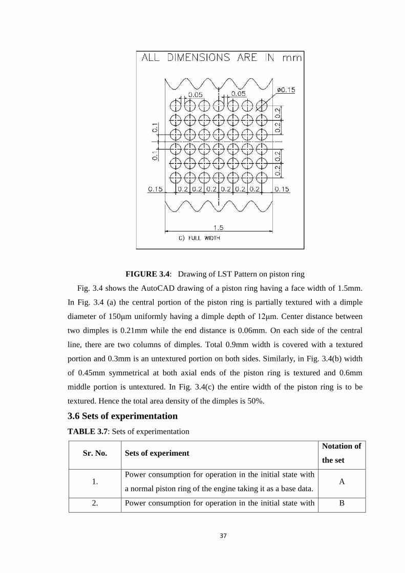
37
FIGURE 3.4: Drawing of LST Pattern on piston ring
Fig. 3.4 shows the AutoCAD drawing of a piston ring having a face width of 1.5mm.
In Fig. 3.4 (a) the central portion of the piston ring is partially textured with a dimple
diameter of 150μm uniformly having a dimple depth of 12μm. Center distance between
two dimples is 0.21mm while the end distance is 0.06mm. On each side of the central
line, there are two columns of dimples. Total 0.9mm width is covered with a textured
portion and 0.3mm is an untextured portion on both sides. Similarly, in Fig. 3.4(b) width
of 0.45mm symmetrical at both axial ends of the piston ring is textured and 0.6mm
middle portion is untextured. In Fig. 3.4(c) the entire width of the piston ring is to be
textured. Hence the total area density of the dimples is 50%.
3.6 Sets of experimentation
TABLE 3.7: Sets of experimentation
Sr. No. Sets of experiment Notation of
the set
1. Power consumption for operation in the initial state with
a normal piston ring of the engine taking it as a base data. A
2. Power consumption for operation in the initial state with B
38
both sides laser surface texturing piston ring with
SAE20W40 lubricating oil.
3.
Power consumption for operation in the initial state with
both sides laser surface texturing piston ring with
SAE20W50 lubricating oil.
C
4.
Power consumption for operation in the initial state with
center portion laser surface texturing piston ring with
SAE20W40 lubricating oil.
D
5.
Power consumption for operation in the initial state with
center portion laser surface texturing piston ring with
SAE20W50 lubricating oil.
E
6.
Power consumption for operation in the initial state with
full width laser surface texturing with SAE20W40
lubricating oil.
F
7.
Power consumption for operation in the initial state with
full width laser surface texturing with SAE20W50
lubricating oil.
G
3.7 Experimental procedure
The test sequences for conducting the experiment work on multi-cylinder internal
combustion engine test rig are as follows.
[1] Study and final selection of the laser surface texturing piston ring set & lubricating oil.
[2] Modification & preparation of the engine for selected piston ring & lubricating oil.
[3] Prepare the foundation of the test rig.
[4] All electrical connections of the test rig, including VFDs and temperature sensors, were
prepared.
[5] Switch ON the power supply and set the frequency on the VFD to the required speed.
[6] Turn on the VFD and ensure the motor and engine is running.
[7] Initially, the system must operate for at least 5-10 minutes for the system to get
stabilized, and lubricating oil properly enters the piston ring and cylindrical liner
surface.
[8] When a stable state is achieved, it records the actual power consumed by the system,
the system speed, as well as the temperature at various nine locations of the engine.

39
[9] For the next measurement, change the frequency on VFD to change the speed of the
system. During the change, there is no need to switch off the power.
[10] To get stabilization of the system, it is to be operated for at least 5 minutes for getting
the next reading.
[11] Repeat the step no 9 & 10 to measure the power consumption for another turn of the
system.
[12] Then turn off the power supply & allow the system to rest condition.
[13] Now repeat the same procedure for the next measurement.
3.8 Experimental setup
FIGURE 3.5: Layout of the experimental setup
1. Electric motor
2. I. C. Engine
3. Electrical panel
4. Variable frequency drive
5. Temperature display device
6. Control panel
7. Electric wiring
8. Coupling
9. Base

40
3.9 Locations of nine temperature sensors
T1 = Temperature sensor at the top dead center for cylinder -1
T2 = Temperature sensor at the bottom dead center for cylinder -1
T3 = Temperature sensor at top dead center for cylinder -2
T4 = Temperature sensor at the bottom dead center for cylinder -2
T5 = Temperature sensor at the top dead center for cylinder -3
T6 = Temperature sensor at the bottom dead center for cylinder -3
T7 = Temperature sensor at the lubricating pan for lubricating oil
T8 = Temperature sensor for inner side bearing temperature
T9 = Temperature sensor for outer side bearing temperature
PHOTOGRAPH 3.9: Photograph of the multi-cylinder engine test rig
Maximum temperature rise at the middle of the stroke length due to friction between
piston rings and cylinder wall and increased piston velocity relative to either the TDC or
BDC. Two sensors are mounted in the middle of the upper half and the lower half of the
stroke length for each cylinder to cover both region of stroke length (Upper half & Lower
half) and to obtain a more precise temperature reading. Both sensors should not be
positioned in the middle of the stroke length.
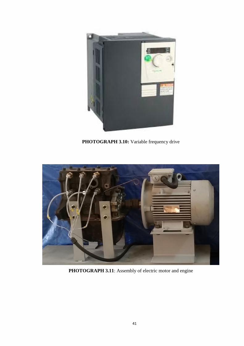
41
PHOTOGRAPH 3.10: Variable frequency drive
PHOTOGRAPH 3.11: Assembly of electric motor and engine

42
PHOTOGRAPH 3.12: Location of the temperature sensor
PHOTOGRAPH 3.13: Internal electric wiring connection of VFD and temperature sensor
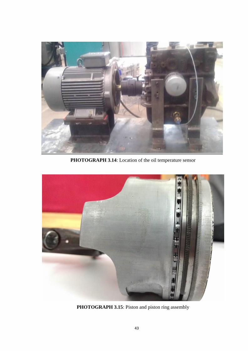
43
PHOTOGRAPH 3.14: Location of the oil temperature sensor
PHOTOGRAPH 3.15: Piston and piston ring assembly

44
PHOTOGRAPH 3.16: Un-textured piston ring
PHOTOGRAPH 3.17: Piston ring with laser surface texturing

45
PHOTOGRAPH 3.18: Temperature display and control panel
PHOTOGRAPH 3.19: Speed measuring by the digital tachometer
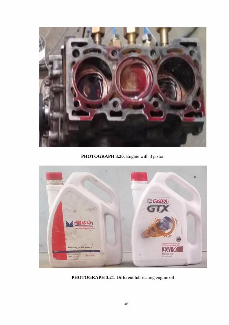
46
PHOTOGRAPH 3.20: Engine with 3 piston
PHOTOGRAPH 3.21: Different lubricating engine oil
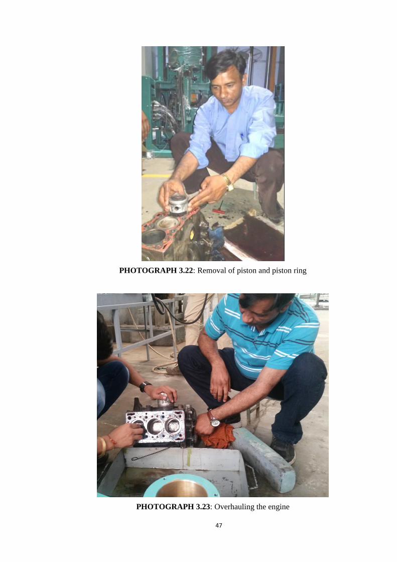
47
PHOTOGRAPH 3.22: Removal of piston and piston ring
PHOTOGRAPH 3.23: Overhauling the engine
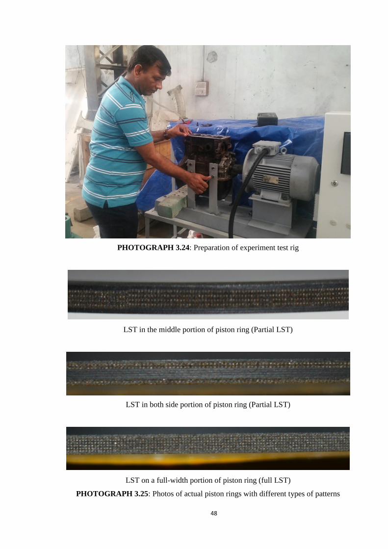
48
PHOTOGRAPH 3.24: Preparation of experiment test rig
LST in the middle portion of piston ring (Partial LST)
LST in both side portion of piston ring (Partial LST)
LST on a full-width portion of piston ring (full LST)
PHOTOGRAPH 3.25: Photos of actual piston rings with different types of patterns

49
3.10 Repeatability of experiment
To ensure the repeatability of the experiments, testing of the engine was done as per the
Indian standard (IS 10000 Part IV), which lays down the guidelines for declaring power,
efficiency, engine speed and specifies relevant correction factors which are required for
adjusting the observed reading to the standard reference condition, as specified in IS:10000
(Part II).
The standard reference conditions are:
Reference pressure Pr = 100 kPa
Reference temperature Tr = 3000K
Reference relative humidity = 0.6
Repeated tests were performed on increasing and decreasing order of engine speed and
no changes were noticed during reading.
3.11 Regression analysis
The experimental data correlated within the mathematical equation below.
Y= P1*X^n
+P2*X^(n-1)
+……..+Pn+1
This equation is 6 degree of the polynomial,
Here Degree of Polynomial n=6 coefficient (it is decided on user accuracy), X=Engine
speed, Y= Friction power
Value of P1=4.04x10⁻¹⁹
, P2= -3.99x10⁻¹⁵
, P3= 1.562x10⁻¹¹
, P4=- 3.05x10⁻⁸,
P5=3.11x10⁻⁵
,
P6= -0.0145, P7=3.928,
The response surface regression method has been implemented for the Design of
Experiment.
The conclusion of the result is the experiment model reliable=97.93%, Speed is significant
because of the p-value of speed=0.0001
3.12 Uncertainty analysis
The uncertainty in measurement is estimated based on the procedure given by J P
Holman. The uncertainty in measurement is defined as
R is the result of which uncertainty is to be estimated. ωR is the uncertainty in the result.
Vi (i = 1 to n) are the variables of which R is a function.
Defining the uncertainty in percentage, the equation modifies to
22
2
2
2
1
1
....
n
n
Rv
R
v
R
v
R
%100....1
22
2
2
2
1
1
n
n
R
v
R
v
R
v
R
RR

50
The uncertainties in the measurement were estimated from the resolution of the
instrument or provided by the manufacturer.
The uncertainty in temperature measurement by thermocouple = +0.01ºC
The uncertainty in rpm measurement by tachometer = +1 rpm
The uncertainty in power measurement by VFD =+0.081%
The uncertainty in length measurement (Wire and thread) = +0.01m
The uncertainty in frequency measurement by VFD = +0.01HZ
3.13 Light tightness test
This test was performed to check the clearance between the piston ring and the cylinder
wall.
FIGURE 3.6: Light tightness test
As per IS/ISO code: 6621-1 (2007), as shown in Fig. 3.6 in this test Light impacted on
the piston ring and cylinder matching area. When we observed on the other side of the
cylinder no light can found so, This proves that, no clearance between the piston ring edge
and the cylinder wall.

51
CHAPTER-4
RESULTS AND DISCUSSION
4.1 Experimental observations
The experimental setup and procedure followed were discussed in the previous chapter.
Experimentally observed readings for power consumption, under different engine
speeds with normal piston ring and laser surface texturing piston ring are recorded.
As per literature review friction losses at the piston-cylinder assembly system are
maximum, which means power consumption with this piston-cylinder assembly system
will also be maximum in compression to the other friction generating system power
consumption. So this is important to understand the contribution of frictional power losses
by a piston ring at different speeds during normal and laser surface texturing piston ring,
the following results were obtained.
The power consumed by the engine was recorded with a normal piston ring and laser
surface texturing piston ring at a different speed.
The temperatures of the system at different nine locations are recorded.
4.2 Case-I: Both sides textured patterns of laser surface texturing (LST)
on piston rings
4.2.1 Effect of both sides LST on engine temperature with using SAE20W40
lubricating oil.
In case-1 part-I, graphs 4.1 to 4.6 are represented the effect of both side laser surface
textures of the piston rings on engine temperature with using SAE20W40 lubricating oil.
These graphs are indicated the comparison of engine speed (rpm) and temperature (0C)
at different six locations without LST (black circle line) and with LST piston ring (white
circle line).

52
Both sides LST with SAE20W40 lubricating oil
ENGINE SPEED [ RPM ]
0 500 1000 1500 2000 2500 3000 3500
TE
MP
ER
AT
UR
E
T1
[ 0
C ]
35
40
45
50
55
60
65
70
WITHOUT LST
WITH LST
Graph 4.1: Effect of LST on engine temperature T1
Both sides LST with SAE20W40 lubricating oil
ENGINE SPEED [ RPM ]
0 500 1000 1500 2000 2500 3000 3500
TE
MP
ER
AT
UR
E
T2
[ 0
C ]
30
40
50
60
70
80
90
WITHOUT LST
WITH LST
Graph 4.2: Effect of LST on engine temperature T2
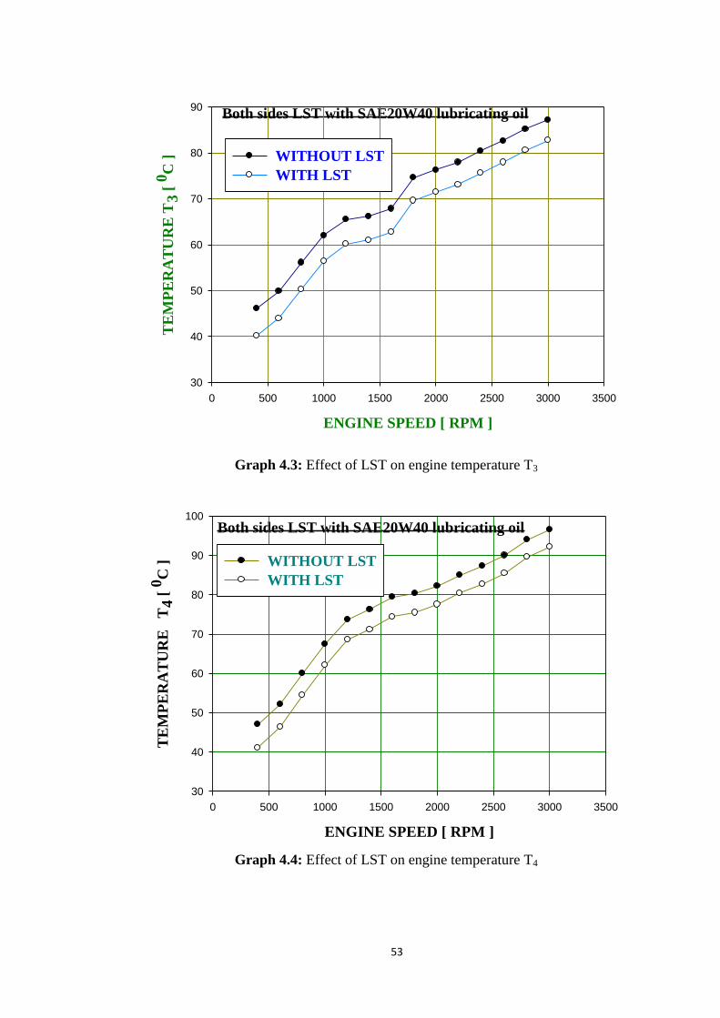
53
Both sides LST with SAE20W40 lubricating oil
ENGINE SPEED [ RPM ]
0 500 1000 1500 2000 2500 3000 3500
TE
MP
ER
AT
UR
E T
3 [
0C
]
30
40
50
60
70
80
90
WITHOUT LST
WITH LST
Graph 4.3: Effect of LST on engine temperature T3
Both sides LST with SAE20W40 lubricating oil
ENGINE SPEED [ RPM ]
0 500 1000 1500 2000 2500 3000 3500
TE
MP
ER
AT
UR
E
T4
[ 0
C ]
30
40
50
60
70
80
90
100
WITHOUT LST
WITH LST
Graph 4.4: Effect of LST on engine temperature T4
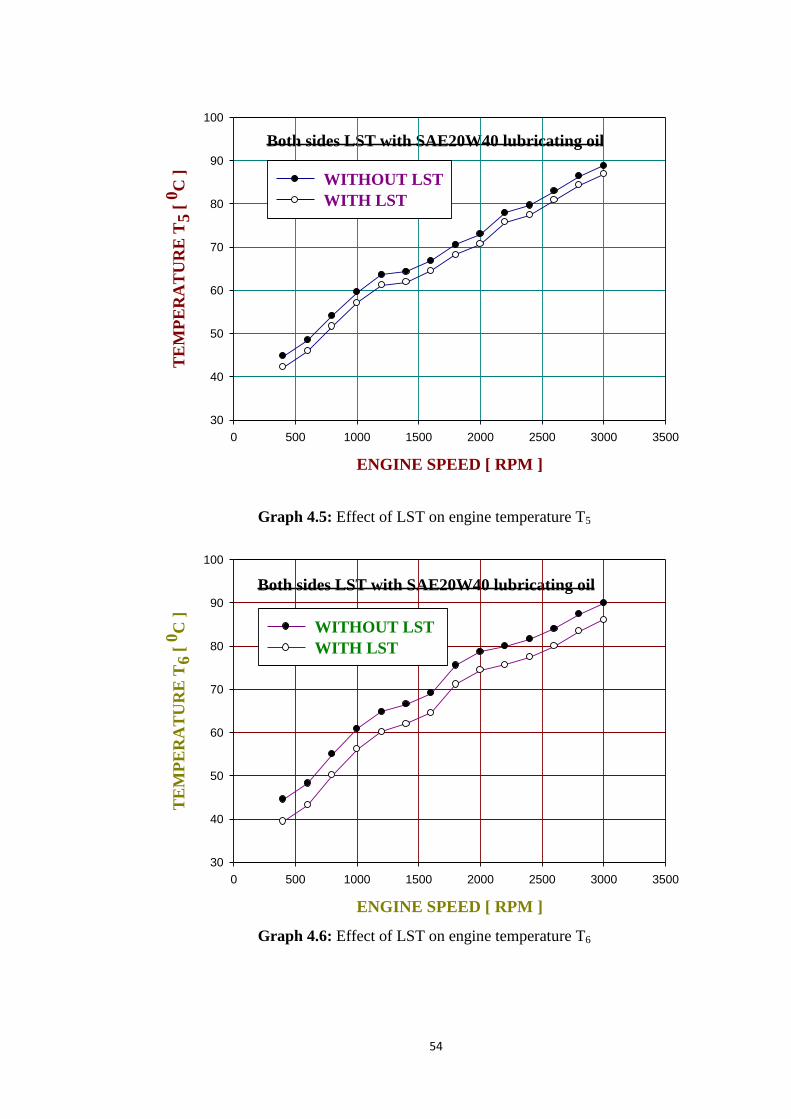
54
Both sides LST with SAE20W40 lubricating oil
ENGINE SPEED [ RPM ]
0 500 1000 1500 2000 2500 3000 3500
TE
MP
ER
AT
UR
E T
5 [
0C
]
30
40
50
60
70
80
90
100
WITHOUT LST
WITH LST
Graph 4.5: Effect of LST on engine temperature T5
Both sides LST with SAE20W40 lubricating oil
ENGINE SPEED [ RPM ]
0 500 1000 1500 2000 2500 3000 3500
TE
MP
ER
AT
UR
E T
6 [
0C
]
30
40
50
60
70
80
90
100
WITHOUT LST
WITH LST
Graph 4.6: Effect of LST on engine temperature T6

55
It is clearly shown in the graphs that the maximum temperature observed at 3000 rpm
(high speed) and minimum temperature observed at 400 rpm (low speed) in normal piston
rings as well as both sides laser surface texture piston rings at different six locations.
The results of these above graphs are analyzed and concluded that the effect of laser
surface texture from 400 engine rpm to 3000 engine rpm in the increment of 200 engine
rpm on TDC and BDC temperature for all cylinder show that temperature increases with
speed linearly.
It is seen that the top dead center temperature (T1) of cylinder-1 increments from 42.0°C
to 66.6°C as the speed of the engine increments from 400 rpm to 3000 rpm without LST
and in thus the relating regards for both side LST are 38.2°C and 64.8°C.
The bottom dead center temperature (T2) of cylinder-1 is marked to increases from
45.5°C to 87.0°C once engine speed rises from 400 rpm to 3000 rpm without LST and in
this manner, the relating regards for both side LST are 39.7°C and 83.0°C.
This is noticed that the cylinder-2 top dead center temperature (T3) increases from
46.1°C to 87.2°C as the speed of the engine up from 400 rpm to 3000 rpm without LST
and the relating esteem are 40.1°C and 82.7°C for both side LST.
This is shown that the cylinder-2 bottom dead center temperature (T4) rises from
47.0°C to 96.5°C, as the speed of the engine increases from 400 rpm to 3000 rpm without
LST and relating esteems are 41.1°C and 92.2°C for both sides LST.
The top dead center temperature (T5) of the cylinder-3 is recorded to rise from 44.8°C
to 88.8°C as the speed of the engine improves from 400 rpm to 3000 rpm without LST and
the comparing esteems for both side LST are 42.2°C and 86.8°C.
The bottom dead center temperature (T6) of the cylinder-3 is observed to increases from
44.5°C to 89.9°C as the speed of the engine accelerates from 400 rpm to 3000 rpm without
LST and the comparing esteems for both side LST are 39.4°C and 86.1°C.
4.2.2 Effect of both sides LST on lubricating oil temperature using SAE20W40
lubricating oil.
The graph 4.7 is indicated the effect of both sides portion laser surface textures of the
piston rings on the lubricating oil temperature T7 (0C) by comparing engine speed (rpm)
and lubricating oil temperature T7 (0C) with using SAE20W40 lubricating oil for the
without LST (black circle line) and with LST piston ring (white circle line).

56
Both sides LST with SAE20W40 lubricating oil
ENGINE SPEED [ RPM ]
0 500 1000 1500 2000 2500 3000 3500
LU
BR
ICA
TIN
G O
IL T
EM
P.
T7
[ 0
C ]
30
40
50
60
70
80
90
100
110
WITHOUT LST
WITH LST
Graph 4.7: Effect of LST on lubricating oil temperature (T7)
The temperature of lubricating oil has been found to rise from 48.80C to 98.2
0C as the
speed of the engine rises from 400 engine rpm to 3000 engine rpm with no LST and the
relating esteems are 34.70C and 86.2
0C for both side laser surface texture.
It is likewise seen that for both side laser surface texture with a specific speed of the
engine of 400 engine revolution and 3000 engine rpm, lubricating oil temperature has
reported 28.89 % and 12.22 % respectively lower in comparison with without laser surface
texture. It tends to be reasoned that LST assists in diminishing the lubricating oil
temperature.
4.2.3 Effect of both sides LST on bearing temperature with using SAE20W40
lubricating oil
The below graph 4.8 depicts the effect of both sides portion laser surface textures of the
piston rings on the bearing temperature by comparing the relationship between engine
speed and inner side bearing temperature (T8) and graph 4.9 depicts the relationship
between engine speed and outer side bearing temperature (T9) with using SAE20W40
lubricating oil.
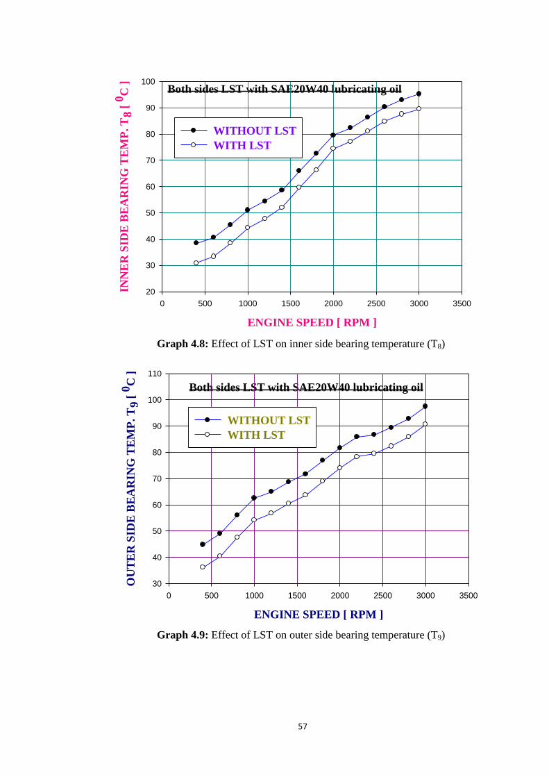
57
Both sides LST with SAE20W40 lubricating oil
ENGINE SPEED [ RPM ]
0 500 1000 1500 2000 2500 3000 3500
INN
ER
SID
E B
EA
RIN
G T
EM
P.
T8
[ 0
C ]
20
30
40
50
60
70
80
90
100
WITHOUT LST
WITH LST
Graph 4.8: Effect of LST on inner side bearing temperature (T8)
Both sides LST with SAE20W40 lubricating oil
ENGINE SPEED [ RPM ]
0 500 1000 1500 2000 2500 3000 3500
OU
TE
R S
IDE
BE
AR
ING
TE
MP
. T
9 [
0C
]
30
40
50
60
70
80
90
100
110
WITHOUT LST
WITH LST
Graph 4.9: Effect of LST on outer side bearing temperature (T9)

58
When the engine speed rises, both bearing temperature likewise rises straightly.
It is additionally analyzed that the inner side bearing temperature rises from 38.4°C to
95.2°C as the speed of the engine rises from 400 rpm to 3000 rpm with no LST and the
relating esteems are 30.9°C and 89.5°C with LST.
The temperature of the outer side bearing rises from 44.8°C to 97.4°C as the speed of
the engine rises between 400 rpm and 3000 rpm with no LST and the comparing esteems
are 36.1°C and 90.6°C with LST.
In both cases, it has been found if the average inner and outer side bearing temperature
is decreased by using both sides portion LST piston rings. Because of the decrease in the
temperature of the inner and outside side bearing, a frictional loss has also been reduced.
4.2.4 Effect of both sides LST on friction power with using SAE20W40 lubricating oil
The graph 4.10 is indicated the effect of both sides portion laser surface textures of the
piston rings on the friction power by the comparison of engine speed (rpm) and friction
power consumption (KW) with using SAE20W40 lubricating oil for without LST (black
circle line) and with LST piston ring (white circle line).
Both sides LST with SAE20W40 lubricating oil
ENGINE SPEED [ RPM ]
0 500 1000 1500 2000 2500 3000 3500FR
ICT
ION
PO
WE
R C
ON
SU
MP
TIO
N [
KW
]
0
1
2
3
4
5
WITHOUT LST
WITH LST
Graph 4.10: Effect of LST on frictional power consumption
Conclusion
The friction power consumption increases with engine speed linearly.

59
Minimum friction power consumption at 400 engine speed (low speed) and maximum
friction power consumption at 3000 engine speed (high speed) in the two cases.
It is also determined that the power consumption for friction, increments from 0.60KW
to 4.30KW as the speed of the engine increments from 400 revolutions of the engine to
3000 revolutions of the engine with no LST and the relating esteem of both side laser
surface textures are 0.58KW and 4.11KW.
The friction power consumption with a normal piston ring is greater compare to both
side laser surface texture piston ring at all observed engine speed.
The average percentage reduction in power consumption is 9.36% using both sides
Laser surface texturing piston rings with and SAE20W40 lubricating oil.
4.2.5 Effect of both sides LST on engine temperature with using SAE20W50
lubricating oil
In case-1 part-II, graphs 4.11 to 4.16 are represented the effect of both sides portion
laser surface textures of the piston rings on engine temperature with using SAE20W50
lubricating oil.
These graphs are indicated the comparison of engine speed (rpm) and temperature (0C)
at different six locations without LST (black circle line) and with LST piston ring (white
circle line).
Both sides LST with SAE20W50 lubricating oil
ENGINE SPEED [ RPM ]
0 500 1000 1500 2000 2500 3000 3500
TE
MP
ER
AT
UR
E T
1 [
OC
]
35
40
45
50
55
60
65
70
WITHOUT LST
WITH LST
Graph 4.11: Effect of LST on engine temperature T1

60
Both sides LST with SAE20W50 lubricating oil
ENGINE SPEED [ RPM ]
0 500 1000 1500 2000 2500 3000 3500
TE
MP
ER
AT
UR
E T
2 [
OC
]
30
40
50
60
70
80
90
WITHOUT LST
WITH LST
Graph 4.12: Effect of LST on engine temperature T2
Both sides LST with SAE20W50 lubricating oil
ENGINE SPEED [ RPM ]
0 500 1000 1500 2000 2500 3000 3500
TE
MP
ER
AT
UR
E T
3 [
OC
]
30
40
50
60
70
80
90
WITHOUT LST
WITH LST
Graph 4.13: Effect of LST on engine temperature T3

61
Both sides LST with SAE20W50 lubricating oil
ENGINE SPEED [ RPM ]
0 500 1000 1500 2000 2500 3000 3500
TE
MP
ER
AT
UR
E T
4 [
OC
]
30
40
50
60
70
80
90
100
WITHOUT LST
WITH LST
Graph 4.14: Effect of LST on engine temperature T4
Both sides LST with SAE20W50 lubricating oil
ENGINE SPEED [ RPM ]
0 500 1000 1500 2000 2500 3000 3500
TE
MP
ER
AT
UR
E T
5 [
OC
]
30
40
50
60
70
80
90
100
WITHOUT LST
WITH LST
Graph 4.15: Effect of LST on engine temperature T5

62
Both sides LST with SAE20W50 lubricating oil
ENGINE SPEED [ RPM ]
0 500 1000 1500 2000 2500 3000 3500
TE
MP
ER
AT
UR
E T
6 [
OC
]
30
40
50
60
70
80
90
100
WITHOUT LST
WITH LST
Graph 4.16: Effect of LST on engine temperature T6
It is clearly shown in the graph that the maximum temperature observed at 3000 rpm
(high speed) and minimum temperature observed at 400 rpm (low speed) in normal piston
rings as well as both side laser surface texture piston rings at different six locations.
The results of these above graphs are analyzed and concluded that the effect of laser
surface texture from 400 engine rpm to 3000 engine rpm in the increment of 200 engine
rpm on TDC and BDC temperature for all cylinder show that temperature increases with
speed linearly.
It is seen that the top dead center temperature (T1) of cylinder-1 increments from 42.0°C
to 66.6°C as the speed of the engine increments from 400 rpm to 3000 rpm without LST
and in thus the relating regards for both side LST are 37.0°C and 63.0°C.
The bottom dead center temperature (T2) of cylinder-1 is marked to increases from
45.5°C to 87.0°C once engine speed rises from 400 rpm to 3000 rpm without LST and in
this manner, the relating regards for both side LST are 38.6°C and 83.1°C.
This is noticed that the cylinder-2 top dead center temperature (T3) increases from
46.1°C to 87.2°C as the speed of the engine up from 400 rpm to 3000 rpm without LST
and the relating esteem are 38.0°C and 81.3°C for both side LST.

63
This is shown that the cylinder-2 bottom dead center temperature (T4) rises from
47.0°C to 96.5°C, as the speed of the engine increases from 400 rpm to 3000 rpm without
LST and relating esteems are 40.4°C and 91.5°C for both sides LST.
The top dead center temperature (T5) of the cylinder-3 is recorded to rise from 44.8°C
to 88.8°C as the speed of the engine improves from 400 rpm to 3000 rpm without LST and
the comparing esteems for both side LST are 38.7°C and 84.3°C.
The bottom dead center temperature (T6) of the cylinder-3 is observed to increases from
44.5°C to 89.9°C as the speed of the engine accelerates from 400 rpm to 3000 rpm without
LST and the comparing esteems for both side LST are 39.8°C and 86.3°C.
4.2.6 Effect of both sides LST on lubricating oil temperature with using SAE20W50
lubricating oil
The graph 4.17 is indicated the effect of both sides portion laser surface textures of the
piston rings on the lubricating oil temperature by the comparison of engine speed (rpm)
and lubricating oil temperature T7 (0C) with using SAE20W50 lubricating oil for without
LST (black circle line) and with LST piston ring (white circle line).
Both sides LST with SAE20W50 lubricating oil
ENGINE SPEED [ RPM ]
0 500 1000 1500 2000 2500 3000 3500
LU
BR
ICA
TIN
G O
IL T
EM
P. T
7 [
OC
]
30
40
50
60
70
80
90
100
110
WITHOUT LST
WITH LST
Graph 4.17: Effect of LST on lubricating oil temperature (T7)
The temperature of lubricating oil has been found to rise from 48.80C to 98.2
0C as the
speed of the engine rises from 400 engine rpm to 3000 engine rpm with no LST and the
comparing esteems of both sides laser surface texture are 36.70C and 88.6
0C.

64
It is also seen that for both side laser surface textures with a specific speed of the engine
of 400 engine revolution and 3000 engine rpm, lubricating oil temperature has reported
24.79 % and 9.77 % respectively lower in comparison with without laser surface texture. It
tends to be presumed that LST assists with lessening the lubricating oil temperature.
4.2.7 Effect of both sides LST on bearing temperature with using SAE20W50
lubricating oil
The below graph 4.18 depicts the effect of both sides portion laser surface textures of
the piston rings on the bearing temperature by the relationship between engine speed and
inner side bearing temperature (T8) and graph 4.19 depicts the relationship between engine
speed and outer side bearing temperature (T9) with using SAE20W50 lubricating oil.
Both sides LST with SAE20W50 lubricating oil
ENGINE SPEED [ RPM ]
0 500 1000 1500 2000 2500 3000 3500
INN
ER
SID
E B
EA
RIN
G T
EM
P. T
8 [
OC
]
20
30
40
50
60
70
80
90
100
WITHOUT LST
WITH LST
Graph 4.18: Effect of LST on inner side bearing temperature (T8)

65
Both sides LST with SAE20W50 lubricating oil
ENGINE SPEED [ RPM ]
0 500 1000 1500 2000 2500 3000 3500
OU
TE
R S
IDE
BE
AR
ING
TE
MP
. T
9 [
OC
]
30
40
50
60
70
80
90
100
110
WITHOUT LST
WITH LST
Graph 4.19: Effect of LST on outer side bearing temperature (T9)
When the engine speed increases, both bearing temperatures also rise directly.
It is also found that the inner side bearing temperature rises from 38.4°C to 95.2°C as
the speed of the engine rises from 400 rpm to 3000 rpm with no LST and the comparing
esteems are 30.2°C and 89.3°C with LST.
The temperature of the outer side bearing is increased between 44.8°C and 97.4°C as
the speed of the engine increases between 400 rpm and 3000 rpm with no LST and the
relating esteems are 35.6°C and 90.7°C with LST.
In both cases, it has been found that by using LST piston rings, the average inner and
outer side bearing temperature of the bearing is reduced. Owing to the decrease in the
temperature of the inner and outer side bearing, a frictional loss has also been reduced.
4.2.8 Effect of both sides LST on friction power with using SAE20W50 lubricating oil
The graph 4.20 is indicated the effect of both sides portion LST of the piston rings on
the friction power by the comparison of engine speed (rpm) and friction power
consumption (KW) with using SAE20W50 for without LST (black circle line) and with
LST piston ring (white circle line).

66
Both sides LST with SAE20W50 lubricating oil
ENGINE SPEED [ RPM ]
0 500 1000 1500 2000 2500 3000 3500
FR
ICT
ION
PO
WE
R C
ON
SU
MP
TIO
N [
KW
]
0
1
2
3
4
5
WITHOUT LST
WITH LST
Graph 4.20: Effect of LST on frictional power consumption
Conclusion
The following major observations are derived from the plotted graph 4.20.
The friction power consumption increases with engine speed linearly. Minimum friction
power consumption at 400 engine speed (low speed) and maximum friction power
consumption at 3000 engine speed (high speed) in both cases.
It is also noted that the power consumption for friction, increments from 0.60KW to
4.30KW as the speed of the engine increments from 400 revolutions of the engine to 3000
revolutions of the engine with no LST and the relating esteem for both side laser surface
textures are 0.58KW and 4.10KW.
The friction power consumption with a normal piston ring is greater compare to both
side laser surface texture piston ring at all observed engine speed.
The average power consumption reduction is 10.71% on both sides of laser surface
textured piston rings and SAE20W50 lubricating oil.
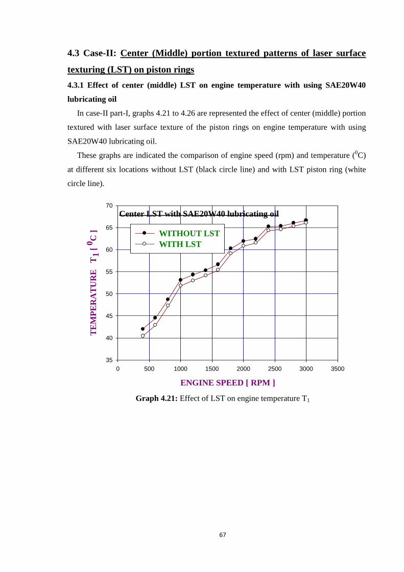
67
4.3 Case-II: Center (Middle) portion textured patterns of laser surface
texturing (LST) on piston rings
4.3.1 Effect of center (middle) LST on engine temperature with using SAE20W40
lubricating oil
In case-II part-I, graphs 4.21 to 4.26 are represented the effect of center (middle) portion
textured with laser surface texture of the piston rings on engine temperature with using
SAE20W40 lubricating oil.
These graphs are indicated the comparison of engine speed (rpm) and temperature (0C)
at different six locations without LST (black circle line) and with LST piston ring (white
circle line).
Center LST with SAE20W40 lubricating oil
ENGINE SPEED [ RPM ]
0 500 1000 1500 2000 2500 3000 3500
TE
MP
ER
AT
UR
E
T1
[ 0
C ]
35
40
45
50
55
60
65
70
WITHOUT LST
WITH LST
Graph 4.21: Effect of LST on engine temperature T1

68
Center LST with SAE20W40 lubricating oil
ENGINE SPEED [ RPM ]
0 500 1000 1500 2000 2500 3000 3500
TE
MP
ER
AT
UR
E
T2
[ 0
C ]
40
50
60
70
80
90
WITHOUT LST
WITH LST
Graph 4.22: Effect of LST on engine temperature T2
Center LST with SAE20W40 lubricating oil
ENGINE SPEED [ RPM ]
0 500 1000 1500 2000 2500 3000 3500
TE
MP
ER
AT
UR
E T
3 [
0C
]
40
50
60
70
80
90
WITHOUT LST
WITH LST
Graph 4.23: Effect of LST on engine temperature T3
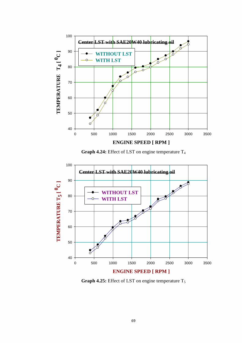
69
Center LST with SAE20W40 lubricating oil
ENGINE SPEED [ RPM ]
0 500 1000 1500 2000 2500 3000 3500
TE
MP
ER
AT
UR
E
T4
[ 0
C ]
40
50
60
70
80
90
100
WITHOUT LST
WITH LST
Graph 4.24: Effect of LST on engine temperature T4
Center LST with SAE20W40 lubricating oil
ENGINE SPEED [ RPM ]
0 500 1000 1500 2000 2500 3000 3500
TE
MP
ER
AT
UR
E T
5 [
0C
]
40
50
60
70
80
90
100
WITHOUT LST
WITH LST
Graph 4.25: Effect of LST on engine temperature T5
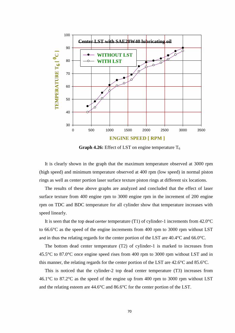
70
Center LST with SAE20W40 lubricating oil
ENGINE SPEED [ RPM ]
0 500 1000 1500 2000 2500 3000 3500
TE
MP
ER
AT
UR
E T
6 [
0C
]
30
40
50
60
70
80
90
100
WITHOUT LST
WITH LST
Graph 4.26: Effect of LST on engine temperature T6
It is clearly shown in the graph that the maximum temperature observed at 3000 rpm
(high speed) and minimum temperature observed at 400 rpm (low speed) in normal piston
rings as well as center portion laser surface texture piston rings at different six locations.
The results of these above graphs are analyzed and concluded that the effect of laser
surface texture from 400 engine rpm to 3000 engine rpm in the increment of 200 engine
rpm on TDC and BDC temperature for all cylinder show that temperature increases with
speed linearly.
It is seen that the top dead center temperature (T1) of cylinder-1 increments from 42.0°C
to 66.6°C as the speed of the engine increments from 400 rpm to 3000 rpm without LST
and in thus the relating regards for the center portion of the LST are 40.4°C and 66.0°C.
The bottom dead center temperature (T2) of cylinder-1 is marked to increases from
45.5°C to 87.0°C once engine speed rises from 400 rpm to 3000 rpm without LST and in
this manner, the relating regards for the center portion of the LST are 42.6°C and 85.6°C.
This is noticed that the cylinder-2 top dead center temperature (T3) increases from
46.1°C to 87.2°C as the speed of the engine up from 400 rpm to 3000 rpm without LST
and the relating esteem are 44.6°C and 86.6°C for the center portion of the LST.

71
This is shown that the cylinder-2 bottom dead center temperature (T4) rises from
47.0°C to 96.5°C, as the speed of the engine increases from 400 rpm to 3000 rpm without
LST and relating esteems are 43.1°C and 94.6°C for the center portion of the LST.
The top dead center temperature (T5) of the cylinder-3 is recorded to rise from 44.8°C
to 88.8°C as the speed of the engine improves from 400 rpm to 3000 rpm without LST and
the comparing esteems for the center portion of the LST are 43.0°C and 87.7°C.
The bottom dead center temperature (T6) of the cylinder-3 is observed to increases from
44.5°C to 89.9°C as the speed of the engine accelerates from 400 rpm to 3000 rpm without
LST and the comparing esteems for the center portion of the LST are 40.0°C and 87.6°C.
4.3.2 Effect of center (middle) LST on lubricating oil temperature using SAE20W40
lubricating oil
The graph 4.27 is indicated the effect of center (middle) portion textured with laser
surface texture of the piston rings on lubricating oil temperature by the comparison of
engine speed (rpm) and lubricating oil temperature T7 (0C) with using SAE20W40
lubricating oil for without LST (black circle line) and with LST piston ring (white circle
line).
Center LST with SAE20W40 lubricating oil
ENGINE SPEED [ RPM ]
0 500 1000 1500 2000 2500 3000 3500
LU
BR
ICA
TIN
G O
IL T
EM
P.
T7
[ 0
C ]
30
40
50
60
70
80
90
100
110
WITHOUT LST
WITH LST
Graph 4.27: Effect of LST on lubricating oil temperature (T7)

72
The temperature of lubricating oil has been found to rise from 48.80C to 98.2
0C as the
speed of the engine rises from 400 engine rpm to 3000 engine rpm with no LST and the
relating esteems are 39.50C and 91.6
0C for the center (middle) portion texture with laser
surface texture. It is also seen that for the center (middle) portion texture with laser surface
texture at a specific engine speed of 400 engine rpm and 3000 engine rpm, lubricating oil
temperature has reported 28.89% and 12.22 % respectively lower in comparison with
without laser surface texture. It is often inferred that LST assists to lessen the lubricating
oil temperature.
4.3.3 Effect of center (middle) LST on bearing temperature using SAE20W40
lubricating oil
The below graph 4.28 depicts the effect of center (middle) portion textured with laser
surface texture of the piston rings on the bearing temperature by the relationship between
engine speed and inner side bearing temperature (T8) and graph 4.29 depicts the
relationship between engine speed and outer side bearing temperature (T9) with using
SAE20W40 lubricating oil.
These graphs are indicated the comparison of engine speed (rpm) and temperature (0C)
at different six locations without LST (black circle line) and with LST piston ring (white
circle line).
Center LST with SAE20W40 lubricating oil
ENGINE SPEED [ RPM ]
0 500 1000 1500 2000 2500 3000 3500
INN
ER
SID
E B
EA
RIN
G T
EM
P.
T8
[ 0
C ]
20
30
40
50
60
70
80
90
100
WITHOUT LST
WITH LST
Graph 4.28: Effect of LST on inner side bearing temperature (T8)

73
Center LST with SAE20W40 lubricating oil
ENGINE SPEED [ RPM ]
0 500 1000 1500 2000 2500 3000 3500
OU
TE
R S
IDE
BE
AR
ING
TE
MP
. T
9 [
0C
]
30
40
50
60
70
80
90
100
110
WITHOUT LST
WITH LST
Graph 4.29: Effect of LST on outer side bearing temperature (T9)
When the engine speed increases, both bearing temperatures also rise directly.
It is also found that the inner side bearing temperature rises from 38.4°C to 95.2°C as
the speed of the engine rises from 400 rpm to 3000 rpm with no LST and the relating
esteems values are 32.6°C and 91.6°C with LST.
The temperature of the outer side bearing rises between 44.8°C and 97.4°C as the speed
of the engine rises between 400 rpm and 3000 rpm with no LST and the relating esteems
are 38.5°C and 93.6°C with LST.
In both cases, it has been found if the average inner and outer side bearing temperature
of the bearing is decreased by using LST piston rings. Owing to the decrease in the
temperature of the inner and outer side bearing, a frictional has loss also been reduced.
4.3.4 Effect of center (middle) LST on friction power with using SAE20W40
lubricating oil
The graph 4.30 is indicated the effect of center (middle) portion textured with laser
surface texture of the piston rings on the friction power by the comparison of engine speed
(rpm) and friction power consumption (KW) with using SAE20W40 for without LST
(black circle line) and with LST piston ring (white circle line).

74
Center LST with SAE20W40 lubricating oil
ENGINE SPEED [ RPM ]
0 500 1000 1500 2000 2500 3000 3500FR
ICT
ION
PO
WE
R C
ON
SU
MP
TIO
N [
KW
]
0
1
2
3
4
5
WITHOUT LST
WITH LST
Graph 4.30: Effect of LST on frictional power consumption
Conclusion
The following major observations are derived from the plotted graph 4.30.
The friction power consumption increases with engine speed linearly. Minimum friction
power consumption at 400 engine speed (low speed) and maximum friction power
consumption at 3000 engine speed (high speed) in both cases.
It is also noted that the power consumption for friction, increments from 0.60KW to
4.30KW as the speed of the engine increments from 400 revolutions of the engine to 3000
revolutions of the engine with no LST and the relating esteem of center portion laser
surface textures are 0.50KW and 4.10KW.
The friction power consumption with a normal piston ring is greater compare to center
(middle) portion texture with laser surface texture piston ring at all observed engine speed.
The average percentage reduction in power consumption is 15.43% using center
(middle) portion laser surface texturing piston rings with and SAE20W40 lubricating oil.
4.3.5 Effect of center (middle) LST on engine temperature with using SAE20W50
lubricating oil
In case-II part-II, graphs 4.31 to 4.36 are represented the effect of center (middle)
portion textured with laser surface texture on engine temperature with using SAE20W50
lubricating oil.
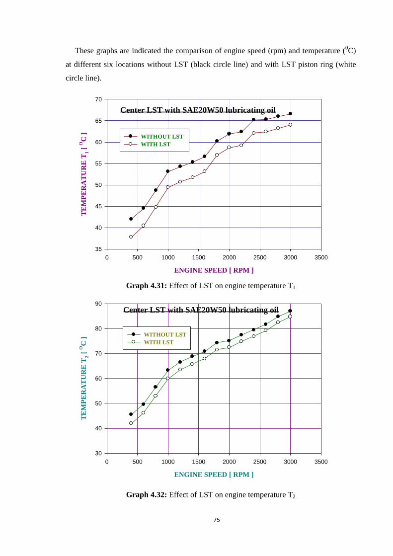
75
These graphs are indicated the comparison of engine speed (rpm) and temperature (0C)
at different six locations without LST (black circle line) and with LST piston ring (white
circle line).
Center LST with SAE20W50 lubricating oil
ENGINE SPEED [ RPM ]
0 500 1000 1500 2000 2500 3000 3500
TE
MP
ER
AT
UR
E T
1 [
OC
]
35
40
45
50
55
60
65
70
WITHOUT LST
WITH LST
Graph 4.31: Effect of LST on engine temperature T1
Center LST with SAE20W50 lubricating oil
ENGINE SPEED [ RPM ]
0 500 1000 1500 2000 2500 3000 3500
TE
MP
ER
AT
UR
E T
2 [
OC
]
30
40
50
60
70
80
90
WITHOUT LST
WITH LST
Graph 4.32: Effect of LST on engine temperature T2

76
Center LST with SAE20W50 lubricating oil
ENGINE SPEED [ RPM ]
0 500 1000 1500 2000 2500 3000 3500
TE
MP
ER
AT
UR
E T
3 [
OC
]
30
40
50
60
70
80
90
WITHOUT LST
WITH LST
Graph 4.33: Effect of LST on engine temperature T3
Center LST with SAE20W50 lubricating oil
ENGINE SPEED [ RPM ]
0 500 1000 1500 2000 2500 3000 3500
TE
MP
ER
AT
UR
E T
4 [
OC
]
30
40
50
60
70
80
90
100
WITHOUT LST
WITH LST
Graph 4.34: Effect of LST on engine temperature T4
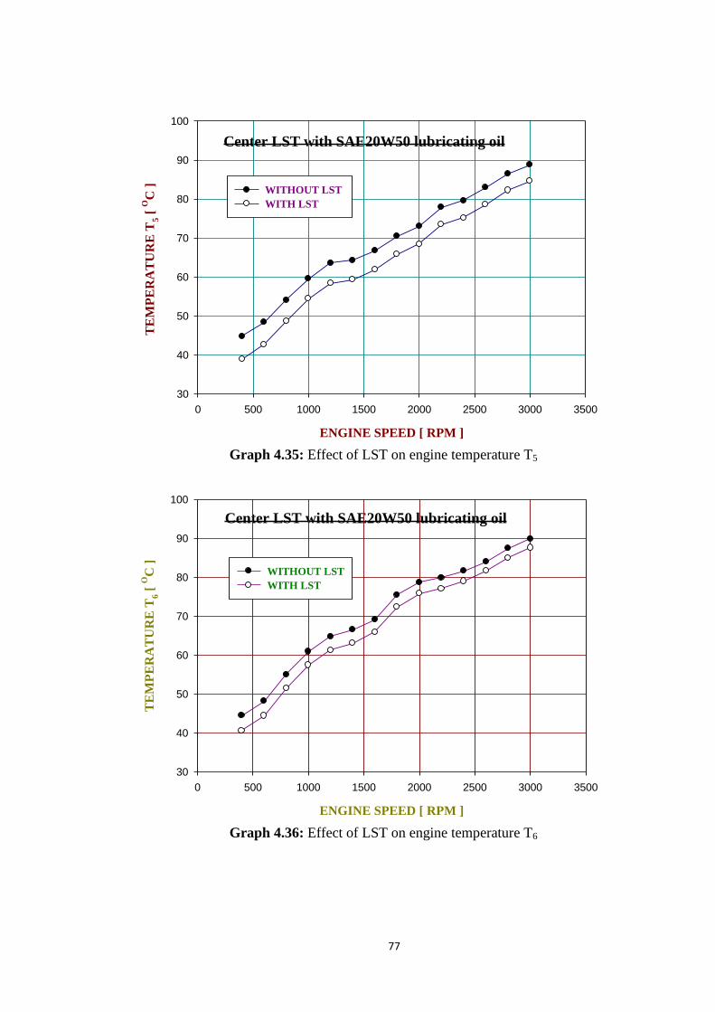
77
Center LST with SAE20W50 lubricating oil
ENGINE SPEED [ RPM ]
0 500 1000 1500 2000 2500 3000 3500
TE
MP
ER
AT
UR
E T
5 [
OC
]
30
40
50
60
70
80
90
100
WITHOUT LST
WITH LST
Graph 4.35: Effect of LST on engine temperature T5
Center LST with SAE20W50 lubricating oil
ENGINE SPEED [ RPM ]
0 500 1000 1500 2000 2500 3000 3500
TE
MP
ER
AT
UR
E T
6 [
OC
]
30
40
50
60
70
80
90
100
WITHOUT LST
WITH LST
Graph 4.36: Effect of LST on engine temperature T6
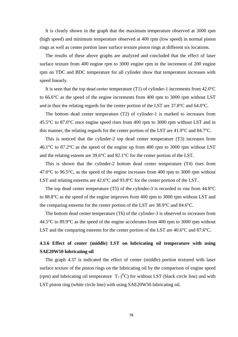
78
It is clearly shown in the graph that the maximum temperature observed at 3000 rpm
(high speed) and minimum temperature observed at 400 rpm (low speed) in normal piston
rings as well as center portion laser surface texture piston rings at different six locations.
The results of these above graphs are analyzed and concluded that the effect of laser
surface texture from 400 engine rpm to 3000 engine rpm in the increment of 200 engine
rpm on TDC and BDC temperature for all cylinder show that temperature increases with
speed linearly.
It is seen that the top dead center temperature (T1) of cylinder-1 increments from 42.0°C
to 66.6°C as the speed of the engine increments from 400 rpm to 3000 rpm without LST
and in thus the relating regards for the center portion of the LST are 37.8°C and 64.0°C.
The bottom dead center temperature (T2) of cylinder-1 is marked to increases from
45.5°C to 87.0°C once engine speed rises from 400 rpm to 3000 rpm without LST and in
this manner, the relating regards for the center portion of the LST are 41.9°C and 84.7°C.
This is noticed that the cylinder-2 top dead center temperature (T3) increases from
46.1°C to 87.2°C as the speed of the engine up from 400 rpm to 3000 rpm without LST
and the relating esteem are 39.6°C and 82.1°C for the center portion of the LST.
This is shown that the cylinder-2 bottom dead center temperature (T4) rises from
47.0°C to 96.5°C, as the speed of the engine increases from 400 rpm to 3000 rpm without
LST and relating esteems are 42.6°C and 93.8°C for the center portion of the LST.
The top dead center temperature (T5) of the cylinder-3 is recorded to rise from 44.8°C
to 88.8°C as the speed of the engine improves from 400 rpm to 3000 rpm without LST and
the comparing esteems for the center portion of the LST are 38.9°C and 84.6°C.
The bottom dead center temperature (T6) of the cylinder-3 is observed to increases from
44.5°C to 89.9°C as the speed of the engine accelerates from 400 rpm to 3000 rpm without
LST and the comparing esteems for the center portion of the LST are 40.6°C and 87.6°C.
4.3.6 Effect of center (middle) LST on lubricating oil temperature with using
SAE20W50 lubricating oil
The graph 4.37 is indicated the effect of center (middle) portion textured with laser
surface texture of the piston rings on the lubricating oil by the comparison of engine speed
(rpm) and lubricating oil temperature T7 (0C) for without LST (black circle line) and with
LST piston ring (white circle line) with using SAE20W50 lubricating oil.

79
Center LST with SAE20W50 lubricating oil
ENGINE SPEED [ RPM ]
0 500 1000 1500 2000 2500 3000 3500
LU
BR
ICA
TIN
G O
IL T
EM
P. T
7 [
OC
]
30
40
50
60
70
80
90
100
110
WITHOUT LST
WITH LST
Graph 4.37: Effect of LST on lubricating oil temperature (T7)
The temperature of the lubricating oil has been found to rise from 48.80C to 98.2
0C as
the speed of the engine rises from 400 engine rpm to 3000 engine rpm with no LST and the
relating esteems are 38.30C and 90.8
0C for the center (middle) portion texture of the laser
surface texture. It is also seen that for the center (middle) portion texture with laser surface
texture at a specific engine speed of 400 engine rpm and 3000 engine rpm, lubricating oil
temperature has reported 21.52% and 07.54 % respectively lower in comparison with
without laser surface texture. It is often inferred that LST assists to lessen the temperature
of the lubricating oil.
4.3.7 Effect of center (middle) LST on bearing temperature using SAE20W50
lubricating oil
The below graph 4.38 depicts the effect of center (middle) portion textured with laser
surface texture of the piston rings on bearing temperature by the relationship between
engine speed and inner side bearing temperature (T8) and graph 4.39 depicts the
relationship between engine speed and outer side bearing temperature (T9) with using
SAE20W50 lubricating oil.
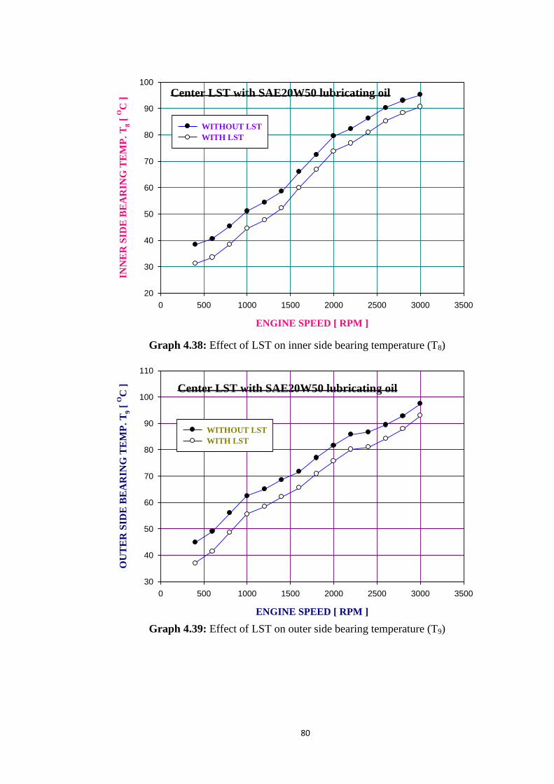
80
Center LST with SAE20W50 lubricating oil
ENGINE SPEED [ RPM ]
0 500 1000 1500 2000 2500 3000 3500
INN
ER
SID
E B
EA
RIN
G T
EM
P. T
8 [
OC
]
20
30
40
50
60
70
80
90
100
WITHOUT LST
WITH LST
Graph 4.38: Effect of LST on inner side bearing temperature (T8)
Center LST with SAE20W50 lubricating oil
ENGINE SPEED [ RPM ]
0 500 1000 1500 2000 2500 3000 3500
OU
TE
R S
IDE
BE
AR
ING
TE
MP
. T
9 [
OC
]
30
40
50
60
70
80
90
100
110
WITHOUT LST
WITH LST
Graph 4.39: Effect of LST on outer side bearing temperature (T9)

81
When the engine speed rises, both bearing temperatures also rises straightly.
It is also found that the inner side bearing temperature rises from 38.4°C to 95.2°C as
the speed of the engine rises from 400 rpm to 3000 rpm with no LST and the relating
esteems are 31.2°C and 90.6°C with LST.
The temperature of the outer side bearing rises between 44.8°C and 97.4°C as the speed
of the engine rises between 400 rpm and 3000 rpm with no LST and the relating esteems
are 37.0°C and 92.9°C with LST.
In both cases, it has been found if the average inner and outer side bearing temperature
of the bearing is decreased by using center portion LST piston rings. Owing to the
reduction of the outside bearing temperature also reduces the frictional loss.
4.3.8 Effect of center (middle) LST on friction power with using SAE20W50
lubricating oil
The graph 4.40 is indicated the effect of center (middle) portion textured with laser
surface texture of the piston rings on by the comparison of engine speed (rpm) and friction
power consumption (KW) with using SAE20W50 for without LST (black circle line) and
with LST piston ring (white circle line).
Center LST with SAE20W50 lubricating oil
ENGINE SPEED [ RPM ]
0 500 1000 1500 2000 2500 3000 3500
FR
ICT
ION
PO
WE
R C
ON
SU
MP
TIO
N [
KW
]
0
1
2
3
4
5
WITHOUT LST
WITH LST
Graph 4.40: Effect of LST on frictional power consumption
82
Conclusion
The following major observations are derived from the plotted graph 4.40.
The friction power consumption increases with engine speed linearly. Minimum friction
power consumption at 400 engine speed (low speed) and maximum friction power
consumption at 3000 engine speed (high speed) in both cases.
It is also noted that the power consumption for friction, increments from 0.60KW to
4.30KW as the speed of the engine increments from 400 revolutions of the engine to 3000
revolutions of the engine with no LST and the associated esteem with center portion laser
surface textures are 0.48KW and 4.00KW.
The friction power consumption with a normal piston ring is greater compare to center
(middle) portion texture with laser surface texture piston ring at all observed engine speed.
The average percentage reduction in power consumption is 19.57% using center
(middle) portion Laser surface texturing piston rings with and SAE20W50 lubricating oil.

83
4.4 Case-III: Full-width textured patterns of laser surface texturing
(LST) on piston rings
4.4.1 Effect of full-width LST on engine temperature with using SAE20W40
lubricating oil
In case-III part-I, graphs 4.41 to 4.46 are represented the effect of full-width textured
with laser surface texture on engine temperature with using SAE20W40 lubricating oil.
These graphs are indicated the comparison of engine speed (rpm) and temperature (0C)
at different six locations without LST (black circle line) and with LST piston ring (white
circle line).
Full width LST with SAE20W40 lubricating oil
ENGINE SPEED [ RPM ]
0 500 1000 1500 2000 2500 3000 3500
TE
MP
ER
AT
UR
E
T1
[ 0
C ]
35
40
45
50
55
60
65
70
WITHOUT LST
WITH LST
Graph 4.41: Effect of LST on engine temperature T1
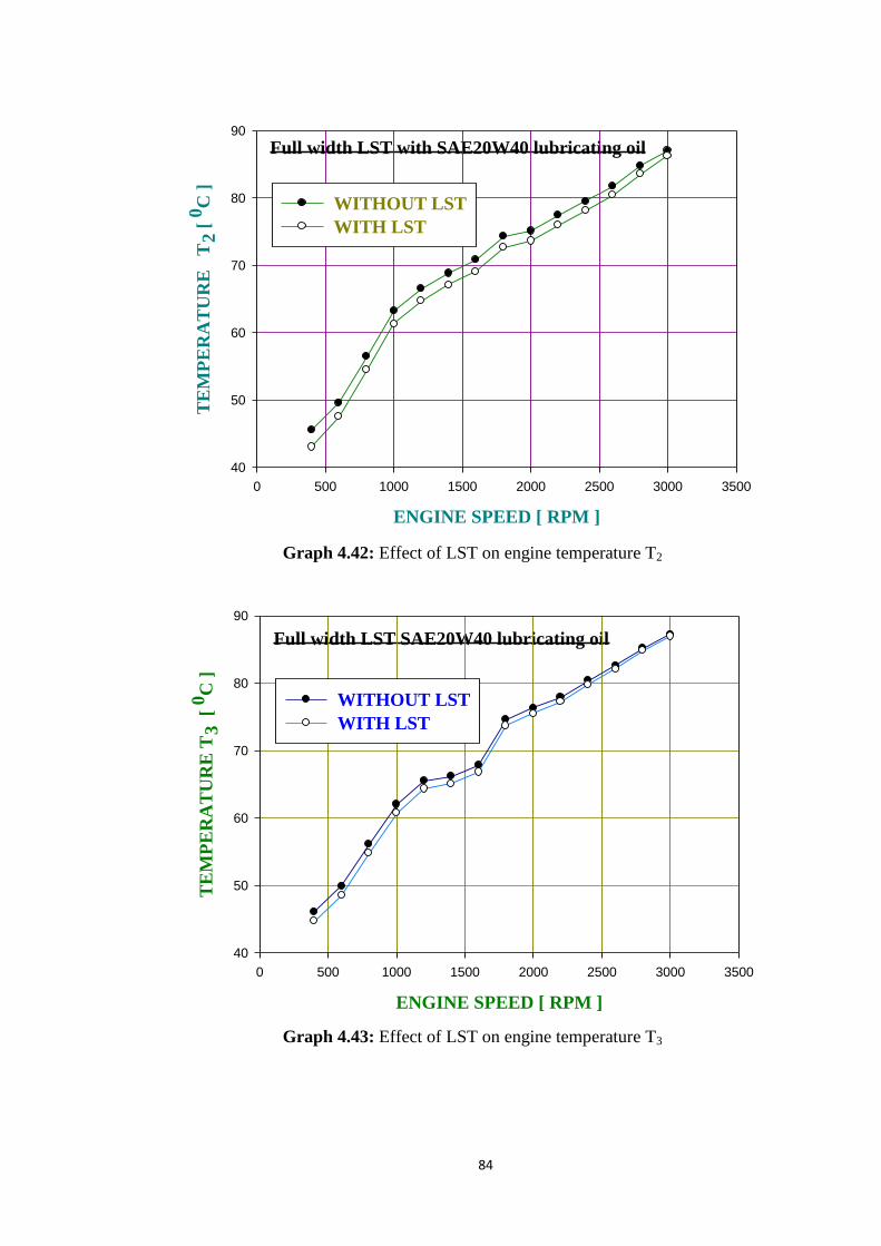
84
Full width LST with SAE20W40 lubricating oil
ENGINE SPEED [ RPM ]
0 500 1000 1500 2000 2500 3000 3500
TE
MP
ER
AT
UR
E
T2
[ 0
C ]
40
50
60
70
80
90
WITHOUT LST
WITH LST
Graph 4.42: Effect of LST on engine temperature T2
Full width LST SAE20W40 lubricating oil
ENGINE SPEED [ RPM ]
0 500 1000 1500 2000 2500 3000 3500
TE
MP
ER
AT
UR
E T
3
[ 0
C ]
40
50
60
70
80
90
WITHOUT LST
WITH LST
Graph 4.43: Effect of LST on engine temperature T3

85
Full width LST with SAE20W40 lubricating oil
ENGINE SPEED [ RPM ]
0 500 1000 1500 2000 2500 3000 3500
TE
MP
ER
AT
UR
E
T4
[ 0
C ]
40
50
60
70
80
90
100
WITHOUT LST
WITH LST
Graph 4.44: Effect of LST on engine temperature T4
Full width LST with SAE20W40 lubricating oil
ENGINE SPEED [ RPM ]
0 500 1000 1500 2000 2500 3000 3500
TE
MP
ER
AT
UR
E T
5 [
0C
]
40
50
60
70
80
90
100
WITHOUT LST
WITH LST
Graph 4.45: Effect of LST on engine temperature T5

86
Full width LST with SAE20W40 lubricating oil
ENGINE SPEED [ RPM ]
0 500 1000 1500 2000 2500 3000 3500
TE
MP
ER
AT
UR
E T
6 [
0C
]
30
40
50
60
70
80
90
100
WITHOUT LST
WITH LST
Graph 4.46: Effect of LST on engine temperature T6
It is clearly shown in the graph that the maximum temperature observed at 3000 rpm
(high speed) and minimum temperature observed at 400 rpm (low speed) in normal piston
rings as well as full-width laser surface texture piston rings at different six locations.
The results of these above graphs are analyzed and concluded that the effect of laser
surface texture from 400 engine rpm to 3000 engine rpm in the increment of 200 engine
rpm on TDC and BDC temperature for all cylinder show that temperature increases with
speed linearly.
It is seen that the top dead center temperature (T1) of cylinder-1 increments from 42.0°C
to 66.6°C as the speed of the engine increments from 400 rpm to 3000 rpm without LST
and in thus the relating regards for full-width LST are 40.6°C and 66.5°C.
The bottom dead center temperature (T2) of cylinder-1 is marked to increases from
45.5°C to 87.0°C once engine speed rises from 400 rpm to 3000 rpm without LST and in
this manner, the relating regards for full-width LST are 43.0°C and 86.3°C.
This is noticed that the cylinder-2 top dead center temperature (T3) increases from
46.1°C to 87.2°C as the speed of the engine up from 400 rpm to 3000 rpm without LST
and the relating esteem are 44.7°C and 86.9°C for full-width LST.
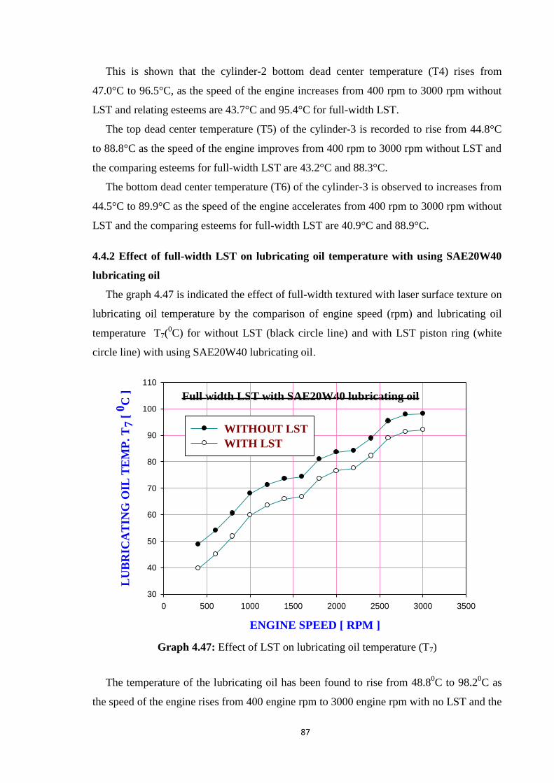
87
This is shown that the cylinder-2 bottom dead center temperature (T4) rises from
47.0°C to 96.5°C, as the speed of the engine increases from 400 rpm to 3000 rpm without
LST and relating esteems are 43.7°C and 95.4°C for full-width LST.
The top dead center temperature (T5) of the cylinder-3 is recorded to rise from 44.8°C
to 88.8°C as the speed of the engine improves from 400 rpm to 3000 rpm without LST and
the comparing esteems for full-width LST are 43.2°C and 88.3°C.
The bottom dead center temperature (T6) of the cylinder-3 is observed to increases from
44.5°C to 89.9°C as the speed of the engine accelerates from 400 rpm to 3000 rpm without
LST and the comparing esteems for full-width LST are 40.9°C and 88.9°C.
4.4.2 Effect of full-width LST on lubricating oil temperature with using SAE20W40
lubricating oil
The graph 4.47 is indicated the effect of full-width textured with laser surface texture on
lubricating oil temperature by the comparison of engine speed (rpm) and lubricating oil
temperature T7(0C) for without LST (black circle line) and with LST piston ring (white
circle line) with using SAE20W40 lubricating oil.
Full width LST with SAE20W40 lubricating oil
ENGINE SPEED [ RPM ]
0 500 1000 1500 2000 2500 3000 3500
LU
BR
ICA
TIN
G O
IL T
EM
P.
T7
[ 0
C ]
30
40
50
60
70
80
90
100
110
WITHOUT LST
WITH LST
Graph 4.47: Effect of LST on lubricating oil temperature (T7)
The temperature of the lubricating oil has been found to rise from 48.80C to 98.2
0C as
the speed of the engine rises from 400 engine rpm to 3000 engine rpm with no LST and the

88
relating esteems are 39.70C and 92.0
0C for full-width laser surface texture. It is also seen
that for full-width laser surface texture with a specific speed of the engine of 400 engine
revolution and 3000 engine rpm, lubricating oil temperature has reported 18.65% and
06.31% respectively lower in comparison with without laser surface texture. It is often
inferred that LST assists to lessen the temperature of the lubricating oil.
4.4.3 Effect of full-width LST on bearing temperature with using SAE20W40
lubricating oil
The below graph 4.48 depicts the effect of full-width textured with laser surface texture
on bearing temperature by the relationship between engine speed and inner side bearing
temperature (T8) and graph 4.49 depicts the relationship between engine speed and outer
side bearing temperature (T9) with using SAE20W40 lubricating oil.
Full width LST with SAE20W40 lubricating oil
ENGINE SPEED [ RPM ]
0 500 1000 1500 2000 2500 3000 3500
INN
ER
SID
E B
EA
RIN
G T
EM
P.
T8
[ 0
C ]
30
40
50
60
70
80
90
100
WITHOUT LST
WITH LST
Graph 4.48: Effect of LST on inner side bearing temperature (T8)

89
Full width LST with SAE20W40 lubricating oil
ENGINE SPEED [ RPM ]
0 500 1000 1500 2000 2500 3000 3500
OU
TE
R S
IDE
BE
AR
ING
TE
MP
. T
9 [
0C
]
30
40
50
60
70
80
90
100
110
WITHOUT LST
WITH LST
Graph 4.49: Effect of LST on outer side bearing temperature (T9)
When the engine speed rises, both bearing temperature also rises directly.
It is also found that the inner side bearing temperature rises from 38.4°C to 95.2°C as
the speed of the engine rises from 400 rpm to 3000 rpm with no LST and the relating
esteems are 34.2°C and 93.3°C with LST.
The temperature of the outer side bearing is increased between 44.8°C and 97.4°C as
the speed of the engine rises between 400 rpm to 3000 rpm with no LST and the relating
esteems are 40.2°C and 95.0°C with LST.
In both cases, it has been found if the overall bearing inner and outer side bearing
temperature is decreased by using full-width LST piston rings. Owing to the decrease in
the temperature of the inner and outer side bearing, a frictional loss has also been reduced.
4.4.4 Effect of full-width LST on friction power with using SAE20W40 lubricating oil
The graph 4.50 is indicated the effect of full-width textured with laser surface texture on
the friction power by the comparison of engine speed (rpm) and friction power
consumption (KW) with using SAE20W40 for without LST (black circle line) and with
LST piston ring (white circle line).

90
Full width LST with SAE20W40 lubricating oil
ENGINE SPEED [ RPM ]
0 500 1000 1500 2000 2500 3000 3500FR
ICT
ION
PO
WE
R C
ON
SU
MP
TIO
N [
KW
]
0
1
2
3
4
5
WITHOUT LST
WITH LST
Graph 4.50: Effect of LST on frictional power consumption
Conclusion
The following major observations are derived from the plotted graph 4.50.
The friction power consumption increases with engine speed linearly. Minimum friction
power consumption at 400 engine speed (low speed) and maximum friction power
consumption at 3000 engine speed (high speed) in both cases.
It is also noted that the power consumption for friction, increments from 0.60KW to
4.30KW as the speed of the engine increments from 400 revolutions of the engine to 3000
revolutions of the engine with no LST and the relating esteem with full-width laser surface
textures are 0.40KW and 4.00KW.
The friction power consumption with a normal piston ring is greater compare to the full-
width laser surface texture piston ring at all observed engine speed.
The average percentage reduction in power consumption is 26.07% using full-width laser
surface texturing piston rings with and SAE20W40 lubricating oil.

91
4.4.5 Effect of full-width LST on engine temperature with using SAE20W50
lubricating oil
In case-III part-II, graphs 4.51 to 4.56 are represented the effect of full-width textured
with laser surface texture on engine temperature with using SAE20W50 lubricating oil.
These graphs are indicated the comparison of engine speed (rpm) and temperature (0C)
at different six locations without LST (black circle line) and with LST piston ring (white
circle line).
Full width LST with SAE20W50 lubricating oil
ENGINE SPEED [ RPM ]
0 500 1000 1500 2000 2500 3000 3500
TE
MP
ER
AT
UR
E T
1 [
OC
]
35
40
45
50
55
60
65
70
WITHOUT LST
WITH LST
Graph 4.51: Effect of LST on engine temperature T1
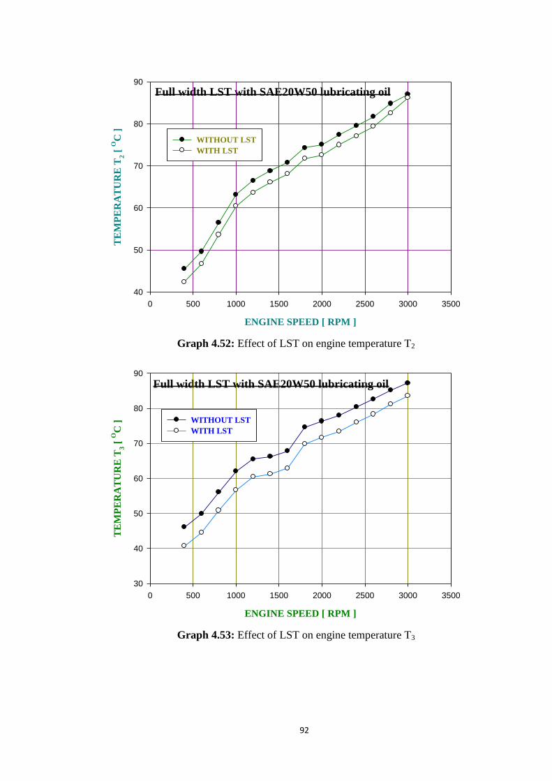
92
Full width LST with SAE20W50 lubricating oil
ENGINE SPEED [ RPM ]
0 500 1000 1500 2000 2500 3000 3500
TE
MP
ER
AT
UR
E T
2 [
OC
]
40
50
60
70
80
90
WITHOUT LST
WITH LST
Graph 4.52: Effect of LST on engine temperature T2
Full width LST with SAE20W50 lubricating oil
ENGINE SPEED [ RPM ]
0 500 1000 1500 2000 2500 3000 3500
TE
MP
ER
AT
UR
E T
3 [
OC
]
30
40
50
60
70
80
90
WITHOUT LST
WITH LST
Graph 4.53: Effect of LST on engine temperature T3
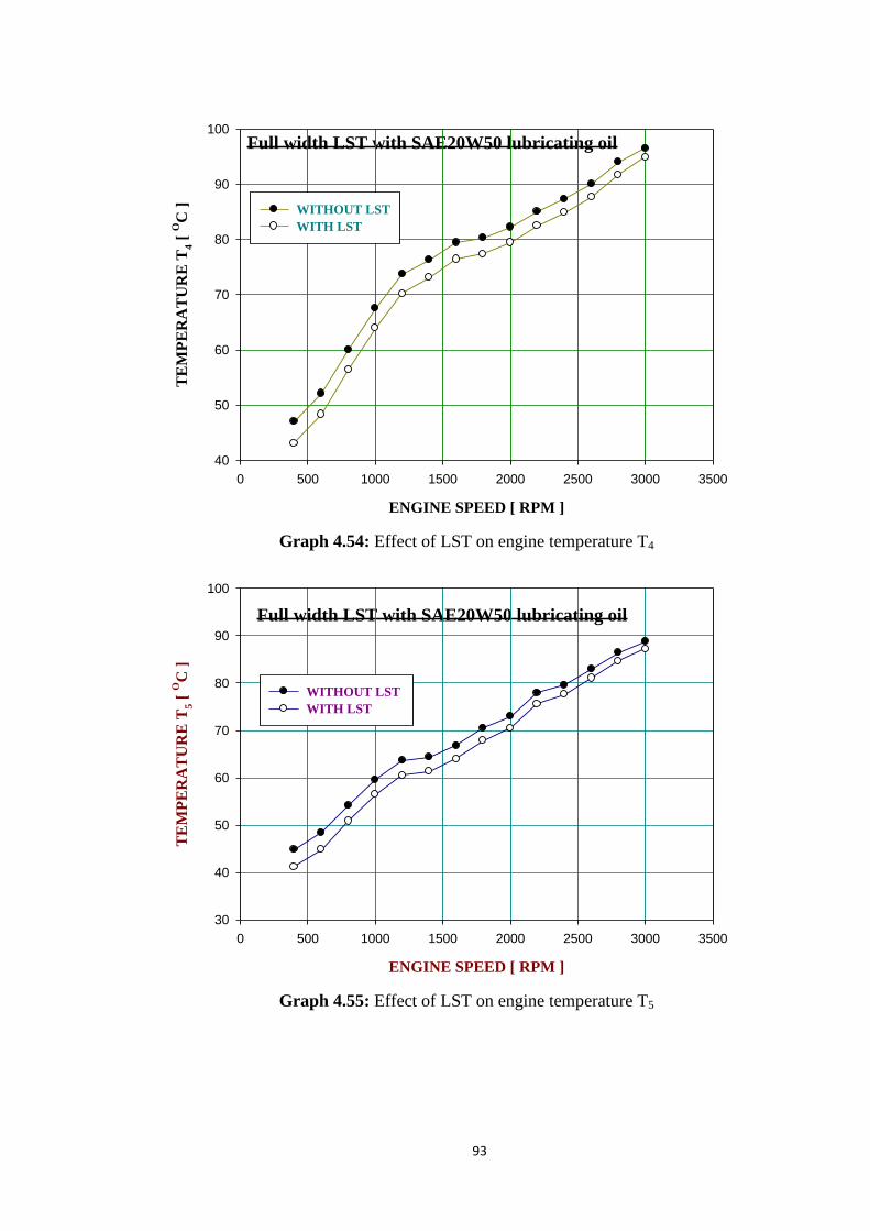
93
Full width LST with SAE20W50 lubricating oil
ENGINE SPEED [ RPM ]
0 500 1000 1500 2000 2500 3000 3500
TE
MP
ER
AT
UR
E T
4 [
OC
]
40
50
60
70
80
90
100
WITHOUT LST
WITH LST
Graph 4.54: Effect of LST on engine temperature T4
Full width LST with SAE20W50 lubricating oil
ENGINE SPEED [ RPM ]
0 500 1000 1500 2000 2500 3000 3500
TE
MP
ER
AT
UR
E T
5 [
OC
]
30
40
50
60
70
80
90
100
WITHOUT LST
WITH LST
Graph 4.55: Effect of LST on engine temperature T5

94
Full width LST with SAE20W50 lubricating oil
ENGINE SPEED [ RPM ]
0 500 1000 1500 2000 2500 3000 3500
TE
MP
ER
AT
UR
E T
6
[ O
C ]
30
40
50
60
70
80
90
100
WITHOUT LST
WITH LST
Graph 4.56: Effect of LST on engine temperature T6
It is clearly shown in the graph that the maximum temperature observed at 3000 rpm
(high speed) and minimum temperature observed at 400 rpm (low speed) in normal piston
rings as well as full-width laser surface texture piston rings at different six locations.
The results of these above graphs are analyzed and concluded that the effect of laser
surface texture from 400 engine rpm to 3000 engine rpm in the increment of 200 engine
rpm on TDC and BDC temperature for all cylinder show that temperature increases with
speed linearly.
It is seen that the top dead center temperature (T1) of cylinder-1 increments from 42.0°C
to 66.6°C as the speed of the engine increments from 400 rpm to 3000 rpm without LST
and in thus the relating regards for full-width LST are 38.1°C and 64.6°C.
The bottom dead center temperature (T2) of cylinder-1 is marked to increases from
45.5°C to 87.0°C once engine speed rises from 400 rpm to 3000 rpm without LST and in
this manner, the relating regards for full-width LST are 42.4°C and 86.2°C.
This is noticed that the cylinder-2 top dead center temperature (T3) increases from
46.1°C to 87.2°C as the speed of the engine up from 400 rpm to 3000 rpm without LST
and the relating esteem are 40.7°C and 83.5°C for full-width LST.
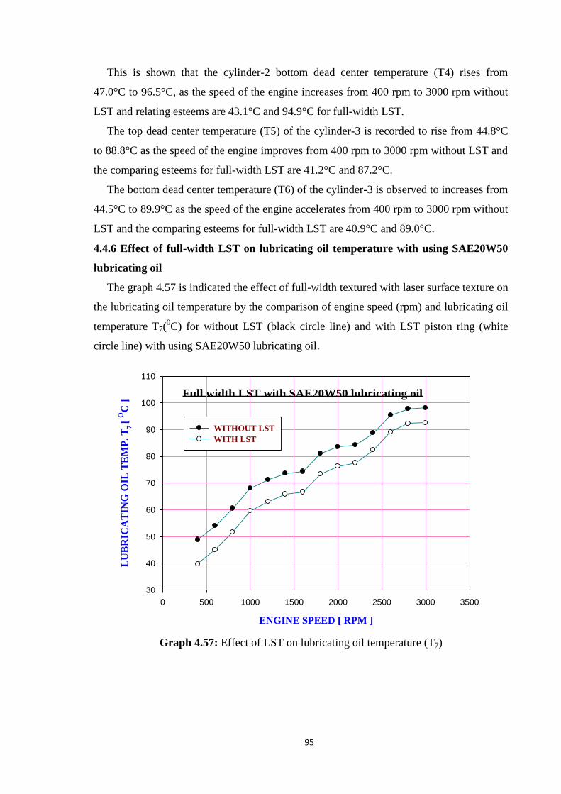
95
This is shown that the cylinder-2 bottom dead center temperature (T4) rises from
47.0°C to 96.5°C, as the speed of the engine increases from 400 rpm to 3000 rpm without
LST and relating esteems are 43.1°C and 94.9°C for full-width LST.
The top dead center temperature (T5) of the cylinder-3 is recorded to rise from 44.8°C
to 88.8°C as the speed of the engine improves from 400 rpm to 3000 rpm without LST and
the comparing esteems for full-width LST are 41.2°C and 87.2°C.
The bottom dead center temperature (T6) of the cylinder-3 is observed to increases from
44.5°C to 89.9°C as the speed of the engine accelerates from 400 rpm to 3000 rpm without
LST and the comparing esteems for full-width LST are 40.9°C and 89.0°C.
4.4.6 Effect of full-width LST on lubricating oil temperature with using SAE20W50
lubricating oil
The graph 4.57 is indicated the effect of full-width textured with laser surface texture on
the lubricating oil temperature by the comparison of engine speed (rpm) and lubricating oil
temperature T7(0C) for without LST (black circle line) and with LST piston ring (white
circle line) with using SAE20W50 lubricating oil.
Full width LST with SAE20W50 lubricating oil
ENGINE SPEED [ RPM ]
0 500 1000 1500 2000 2500 3000 3500
LU
BR
ICA
TIN
G O
IL T
EM
P. T
7 [
OC
]
30
40
50
60
70
80
90
100
110
WITHOUT LST
WITH LST
Graph 4.57: Effect of LST on lubricating oil temperature (T7)

96
The temperature of lubricating oil has been found to rise from 48.80C to 98.2
0C as the
speed of the engine rises from 400 engine rpm to 3000 engine rpm with no LST and the
relating esteems are 39.70C and 92.6
0C for full-width laser surface texture.
It is also seen that for full-width laser surface texture with a specific speed of the
engine of 400 engine revolution and 3000 engine rpm, lubricating oil temperature has
reported 18.65% and 05.70% respectively lower in comparison with without laser surface
texture. It tends to presumed that LST assists to lessen the temperature of the lubricating
oil.
4.4.7 Effect of full-width LST on bearing temperature with using SAE20W50
lubricating oil
The below graph 4.58 depicts the effect of full-width textured with laser surface texture
on bearing temperature by the relationship between engine speed and inner side bearing
temperature (T8) and graph 4.59 depicts the relationship between engine speed and outer
side bearing temperature (T9) with using SAE20W50 lubricating oil.
Full width LST with SAE20W50 lubricating oil
ENGINE SPEED [ RPM ]
0 500 1000 1500 2000 2500 3000 3500
INN
ER
SID
E B
EA
RIN
G T
EM
P. T
8 [
OC
]
20
30
40
50
60
70
80
90
100
WITHOUT LST
WITH LST
Graph 4.58: Effect of LST on inner side bearing temperature (T8)

97
Full width LST with SAE20W50 lubricating oil
ENGINE SPEED [ RPM ]
0 500 1000 1500 2000 2500 3000 3500
OU
TE
R S
IDE
BE
AR
ING
TE
MP
. T
9 [
OC
]
30
40
50
60
70
80
90
100
110
WITHOUT LST
WITH LST
Graph 4.59: Effect of LST on outer side bearing temperature (T9)
When the engine speed increases, both bearing temperature also rises directly.
It is also found that the inner side bearing temperature rises from 38.4°C to 95.2°C as
the speed of the engine rises from 400 rpm to 3000 rpm with no LST and the relating
esteems are 32.8°C and 92.8°C with LST.
The temperature of the outer side bearing is increased between 44.8°C and 97.4°C as
the speed of the engine increases between 400 rpm and 3000 rpm with no LST and the
relating esteems are 39.0°C and 94.8°C with LST.
In both cases, it has been found if the average inner side and outer side bearing
temperature is decreased by using full LST piston rings. Owing to the decrease in the
temperature of the inner and outer side bearing, a frictional loss has also been reduced.

98
4.4.8 Effect of full-width LST on friction power with using SAE20W50 lubricating oil
The graph 4.60 is indicated the effect of full-width textured with laser surface texture on
the friction power by the comparison of engine speed (rpm) and friction power
consumption (KW) with using SAE20W50 for without LST (black circle line) and with
LST piston ring (white circle line).
Full width LST with SAE20W50 lubricating oil
ENGINE SPEED [ RPM ]
0 500 1000 1500 2000 2500 3000 3500
FR
ICT
ION
PO
WE
R C
ON
SU
MP
TIO
N [
KW
]
0
1
2
3
4
5
WITHOUT LST
WITH LST
Graph 4.60: Effect of LST on frictional power consumption
Conclusion
The following major observations are derived from the plotted graph 4.60.
The friction power consumption increases with engine speed linearly. Minimum friction
power consumption at 400 engine speed (low speed) and maximum friction power
consumption at 3000 engine speed (high speed) in both cases.
It is also noted that the power consumption for friction, increments from 0.60KW to
4.30KW as the speed of the engine increments from 400 revolutions of the engine to 3000
revolutions of the engine with no LST and the relating esteem with full-width laser surface
textures are 0.40KW and 3.90KW.
The friction power consumption with a normal piston ring is greater compare to the full-
width laser surface texture piston ring at all observed engine speed.
The average percentage reduction in power consumption is 29.21% using full-width
Laser surface texturing piston rings with and SAE20W50 lubricating oil.
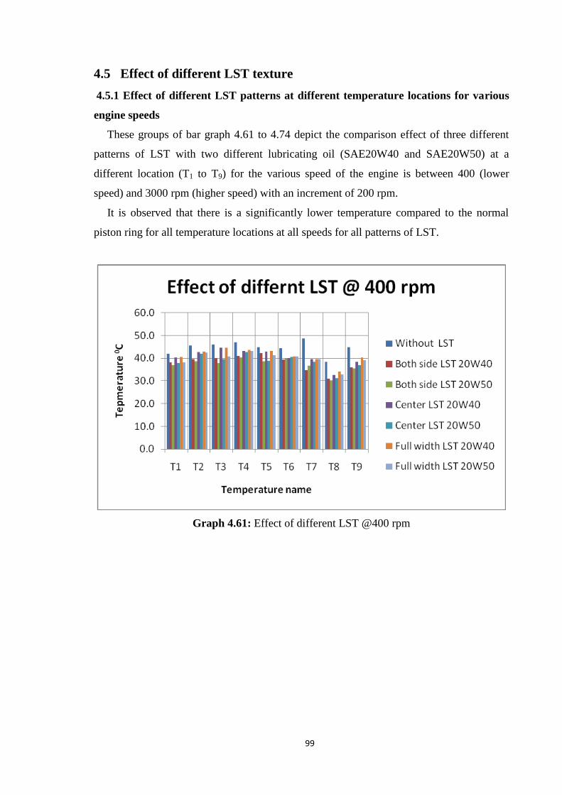
99
4.5 Effect of different LST texture
4.5.1 Effect of different LST patterns at different temperature locations for various
engine speeds
These groups of bar graph 4.61 to 4.74 depict the comparison effect of three different
patterns of LST with two different lubricating oil (SAE20W40 and SAE20W50) at a
different location (T1 to T9) for the various speed of the engine is between 400 (lower
speed) and 3000 rpm (higher speed) with an increment of 200 rpm.
It is observed that there is a significantly lower temperature compared to the normal
piston ring for all temperature locations at all speeds for all patterns of LST.
Graph 4.61: Effect of different LST @400 rpm

100
Graph 4.62: Effect of different LST @600 rpm
Graph 4.63: Effect of different LST @800 rpm

101
Graph 4.64: Effect of different LST @1000 rpm
Graph 4.65: Effect of different LST @1200 rpm

102
Graph 4.66: Effect of different LST @1400 rpm
Graph 4.67: Effect of different LST @1600 rpm

103
Graph 4.68: Effect of different LST @1800 rpm
Graph 4.69: Effect of different LST @2000 rpm

104
Graph 4.70: Effect of different LST @2200 rpm
Graph 4.71: Effect of different LST @2400 rpm

105
Graph 4.72: Effect of different LST @2600 rpm
Graph 4.73: Effect of different LST @2800 rpm

106
Graph 4.74: Effect of different LST @3000 rpm
It is also noticed that the temperature of TDC is lower compare to BDC for three-
cylinder at all speeds with two variations of lubricating oil. Also, Inner bearing
temperature lower compare to Outer bearing temperature.
As observed from a group of bar graphs the temperature for cylinder-2 BDC (T4) is
more and temperature for cylinder-1 TDC (T1) is fewer at all engine speed for without and
with laser surface texture pattern.
It is critically observed that in the bunch of graphs at particular temperature locations
(T1 to T6) temperature with full-width LST with SAE20W50 lubricating oil is lower
compare to other.
It is observed for temperature T1 to T6 that the minimum temperature recorded 37.0°C at
400 rpm for full-width LST with SAE20W50 lubricating oil and maximum temperature
recorded 95.4°C at 3000 rpm for full-width LST with SAE20W40 lubricating oil.
For lubricating oil temperature, T7 minimum temperature noticed at 34.7°C at 400 rpm
for full-width LST with SAE20W40 lubricating oil and maximum temperature noticed
98.2°C at 3000 rpm for outer side bearing temperature with normal piston ring.
It is also observed for bearing temperature T8 and T9 that the minimum temperature
recorded 30.2°C at 400 rpm for inner side bearing temperature with SAE20W50
lubricating oil and maximum temperature recorded 97.4°C at 3000 rpm for outer side
bearing temperature with normal piston ring.
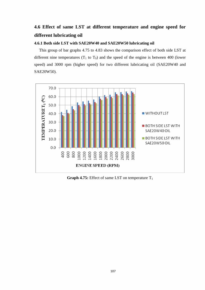
107
4.6 Effect of same LST at different temperature and engine speed for
different lubricating oil
4.6.1 Both side LST with SAE20W40 and SAE20W50 lubricating oil
This group of bar graphs 4.75 to 4.83 shows the comparison effect of both side LST at
different nine temperatures (T1 to T9) and the speed of the engine is between 400 (lower
speed) and 3000 rpm (higher speed) for two different lubricating oil (SAE20W40 and
SAE20W50).
Graph 4.75: Effect of same LST on temperature T1

108
Graph 4.76: Effect of same LST on temperature T2
Graph 4.77: Effect of same LST on temperature T3

109
Graph 4.78: Effect of same LST on temperature T4
Graph 4.79 Effect of same LST on temperature T5

110
Graph 4.80: Effect of same LST on temperature T6
Graph 4.81: Effect of same LST on lubrication oil temperature T7
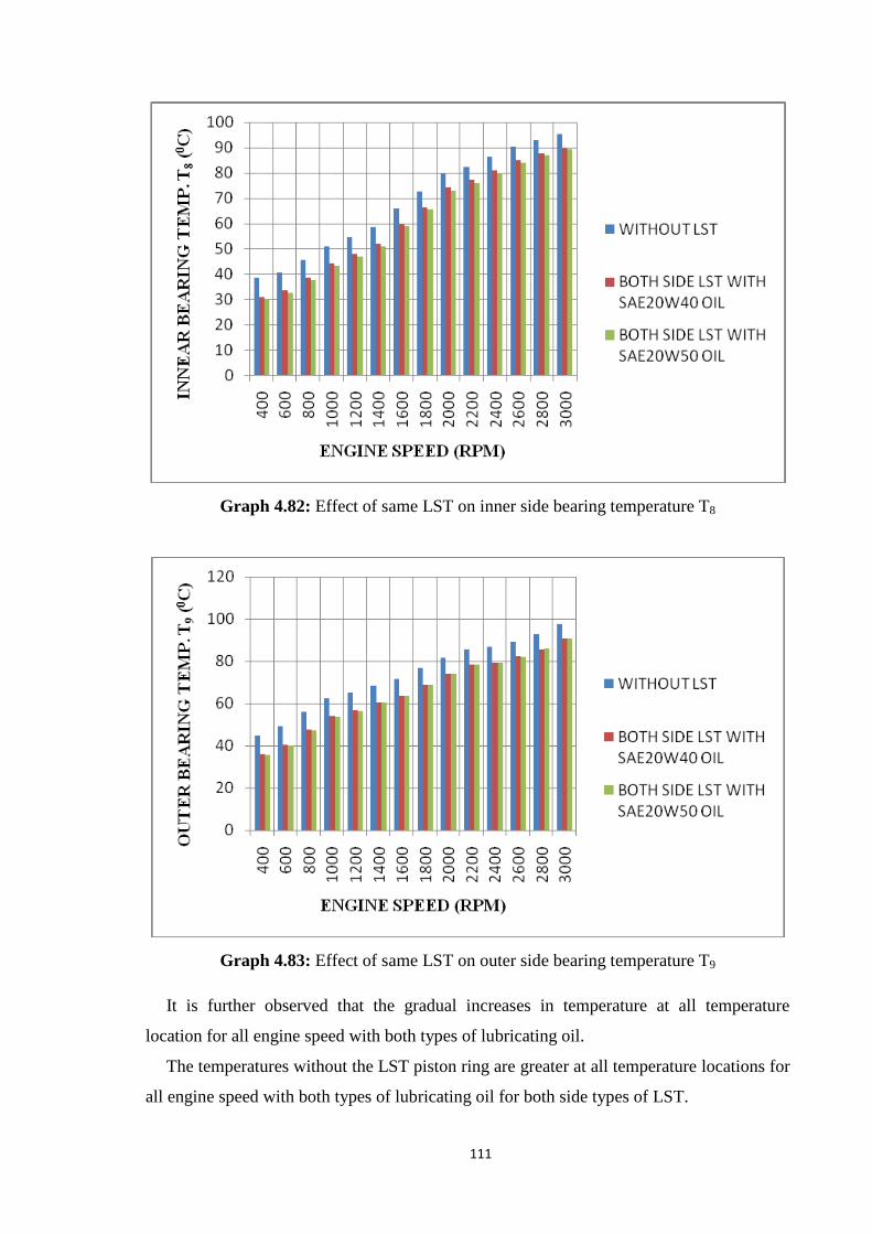
111
Graph 4.82: Effect of same LST on inner side bearing temperature T8
Graph 4.83: Effect of same LST on outer side bearing temperature T9
It is further observed that the gradual increases in temperature at all temperature
location for all engine speed with both types of lubricating oil.
The temperatures without the LST piston ring are greater at all temperature locations for
all engine speed with both types of lubricating oil for both side types of LST.

112
The temperature for SAE20W40 lubricating oil is higher than the temperature for
SAE20W50 lubricating oil for all conditions due to its lower viscosity at all temperatures.
It is observed from graph 4.75 to 4.80 for the temperature (T1 and T6) is that the
minimum temperature recorded 37.0°C cylinder-1 TDC (T1) at 400 rpm with SAE20W50
lubricating oil and maximum temperature recorded 96.5°C cylinder-2 BDC (T4) at 3000
rpm with normal piston ring.
From graph 4.81 for lubricating oil temperature, T7 minimum temperature noticed at
34.7°C at 400 rpm for both side LST with SAE20W40 lubricating oil and maximum
temperature noticed 98.2°C at 3000 rpm for outer side bearing temperature with normal
piston ring.
It is observed from graph 4.82 and 4.83 for the bearing temperature (T8 and T9) is that
the minimum temperature recorded 30.2°C at 400 rpm for inner side bearing temperature
with SAE20W50 lubricating oil and maximum temperature recorded 97.4°C at 3000 rpm
for outer side bearing temperature with normal piston ring.
4.6.2 Center portion LST with SAE20W40 and SAE20W50 lubricating oil
This group of bar graph 4.84 to 4.92 shows the comparison effect of center (middle)
portion LST at different nine temperatures (T1 to T9) and the speed of the engine is
between 400 (lower speed) and 3000 rpm (higher speed) for two different lubricating oil
(SAE20W40 and SAE20W50).
Graph 4.84: Effect of same LST on temperature T1

113
Graph 4.85: Effect of same LST on temperature T2
Graph 4.86: Effect of same LST on temperature T3
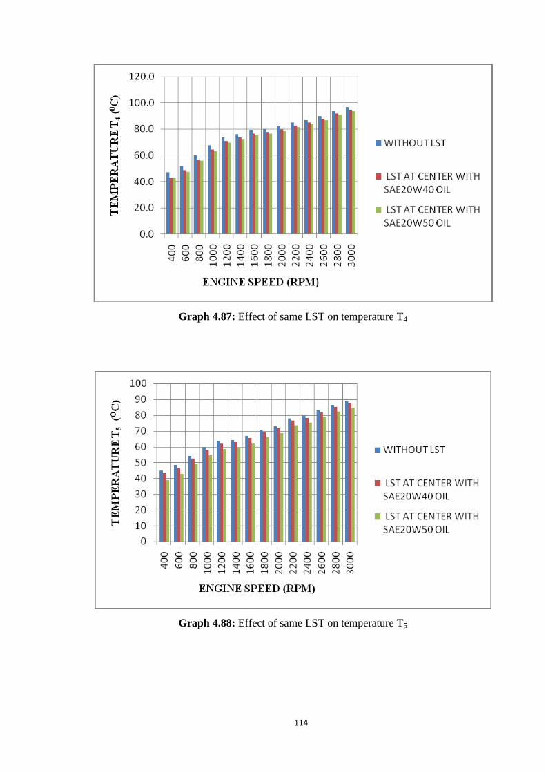
114
Graph 4.87: Effect of same LST on temperature T4
Graph 4.88: Effect of same LST on temperature T5
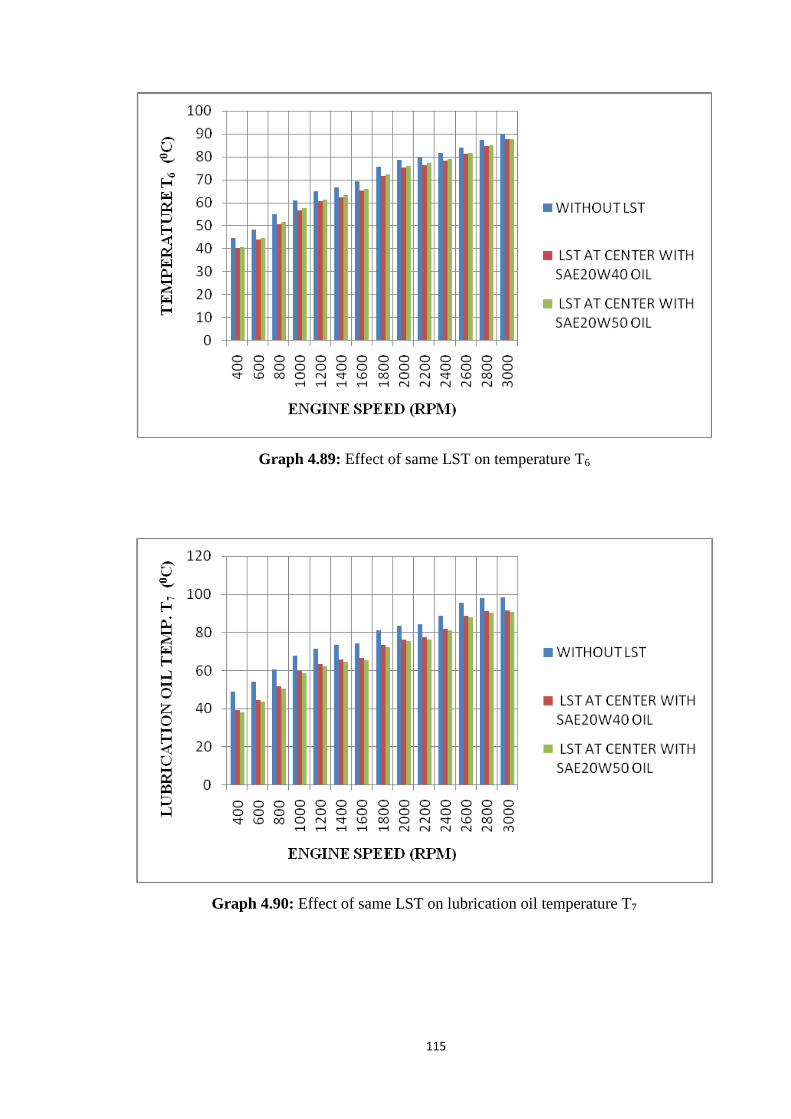
115
Graph 4.89: Effect of same LST on temperature T6
Graph 4.90: Effect of same LST on lubrication oil temperature T7

116
Graph 4.91: Effect of same LST on inner side bearing temperature T8
Graph 4.92: Effect of same LST on outer side bearing temperature T9
It is further observed that the gradual increases in temperature at all temperature
location for all engine speed with both types of lubricating oil.
The temperatures without the LST piston ring are greater at all temperature locations for
all engine speed with both types of lubricating oil for center (middle) portion LST.

117
The temperature for SAE20W40 lubricating oil is higher than the temperature for
SAE20W50 lubricating oil for all conditions due to its lower viscosity at all temperatures.
It is observed from graph 4.84 to 4.89 for the temperature (T1 and T6) is that the
minimum temperature recorded 37.8°C cylinder-1 TDC (T1) at 400 rpm with SAE20W50
lubricating oil and maximum temperature recorded 96.5°C cylinder-2 BDC (T4) at 3000
rpm with normal piston ring.
From graph 4.90 for lubricating oil temperature, T7 minimum temperature noticed at
38.3°C at 400 rpm for the center (middle) portion LST with SAE20W50 lubricating oil and
maximum temperature noticed 98.2°C at 3000 rpm for outer side bearing temperature with
normal piston ring.
It is observed from graph 4.91 and 4.92 for the bearing temperature (T8 and T9) is that
the minimum temperature recorded 31.2°C at 400 rpm for inner side bearing temperature
with SAE20W50 lubricating oil and maximum temperature recorded 97.4°C at 3000 rpm
for outer side bearing temperature with normal piston ring.
4.6.3 Full-width LST with SAE20W40 and SAE20W50 lubricating oil
This group of bar graphs 4.93 to 4.101 shows the comparison effect of full-width LST at
different nine temperatures (T1 to T9) and the speed of the engine is between 400 (lower
speed) and 3000 rpm (higher speed) for two different lubricating oil (SAE20W40 and
SAE20W50).
Graph 4.93: Effect of same LST on temperature T1

118
Graph 4.94: Effect of same LST on temperature T2
Graph 4.95: Effect of same LST on temperature T3

119
Graph 4.96: Effect of same LST on temperature T4
Graph 4.97: Effect of same LST on temperature T5

120
Graph 4.98: Effect of same LST on temperature T6
Graph 4.99: Effect of same LST on lubrication oil temperature T7

121
Graph 4.100: Effect of same LST on inner side bearing temperature T8
Graph 4.101: Effect of same LST on outer side bearing temperature T9

122
It is further observed that the gradual increases in temperature at all temperature
location for all engine speed with both types of lubricating oil.
The temperatures without the LST piston ring are greater at all temperature locations for
all engine speed with both types of lubricating oil for full-width LST.
The temperature for SAE20W40 lubricating oil is higher than the temperature for
SAE20W50 lubricating oil for all conditions due to its lower viscosity at all temperatures.
It is observed from graph 4.93 to 4.98 for the temperature (T1 and T6) is that the
minimum temperature recorded 38.1°C cylinder-1 TDC (T1) at 400 rpm with SAE20W50
lubricating oil and maximum temperature recorded 95.4°C cylinder-2 BDC (T4) at 3000
rpm with SAE20W40 lubricating oil.
From graph 4.99 for lubricating oil temperature, T7 minimum temperature noticed at
39.7°C at 400 rpm for full-width LST with SAE20W40 and SAE20W50 lubricating oil and
maximum temperature noticed 98.2°C at 3000 rpm for outer side bearing temperature with
normal piston ring.
It is observed from graph 4.100 and 4.101 for the bearing temperature (T8 and T9) is that
the minimum temperature recorded 32.8°C at 400 rpm for inner side bearing temperature
with SAE20W50 lubricating oil and maximum temperature recorded 97.4°C at 3000 rpm
for outer side bearing temperature with normal piston ring.

123
4.7 Effect of lubricating oil
4.7.1 Effect of different LST patterns at different temperature and engine speeds for
SAE20W40 lubricating oil
The below a group of bar graph 4.102 to 4.110 depicts the comparison effect of
different LST patterns at different temperature (T1 to T9) and engine speeds from 400 rpm
(lower speed) to 3000 rpm (higher speed) for SAE20W40 lubricating oil
Graph 4.102: Effect of different LST on temperature T1
Graph 4.103: Effect of different LST on temperature T2
SAE20W40
lubricating oil
SAE20W40
lubricating oil

124
Graph 4.104: Effect of different LST on temperature T3
Graph 4.105: Effect of different LST on temperature T4
SAE20W40
lubricating oil
SAE20W40
lubricating oil
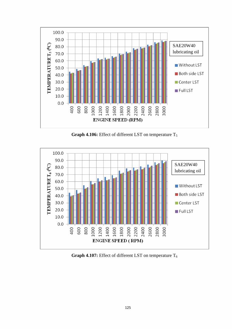
125
Graph 4.106: Effect of different LST on temperature T5
Graph 4.107: Effect of different LST on temperature T6
SAE20W40
lubricating oil
SAE20W40
lubricating oil
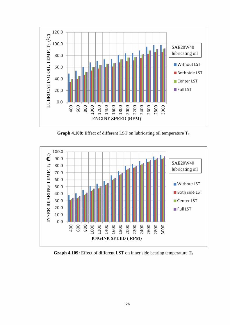
126
Graph 4.108: Effect of different LST on lubricating oil temperature T7
Graph 4.109: Effect of different LST on inner side bearing temperature T8
SAE20W40
lubricating oil
SAE20W40
lubricating oil
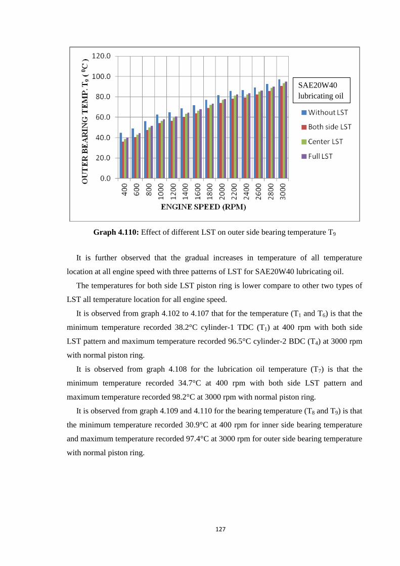
127
Graph 4.110: Effect of different LST on outer side bearing temperature T9
It is further observed that the gradual increases in temperature of all temperature
location at all engine speed with three patterns of LST for SAE20W40 lubricating oil.
The temperatures for both side LST piston ring is lower compare to other two types of
LST all temperature location for all engine speed.
It is observed from graph 4.102 to 4.107 that for the temperature (T1 and T6) is that the
minimum temperature recorded 38.2°C cylinder-1 TDC (T1) at 400 rpm with both side
LST pattern and maximum temperature recorded 96.5°C cylinder-2 BDC (T4) at 3000 rpm
with normal piston ring.
It is observed from graph 4.108 for the lubrication oil temperature (T7) is that the
minimum temperature recorded 34.7°C at 400 rpm with both side LST pattern and
maximum temperature recorded 98.2°C at 3000 rpm with normal piston ring.
It is observed from graph 4.109 and 4.110 for the bearing temperature (T8 and T9) is that
the minimum temperature recorded 30.9°C at 400 rpm for inner side bearing temperature
and maximum temperature recorded 97.4°C at 3000 rpm for outer side bearing temperature
with normal piston ring.
SAE20W40
lubricating oil

128
4.7.2 Effect of different LST patterns at different temperature and engine speeds for
SAE20W50 lubricating oil
The below a group of bar graphs 4.111 to 4.119 depicts the comparison effect of different
LST patterns at different temperatures (T1 to T9) and engine speeds from 400 rpm (lower
speed) to 3000 rpm (higher speed) for SAE20W50 lubricating oil.
Graph 4.111: Effect of different LST on temperature T1
Graph 4.112: Effect of different LST on temperature T2
SAE20W50
lubricating oil
SAE20W50
lubricating oil

129
Graph 4.113: Effect of different LST on temperature T3
Graph 4.114: Effect of different LST on temperature T4
SAE20W50
lubricating oil
SAE20W50
lubricating oil
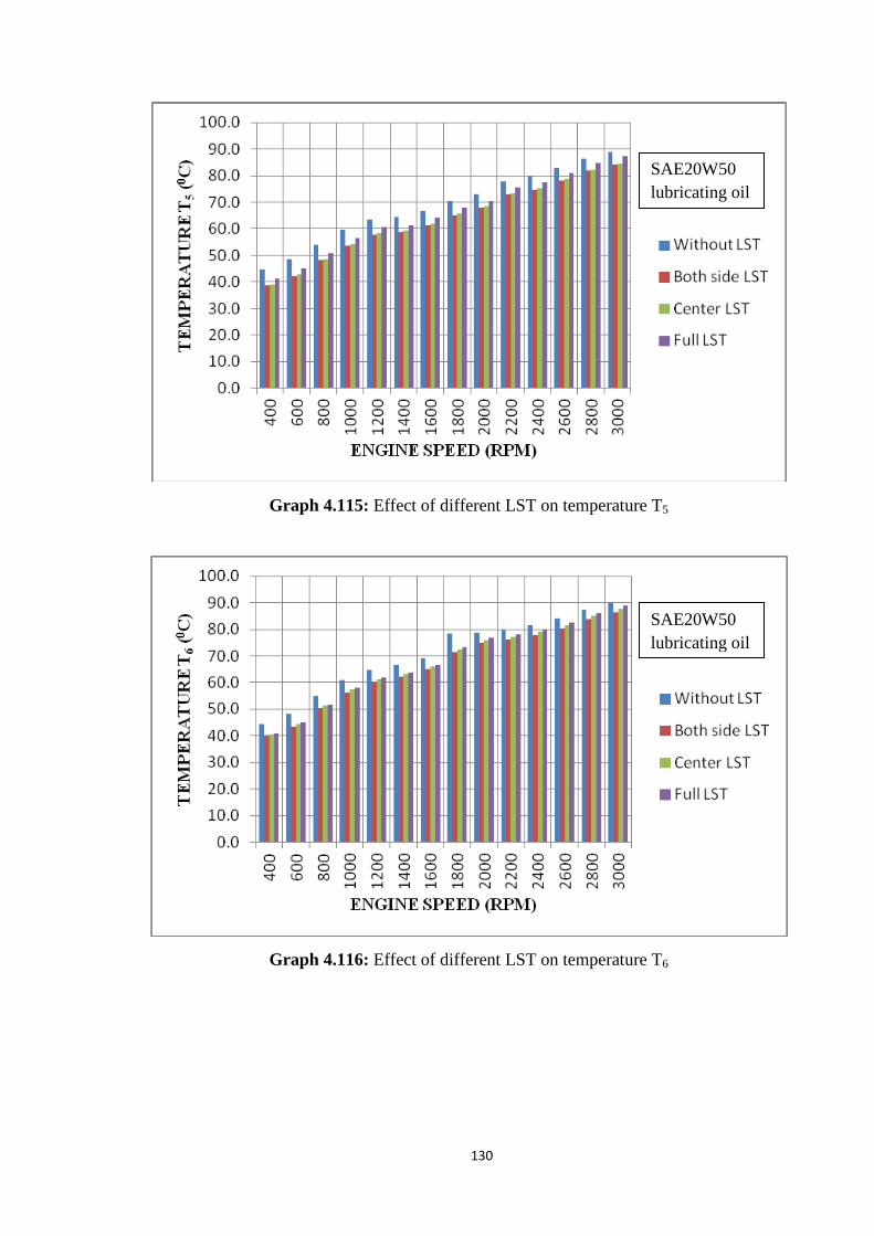
130
Graph 4.115: Effect of different LST on temperature T5
Graph 4.116: Effect of different LST on temperature T6
SAE20W50
lubricating oil
SAE20W50
lubricating oil

131
Graph 4.117: Effect of different LST on lubricating temperature T7
Graph 4.118: Effect of different LST on inner side bearing temperature T8
SAE20W50
lubricating oil
SAE20W50
lubricating oil

132
Graph 4.119: Effect of different LST on outer side bearing temperature T9
It is further observed that the gradual increases in temperature of all temperature
location at all engine speed with three patterns of LST for SAE20W50 lubricating oil.
The temperatures for both side LST piston ring is lower compare to other two types of
LST all temperature location for all engine speed.
It is observed from graph 4.111 to 4.116 that for the temperature (T1 and T6) is that the
minimum temperature recorded 37.0°C cylinder-1 TDC (T1) at 400 rpm with both side
LST pattern and maximum temperature recorded 94.9°C cylinder-2 BDC (T4) at 3000 rpm
with full-width LST.
It is observed from graph 4.117 for the lubrication oil temperature (T7) is that the
minimum temperature recorded 36.7°C at 400 rpm with both side LST pattern and
maximum temperature recorded 98.2°C at 3000 rpm with normal piston ring.
It is observed from graph 4.118 and 4.119 for the bearing temperature (T8 and T9) is that
the minimum temperature recorded 30.2°C at 400 rpm for inner side bearing temperature
and maximum temperature recorded 97.4°C at 3000 rpm for outer side bearing temperature
with normal piston ring.
SAE20W50
lubricating oil

133
4.8 Comparison of the effects of different LST on power consumed
Comparison between the use of LST in piston ring and with the use of LST is presented
in this section graph-4.120 shows the variations of friction power consumption v/s engine
speed for various LST methods applied on the piston rings.
Graph 4.120: Effect on power consumed [KW] of various textured surfaces and without a
textured surface
It is clearly shown that when the speed of the engine increases, at the same time the
friction power consumption increases hence, the trends are shown equally in all four cases.,
Minimum friction power consumption at 400 engine speed (low speed) and maximum
friction power consumption at 3000 engine speed (high speed) in all four cases.
The friction power consumption with a normal piston ring is greater compare to the
laser surface texture piston ring at all observed engine speed.
It is also noted that the power consumption for friction, increments from 0.60KW to
4.30KW as the speed of the engine increments from 400 revolutions of the engine to 3000
revolutions of the engine with no LST.
It is also noted that the power consumption for friction increases from 0.58KW to
4.10KW as the speed of the engine increases from 400 revolutions of the engine to 3000
revolutions of the engine with both sides LST, from 0.48KW to 4.00KW with center LST
and the relative values with full-width laser surface textures are 0.40KW and 3.90KW.

134
CHAPTER-5
CONCLUSIONS AND FUTURE SCOPE
5.1 Conclusions
The conclusions drawn from the present study are listed below. These results are at a
95% confidence level which is derived from the experiment analysis performed on
standard temperature and pressure condition. At the end of a long-run endurance test, it has
been proven that the full-width laser surface texturing piston ring can be successfully
replaced with a normal piston ring.
Seven series of experiments have been performed to investigate the advantage to use
LST in the reduction of friction. The first consists of without use texturing and the
remaining three contain texturing surfaces. Hence, first, one is taken as reference one for
comparison purposes with another three textured surfaces.
Referring to all results and observations for an experiment conducted under different
operating engine speed with a normal piston ring and different three-patterned laser surface
texturing piston ring.
[1] It is observed that, when the speed of the engine increases, at the same time the
friction power consumption increases hence, the trends are shown equally in all the cases.
The reason behind the increase in friction power consumption is the increment in
contact between the piston and the wall of the cylinder. This also found that, in the case of
the full-width LST method on the piston ring, the friction power consumption found
significantly lower as compared with both cases.
Without the use of LST, the whole surface of piston contact with a liner of the cylinder.
Hence, friction between piston and cylinder liner will be higher, hence the friction power
found higher. Here, in the case of symmetrically at both sides, only the edges of the piston
ring are in contact with the cylinder liner, hence friction found but not higher as compared
without of LST. A center portion of the piston ring normally grooves, hence both sides of
the contact with the cylinder liner, and therefore the friction will be less as compared with
the previous two cases. In the full-width case, the density of the LST will be lower due to

135
the area as compared with the previous three cases and found lower friction power
consumption.
Reduction in power consumption increases with an increase in engine speed. The laser
textured pistons result in an effective reduction of lubrication oil temperatures which may
contribute to improved lubrication oil life.
[2] The average percentage reduction in friction power with SAE20W40 and
SAE20W50 lubricating oil is found to be around 9% and 10% respectively by using both
side laser surface textured piston rings.
[3] When using center (middle) portion laser textured piston rings, the average
percentage reduction in friction power with SAE20W40 and SAE20W50 lubricating oil is
found to be about 15 % and 19 % respectively.
[4] By means of full-width laser piston textured rings, an average reduction in friction
power with SAE20W40 and SAE20W50 lubricating oil of 26% and 29% was found
respectively.
TABLE 5.1: Comparison of average reduction in friction power with different three
patterns with using two different grade of lubricating oil.
SAE20W40 Lubricating oil SAE20W50 Lubricating oil
Both Side LST 09% 10%
Centre (Middle)
portion LST
15% 19%
Full width LST 26% 29%
From this detailed study, it has been concluded that there is a substantial reduction in
the friction power of the engine with the use of LST on the piston rings. It is further
observed that with full width texturing on piston ring consumes 26% less power in
comparison to non-textured piston rings and similarly, 15% and 9% respectively in the
case of center portion LST and both sides LST with SAE20W40 lubricating oil. It is
further concluded that there is a definite effect of lubricating oil on the friction power
along with LST. With SAE20W50 lubricating oil, the percentage of reduction of friction
power for all three LST has been observed as 29%, 19%, and 10% respectively, that means
an additional reduction of 3% in case of full width LST, 4% with center portion LST and
1% with both sides LST is observed with SAE20W50.
[5] These reduced friction losses will lead to prolonged life of the engine by increasing
the life of pistons and increasing the efficiency of lubricating oil.
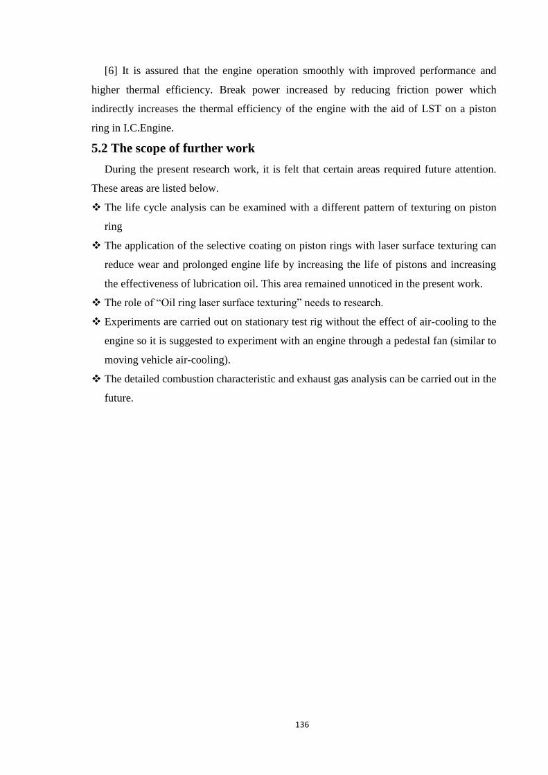
136
[6] It is assured that the engine operation smoothly with improved performance and
higher thermal efficiency. Break power increased by reducing friction power which
indirectly increases the thermal efficiency of the engine with the aid of LST on a piston
ring in I.C.Engine.
5.2 The scope of further work
During the present research work, it is felt that certain areas required future attention.
These areas are listed below.
The life cycle analysis can be examined with a different pattern of texturing on piston
ring
The application of the selective coating on piston rings with laser surface texturing can
reduce wear and prolonged engine life by increasing the life of pistons and increasing
the effectiveness of lubrication oil. This area remained unnoticed in the present work.
The role of “Oil ring laser surface texturing” needs to research.
Experiments are carried out on stationary test rig without the effect of air-cooling to the
engine so it is suggested to experiment with an engine through a pedestal fan (similar to
moving vehicle air-cooling).
The detailed combustion characteristic and exhaust gas analysis can be carried out in the
future.

137
CHAPTER-6
REFERENCES
01. G.Ryk, I.Etsion, Testing pistons rings with partial laser surface texturing for friction
reduction, Wear 261(2006)792-796
02. I. Etsion, E. Sher, Improving fuel efficiency with laser surface textured piston rings,
Tribology International 42(2009) 542-547
03. Y. Kligerman, I. Etsion, A. Shinkarenko, Improving tribological performance of piston
rings by partial surface texturing, J. Tribology Transactions ASME 127 (2005) 632–
638.
04. A. Ronen, I. Etsion, Y. Kligerman, Friction reducing surface texturing in reciprocating
automotive components, STLE Tribology Transactions 44 (2001) 359–366.
05. G.Ryk, Y. Kligerman, I.Etsion & A.Shikarenko (2005), Experimental investigation of
partial laser surface texturing for piston-ring friction reduction, STLE Tribology
Transactions 48 (2005) 583–585.
06. A.Ronen, Y. Kligerman, I. Etsion, Different approaches for analysis of friction in
surface textured reciprocating components.
07. V. Ezhilmaran, N.J. Vasa, L. Vijayaraghavan (2018), Investigation on generation of
laser-assisted dimples on piston ring surface and influence of dimple parameters on
friction. Surface & coatings technology (2018)1-35.
08. Sorin-Cristian Vladescu, Alessandra Ciniero, Khizer Tufail, Arup Gangopadhyay, Tom
Reddyhoff (2017) Looking into a laser textured piston ring-liner contact, Tribology
International 115 (2017) 140–153.
09. Nandakumar M. B, K. G. Sudhakar, Harshad Natu, Jagadish G. B(2018), Experimental
investigation of the effect of laser texturing on the used IC Engine Piston skirt,
Materials Today: Proceedings 5 (2018) 2773–2780
10.Ali Usman, Cheol Woo Park (2016) Numerical Investigation of Tribological
Performance in Mixed Lubrication of Textured Piston Ring‒Liner Conjunction with a
Non-circular Cylinder Bore, Tribology International
DOI: http://dx.doi.org/10.1016/j.triboint.2016.09.043

138
11.N. Morris, M. Leighton, R. Rahmani, M. De la Cruz, H. Rahnejat(2014), Friction
reduction in Piston Ring Cylinder Liner Contact using Textured Surfaces, Lubrication,
Maintenance and Tribotechnology, L14ICE068.
12.Haytam Kasem, Ori Stav, Philipp Grützmacher ID and Carsten Gachot(2018), Effect of
Depth Surface Texturing on Friction Reduction in Lubricated Sliding Contact Low,
Lubricants (2018), 6, 62.
13.B. Podgornik, M. Sedlacek (2012), Performance, Characterization, and Design of
Textured Surfaces, Journal of Tribology (October 2012), Vol. 134 / 041701-1-7.
14.Y. Wakuri, T. Hamatake, M. Soejima and T. Kitahara (1992), Piston ring friction in
internal combustion engines, Tribology International 1992, Vol. 25 No 5.
15.M. Priest, C.M. Taylor (2000), Automobile engine tribology — approaching the
surface, Wear 241 (2000), 193–203.
16.Staffan Johansson, Per H. Nilsson, Robert Ohlsson, Bengt-Goran Rosen (2011),
Experimental friction evaluation of cylinder liner/piston ring contact, Wear 271 (2011)
625–633.
17.Yuankai Zhou, Hua Zhu, Wei Tang, Chenbo Ma, Wenqian Zhang (2012), Development
of the theoretical model for the optimal design of surface texturing on cylinder liner.
Tribology International 52(2012) 1-6.
18.Francisco J. Profito, Sorin-Cristian Vladescu, Tom Reddyho, Daniele Dini (2016),
Transient experimental and modelling studies of laser-textured microgrooved surfaces
with a focus on piston-ring cylinder liner contacts, Tribology International. (Article in
press)
19.Eduardo Tomanik (2013), Modelling the hydrodynamic support of cylinder bore and
piston rings with laser textured surfaces, Tribology International 59 (2013), 90-96.
20.Zhi-Wei Guo, Cheng-Qing Yuan, Xiu-Qin Bai, Xin-Ping Yan (2018), Experimental
Study on Wear Performance and Oil Film Characteristics of Surface Textured Cylinder
Liner in Marine Diesel Engine, Chinese Journal of Mechanical Engineering, (2018)
31:52
21.Bifeng Yin, Xiaodong Li, Yonghong Fu and Wang Yun(2012), Effect of laser textured
dimples on the lubrication performance of cylinder liner in diesel engine, Lubrication
Science (2012), DOI: 10.1002/ls.1185
139
22.Khagendra Tripathi, Bhupendra Joshi, Gobinda Gyawali, Auezhan Amanov, Soo Wohn
Lee(2016), A study on the effect of laser surface texturing on friction and wear
behavior of graphite cast iron, Journal of Tribology (2016), Vol. 138 / 011601-1-10.
23.Yeau-Ren Jeng (2008), Impact of Plateaued Surfaces on Tribological Performance,
Tribology Transactions (2008), Vol. 39(1996), 2, 354-361.
24. L L. Ting, J. E. Mayer (1974), Piston ling lubrication and cylinder bore wear Analyses,
Part II—Theory verification, Journal of Lubrication Technology(1974), pg. 258-266.
25.Wan Yi, Xiong Dang-sheng (2008), The effect of laser surface texturing on frictional
performance of face seal. Journal of Materials Processing Technology 197 (2008) 96-
100.
26.A.Shikarenko, Y. Kligerman, I. Etsion (2009), The effect of surface texturing in soft
elasto-hydrodynamic lubrication. Tribology International 42 (2009) 284-292.
27.D. B. Hamilton, J. A. Walowit, C. M. Allen (1966), A Theory of Lubrication by Micro
irregularities, Journal of basic engineering(1966)177-185.
28.Martín Duarte, Andres Lasagni, Romain Giovanelli, Javier Narciso, Enrique Louis, and
Frank Mucklich (2008), Advanced engineering materials 2008, 10, No. 6, 554-558.
29.I.Krupka, R. Poliscuk, M. Hartl (2009), Behavior of thin viscous boundary films in
lubricated contacts between micro-textured surfaces, Tribology International 42 (2009)
535– 541.
30.Chunxing Gu, Xianghui Meng, Youbai Xie, Peng Li (2015), A study on the tribological
behavior of surface texturing on the nonflat piston ring under mixed lubrication, Proc
Institution of Mechanical Engineers Part J: Journal of Engineering Tribology(2015) pg
no. 1–20.
31.Parul Mishra & P. Ramkumar (2019), Effect of additives on a surface textured piston
ring–cylinder liner system, Tribology –Material, Surfaces & Interfaces.
https://doi.org/10.1080/17515831.2019.1588554
32.A.Shinkarenko, Y. Kligerman, I. Etsion(2009), The Validity of Linear Elasticity in
Analyzing Surface Texturing Effect for Elastohydrodynamic Lubrication, Journal of
Tribology (April 2009), Vol. 131 / 021503-1-7.
33.Xijun Hua, Jianguo, Sun, Peiyun Zhang, Kai Liu, Rong Wang, Jinghu Ji, Yonghong Fu
(2016), Tribological Properties of Laser Microtextured Surface Bonded With
Composite Solid Lubricant at High Temperature, Journal of Tribology (July 2016) Vol.
138 / 031302-1-11.

140
34.Naresh Panchal, Dheeraj Malav, Dr. Ashish Mathew (2016), Review of tribology
parameters in internal combustion engine, ICRTESM-2016 pg. 25-30.
35.Atul S. Shah, B. M. Sutaria, Dr. D.V. Bhatt(2009), Experimental Study and Analysis Of
Temperature Variation in Multicylinder Motorized Engine Test-Rig Under Different
Lubricants -A Case Study, Proceedings of the World Congress on Engineering 2009
Vol II.
36. Andriy Kovalchenko, Oyelayo Ajayi, Ali Erdemir, George Fenske (2011), Friction and
wear behavior of laser textured surface under lubricated initial point contact, Wear 271
(2011) 1719– 1725.
37.Ping Lu, Robert J. K. Wood, Mark G. Gee, Ling Wang, Wilhelm Pfleging (2018), A
Novel Surface Texture Shape for Directional Friction Control, Tribology Letters
(2018) 66:51
38.Wen-zhong Wang, Zhixiang Huang, Dian Shen, Lingjia Kong, Shanshan Li (2013), The
Effect of Triangle-Shaped Surface Textures on the Performance of the Lubricated
Point-Contacts, Journal of Tribology (APRIL 2013), Vol. 135 / 021503-1-11.
39.G. Ryk, Y. Kligerman, I. Etsion (2002), Experimental investigation of laser surface
texturing for reciprocating automotive components, Tribology Trans. 45 444–449.
40. Masahiko Nakada, Trends in engine technology and tribology, Tribology International
27(1) (1994) 3-8.
41. G.D. Knoll, H.J. Peeken(1982), Hydrodynamic lubrication of piston skirts, Journal of
lubrication technology transactions, ASME, Vol.104(4),504-509.
42. H. Mitsuru B.Yasukazu (1987), A study of piston friction force in an internal
combustion engine, ASLE transaction, 30(4), 444-51.
43. M. Takiguchi, K. Machida, S. Furuhama (1988), Piston friction force of a small high
speed gasoline engine, Tribology transaction, ASME, Vol-110:112-118.
44. Y. R. Jeng(1996), Impact of plateaued surfaces on tribological performance, Tribology
Transaction, 39(2),354-361.
45. Eric willis (1986), Surface finish in relation to cylinder liners, wear,109,351-366.
46. NW Bolander, F. Sadeghi (2007), Deterministic modelling of honed cylinder liner
friction, Tribology transaction, 50(2), 248-256.
47. G. duffet, P. Sallamand, A B Vannes (2003), Improvement in friction by cw Nd: YAG
laser surface treatment on cast iron cylinder bore, Applied surface science,205(1-
4),289-296.
141
48. H. Rahnejat, S Balakrishnan, P D King, S. Howell-smith (2006), In cylinder friction
reduction using a surface finish optimization technique, Proc IMechE part-D journal of
automobile engineering,220(9),1309-1318.
49. Kristian tonder (2001), Inlet roughness trio devices: dynamic coefficients and leakage,
Tribology international, 34,847-852.
50. U. Pettersson, S. Jacobson (2006), Tribological texturing of steel surfaces with a novel
diamond embossing tool technique, Tribology international,39,695-700.
51. Eduardo Tomanik (2008), Friction and wear bench tests of different engine liner
surface finishes, Tribology international, 41, 1032-1038.
52. Marko Sedlacek, Luis Miguel silva vilhena, Bojan podgornik, Joze vizintin (2011),
Surface topography modelling for reduced friction, Journal of mechanical
engineering,57,674-680.
53. Staffan Johansson, Per H. Nilsson, Robert Ohlsson, Bengt Goran Rosen (2017), A
novel approach to reduction of frictional losses in a heavy-duty diesel engine by
reducing the hydrodynamic frictional losses, Advances in tribology, Article ID
9240703, 17 pages.
54. Izhak Etsion (2005), State of the art in laser surface texturing -Technology review,
Journal of tribology, vol.-127,248-553.

142
Appendix A
Experimental data
OBSERVATION TABLE NO:1
TABLE: A.1 Piston rings without laser surface texturing
Sr.
No.
Engine
Speed
rpm
Power
Consumed
(KW)
Temperature at Different 9 locations o C
T1 T2 T3 T4 T5 T6 T7 T8 T9
1 400 0.60 42.0 45.5 46.1 47.0 44.8 44.5 48.8 38.4 44.8
2 600 0.70 44.5 49.6 49.9 52.1 48.4 48.2 54.0 40.6 49.0
3 800 0.90 48.7 56.5 56.1. 60.0 54.1 55.0 60.5 45.4 56.0
4 1000 1.10 53.1 63.2 62.0 67.5 59.6 60.9 68.0 51.0 62.5
5 1200 1.30 54.3 66.5 65.5. 73.7 63.6 64.8 71.3 54.4 65.0
6 1400 1.50 55.3 68.8 66.2 76.3 64.3 66.5 73.6 58.5 68.6
7 1600 1.70 56.6 70.8 67.8 79.4 66.8 69.1 74.3 65.9 71.7
8 1800 1.80 60.2 74.3 74.6 80.3 70.5 75.5 81.0 72.5 76.9
9 2000 2.10 61.9 75.1 76.3 82.2 73.0 78.7 83.6 79.5 81.6
10 2200 2.30 62.4 77.4 77.9 85.0 77.9 79.9 84.2 82.3 85.8
11 2400 2.70 65.2 79.5 80.4 87.3 79.6 81.6 88.8 86.3 86.7
12 2600 3.00 65.3 81.7 82.6 90.0 82.9 84.0 95.4 90.3 89.4
13 2800 3.30 66.0 84.8. 85.2 94.0 86.4 87.4 97.8 93.0 92.8
14 3000 4.30 66.6 87.0 87.2 96.5 88.8 89.9 98.2 95.2 97.4

143
OBSERVATION TABLE NO: 2
TABLE: A.2 Piston rings with laser surface texturing at both sides with using SAE20W40
lubricating oil.
Sr.
No.
Engine
Speed
RPM
Power
consumed
(KW)
Temperature at different 9 locations in oC
T1 T2 T3 T4 T5 T6 T7 T8 T9
1 400 0.58 38.2 39.7 40.1 41.1 42.2 39.4 34.7 30.9 36.1
2 600 0.67 40.9 43.9 44.0 46.3 45.9 43.2 40.0 33.3 40.4
3 800 0.86 45.2 50.9 50.3 54.4 51.6 50.1 46.7 38.4 47.5
4 1000 1.05 50.0 57.6 56.4 62.1 57.1 56.2 54.3 44.2 54.1
5 1200 1.24 51.2 61.0 60.2 68.5 61.2 60.2 57.7 47.7 56.7
6 1400 1.44 52.3 63.6 61.0 71.2 61.9 62.0 60.2 52.0 60.4
7 1600 1.62 53.7 65.7 62.7 74.4 64.5 64.6 61.2 59.5 63.7
8 1800 1.71 57.6 69.4 69.6 75.4 68.2 71.1 68.1 66.3 69.0
9 2000 2.00 59.4 70.3 71.4 77.5 70.7 74.4 70.8 74.4 73.9
10 2200 2.18 60.0 72.7 73.1 80.4 75.7 75.7 71.6 77.1 78.3
11 2400 2.56 62.9 75.0 75.6 82.7 77.4 77.4 76.2 81.0 79.4
12 2600 2.84 63.1 77.4 77.9 85.5 80.8 79.9 83.0 84.8 82.3
13 2800 3.13 64.0 80.6 80.6 89.6 84.3 83.5 85.6 87.5 85.8
14 3000 4.11 64.8 83.0 82.7 92.2 86.8 86.1 86.2 89.5 90.6

144
OBSERVATION TABLE NO: 3
TABLE: A.3 Piston rings with laser surface texturing at both sides with using SAE20W50
lubricating oil.
Sr.
No.
Engine
Speed
RPM
Power
consumed
(KW)
Temperature at different 9 locations in oC
T1 T2 T3 T4 T5 T6 T7 T8 T9
1 400 0.58 37.0 38.6 38.0 40.4 38.7 39.8 36.7 30.2 35.6
2 600 0.67 39.6 43.7 41.9 45.6 42.3 43.5 42.0 32.5 40.0
3 800 0.86 43.8 50.7 48.2 53.7 48.1 50.4 48.8 37.4 47.1
4 1000 1.04 48.5 57.6 54.4 61.3 53.7 56.3 56.5 43.2 53.8
5 1200 1.20 49.8 61.4 58.0 67.6 57.9 60.3 59.9 46.8 56.4
6 1400 1.42 50.8 63.8 58.8 70.3 58.7 62.2 62.5 51.0 60.3
7 1600 1.61 52.2 66.0 60.5 73.5 61.3 65.0 63.5 58.7 63.5
8 1800 1.70 56.0 69.6 67.5 74.6 65.2 71.5 70.5 65.5 69.0
9 2000 1.98 57.8 70.5 69.3 76.7 67.8 74.8 73.2 72.8 73.9
10 2200 2.16 58.4 72.8 71.0 79.7 72.9 76.2 73.9 75.8 78.2
11 2400 2.54 61.4 75.0 73.7 82.0 74.7 77.8 78.7 79.9 79.2
12 2600 2.82 61.5 77.5 76.3 84.8 78.1 80.2 85.4 84.0 82.1
13 2800 3.12 62.3 80.8 79.1 88.9 81.8 83.7 88.0 86.9 85.9
14 3000 4.10 63.0 83.1 81.3 91.5 84.3 86.3 88.6 89.3 90.7

145
OBSERVATION TABLE NO: 4
TABLE: A.4 Piston ring with laser surface texturing at symmetrically center with using
SAE20W40 lubricating oil
Sr.
No.
Engine
Speed
RPM
Power
consumed
(KW)
Temperature at different 9 locations in oC
T1 T2 T3 T4 T5 T6 T7 T8 T9
1 400 0.50 40.4 42.6 44.6 43.1 43.0 40.0 39.5 32.6 38.5
2 600 0.60 42.9 46.7 48.4 48.7 46.6 43.7 44.7 34.8 42.9
3 800 0.80 47.3 53.7 54.7 56.7 52.4 50.6 51.7 39.7 50.1
4 1000 0.98 51.8 60.6 60.6 64.6 58.0 56.5 59.6 45.4 56.7
5 1200 1.18 53.0 64.0 64.1 70.9 62.0 60.5 63.4 48.9 59.4
6 1400 1.36 54.1 66.3 64.8 73.5 62.8 62.3 65.8 53.2 63.2
7 1600 1.56 55.4 68.6 66.6 76.7 65.4 65.1 66.6 61.0 66.6
8 1800 1.62 59.1 72.3 73.4 77.8 69.1 71.7 73.5 67.7 72.1
9 2000 1.92 60.8 73.5 75.0 79.8 71.7 75.1 76.4 74.8 76.9
10 2200 2.12 61.5 75.8 76.8 82.7 76.6 76.4 77.3 77.8 81.3
11 2400 2.50 64.3 78.0 79.5 85.0 78.3 78.3 82.0 82.0 82.4
12 2600 2.80 64.6 80.2 81.7 87.9 81.7 81.2 88.7 86.2 85.2
13 2800 3.10 65.3 83.3 84.4 91.9 85.3 84.7 91.1 89.3 88.9
14 3000 4.10 66.0 85.6 86.6 94.6 87.7 87.6 91.6 91.6 93.6

146
OBSERVATION TABLE NO: 5
TABLE: A.5 Piston ring with laser surface texturing at symmetrically center with using
SAE20W50 lubricating oil
Sr.
No.
Engine
Speed
RPM
Power
consumed
(KW)
Temperature at different 9 locations in oC
T1 T2 T3 T4 T5 T6 T7 T8 T9
1 400 0.48 37.8 41.9 39.6 42.6 38.9 40.6 38.3 31.2 37.0
2 600 0.58 40.4 46.1 43.5 47.7 42.7 44.4 43.7 33.5 41.5
3 800 0.78 44.8 53.0 49.7 55.8 48.7 51.4 50.7 38.5 48.7
4 1000 0.95 49.4 59.9 55.7 63.3 54.4 57.4 58.6 44.4 55.6
5 1200 1.15 50.7 63.4 59.4 69.6 58.4 61.3 62.4 47.7 58.4
6 1400 1.32 51.7 65.7 60.2 72.3 59.3 63.1 64.8 52.2 62.1
7 1600 1.52 53.1 67.9 62.0 75.5 61.9 65.9 65.6 60.0 65.6
8 1800 1.60 56.9 71.5 68.8 76.5 65.8 72.4 72.4 66.8 70.8
9 2000 1.90 58.7 72.4 70.7 78.6 68.5 75.8 75.5 73.8 75.7
10 2200 2.08 59.2 74.8 72.5 81.5 73.5 77.1 76.4 76.8 80.1
11 2400 2.46 62.1 76.9 75.0 84.0 75.2 79.0 81.0 81.0 81.0
12 2600 2.74 62.4 79.2 77.3 86.9 78.6 81.6 87.8 85.2 84.2
13 2800 3.00 63.2 82.4 80.1 91.1 82.2 85.0 90.3 88.3 87.9
14 3000 4.00 64.0 84.7 82.1 93.8 84.6 87.6 90.8 90.6 92.9

147
OBSERVATION TABLE NO: 6
TABLE: A.6 Piston ring with laser surface texturing at full width with using SAE20W40
lubricating oil
Sr.
No.
Engine
Speed
RPM
Power
consumed
(KW)
Temperature at different 9 locations in oC
T1 T2 T3 T4 T5 T6 T7 T8 T9
1 400 0.40 40.6 43.0 44.7 43.7 43.2 40.9 39.7 34.2 40.2
2 600 0.49 43.3 47.5 48.5 49.4 47.0 44.7 45.0 36.5 44.5
3 800 0.68 47.8 54.5 54.8 57.4 52.8 51.9 51.8 41.5 51.7
4 1000 0.86 52.3 61.3 60.7 65.0 58.4 57.9 59.8 47.3 58.0
5 1200 1.05 53.5 64.7 64.3 71.4 62.5 62 63.5 50.8 60.7
6 1400 1.24 54.6 67.1 65.1 74.1 63.3 63.3 65.9 55.3 64.6
7 1600 1.44 55.9 69.1 66.8 77.3 65.9 66.1 66.8 62.9 67.8
8 1800 1.53 59.5 72.7 73.7 78.3 69.6 72.7 73.6 69.7 73.1
9 2000 1.82 61.3 73.6 75.5 80.3 72.2 76.2 76.6 76.9 77.9
10 2200 2.02 62.0 76.0 77.2 83.3 77.2 77.6 77.5 79.8 82.3
11 2400 2.41 64.9 78.1 79.8 85.7 78.9 79.8 82.2 84.0 83.4
12 2600 2.71 65.0 80.4 82.1 88.5 82.3 82.5 88.9 88.2 86.2
13 2800 3.00 65.8 83.6 84.8 92.7 85.9 86.1 91.4 91.0 89.9
14 3000 4.00 66.5 86.3 86.9 95.4 88.3 88.9 92.0 93.3 95.0

148
OBSERVATION TABLE NO: 7
TABLE: A.4 Piston ring with laser surface texturing full width with using SAE20W50
lubricating oil
Sr.
No.
Engine
Speed
RPM
Power
consumed
(KW)
Temperature at different 9 locations in oC
T1 T2 T3 T4 T5 T6 T7 T8 T9
1 400 0.40 38.1 42.4 40.7 43.1 41.2 40.9 39.7 32.8 39.0
2 600 0.48 40.8 46.7 44.5 48.3 44.9 44.9 45.0 35.3 43.5
3 800 0.68 45.2 53.6 50.8 56.4 50.8 51.8 51.7 40.3 50.7
4 1000 0.87 49.8 60.4 56.7 63.9 56.4 57.9 59.5 46.3 57.6
5 1200 1.06 51.3 63.7 60.4 70.2 60.5 61.9 63.0 49.9 60.4
6 1400 1.25 52.6 66.1 61.2 73.1 61.3 63.8 65.8 54.2 64.1
7 1600 1.42 54.1 68.1 62.9 76.4 64.0 66.6 66.6 62.0 67.4
8 1800 1.50 57.8 71.7 69.8 77.4 67.8 73.4 73.4 69.0 72.8
9 2000 1.78 59.6 72.6 71.7 79.4 70.5 76.8 76.3 76.2 77.7
10 2200 1.96 60.2 75.0 73.4 82.4 75.6 78.1 77.5 79.4 82.1
11 2400 2.35 63.0 77.1 76.0 84.8 77.6 79.9 82.3 83.7 83.1
12 2600 2.64 63.2 79.4 78.3 87.6 81.0 82.5 89.1 87.8 85.5
13 2800 2.92 63.9 82.6 81.1 91.7 84.7 86.2 92.3 90.7 90.1
14 3000 3.90 64.6 86.2 83.5 94.9 87.2 89.0 92.6 92.8 94.8

149
Appendix B
CALIBRATION
During the experimental work, a number of equipment was used. The following are the
instruments used and the calibration process was carried out for some of the instruments.
B.1 Digital Tachometer
A digital tachometer is a type of tachometer, a meteorological instrument used to
measure the revolution of the shaft of the engine [speed].
PHOTOGRAPH B.1: Digital tachometer
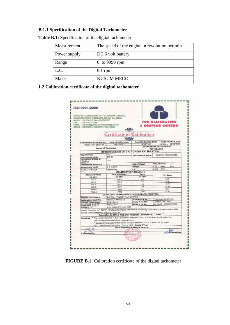
150
B.1.1 Specification of the Digital Tachometer
Table B.1: Specification of the digital tachometer
Measurement The speed of the engine in revolution per min.
Power supply DC 6 volt battery
Range 0 to 9999 rpm
L.C. 0.1 rpm
Make KUSUM MECO
1.2 Calibration certificate of the digital tachometer
FIGURE B.1: Calibration certificate of the digital tachometer

151
B.2 Temperature sensor (Infrared gun)
The temperature sensor is a device used for measuring the temperature of the
bearing inside the engine by using the principle of the radiation pyrometer.
Range:- (-) 10 o C to 100
o C
PHOTOGRAPH B.2: Temperature sensor (Infrared gun)
B.2.2 Calibration certificate of Temperature sensor (Infrared gun)
FIGURE B.2: Calibration certificate of Temperature sensor [Infrared gun]
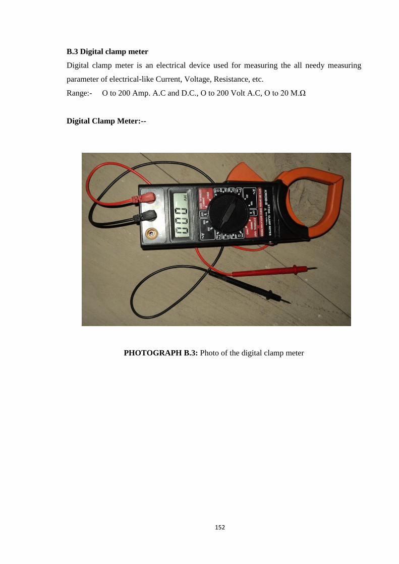
152
B.3 Digital clamp meter
Digital clamp meter is an electrical device used for measuring the all needy measuring
parameter of electrical-like Current, Voltage, Resistance, etc.
Range:- O to 200 Amp. A.C and D.C., O to 200 Volt A.C, O to 20 M.Ω
Digital Clamp Meter:--
PHOTOGRAPH B.3: Photo of the digital clamp meter

153
B.3.2 Calibration certificate of Digital Clamp meter
FIGURE B.3: Calibration certificate of Digital clamp meter

154
FIGURE B.4: Calibration certificate of Digital clamp meter

155
Appendix C
List of materials
List of material required for projects [Material Indent]
Table C.1 Lists of material required for projects
Sr. No. List of Material & parts Specification Units Quantity
1 Piston ring As per engine
[In standard set] Set 01
2 Laser surface textured
piston ring
Middle Portion Set 01
Symmetrical
both side Set 01
Full width Set 01
3 Oil Tank Gasket As per standard Nos. 04
4 High Temp. Bond Tube As per standard Nos. 04
5 Maruti Genuine Oil SAE
20W40 As per standard Tin 04
6 Castrol GTX Oil
SAE 20W50 As per standard Tin 04

156
Appendix D
Measuring instruments parameters
Table D1 shows the list of Instruments with accuracy, range, and percentage of errors.
Table D1: List of Instruments with accuracy, range, and percentage of errors
Instrument Accuracy or
LCM
Range % of
Error
RTD Type Temperature Sensor
[Thermocouple ]
+ 0.01oC -200 to 850
0C 0.05
Digital Tachometer 0.1 rpm 0 to 9999 rpm + 0.1
Variable Frequency Drive + 0.01 HZ
0 to 50/60 HZ
(Input Frequency)
0.5 to 500 HZ
(Output Frequency)
0.081
Infrared gun
+ 0.1oC
(-) 10 o C to 100
o C
+ 0.01
Digital Clamp meter
0.01 O to 200 Amp.
(A.C and D.C.),
O to 200 Volt A.C
O to 20 M.Ω
+0.01
Temperature Indicating Device
Sensor type :TC: Thermocouple
(K, J, T, R, or S)
Platinum resistance thermometer
(Pt100)
Indication
Accuracy :
+ 0.5% of PV
Sampling
Period :250ms
(-) 200 o
C to 1700o C + 0.001

157
Appendix E
Lists of publications
TABLE E.1: List of publication
Sr.
No
Title of the
Paper
Name of the
Authors
Name of
Journal
ISSN
Number
Month &
Year of
Publication
1 Laser Surface
Texturing (LST)
on Piston Rings
for Friction
Reduction- A
Technical Review
Vijay Kumar Patel,
Bharat M. Ramani
International
Journal of
Modern
Engineering
and Research
Technology
2348–
8565
Volume 5,
Issue 3,
July-2018
2 Investigation on
Laser Surface
Texturing for
friction reduction
in multi cylinder
Internal
Combustion
Engine
Vijay K. Patel,
Bharat M. Ramani
International
Journal of
Ambient
Energy
0143-
0750
November-
2019

158
3 Investigation on
Laser surface
texturing (LST)
for friction power
reduction in multi
cylinder
I.C.Engine
Vijay K. Patel,
Dr. Bharat M.
Ramani
Journal of
Tribology,
ASME
Journal
Communi
cated
4 Investigation and
performance
analysis of three
different patterns
of Laser surface
texturing on
piston ring
Vijay K. Patel,
Bharat M. Ramani
Friction Communi
cated