EXPERIMENTAL INVESTIGATION OF STALL … · experimental investigation of stall precursor-suppressed...
7
GPPF-2017-Put paper 059 EXPERIMENTAL INVESTIGATION OF STALL PRECURSOR-SUPPRESSED (SPS) CASING TREATMENT IN A TWO-STAGE AXIAL COMPRESSOR Dakun Sun Beihang University [email protected] Beijing, China Xu Dong Beihang University [email protected] Beijing, China Fanyu Li Beihang University [email protected] Beijing, China Xiaofeng Sun Beihang University [email protected] Beijing, China ABSTRACT In this paper, the effects of the stall precursor-suppressed (SPS) casing treatment on stall margin and efficiency are investigated experimentally in a two-stage axial compressor. The SPS casing treatment can improve the stall margin of the compressor by 3%-11% without significant efficiency loss. In addition, the mechanism of stall margin enhancement with such casing treatment is also revealed by observing the evolution of the precursor wave. INTRODUCTION In modern aeroengine design, high thrust and efficiency are usually pursued. At present, the compression ratio of a single stage fan/compressor can reach 2.2-2.4, and theoretically, the turbo-fan aeroengine of 15-20 thrust-weight ratio can be designed if the average stage pressure ratio reaches 1.85 [1]. However, since the birthday of F119, it is still impossible for manufactures to carry out a product with the thrust-weight ratio of 20. Obviously, fan/compressor must have higher blade loading under this situation. However, it is extremely difficult to meet the requirement of sufficient stall margin in a multi-stage compression system. Based on this concern, the flow stability problem of multi- stage compressor is the key issue for improving the holistic performance of modern turbo-machinery aeroengine. However, in the stall-onset prediction of multi-stage compressor, there are many difficulties in applying theoretical models and numerical simulations. Most of these difficulties are from some complex coupling of aerodynamic problems and structure problems. And the active control method [2-5] which is the most popular method in compressor stabilization nearly can not show any effect in multi-stage system. In a multi-stage compressor , it is really hard to detect and recognize the information of stall inception or stall onset. Casing treatment is an effective way to improve the stall margin. Since the famous observation about casing treatment was guided by Koch [6] in 1970, but most of casing treatment design has been based on trial and error experiences so far. Obviously a better design depends on the understanding of the mechanism. The existing investigations have pointed out another possibility that the mechanism will base on unsteady flow. With the development of numerical simulation technology, the design of modern casing treatment can be realized through numerical simulations, although it is really hard in doing with multi-stage compressor systems. In 2012, Gourdain [7] used unsteady RANS numerical simulation investigating the effects of tip clearance and casing treatment on compressor stability. The results showed that casing treatment could obviously improve the stability range of compressor and could even make up the stall margin loss caused by the increasing of tip clearance. But this work did give out the mechanism of rotating stall and casing treatment. Well, the application of experimental investigation method can not be easily transferred to multi-stage system from single-stage system. In 2003, Akhlaghi [8] carried out an experimental investigation of casing treatment on a three-stage compressor rig. This work used a casing treatment with annular back- chamber and guide vanes to research the effects of casing treatment at different axial positions relating to the rotor tip. Besides, when applying stabilization technology into multi- stage compressor, not only the stall margin should be taken into concern, but also the matching of each stage should be considered. Several years ago, Kroeckel [9] applied a traditional casing treatment into a 2-stage high-pressure This work is licensed under a Creative Commons Attribution 4.0 International License Creative Commons Attribution-NonCommercial-NoDerivatives 4.0 International License
-
Upload
phungnguyet -
Category
Documents
-
view
223 -
download
0
Transcript of EXPERIMENTAL INVESTIGATION OF STALL … · experimental investigation of stall precursor-suppressed...
Proceedings of the 1st Global Power and Propulsion Forum GPPF 2017
Jan 16-18, 2014, Zurich, Switzerland www.pps.global
GPPF-2017-Put paper 059
EXPERIMENTAL INVESTIGATION OF STALL PRECURSOR-SUPPRESSED (SPS) CASING TREATMENT IN A TWO-STAGE AXIAL COMPRESSOR
Dakun Sun Beihang University [email protected]
Beijing, China
Xu Dong Beihang University
[email protected] Beijing, China
Fanyu Li Beihang University [email protected]
Beijing, China
Xiaofeng Sun Beihang University [email protected]
Beijing, China
ABSTRACT In this paper, the effects of the stall precursor-suppressed
(SPS) casing treatment on stall margin and efficiency are investigated experimentally in a two-stage axial compressor. The SPS casing treatment can improve the stall margin of the compressor by 3%-11% without significant efficiency loss. In addition, the mechanism of stall margin enhancement with such casing treatment is also revealed by observing the evolution of the precursor wave.
INTRODUCTION In modern aeroengine design, high thrust and efficiency
are usually pursued. At present, the compression ratio of a single stage fan/compressor can reach 2.2-2.4, and theoretically, the turbo-fan aeroengine of 15-20 thrust-weight ratio can be designed if the average stage pressure ratio reaches 1.85 [1]. However, since the birthday of F119, it is still impossible for manufactures to carry out a product with the thrust-weight ratio of 20. Obviously, fan/compressor must have higher blade loading under this situation. However, it is extremely difficult to meet the requirement of sufficient stall margin in a multi-stage compression system. Based on this concern, the flow stability problem of multi-stage compressor is the key issue for improving the holistic performance of modern turbo-machinery aeroengine.
However, in the stall-onset prediction of multi-stage compressor, there are many difficulties in applying theoretical models and numerical simulations. Most of these difficulties are from some complex coupling of aerodynamic problems and structure problems. And the active control method [2-5] which is the most popular method in compressor stabilization nearly can not show any effect in multi-stage system. In a multi-stage compressor , it is really
hard to detect and recognize the information of stall inception or stall onset.
Casing treatment is an effective way to improve the stall margin. Since the famous observation about casing treatment was guided by Koch [6] in 1970, but most of casing treatment design has been based on trial and error experiences so far. Obviously a better design depends on the understanding of the mechanism. The existing investigations have pointed out another possibility that the mechanism will base on unsteady flow. With the development of numerical simulation technology, the design of modern casing treatment can be realized through numerical simulations, although it is really hard in doing with multi-stage compressor systems. In 2012, Gourdain [7] used unsteady RANS numerical simulation investigating the effects of tip clearance and casing treatment on compressor stability. The results showed that casing treatment could obviously improve the stability range of compressor and could even make up the stall margin loss caused by the increasing of tip clearance. But this work did give out the mechanism of rotating stall and casing treatment. Well, the application of experimental investigation method can not be easily transferred to multi-stage system from single-stage system. In 2003, Akhlaghi [8] carried out an experimental investigation of casing treatment on a three-stage compressor rig. This work used a casing treatment with annular back-chamber and guide vanes to research the effects of casing treatment at different axial positions relating to the rotor tip. Besides, when applying stabilization technology into multi-stage compressor, not only the stall margin should be taken into concern, but also the matching of each stage should be considered. Several years ago, Kroeckel [9] applied a traditional casing treatment into a 2-stage high-pressure
This work is licensed under a Creative Commons Attribution 4.0 International License Creative Commons Attribution-NonCommercial-NoDerivatives 4.0 International License
compressor. They found the casing treatment can enhance the stall margin obviously but the performance and flow field were also changed. And Kern [10] used the method of air injection at the blade tip region to realized the purpose of stabilization on a 8-stage high-pressure compressor. Although in that research, the 12 injectors could use 5% mass flow to gain 8.5% stall margin enhancement, but the matching of each stage was also be changed totally. Therefore, the existing technics can not be easily applied into multi-stage compression system.
Based on the small disturbance theory and vortex-pressure wave interaction suggestion, the relevant theoretical investigations have been carried out [11-15]. A three-dimensional axial-compressor stability model also has been developed, which is adopted to predict the onset point of rotating stall of a multi-rows compressor. It is possible to consider a complicated boundary condition in the stability model due to its three-dimensionality. The equivalent surface source method was introduced into the model to take account of the soft wall boundary condition. The advantage of this method is that it computes the scattering wave only through the eigen-value of solid wall instead of that of soft wall, so the related effect of casing treatments can be included in this way. So, the model can also help to design the geometric parameters of casing treatments. According to these results, the SPS casing treatment consisting of back-chamber and perforated plate is suggested. Compared with the conventional casing treatment aimed at the improvement of blade tip flow structure, the objective of the SPS casing treatment is to affect the evolution of the stall precursors in order to obtain stall margin improvement. The perforated ratio of the SPS casing treatment is only 4-10%, far smaller than in traditional casing treatments (with over 50% open area ratio). The relevant experiments [16-22] were conducted based on the SPS casing treatment, which is installed above the tip of the rotor blade. The results showed that the SPS casing treatment designed according to the results of theoretical research using the stability model of rotating stall can result in the stall margin improvement without efficiency loss. In the present investigation, the experiments of the SPS casing treatment on the two-stage low-speed fan TA66 are going to explore its stabilization ability on the multi-stage compression system.
EXPERIMENT FACILITIES
1 Ⅰ
11 1342 9
a
12
820mm320mm
50mm
14
5
6
3 Ⅱ8
7
b
c
10
d
0
Fig. 1 Structural schematic of TA66
All these present experimental work were carried out on a two-stage low-speed compressor TA66. Fig. 1 shows the structural schematic of this test rig. As the numbers
indicating in this figure, there are inlet guide vanes (item 3); first-stage rotor (item 4); first-stage stator (item 5); second-stage rotor (item 6); second-stage stator (item 7); inlet and outlet total pressure ranks (items 2 and 9); inlet and outlet static pressure probes (items 3 and 8); dynamic wall-static pressure sensors (items a/b/c/d); two SIMENS AC motors (item 14);two shafts (items 10 and 11) and outlet throttle valve (items 12 and 13 in). And Table 1 shows some structure and performance parameters.
Table 1 Structure and performance parameters of TA66 Structure Parameters
IGV 1R 1S 2R 2S Blade Number 38 47 45 47 45
Established Angle 0° 60° 10° 60° 10° External Diameter/mm 600 600 600 600 600
Span-chord Ratio 1.69 1.69 1.69 1.69 1.69 Hub-tip Ratio 0.7 0.7 0.7 0.7 0.7
Performance Parameters dm (kg/s) 7.5 dn 3000rpm
dφ 0.276 dψ 1.176 Power(kW) 16 η —
dπ∗ 1.056 2 1p p− 4675Pa
Rotor Tip Clearance 0.6~0.8mm tU 94.20m/s Rotor-Stator Axial Clearance 8-20mm
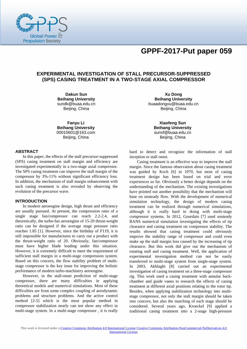
Fig. 2 shows the main steady pressure measurement probes, as the arrows indicating, the inlet/outlet static pressure can be measured averagely by 4 pressure sensors of each cross profile, and the inlet/outlet total pressure can be measured by two pressure ranks. All these total and static pressure sensors used here are 142PC01D Honeywell pressure sensors. These series sensors can provide an output voltage proportional to applied pressure. They operate from a single, positive supply voltage ranging from 7Vdc to 16Vdc. Signal conditioning results in directly usable outputs. Temperature compensation provides predictable performance over specified temperature ranges. And the rated pressure range is 1 PSI between two pressure ports (one port is atmosphere and another one is measured total/static pressure, so in the present work, pressures are measured with respect to an atmospheric pressure reference).
Fig. 2 Steady pressure measurement probes
2
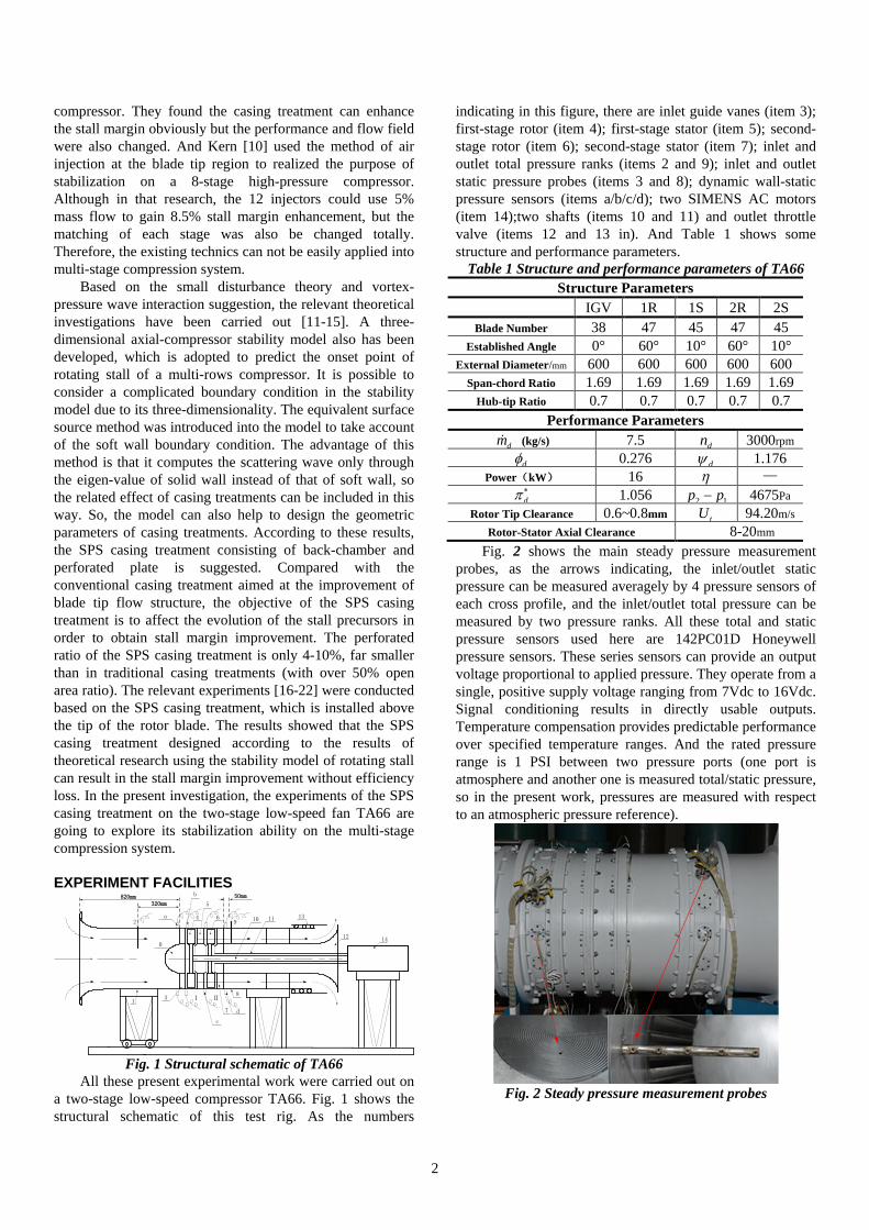
There are also 8 high frequency-response dynamic pressure sensors inlaid in the casing about half a chord length upstream of the rotor inlet of 4 cross profiles equally spaced around the circumference, as shown in Fig. 3. The model number of these 8 high-frequency response pressure sensors is XT-190M-1D, the rated pressure is 1 PSI in differential operational mode, and the sensitivity is about 5000.000mV/PSI.
Fig. 3 Dynamic pressure measurement sensors
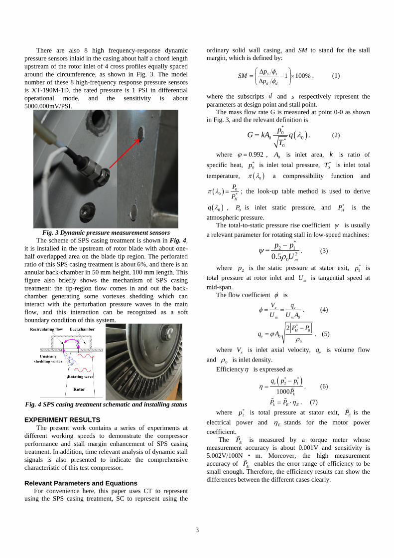
The scheme of SPS casing treatment is shown in Fig. 4, it is installed in the upstream of rotor blade with about one-half overlapped area on the blade tip region. The perforated ratio of this SPS casing treatment is about 6%, and there is an annular back-chamber in 50 mm height, 100 mm length. This figure also briefly shows the mechanism of SPS casing treatment: the tip-region flow comes in and out the back-chamber generating some vortexes shedding which can interact with the perturbation pressure waves in the main flow, and this interaction can be recognized as a soft boundary condition of this system.
Fig. 4 SPS casing treatment schematic and installing status
EXPERIMENT RESULTS The present work contains a series of experiments at
different working speeds to demonstrate the compressor performance and stall margin enhancement of SPS casing treatment. In addition, time relevant analysis of dynamic stall signals is also presented to indicate the comprehensive characteristic of this test compressor.
Relevant Parameters and Equations For convenience here, this paper uses CT to represent
using the SPS casing treatment, SC to represent using the
ordinary solid wall casing, and SM to stand for the stall margin, which is defined by:
1 100%s s
d d
pSM
pφφ
∆= − × ∆
. (1)
where the subscripts d and s respectively represent the parameters at design point and stall point.
The mass flow rate G is measured at point 0-0 as shown in Fig. 3, and the relevant definition is
( )*0
0 0*0
pG kA qT
λ= . (2)
where 0.992ϕ = , 0A is inlet area, k is ratio of specific heat, *
0p is inlet total pressure, *0T is inlet total
temperature, ( )0π λ a compressibility function and
( ) 00 *
H
PP
π λ = ; the look-up table method is used to derive
( )0q λ , 0P is inlet static pressure, and *HP is the
atmospheric pressure. The total-to-static pressure rise coefficient ψ is usually
a relevant parameter for rotating stall in low-speed machines: *
2 12
0
=0.5 m
p pU
ψρ−
. (3)
where 2p is the static pressure at stator exit, *1p is
total pressure at rotor inlet and mU is tangential speed at mid-span.
The flow coefficient φ is
0
x v
m m
V qU U A
φ = = . (4)
*0
00
2 Hv
P Pq Aϕ
ρ
−= .
(5)
where xV is inlet axial velocity, vq is volume flow and 0ρ is inlet density.
Efficiencyη is expressed as
( )* *2 1
1000v
k
q p p
Pη
−=
. (6)
k E EP P η= ⋅ . (7) where *
2p is total pressure at stator exit, EP is the electrical power and Eη stands for the motor power coefficient.
The EP is measured by a torque meter whose measurement accuracy is about 0.001V and sensitivity is 5.002V/100N · m. Moreover, the high measurement accuracy of EP enables the error range of efficiency to be small enough. Therefore, the efficiency results can show the differences between the different cases clearly.
3
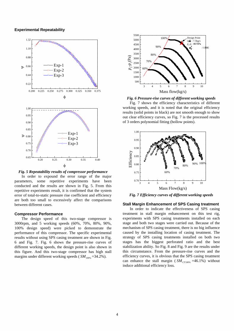
Experimental Repeatability
0.200 0.225 0.250 0.275 0.300 0.325 0.350 0.375
0.22
0.44
0.66
0.88
1.10
1.32
ψ
φ
Exp-1 Exp-2 Exp-3
0.20 0.25 0.30 0.35 0.400.65
0.70
0.75
0.80
0.85
0.90
0.95
1.00
ψ
φ
Exp-1 Exp-2 Exp-3
Fig. 5 Repeatability results of compressor performance
In order to expound the error range of the major parameters, some repetitive experiments have been conducted and the results are shown in Fig. 5. From this repetitive experiments result, it is confirmed that the system error of total-to-static pressure rise coefficient and efficiency are both too small to excessively affect the comparisons between different cases.
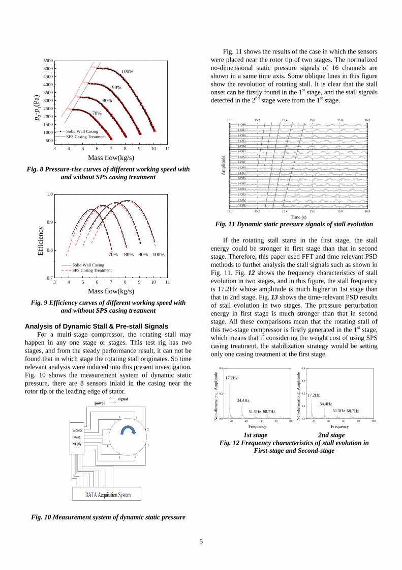
Compressor Performance The design speed of this two-stage compressor is
3000rpm, and 5 working speeds (60%, 70%, 80%, 90%, 100% design speed) were picked to demonstrate the performance of this compressor. The specific experimental results without using SPS casing treatment are shown in Fig. 6 and Fig. 7. Fig. 6 shows the pressure-rise curves of different working speeds, the design point is also shown in this figure. And this two-stage compressor has high stall margins under different working speeds ( 100%SM =34.2%).
3 4 5 6 7 8 9 10
500
1000
1500
2000
2500
3000
3500
4000
4500
5000
5500
100%
90%
80%
70%
p 2-p1(P
a)
Mass flow(kg/s)
60%
Design Point( : 7.5kg/sp2-p1:4675Pa
:1.056)
Fig. 6 Pressure-rise curves of different working speeds
Fig. 7 shows the efficiency characteristics of different working speeds, and it is noted that the original efficiency results (solid points in black) are not smooth enough to show out clear efficiency curves, so Fig. 7 is the processed results of 3 orders polynomial fitting (hollow points).
3 4 5 6 7 8 9 100.70
0.75
0.80
0.85
0.90
0.95
1.00
Ef
ficie
ncy
Mass Flow(kg/s)
60%70%
80% 90% 100%
Fig. 7 Efficiency curves of different working speeds
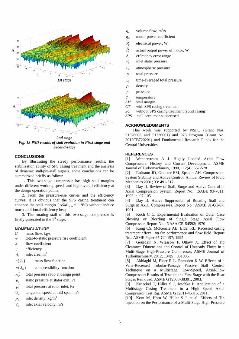
Stall Margin Enhancement of SPS Casing treatment In order to indicate the effectiveness of SPS casing
treatment in stall margin enhancement on this test rig, experiments with SPS casing treatments installed on each stage and both two stages were carried out. Because of the mechanism of SPS casing treatment, there is no big influence caused by the installing location of casing treatment. The strategy of SPS casing treatments installed on both two stages has the biggest perforated ratio and the best stabilization ability. So Fig. 8 and Fig. 9 are the results under this circumstance. From the pressure-rise curves and the efficiency curves, it is obvious that the SPS casing treatment can enhance the stall margin ( 100%CTSM =46.1%) without induce additional efficiency loss.
4
3 4 5 6 7 8 9 10 11
500
1000
1500
2000
2500
3000
3500
4000
4500
5000
5500
Solid Wall Casing SPS Casing Treatment
p 2-p1(P
a)
Mass flow(kg/s)
70%
80%
90%
100%
Fig. 8 Pressure-rise curves of different working speed with
and without SPS casing treatment
3 4 5 6 7 8 9 10 110.7
0.8
0.9
1.0
Solid Wall Casing SPS Casing Treatment
Effic
ienc
y
Mass flow(kg/s)
70% 80% 90% 100%
Fig. 9 Efficiency curves of different working speed with
and without SPS casing treatment
Analysis of Dynamic Stall & Pre-stall Signals For a multi-stage compressor, the rotating stall may
happen in any one stage or stages. This test rig has two stages, and from the steady performance result, it can not be found that in which stage the rotating stall originates. So time relevant analysis were induced into this present investigation. Fig. 10 shows the measurement system of dynamic static pressure, there are 8 sensors inlaid in the casing near the rotor tip or the leading edge of stator.
Fig. 10 Measurement system of dynamic static pressure
Fig. 11 shows the results of the case in which the sensors were placed near the rotor tip of two stages. The normalized no-dimensional static pressure signals of 16 channels are shown in a same time axis. Some oblique lines in this figure show the revolution of rotating stall. It is clear that the stall onset can be firstly found in the 1st stage, and the stall signals detected in the 2nd stage were from the 1st stage.
15.0 15.2 15.4 15.6 15.8 16.0
15.0 15.2 15.4 15.6 15.8 16.0
Time (s)
2-CH1
2-CH2
2-CH3
2-CH4
2-CH5
2-CH6
2-CH7
2-CH8
Am
plitu
de
1-CH1
1-CH2
1-CH3
1-CH4
1-CH5
1-CH6
1-CH7
1-CH8
Fig. 11 Dynamic static pressure signals of stall evolution
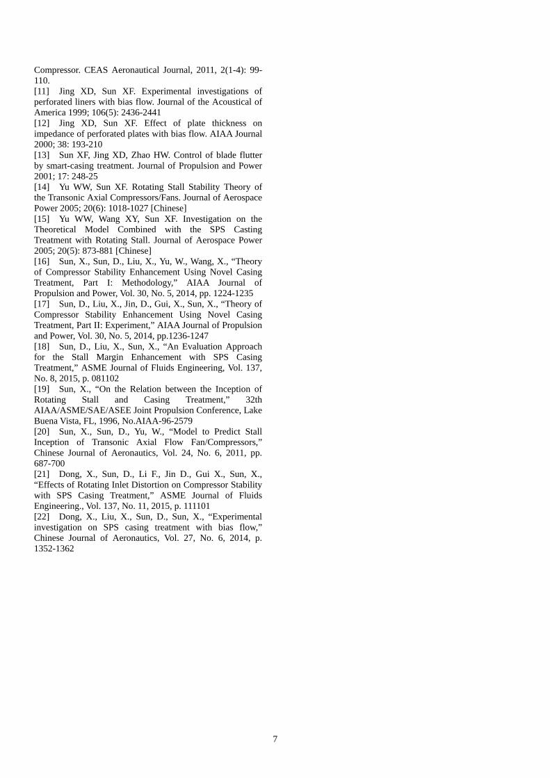
If the rotating stall starts in the first stage, the stall
energy could be stronger in first stage than that in second stage. Therefore, this paper used FFT and time-relevant PSD methods to further analysis the stall signals such as shown in Fig. 11. Fig. 12 shows the frequency characteristics of stall evolution in two stages, and in this figure, the stall frequency is 17.2Hz whose amplitude is much higher in 1st stage than that in 2nd stage. Fig. 13 shows the time-relevant PSD results of stall evolution in two stages. The pressure perturbation energy in first stage is much stronger than that in second stage. All these comparisons mean that the rotating stall of this two-stage compressor is firstly generated in the 1st stage, which means that if considering the weight cost of using SPS casing treatment, the stabilization strategy would be setting only one casing treatment at the first stage.
20 40 60 80 1000.0
0.2
0.4
Non
-dim
ensi
onal
Am
plitu
de
Frequency
17.2Hz
34.4Hz
51.5Hz 68.7Hz
20 40 60 80 1000.0
0.1
0.2
0.3
0.4
68.7Hz51.5Hz34.4Hz
Non
-dim
ensi
onal
Am
plitu
de
Frequency
17.2Hz
1st stage 2nd stage
Fig. 12 Frequency characteristics of stall evolution in First-stage and Second-stage
5
1st stage
2nd stage
Fig. 13 PSD results of stall evolution in First-stage and Second-stage
CONCLUSIONS By illustrating the steady performance results, the
stabilization ability of SPS casing treatment and the analysis of dynamic stall/pre-stall signals, some conclusions can be summarized briefly as follow:
1. This two-stage compressor has high stall margins under different working speeds and high overall efficiency at the design operation points;
2. From the pressure-rise curves and the efficiency curves, it is obvious that the SPS casing treatment can enhance the stall margin ( 100%SM∆ =11.9%) without induce much additional efficiency loss;
3. The rotating stall of this two-stage compressor is firstly generated in the 1st stage.
NOMENCLATURE G mass flow, kg/s ψ total-to-static pressure rise coefficient φ flow coefficient η efficiency
0A inlet area, m2
( )0q λ mass flow function
( )0π λ compressibility function *dπ total pressure ratio at design point
2p static pressure at stator exit, Pa *1p total pressure at rotor inlet, Pa
mU tangential speed at mid-span, m/s
0ρ inlet density, kg/m3
xV inlet axial velocity, m/s
vq volume flow, m3/s
Eη motor power coefficient
EP electrical power, W
kP actual output power of motor, W ∆ efficiency error range
0P inlet static pressure *
HP atmospheric pressure
tp total pressure
tp time-averaged total pressure ρ density p pressure T temperature SM stall margin CT with SPS casing treatment SC without SPS casing treatment (solid casing) SPS stall precursor-suppressed
ACKNOWLEDGMENTS This work was supported by NSFC (Grant Nos.
51576008 and 51236001) and 973 Program (Grant No. 2012CB720201) and Fundamental Research Funds for the Central Universities.
REFERENCES [1] Wennerstrom A J. Highly Loaded Axial Flow Compressors: History and Current Development. ASME Journal of Turbomachinery, 1990, 112(4): 567-578 [2] Paduano JD, Greitzer EM, Epstein AH. Compression System Stability and Active Control. Annual Review of Fluid Mechanics 2001; 33: 491-517 [3] Day IJ. Review of Stall, Surge and Active Control in Axial Compression System. Report No.: ISABE 93-7011; 1993. p. 97-105 [4] Day IJ. Active Suppression of Rotating Stall and Surge in Axial Compressors. Report No.: ASME 91-GT-87; 1991 [5] Koch C C. Experimental Evaluation of Outer Case Blowing or Bleeding of Single Stage Axial Flow Compressor. Report No.: NASA CR-54592; 1970 [6] Kang CS, McKenzie AB, Elder RL. Recessed casing treatment effect on fan performance and flow field. Report No.: ASME Paper 95-GT-197; 1995 [7] Gourdain N, Wlassow F, Ottavy X. Effect of Tip Clearance Dimensions and Control of Unsteady Flows in a Multi-Stage High-Pressure Compressor. ASME Journal of Turbomachinery, 2012, 134(5): 051005. [8] Akhlaghi M, Elder R L, Ramsden K W. Effects of a Vane-Recessed Tubular-Passage Passive Stall Control Technique on a Multistage, Low-Speed, Axial-Flow Compressor: Results of Tests on the First Stage with the Rear Stages Removed. ASME GT2003-38301, 2003. [9] Kroeckel T, Hiller S J, Jeschke P. Application of a Multistage Casing Treatment in a High Speed Axial Compressor Test Rig. ASME GT2011-46315, 2011. [10] Kern M, Horn W, Hiller S J, et al. Effects of Tip Injection on the Performance of a Multi-Stage High-Pressure
f t
A
f t
A
6
Compressor. CEAS Aeronautical Journal, 2011, 2(1-4): 99-110. [11] Jing XD, Sun XF. Experimental investigations of perforated liners with bias flow. Journal of the Acoustical of America 1999; 106(5): 2436-2441 [12] Jing XD, Sun XF. Effect of plate thickness on impedance of perforated plates with bias flow. AIAA Journal 2000; 38: 193-210 [13] Sun XF, Jing XD, Zhao HW. Control of blade flutter by smart-casing treatment. Journal of Propulsion and Power 2001; 17: 248-25 [14] Yu WW, Sun XF. Rotating Stall Stability Theory of the Transonic Axial Compressors/Fans. Journal of Aerospace Power 2005; 20(6): 1018-1027 [Chinese] [15] Yu WW, Wang XY, Sun XF. Investigation on the Theoretical Model Combined with the SPS Casting Treatment with Rotating Stall. Journal of Aerospace Power 2005; 20(5): 873-881 [Chinese] [16] Sun, X., Sun, D., Liu, X., Yu, W., Wang, X., “Theory of Compressor Stability Enhancement Using Novel Casing Treatment, Part I: Methodology,” AIAA Journal of Propulsion and Power, Vol. 30, No. 5, 2014, pp. 1224-1235 [17] Sun, D., Liu, X., Jin, D., Gui, X., Sun, X., “Theory of Compressor Stability Enhancement Using Novel Casing Treatment, Part II: Experiment,” AIAA Journal of Propulsion and Power, Vol. 30, No. 5, 2014, pp.1236-1247 [18] Sun, D., Liu, X., Sun, X., “An Evaluation Approach for the Stall Margin Enhancement with SPS Casing Treatment,” ASME Journal of Fluids Engineering, Vol. 137, No. 8, 2015, p. 081102 [19] Sun, X., “On the Relation between the Inception of Rotating Stall and Casing Treatment,” 32th AIAA/ASME/SAE/ASEE Joint Propulsion Conference, Lake Buena Vista, FL, 1996, No.AIAA-96-2579 [20] Sun, X., Sun, D., Yu, W., “Model to Predict Stall Inception of Transonic Axial Flow Fan/Compressors,” Chinese Journal of Aeronautics, Vol. 24, No. 6, 2011, pp. 687-700 [21] Dong, X., Sun, D., Li F., Jin D., Gui X., Sun, X., “Effects of Rotating Inlet Distortion on Compressor Stability with SPS Casing Treatment,” ASME Journal of Fluids Engineering., Vol. 137, No. 11, 2015, p. 111101 [22] Dong, X., Liu, X., Sun, D., Sun, X., “Experimental investigation on SPS casing treatment with bias flow,” Chinese Journal of Aeronautics, Vol. 27, No. 6, 2014, p. 1352-1362
7