Experimental Investigation of Interfacial Crack Arrest in ... · Accepted for publication in...
25
Accepted for publication in Journal of Sandwich Structures and Materials, 2016 Corresponding Author: Ole T. Thomsen, Faculty of Engineering and the Environment, University of Southampton, Highfield, Southampton, UK Email: [email protected] , web page: http://www.soton.ac.uk/engineering/ Experimental Investigation of Interfacial Crack Arrest in Sandwich Beams Subjected to Fatigue Loading using a Novel Crack Arresting Device G. Martakos 1 , J.H. Andreasen 1 , C. Berggreen 2 , O.T. Thomsen 3,1
Transcript of Experimental Investigation of Interfacial Crack Arrest in ... · Accepted for publication in...
Accepted for publication in Journal of Sandwich Structures and Materials, 2016
Corresponding Author:
Ole T. Thomsen, Faculty of Engineering and the Environment, University of Southampton, Highfield, Southampton, UK
Email: [email protected] , web page: http://www.soton.ac.uk/engineering/
Experimental Investigation of Interfacial Crack Arrest in Sandwich Beams Subjected to Fatigue Loading using a Novel Crack Arresting Device
G. Martakos1, J.H. Andreasen1, C. Berggreen2, O.T. Thomsen3,1
1Department of Mechanical and Manufacturing Engineering, Aalborg University
Fibigerstræde 16, DK-9220 Aalborg East, Denmark
Email: {gm,jha, ott}@aau.dk, web page: http://www.aau.dk
3Department of Mechanical Engineering, Technical University of Denmark
Nils Koppels Allé, Building 403, DK-2800 Kgs. Lyngby, Denmark
Email: [email protected], web page: http://www.mek.dtu.dk
3Faculty of Engineering and the Environment, University of Southampton, Highfield, Southampton, UK
Email: [email protected] , web page: http://www.soton.ac.uk/engineering/
Abstract A recently proposed face-sheet/core interface crack arresting device is implemented in sandwich beams and tested using the Sandwich Tear Test (STT) configuration. Fatigue loading conditions are applied to propagate the crack and determine the effect of the crack stopper on the fatigue growth rate and arrest of the crack. Digital image correlation is used through the duration of the fatigue experiment to track the strain evolution as the crack tip advances. The measured strains are related to crack tip propagation, arrest, and re-initiation of the crack. A finite element model is used to calculate the energy release rate, mode mixity and to simulate crack propagation and arrest of the crack. Finally the

effectiveness of the crack arresting device is demonstrated on composite sandwich beams subjected to fatigue loading conditions.
Keywords Sandwich structures, Finite Element Analysis, Composites, Fracture Mechanics, Fatigue
INTRODUCTION
Sandwich structures represent a special form of laminated composites comprising stiff and thin face-sheets separated by and bonded to either side of a light and compliant core material. The resulting layered sandwich element or structure displays very high stiffness and strength to weight ratios [1]. Their structural attributes and the need for larger and ever lighter structures has led to the implementation of sandwich structures into many areas of industrial production, i1)ncluding aerospace, ship/marine, automotive and wind turbine blade structures to mention a few. Due to their extensive and increasing use, novel ways to further enhance the performance of sandwich structures are being pursued continuously. Consequently the wish to fully understand the behaviour of sandwich structures is increasing, as well as the need to control and predict the effect of limitations and weaknesses inherent in their nature. One of the main limitations of sandwich structures is their high sensitivity to separation or debonding between the core material and the face-sheets. Localized loadings like bolt mounts or momentary overloads like impact loads can be responsible for introducing such debond damages in the structure. Debonds or dry spots can also be introduced during manufacturing, especially for larger parts. The separated or debonded zones effectively act as inherent structural weaknesses that often have no direct connection to the baseline mechanical properties of the constituent materials that comprise the structure. This study concerns the quantitative evaluation of a recently proposed face-sheet / core interface crack arresting device to be embedded in the sandwich core material [2-4], and which has the potential of significantly enhancing the damage tolerance of the sandwich structure.
The phenomenon of face-sheet /core separation or debonding (sometimes also referred to as “disbonding” or delamination) is frequently occurring as a so called bi-material or interfacial crack. Several studies have addressed the bi-material crack propagation and characterization problems. The earlier works of Erdogan [5] and Dundur [6] provided the theoretical background for examining crack behaviour in dissimilar materials. Later, Hutchinson and Suo [7], He and Hutchinson and Suo [8-9] and Wang [10] described the conditions for crack propagation and kinking of an interface crack for isotropic and orthotropic material constituents. Several works have being conducted using Finite Element Modelling to investigate interfacial crack initiation and propagation [11-13]. Berggreen [12] provided the theoretical background for the finite element analysis framework and introduced and implemented the Crack Surface Displacement Extrapolation method (CSDE) [14-15]. The method is used for calculating the energy release rate and mode mixity of a bi-material crack by using relative node displacements of the separated crack surfaces. Finally, Moslemian et al. [13-16] developed a cycle-jump
technique that together with the CSDE method was used to simulate fatigue crack growth in the face/core interfaces of sandwich structures.
Development of new testing methods to characterize face/core interface cracks in sandwich structures has been the focus of many studies. The Single Cantilever Beam test (SCB) [17-18], the Cracked Sandwich Beam test (CSB) [19], the Mixed Mode Bending test (MMB) [20-21] were used to apply different loading conditions to cracked sandwich beams. Most notably with the MMB test, the mode mixity applied can be constant and independent of the crack length making the test ideal for fatigue crack growth characterization [21-22]. Lastly Berggreen et al [14] introduced the Sandwich Tear Test (STT) to investigate crack propagation paths in different core materials. In this work, the STT configuration is used to examine the effect of the crack arresting device embedded in damaged composite sandwich beams.
Previous attempts to delay or arrest propagating face/core interface cracks by using special crack stopping core insert like devices have shown some promise, but they have been somewhat dependent on the applied loading conditions. Rinker et al [23] introduced two types of carbon fibre reinforced inserts loaded using the SCB and CSB tests for mode I and mode II loading conditions, respectively. It was shown that especially under mode II loading conditions the crack arresters could arrest the crack for a considerable number of loading cycles. This effect is mostly a consequence of the much higher fracture toughness of the CFRP arresters, in comparison with the core material, as well as of the specific geometry of the crack arresters. Hirose et al. [24-25] demonstrated that crack arrest can be achieved by using either a semi-circular CFRP rod glued on the face / core interface or a splice-type arrester connecting the two face-sheets of the sandwich beam through CFRP layers. In both cases a stress release from the crack tip was recorded as the crack approached the arresters. The reduction of stresses at the crack tip resulted in a reduction of the energy release rate and the deceleration of the crack. Despite the observed ability to arrest propagating interface cracks, major limitations arise from the inclusion of very high stiffness materials in the core structure of the sandwich component. As has been shown by Johannes at al. [26-27], core junctions in sandwich materials can lead to premature failure and crack initiations due to high stiffness differences.
An alternative approach aiming to impede interface crack propagation by using a material with stiffness properties close to those of sandwich core materials was introduced by Jakobsen et al. [2-3] and[28-32]. In this work the authors used a wedge shaped core insert made from Polyurethane (PU) resin, a low stiffness but highly ductile material, to deflect and arrest propagating interface cracks to the inner part of the sandwich core. The concept was successful as the required energy for a crack to penetrate the PU insert was relatively high due to the high ductility of the PU, while at the same time the similar stiffness properties of the core and the PU insert material and the low wedge angle adjacent to the face/core interface ensured that the locally induced stress concentrations were relatively modest. Jakobsen et al. [28-29] performed both static and fatigue tests with sandwich beams displaying mode II dominated interface crack propagation, and the ability of the crack arresting device (referred to as a peel stopper) to deflect a crack and arrest interface cracks was convincingly demonstrated under these
conditions. It was also shown that the principle could only work with insert materials processing low stiffness. A drawback of the peel stopper is that it is rather bulky, thus indicating that a significant weight penalty will be imposed to structures in which the concept is adopted. Furthermore, the manufacturing costs of implementing the proposed peel stopper may be considerable, making the concept un-attractive for low-cost applications like wind turbine blades and marine structures, but likely still to be of potential interest for high-cost applications like e.g. composite aero structures .
In the present study an improved crack stopper based on the peel stopper concept of Jakobsen et al [2-3 and 29-32] embedded in composite sandwich beams subjected to fatigue loading is investigated. The new crack stopper has been investigated experimentally and numerically by Wei et al. [4] for its ability to deflect and arrest a propagating face /core interface crack under both static and fatigue loading. In their work the loading conditions at the interface crack tip were Mode I dominated, which for many applications is considered a more realistic scenario than mode II. It was shown that the ability to deflect a propagating face /core interface crack is enhanced by reinforcing the connection (joint) between the crack arresting device (the peel stopper) and the face-sheet with glass fibres extending into or bonded to the face-sheet. The principal difference between the novel peel stopper proposed in [4] and that presented by Jakobsen et al [2-3] and [28-32] is that it involves much less material usage, and thus provides a much smaller weight penalty.
The findings from [4] are used in this study to ensure crack deflection away from the face /core interface and into the core. Although [4] involved extensive studies of the crack deflection capacity of the novel crack arrester (hereinafter referred to as a “peel stopper”), its overall capacity to contain a crack when subjected to a high number of loading cycles was not investigated. The reason is that the MBB test set-up used in [4] is ideal for highly controlled crack propagation tests [20-21], but does not allow for very large crack lengths. This prohibited the crack from advancing until (and beyond) the physical boundary of the peel stopper was reached. To circumvent this problem, in the research presented in this paper the STT set-up (Sandwich Tear Test [14]) is chosen due to its ability to allow for very large crack lengths. A drawback (or rather a validation challenge) of the STT test, when comparing with numerical simulation results, is that the physical crack propagation parameters, i.e. the energy release rate and mode mixity, cannot be specified independently during the testing. Thus, when using the STT test, the crack is allowed to propagate “freely” under fatigue loading conditions. The performance of the peel stopper is then evaluated based on its ability to deflect a propagating crack, as well as its ability to achieve crack arrest for a high number of loading cycles. The crack arrest behaviour is investigated by means of digital image correlation (DIC), where the strain distribution in the sandwich specimen surface around the crack arrest area is linked directly to the crack arresting performance.
METHODS

Test specimen-peel stopper
The face-sheets of the sandwich beam specimens were manufactured using 3 layers of glass fibre mats; face-sheet quad-mat (0/45/90/-45) from Devold, AMT (DBLT-850), providing a face-sheet thickness of 2 mm. The resin system used was Huntsman Araldite LY 1564 SP/Hardener XB 3486. For the core material, DIVINYCELL H100 PVC foam from DIAB was used, having a nominal density of 100kg/m3 [33].
The peel stopper was manufactured based on the novel design concept proposed in [4], and according to this its shape is chosen to be a thin strip of compliant Polyurethane (PU) reinforced with UD glass fibres as shown in Figure 1. The PU resin used for the peel stopper is Permalock 2K PU-9004. Using the PU/glass fibre hybrid material enables the peel stopper to display stiffness properties that are very similar to those of the foam core material, but at the same time having a higher fracture toughness. In accordance with [4], the fibres running along the peel stopper wedge (see Figure 1) are protruding from its tip. The goal of the new design is to improve the crack arresting ability without penalizing the overall structural weight.
Figure 1. Peel stopper shape and material alignment
The peel stopper is fabricated into shape in one piece using a specially designed closed mould tool. First, the embedded glass fibres are inserted into the open mould. Then, the PU resin is injected in the mould in excess amount. Finally the mould is closed and the PU resin is pressed into the shape of the mould tool impregnating the glass fibres at the same time. Steel clamps are used to apply the needed pressure to close the mould, while the excess PU material is allowed to exit from holes drilled along the length of the mould. The mould is made from Polyprolylene, a material that forms neither mechanical nor chemical bonds with PU resin. Therefore no special release or demolding agent is applied in the mould.
The sandwich beams were all cut from one sandwich panel which was fabricated in a two-step process. In the first step, the core of the sandwich panel including the peel stoppers was assembled. This process requires the PVC foam to be milled into the correct
shape to include the peel stopper. Then, the peel stopper was bonded to the PVC foam using a two-component epoxy glue, Araldite 2000.
In the second step, the final assembly of the sandwich panel components is made. The face-sheet and assembled core structure are placed in the right order, while a 25 μm thickness Teflon foil is placed between them. The Teflon foil is used to introduce a pre-cracked region across half the span of the specimen. When the TEFLON foil is placed, the core and face-sheets are infused by the epoxy resin using Vacuum Assisted Resin Transfer Moulding (VARTM). At this point the glass fibres protruding from the peel stoppers are effectively bonded to the face-sheet glass reinforcement during the epoxy resin infusion. Finally, the sandwich panel is cut into sandwich beam specimens that contain the peel stopper in the core structure. The material properties of the sandwich beam specimen components were measured, and the results are shown in table 1. The stiffness properties of the glass face sheet were obtained by conducting tension and V-notched shear tests is Technical University of Denmark (DTU) facilities. The Divinicell H100 foam stiffness properties were obtained by Siavash et al. [34] in Aalborg University. The stiffness of the PU was obtained by Jakobsen [32] by conducting a simple tension test and deriving the full stress strain curve of the material until failure .
Table 1. Sandwich beams material properties.
Materials
In-plane Young’s modulus
(Ex)
Through thickness Young’s modulus
(Ey)
Shear modulus
(Gxy)
Poisson’s ratio (vxy)
DIVINYCELL H100 56 MPa 128 MPa 32 MPa 0.2
E-glass/epoxy 18.6 GPa -- 2.7 GPa 0.4
PU 100 MPa 100 MPa -- --
STT setup In the STT [14] test the energy release rate and mode mixity at the crack tip are not changing monotonically as the crack length increases. This behaviour makes the STT test especially interesting for this work, since the objective is to investigate the effect of the novel peel stoppers on the fatigue life of sandwich structural components under generalized loading conditions. In previous works from Berggreen and Moslemian [14],[22,34] testing and simulation of the behaviour of the STT setup were conducted by using FE models both for static and fatigue loading conditions. In those studies though, the propagation of the crack was made in only one predefined bi-material interface to avoid uneven and unpredictable loading of the specimen and generation of moments at the load introduction point, when two cracks are propagating in the specimen. In the present study the interface cracks can also propagate in only one interface. However, the embedded peel stoppers can diverge the initial face/core interface crack away from the face/core interface and thus initiate a new crack path into the core along the peel stopper surface
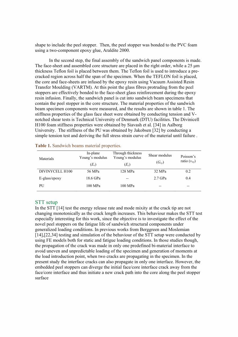
The STT specimen and setup is shown in Figure 2. The edges and middle of the sandwich specimen are clamped to the T-slot table of the testing machine, while the upper face-sheet is being pulled at mid-span by the testing machine piston. The Teflon foil introduced in manufacturing separates the core material from the pulled face-sheet allowing for only one crack to propagate towards the direction where the peel stopper is implemented in the core structure. The face-sheet on top of the debonded area is also clamped at its edge carrying high in-plane membrane forces, when the applied displacements are large.
Figure 2. STT specimen dimensions and test setup.
A four-column 100 kN MTS 319.25 with a T-slot table operated by a MTS FlexTest 60 controller and equipped with a 10 kN load cell was used to mount and load the STT specimens for both quasi-static and fatigue load testing. The specimens have a length of 700 mm, a height of 29 mm and a width of 47-50 mm, see Figure 2. At the edges of the sandwich beams the DIVINYCELL H100 foam has been replaced by wooden inserts to enable the imposing of appropriate clamping conditions (Figure 3). In the middle of the sandwich specimens, the foam has been removed completely to allow for the clamping of the lower face-sheet (Figure 3).
Digital Image Correlation (DIC)
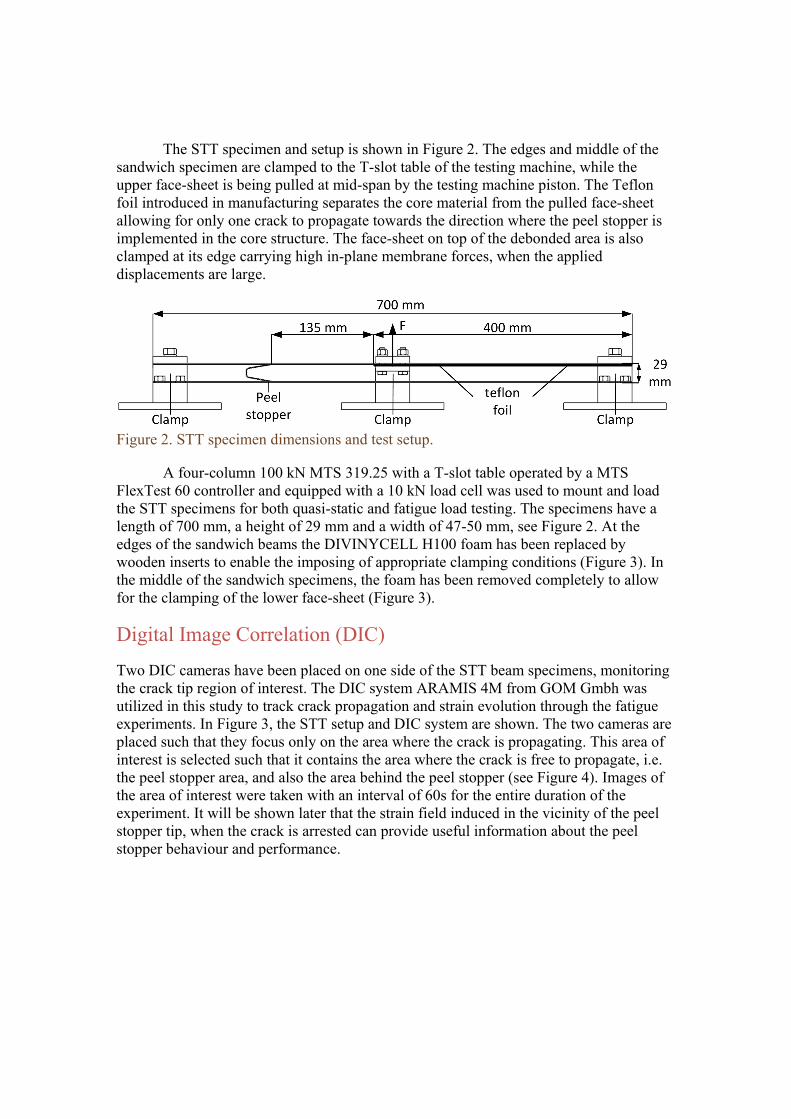
Two DIC cameras have been placed on one side of the STT beam specimens, monitoring the crack tip region of interest. The DIC system ARAMIS 4M from GOM Gmbh was utilized in this study to track crack propagation and strain evolution through the fatigue experiments. In Figure 3, the STT setup and DIC system are shown. The two cameras are placed such that they focus only on the area where the crack is propagating. This area of interest is selected such that it contains the area where the crack is free to propagate, i.e. the peel stopper area, and also the area behind the peel stopper (see Figure 4). Images of the area of interest were taken with an interval of 60s for the entire duration of the experiment. It will be shown later that the strain field induced in the vicinity of the peel stopper tip, when the crack is arrested can provide useful information about the peel stopper behaviour and performance.
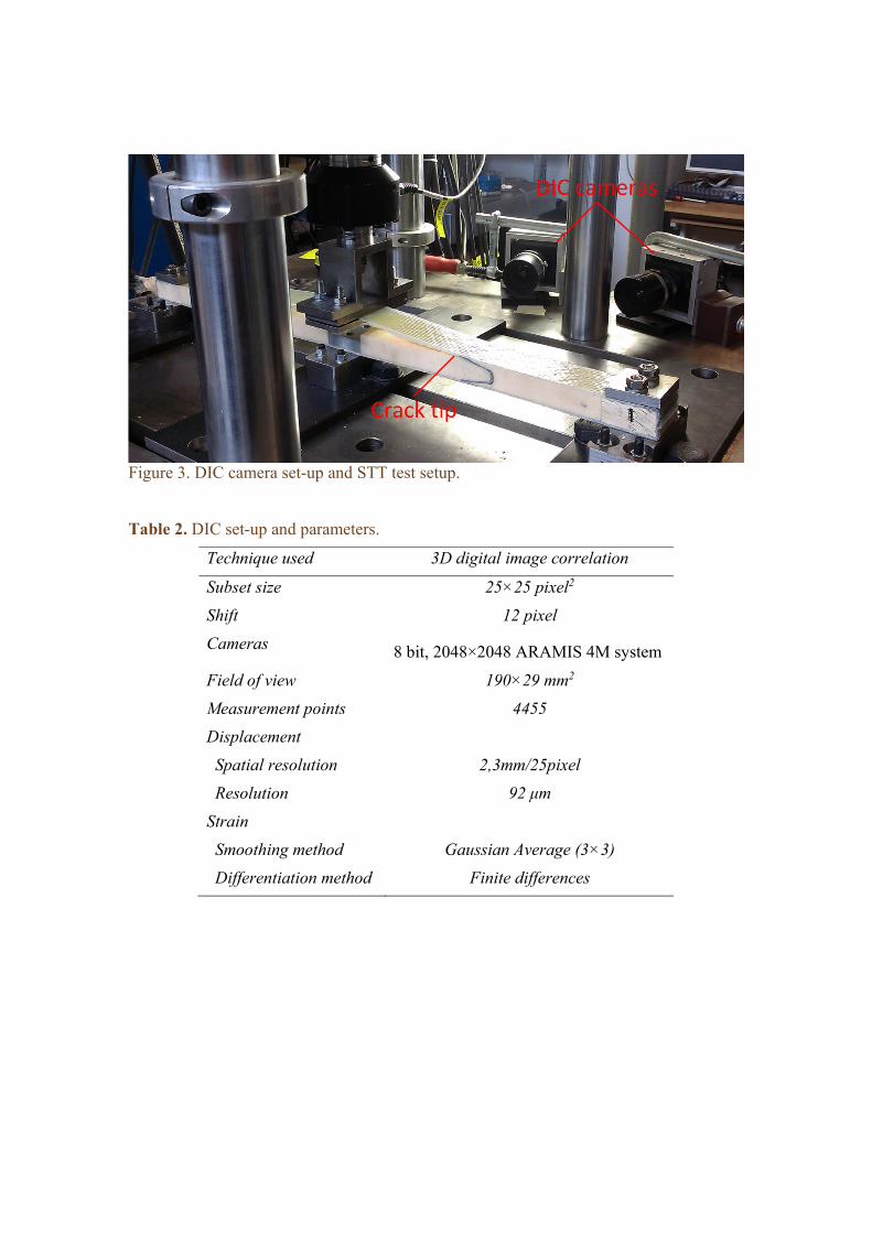
Figure 3. DIC camera set-up and STT test setup.
Table 2. DIC set-up and parameters.
Technique used 3D digital image correlation
Subset size 25×25 pixel2
Shift 12 pixel
Cameras 8 bit, 2048×2048 ARAMIS 4M system
Field of view 190×29 mm2
Measurement points 4455
Displacement
Spatial resolution 2,3mm/25pixel
Resolution 92 μm
Strain
Smoothing method Gaussian Average (3×3)
Differentiation method Finite differences
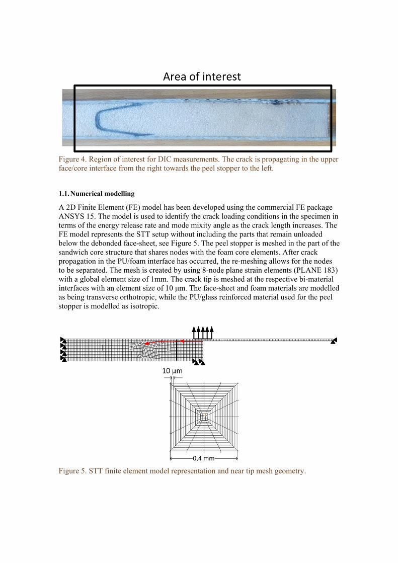
Figure 4. Region of interest for DIC measurements. The crack is propagating in the upper face/core interface from the right towards the peel stopper to the left.
1.1. Numerical modelling
A 2D Finite Element (FE) model has been developed using the commercial FE package ANSYS 15. The model is used to identify the crack loading conditions in the specimen in terms of the energy release rate and mode mixity angle as the crack length increases. The FE model represents the STT setup without including the parts that remain unloaded below the debonded face-sheet, see Figure 5. The peel stopper is meshed in the part of the sandwich core structure that shares nodes with the foam core elements. After crack propagation in the PU/foam interface has occurred, the re-meshing allows for the nodes to be separated. The mesh is created by using 8-node plane strain elements (PLANE 183) with a global element size of 1mm. The crack tip is meshed at the respective bi-material interfaces with an element size of 10 μm. The face-sheet and foam materials are modelled as being transverse orthotropic, while the PU/glass reinforced material used for the peel stopper is modelled as isotropic.
Figure 5. STT finite element model representation and near tip mesh geometry.
The CSDE method [14] was used to calculate the energy release rate and mode mixity phase angle at the crack tip using the reduced formulation [36] defined as:
arctan ( 1 )
| |
4cosh ( 2 )
where G represents the energy release rate and ψ the mode mixity angle of the crack tip. K is the complex form of the stress intensity factor, ε is the oscillation index, while H11 is an anisotropy parameter introduced by Suo [9]. Finally h is a characteristic length here equal to the facesheet thickness.
The CSDE method has been shown to perform well in bi-material interface problems avoiding the oscillating part of the singularities at the near crack tip region [12]. The FE model is used to develop a thorough understanding of the crack propagation behaviour in the STT setup and the conditions under which the crack is deflected and arrested by the peel stopper. This will prove useful when the effect of the peel stopper on the fatigue life of the sandwich specimen is evaluated.
STT TESTING
Identification of test specimen response and crack propagation behaviour
Quasi-static tests were conducted prior to the fatigue tests to identify the load/displacement curves as the crack increases in length. In total, three specimens were tested quasi-statically in displacement control at a rate of 1 mm/min. Figure 6 shows the load-displacement curves for the three STT specimens that were loaded quasi-statically. The face/core interface crack propagated just below the resin rich layer of the core below the face-sheet.
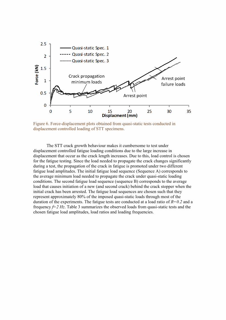
Figure 6. Force-displacement plots obtained from quasi-static tests conducted in displacement controlled loading of STT specimens.
The STT crack growth behaviour makes it cumbersome to test under displacement controlled fatigue loading conditions due to the large increase in displacement that occur as the crack length increases. Due to this, load control is chosen for the fatigue testing. Since the load needed to propagate the crack changes significantly during a test, the propagation of the crack in fatigue is promoted under two different fatigue load amplitudes. The initial fatigue load sequence (Sequence A) corresponds to the average minimum load needed to propagate the crack under quasi-static loading conditions. The second fatigue load sequence (sequence B) corresponds to the average load that causes initiation of a new (and second crack) behind the crack stopper when the initial crack has been arrested. The fatigue load sequences are chosen such that they represent approximately 80% of the imposed quasi-static loads through most of the duration of the experiments. The fatigue tests are conducted at a load ratio of R=0.2 and a frequency f=2 Hz. Table 3 summarizes the observed loads from quasi-static tests and the chosen fatigue load amplitudes, load ratios and loading frequencies.
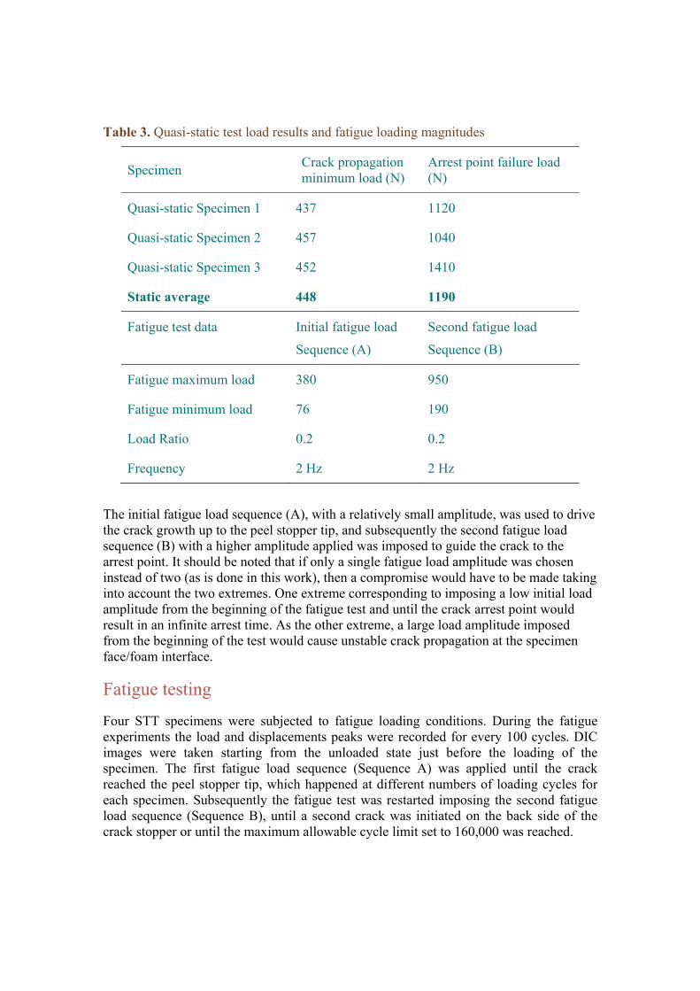
Table 3. Quasi-static test load results and fatigue loading magnitudes
Specimen Crack propagation minimum load (N)
Arrest point failure load (N)
Quasi-static Specimen 1 437 1120
Quasi-static Specimen 2 457 1040
Quasi-static Specimen 3 452 1410
Static average 448 1190
Fatigue test data Initial fatigue load
Sequence (A)
Second fatigue load
Sequence (B)
Fatigue maximum load 380 950
Fatigue minimum load 76 190
Load Ratio 0.2 0.2
Frequency 2 Hz 2 Hz
The initial fatigue load sequence (A), with a relatively small amplitude, was used to drive the crack growth up to the peel stopper tip, and subsequently the second fatigue load sequence (B) with a higher amplitude applied was imposed to guide the crack to the arrest point. It should be noted that if only a single fatigue load amplitude was chosen instead of two (as is done in this work), then a compromise would have to be made taking into account the two extremes. One extreme corresponding to imposing a low initial load amplitude from the beginning of the fatigue test and until the crack arrest point would result in an infinite arrest time. As the other extreme, a large load amplitude imposed from the beginning of the test would cause unstable crack propagation at the specimen face/foam interface.
Fatigue testing
Four STT specimens were subjected to fatigue loading conditions. During the fatigue experiments the load and displacements peaks were recorded for every 100 cycles. DIC images were taken starting from the unloaded state just before the loading of the specimen. The first fatigue load sequence (Sequence A) was applied until the crack reached the peel stopper tip, which happened at different numbers of loading cycles for each specimen. Subsequently the fatigue test was restarted imposing the second fatigue load sequence (Sequence B), until a second crack was initiated on the back side of the crack stopper or until the maximum allowable cycle limit set to 160,000 was reached.
Energy release rate and mode mixity vs. number of cycles
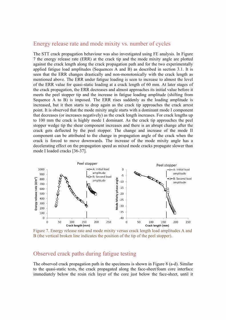
The STT crack propagation behaviour was also investigated using FE analysis. In Figure 7 the energy release rate (ERR) at the crack tip and the mode mixity angle are plotted against the crack length along the crack propagation path and for the two experimentally applied fatigue load amplitudes (Sequences A and B) as described in section 3.1. It is seen that the ERR changes drastically and non-monotonically with the crack length as mentioned above. The ERR under fatigue loading is seen to increase to almost the level of the ERR value for quasi-static loading at a crack length of 60 mm. At later stages of the crack propagation, the ERR decreases and almost approaches its initial value before it meets the peel stopper tip and the increase in fatigue loading amplitude (shifting from Sequence A to B) is imposed. The ERR rises suddenly as the loading amplitude is increased, but it then starts to drop again as the crack tip approaches the crack arrest point. It is observed that the mode mixity angle starts with a dominant mode I component that decreases (or increases negatively) as the crack length increases. For crack lengths up to 100 mm the crack is highly mode I dominant. As the crack tip approaches the peel stopper wedge tip the shear component increases and there is an abrupt change after the crack gets deflected by the peel stopper. The change and increase of the mode II component can be attributed to the change in propagation angle of the crack when the crack is forced to move downwards. The increase of the mode mixity angle has a decelerating effect on the propagation speed as mixed mode cracks propagate slower than mode I loaded cracks [36-37].
Figure 7. Energy release rate and mode mixity versus crack length load amplitudes A and B (the vertical broken line indicates the position of the tip of the peel stopper).
Observed crack paths during fatigue testing
The observed crack propagation path in the specimens is shown in Figure 8 (a-d). Similar to the quasi-static tests, the crack propagated along the face-sheet/foam core interface immediately below the resin rich layer of the core just below the face-sheet, until it
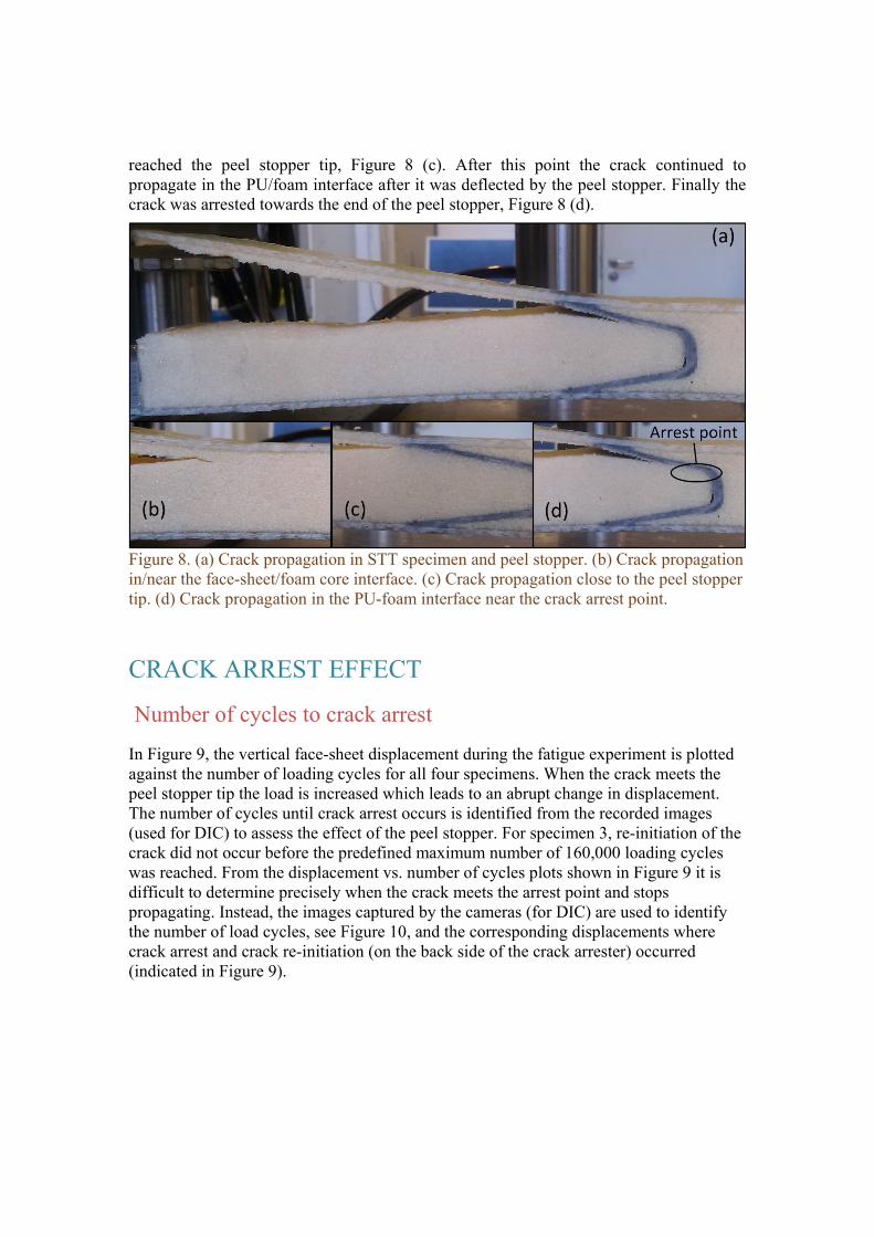
reached the peel stopper tip, Figure 8 (c). After this point the crack continued to propagate in the PU/foam interface after it was deflected by the peel stopper. Finally the crack was arrested towards the end of the peel stopper, Figure 8 (d).
Figure 8. (a) Crack propagation in STT specimen and peel stopper. (b) Crack propagation in/near the face-sheet/foam core interface. (c) Crack propagation close to the peel stopper tip. (d) Crack propagation in the PU-foam interface near the crack arrest point.
CRACK ARREST EFFECT
Number of cycles to crack arrest
In Figure 9, the vertical face-sheet displacement during the fatigue experiment is plotted against the number of loading cycles for all four specimens. When the crack meets the peel stopper tip the load is increased which leads to an abrupt change in displacement. The number of cycles until crack arrest occurs is identified from the recorded images (used for DIC) to assess the effect of the peel stopper. For specimen 3, re-initiation of the crack did not occur before the predefined maximum number of 160,000 loading cycles was reached. From the displacement vs. number of cycles plots shown in Figure 9 it is difficult to determine precisely when the crack meets the arrest point and stops propagating. Instead, the images captured by the cameras (for DIC) are used to identify the number of load cycles, see Figure 10, and the corresponding displacements where crack arrest and crack re-initiation (on the back side of the crack arrester) occurred (indicated in Figure 9).
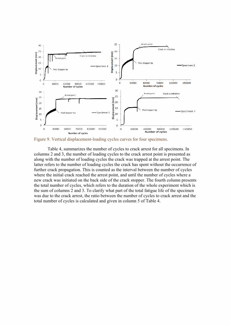
Figure 9. Vertical displacement-loading cycles curves for four specimens.
Table 4, summarizes the number of cycles to crack arrest for all specimens. In columns 2 and 3, the number of loading cycles to the crack arrest point is presented as along with the number of loading cycles the crack was trapped at the arrest point. The latter refers to the number of loading cycles the crack has spent without the occurrence of further crack propagation. This is counted as the interval between the number of cycles where the initial crack reached the arrest point, and until the number of cycles where a new crack was initiated on the back side of the crack stopper. The fourth column presents the total number of cycles, which refers to the duration of the whole experiment which is the sum of columns 2 and 3. To clarify what part of the total fatigue life of the specimen was due to the crack arrest, the ratio between the number of cycles to crack arrest and the total number of cycles is calculated and given in column 5 of Table 4.
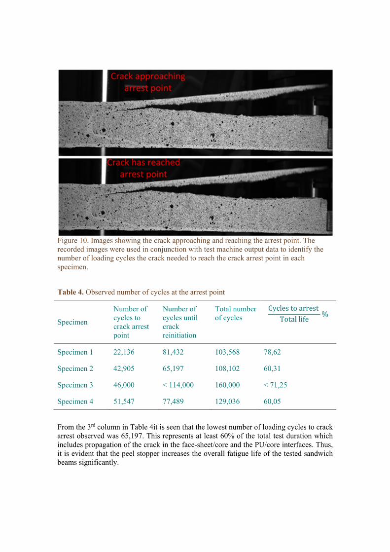
Figure 10. Images showing the crack approaching and reaching the arrest point. The recorded images were used in conjunction with test machine output data to identify the number of loading cycles the crack needed to reach the crack arrest point in each specimen.
Table 4. Observed number of cycles at the arrest point
Specimen
Number of cycles to crack arrest point
Number of cycles until crack reinitiation
Total number of cycles
CyclestoarrestTotallife
%
Specimen 1 22,136 81,432 103,568 78,62
Specimen 2 42,905 65,197 108,102 60,31
Specimen 3 46,000 < 114,000 160,000 < 71,25
Specimen 4 51,547 77,489 129,036 60,05
From the 3rd column in Table 4it is seen that the lowest number of loading cycles to crack arrest observed was 65,197. This represents at least 60% of the total test duration which includes propagation of the crack in the face-sheet/core and the PU/core interfaces. Thus, it is evident that the peel stopper increases the overall fatigue life of the tested sandwich beams significantly.
Moreover, Figure 7 shows that the crack energy release rate at the crack arrest point is significant. This demonstrates that the crack would be free to propagate at a comparatively high rate if the peel stopper was not present. The increased mode II component of the crack due to its change of direction (when crack deflection along the PU/core interface occurs when load sequence B is imposed) also has a significant effect on the crack propagation speed.
Strain distribution from DIC
The failure mechanisms that drive crack re-initiation can be identified using DIC to capture the strain fields on the surfaces of the tested specimens. In Figure 11, the major principal strain field is plotted for all four specimens at the loads and number of cycles corresponding to crack arrest after the crack has been deflected away from the face /core interface. It is observed that a strain concentration appears on the back side of the crack arrester corresponding to the arrest point in the core material. It is hypothesized that this strain concentration (which is linked to a corresponding stress concentration) is causing the initiation of a new crack in the foam core material behind the crack arrester.
From Figure 11 it is further observed that the propagating crack in specimen 4 followed a slightly different path compared to the rest of the specimens. The crack kinked from the upper face-sheet/core interface into the foam, where it reached the lower interface and then kinked back to the upper interface to continue the propagation there. This behaviour may be attributed to the high mode I dominance in the mode mixity for small crack lengths, see Figure 7. Under mode I dominated loading conditions the crack may kink prematurely away from the initial path in any direction, due to the strongly heterogeneous nature of the foam core cell morphology, and even though positive mode II conditions do not occur. Opposed to this, the crack always propagates towards the upper face-sheet where it stays in the region of the face /core or PU/core interfaces when the crack experiences increased negative mode II component loading.
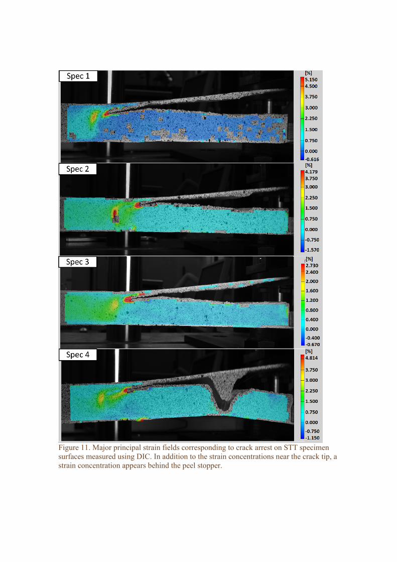
Figure 11. Major principal strain fields corresponding to crack arrest on STT specimen surfaces measured using DIC. In addition to the strain concentrations near the crack tip, a strain concentration appears behind the peel stopper.
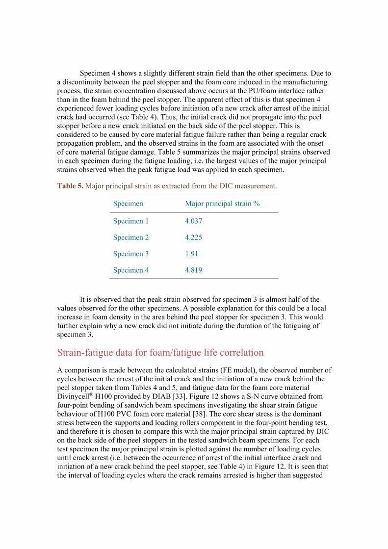
Specimen 4 shows a slightly different strain field than the other specimens. Due to a discontinuity between the peel stopper and the foam core induced in the manufacturing process, the strain concentration discussed above occurs at the PU/foam interface rather than in the foam behind the peel stopper. The apparent effect of this is that specimen 4 experienced fewer loading cycles before initiation of a new crack after arrest of the initial crack had occurred (see Table 4). Thus, the initial crack did not propagate into the peel stopper before a new crack initiated on the back side of the peel stopper. This is considered to be caused by core material fatigue failure rather than being a regular crack propagation problem, and the observed strains in the foam are associated with the onset of core material fatigue damage. Table 5 summarizes the major principal strains observed in each specimen during the fatigue loading, i.e. the largest values of the major principal strains observed when the peak fatigue load was applied to each specimen.
Table 5. Major principal strain as extracted from the DIC measurement.
Specimen Major principal strain %
Specimen 1 4.037
Specimen 2 4.225
Specimen 3 1.91
Specimen 4 4.819
It is observed that the peak strain observed for specimen 3 is almost half of the values observed for the other specimens. A possible explanation for this could be a local increase in foam density in the area behind the peel stopper for specimen 3. This would further explain why a new crack did not initiate during the duration of the fatiguing of specimen 3.
Strain-fatigue data for foam/fatigue life correlation
A comparison is made between the calculated strains (FE model), the observed number of cycles between the arrest of the initial crack and the initiation of a new crack behind the peel stopper taken from Tables 4 and 5, and fatigue data for the foam core material Divinycell® H100 provided by DIAB [33]. Figure 12 shows a S-N curve obtained from four-point bending of sandwich beam specimens investigating the shear strain fatigue behaviour of H100 PVC foam core material [38]. The core shear stress is the dominant stress between the supports and loading rollers component in the four-point bending test, and therefore it is chosen to compare this with the major principal strain captured by DIC on the back side of the peel stoppers in the tested sandwich beam specimens. For each test specimen the major principal strain is plotted against the number of loading cycles until crack arrest (i.e. between the occurrence of arrest of the initial interface crack and initiation of a new crack behind the peel stopper, see Table 4) in Figure 12. It is seen that the interval of loading cycles where the crack remains arrested is higher than suggested
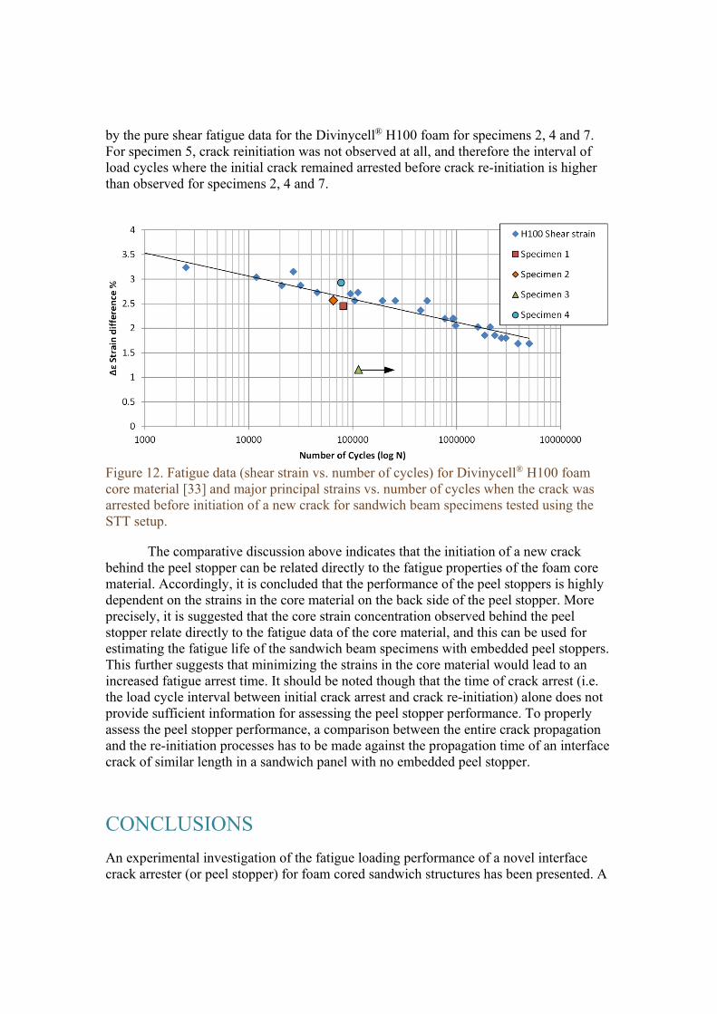
by the pure shear fatigue data for the Divinycell® H100 foam for specimens 2, 4 and 7. For specimen 5, crack reinitiation was not observed at all, and therefore the interval of load cycles where the initial crack remained arrested before crack re-initiation is higher than observed for specimens 2, 4 and 7.
Figure 12. Fatigue data (shear strain vs. number of cycles) for Divinycell® H100 foam core material [33] and major principal strains vs. number of cycles when the crack was arrested before initiation of a new crack for sandwich beam specimens tested using the STT setup.
Τhe comparative discussion above indicates that the initiation of a new crack behind the peel stopper can be related directly to the fatigue properties of the foam core material. Accordingly, it is concluded that the performance of the peel stoppers is highly dependent on the strains in the core material on the back side of the peel stopper. More precisely, it is suggested that the core strain concentration observed behind the peel stopper relate directly to the fatigue data of the core material, and this can be used for estimating the fatigue life of the sandwich beam specimens with embedded peel stoppers. This further suggests that minimizing the strains in the core material would lead to an increased fatigue arrest time. It should be noted though that the time of crack arrest (i.e. the load cycle interval between initial crack arrest and crack re-initiation) alone does not provide sufficient information for assessing the peel stopper performance. To properly assess the peel stopper performance, a comparison between the entire crack propagation and the re-initiation processes has to be made against the propagation time of an interface crack of similar length in a sandwich panel with no embedded peel stopper.
CONCLUSIONS
An experimental investigation of the fatigue loading performance of a novel interface crack arrester (or peel stopper) for foam cored sandwich structures has been presented. A
PVC foam cored and GFRP composite face-sandwich specimen configuration with embedded peel stoppers was chosen for the investigation. In this configuration the energy release rate and mode mixity of the crack vary considerably with the crack length. The Sandwich Tear Test (STT) together with DIC was used to evaluate the crack arrest effect of the peel stopper as well as the identification of the mechanisms of crack reinitiation behind the peel stopper.
The new peel stopper was found to perform well under fatigue loading conditions. The observed crack propagation paths can be divided into 3 phases: (1) Firstly the propagating initial face-sheet/core interface crack was deflected away from the face-sheet/core interface when reaching the peel stopper tip; (2) the crack was arrested inside the peel stopper and remained arrested for than 67% of the total duration of the fatigue experiments; (3) finally a new crack was initiated in the core material behind the peel stopper. An investigation of the strain distribution in the vicinity of the crack arrest area suggests that the post-crack arrest behaviour was determined by the fatigue properties of the foam core material used in the sandwich panels. This further suggests that the effectiveness and overall performance of the peel stopper are highly dependent on the local strains developed in the core material on the back side of the peel stopper behind the arrest point.
ACKNOWLEDGEMENTS The work was sponsored by the Danish Council for Independent Research | Technology & Production Sciences (FTP) under the research grant “Enhanced performance of sandwich structures by improved damage tolerance" (SANTOL) (Grant 10082020). The Divinycell H100 material used in this study was provided by DIAB Group, Sweden. The work has been conducted in collaboration with and co-sponsored by the Technical University of Denmark, Aalborg University, Denmark, the University of Southampton, UK, Siemens Wind Power A/S, Denmark, and LM Wind Power Blades A/S, Denmark.
REFERENCES
[1] Zenkert, D., “An introduction to sandwich construction” London: Chameleon Press Ltd, 1995
[2] Jakobsen, J., Bozhevolnaya, E., Thomsen, O.T., 2007. New peel stopper concept for sandwich structures. Compos Sci Technol. 67:3378–85.
[3] Jakobsen, J., Andreasen, J.H., Bozhevolnaya, E., 2008. Crack kinking of a delamination at an inclined core junction interface in a sandwich beam. Eng Fract Mech. 75(16):4759–73.
[4] Wang, W., Martakos, G., Dulieu-Barton, J. M., Andreasen, J. H., Thomsen, O. T., 2015. Fracture behaviour at tri-material junctions of crack stoppers in sandwich structures. Composite Structures 133, 818-833
[5] Erdogan, F., 1971. Bonded dissimilar materials containing cracks parallel to the interface, Engineering Fracture Mechanics, 3(3), 231-240.
[6] Dundurs, J. Edge-bonded dissimilar orthogonal elastic wedges. J.Appl.Mech. 36. 650-652.(1969)
[7] Hutchinson, J.W., Suo, Z., 1992 . Mixed Mode Cracking in Layered Materials, Advances in Applied Mechanics, 29, 63-191.
[8] He, M.., Hutchinson, JW. 1989. Kinking of a Crack Out of an Interface. ASME. J. Appl. Mech.;56(2):270-278
[9] Suo, Z., 1990. Singularities, interfaces and cracks in dissimilar anisotropic media. Proceedings of the Royal Society of London A: Mathematical, Physical and Engineering Sciences 427 (1873), 331-358.
[10] Wang, T. C., 1994. Kinking of an interface crack between two dissimilar anisotropic elastic solids. International Journal of Solids and Structures 31 (5), 629–641.
[11] Zenkert, D., 1991. Strength of sandwich beams with interface debondings. Composite Structures 17 (4), 331–350.
[12] Berggreen, C., 2004. Damage tolerance in debonded sandwich structures. PhD. Thesis. Department of Mechanical Engineering, Technical University of Denmark.
[13] Moslemian, R., Karlsson, A. M., Berggreen, C., 2011. Accelerated fatigue crack growth simulation in a bimaterial interface. International Journal of Fatigue 33 (12), 1526–1532.
[14] Berggreen, C., Simonsen, B. C., Borum, K. K., Feb. 2007. Experimental and numerical study of interface crack propagation in foam-cored sandwich beams. Journal of Composite Materials 41 (4), 493–520.
[15] Berggreen, C., Simonsen, B. C., 2005. Non-uniform compressive strength of debonded sandwich panels – II. Fracture mechanics investigation. Journal of Sandwich Structures and Materials 7 (6), 483-517.
[16] Moslemian, R., Berggreen, C., Jul. 2013. Interface fatigue crack propagation in sandwich x-joints – part II: Finite element modeling. Journal of Sandwich Structures and Materials 15 (4), 451-463
[17] Prasad, S., Carlsson, L. A., 1994. Debonding and crack kinking in foam core sandwich beams—I. analysis of fracture specimens. Engineering Fracture Mechanics 47 (6), 813–824.
[18] Prasad, S., Carls8son, L. A., 1994. Debonding and crack kinking in foam core sandwich beams—II. experimental investigation. Engineering Fracture Mechanics 47 (6), 825–841.
[19] Carlsson, L.A., Sendlein, L.S. and Merry, S.L., 2004. Characterization of face sheet/core shear fracture of composite sandwich beams. J Compos Mater, 25: 101–116.
[20] Quispitupa, A., Berggreen, C., Carlsson, L. A., 2009. On the analysis of a mixed mode bending sandwich specimen for debond fracture characterization. Engineering Fracture Mechanics 76 (4), 594–613.
[21] Manca, M., Quispitupa, A., Berggreen, C., Carlsson, L. A., 2012. Face/core debond fatigue crack growth characterization using the sandwich mixed mode bending specimen. Composites Part A: Applied Science and Manufacturing 43 (11), 2120–2127.
[22] Manca, M., Berggreen, C., Carlsson, L. A., 2015. G-control fatigue testing for cyclic crack propagation in composite structures. Engineering Fracture Mechanics.
[23] Rinker, M., Zahlen, P. C., John, M., Schäuble, R., 2012. Investigation of sandwich crack stop elements under fatigue loading. Journal of Sandwich Structures and Materials 14 (1), 55–73.
[24] Hirose, Y., Matsubara, G., Hojo, M., Matsuda, H., Inamura, F., 2008. Evaluation of modified crack arrester by fracture toughness tests under mode I type and mode II type loading for foam core sandwich panel. In: Proc. US-Japan conference on composite materials 2008, Tokyo, Japan.
[25] Hirose, Y., Matsuda, H., Matsubara, G., Hojo, M., Inamura, F., 2012. Proposal of the concept of splice-type arrester for foam core sandwich panels. Composites Part A: Applied Science and Manufacturing 43 (8), 1318–1325.
[26] Johannes, M., Jakobsen, J., Thomsen, O. T., Bozhevolnaya, E., 2009. Examination of the failure of sandwich beams with core junctions subjected to in-plane tensile loading. Composites Science and Technology 69 (9), 1447-1457.
[27] Johannes, M., Thomsen, O. T., 2010. Examination of the failure of sandwich beams with core junctions subjected to transverse shear loading. Journal of Sandwich Structures and Materials 12 (2), 199–236.
[28] Bozhevolnaya, E., Jakobsen, J., Thomsen, O.T., 2009. Performance of sandwich panels with peel stoppers, strain. Int J Exp Mech 45. 349–57.
[29] Bozhevolnaya, E., Jakobsen, J., Thomsen, O.T., 2009. Fatigue Performance of Sandwich Beams With Peel Stoppers, Strain, 45(4) 349-357.
[30] Jakobsen, J., Thomsen, O.T., Andreasen, J.H., Bozhevolnaya, E., 2009. Crack deflection analyses of different peel stopper design for sandwich structure. Compos SciTechnol 69:870–5.
[31] Jakobsen, J., Andreasen, J.H., Thomsen, O.T., 2009. Crack deflection by core junctions in sandwich structures. Eng Fract Mech. 76(14):2135–47.
[32] Jakobsen, J., 2004. Local Effects and the Control of Face-Core Debond Failure in Sandwich Structures . PhD. Thesis. Department of Mechanical Engineering, Aalborg University.
[33] DIAB. Divinycell H-Grade Technical data, 2014. Laholm (Sweeden) (http://www.diabgroup.com).
[34] Moslemian, R., 2011. Residual Strength and Fatigue lifetime of debonded damaged sandwich structures. PhD. Thesis. Department of Mechanical Engineering, Technical University of Denmark; September.
[35] Taher, S.T., Thomsen, O.T., Dulieu-Barton, J.M. and Zhang, S., 2011. Determination of mechanical properties of PVC foam using a modified Arcan fixture. Composites Part A: Applied Science and Manufacturing, 43, 1678-1708. (doi:10.1016/j.compositesa.2011.11.010).

[36] Berggreen, C., Carlsson, L. A., 2010. A modified TSD specimen for fracture toughness characterization - fracture mechanics analysis and design. Journal of Composite Materials 44 (15), 1893-1912.
[37] Shipsha, A., Burman, M., Zenkert, D., 1999. Interfacial fatigue crack growth in foam core sandwich structures. Fatigue & Fracture of Engineering Materials & Structures 22 (2), 123–131.
[38] Burman, M., Magnusson, B., 2008. Fatigue testing of H60, H100 and H200. Technical report (DIAB), KTH (Sweeden).


![Kaj Thomsen 1[1].pdf](https://static.fdocuments.in/doc/165x107/55cf97ca550346d03393a2b3/kaj-thomsen-11pdf.jpg)