Experimental Investigation for Damping Vibration using...
7
International Journal of Current Engineering and Technology E-ISSN 2277 – 4106, P-ISSN 2347 – 5161 ©2016 INPRESSCO ® , All Rights Reserved Available at http://inpressco.com/category/ijcet Research Article 1189| International Journal of Current Engineering and Technology, Vol.6, No.4 (Aug 2016) Experimental Investigation for Damping Vibration using Secondary Bed Material B.Nagaraju †* , P.Hussain † and A.Ramanjaneya Reddy † † AVR and SVR College of Engineering and Technology, Kurnool, Andhra Pradesh, India Accepted 10 July 2016, Available online 15 July 2016, Vol.6, No.4 (Aug 2016) Abstract Unwanted vibration in machine tools like milling, lathe, grinding machine is one of the main problem as it affects the quality of the machined parts, tool life and noise during machining operation. Hence these unwanted vibrations are needed to be suppressed or damped out while machining. Therefore the present work concentrates and aims on study of different controllable parameter that affect the responses like vibration amplitude and roughness of machined part. The part to be machined is kept on sandwich of plates made up of polymer and composite material. The sandwich along with the part to be machined is fixed on the slotted table of horizontal milling machine. Finite element analysis (FEA) was carried out to know the resonance frequencies at which the structure should not be excited. Keywords: vibration, amplitude, polymer, composite. 1. Introduction 1 Vibration is a mechanical phenomenon whereby oscillations occur by an equilibrium point. The oscillations may be periodic, such as the motion of a pendulum or random, such as the movement of a tire on a gravel road. Vibration can be desirable: for example, the motion of a tuning fork, the reed in a woodwind instrument or harmonica, a mobile phone, or the cone of a loudspeaker. In many cases, however, vibration is undesirable, wasting energy and creating unwanted sound. For example, the vibration motions of engines, electric motors, or any mechanical device in operation are typically unwanted. Such vibrations could be caused by imbalances in the rotating parts, uneven friction, or the meshing of gear teeth. Careful designs usually minimize unwanted vibrations. Machining of any kind is accompanied by vibrations of work-piece and tool. These vibrations occur due to the following reasons. 1) In-homogeneities in the work piece material 2) Variation of chip cross section 3) Disturbances in the work piece 4) Dynamic loads generated by acceleration of massive moving components 5) Vibration transmitted from the environment. 6) Self-excited vibration generated by the cutting. *Corresponding author B.Nagaraju is a M.Tech Scholar; P.Hussain is working as Associate Professor and A.Ramanjaneya Reddy as Assistant Professor Due to these vibrations the following phenomenon occurs. 1) Reduction in tool life. 2) Improper surface quality. 3) Undesirable Noise. 4) Excessive load on machine tool. This phenomenon can be reduced when machine tools have high stiffness. High stiffness in machine tools can be achieved by making them by robust structured materials through passive damping technology. 2. Vibration overview Dynamic responses of a structure can be determined by three essential parameters. 1) Mass 2) Stiffness 3) Damping Storage of energy is associated with mass and stiffness whereas damping results in the dissipation of energy by a vibration of a system. For a linear system, if the forcing frequency is the same as the natural frequency of the system, the response is very large and can easily cause dangerous consequences due to resonance effect. In the frequency domain, the response near the natural frequency is damping controlled. 2.1 Damping Damping is a phenomenon by which mechanical
Transcript of Experimental Investigation for Damping Vibration using...
International Journal of Current Engineering and Technology E-ISSN 2277 – 4106, P-ISSN 2347 – 5161 ©2016 INPRESSCO®, All Rights Reserved Available at http://inpressco.com/category/ijcet
Research Article
1189| International Journal of Current Engineering and Technology, Vol.6, No.4 (Aug 2016)
Experimental Investigation for Damping Vibration using Secondary Bed Material
B.Nagaraju†*, P.Hussain† and A.Ramanjaneya Reddy†
†AVR and SVR College of Engineering and Technology, Kurnool, Andhra Pradesh, India Accepted 10 July 2016, Available online 15 July 2016, Vol.6, No.4 (Aug 2016)
Abstract Unwanted vibration in machine tools like milling, lathe, grinding machine is one of the main problem as it affects the quality of the machined parts, tool life and noise during machining operation. Hence these unwanted vibrations are needed to be suppressed or damped out while machining. Therefore the present work concentrates and aims on study of different controllable parameter that affect the responses like vibration amplitude and roughness of machined part. The part to be machined is kept on sandwich of plates made up of polymer and composite material. The sandwich along with the part to be machined is fixed on the slotted table of horizontal milling machine. Finite element analysis (FEA) was carried out to know the resonance frequencies at which the structure should not be excited. Keywords: vibration, amplitude, polymer, composite. 1. Introduction
1 Vibration is a mechanical phenomenon whereby oscillations occur by an equilibrium point. The oscillations may be periodic, such as the motion of a pendulum or random, such as the movement of a tire on a gravel road. Vibration can be desirable: for example, the motion of a tuning fork, the reed in a woodwind instrument or harmonica, a mobile phone, or the cone of a loudspeaker. In many cases, however, vibration is undesirable, wasting energy and creating unwanted sound. For example, the vibration motions of engines, electric motors, or any mechanical device in operation are typically unwanted. Such vibrations could be caused by imbalances in the rotating parts, uneven friction, or the meshing of gear teeth. Careful designs usually minimize unwanted vibrations. Machining of any kind is accompanied by vibrations of work-piece and tool. These vibrations occur due to the following reasons. 1) In-homogeneities in the work piece material 2) Variation of chip cross section 3) Disturbances in the work piece 4) Dynamic loads generated by acceleration of
massive moving components 5) Vibration transmitted from the environment. 6) Self-excited vibration generated by the cutting.
*Corresponding author B.Nagaraju is a M.Tech Scholar; P.Hussain is working as Associate Professor and A.Ramanjaneya Reddy as Assistant Professor
Due to these vibrations the following phenomenon occurs.
1) Reduction in tool life. 2) Improper surface quality. 3) Undesirable Noise. 4) Excessive load on machine tool.
This phenomenon can be reduced when machine tools have high stiffness. High stiffness in machine tools can be achieved by making them by robust structured materials through passive damping technology. 2. Vibration overview
Dynamic responses of a structure can be determined by three essential parameters.
1) Mass 2) Stiffness 3) Damping Storage of energy is associated with mass and stiffness whereas damping results in the dissipation of energy by a vibration of a system. For a linear system, if the forcing frequency is the same as the natural frequency of the system, the response is very large and can easily cause dangerous consequences due to resonance effect. In the frequency domain, the response near the natural frequency is damping controlled. 2.1 Damping Damping is a phenomenon by which mechanical
Nagaraju et al Experimental Investigation for Damping Vibration Using Secondary Bed Material
1190| International Journal of Current Engineering and Technology, Vol.6, No.4 (Aug 2016)
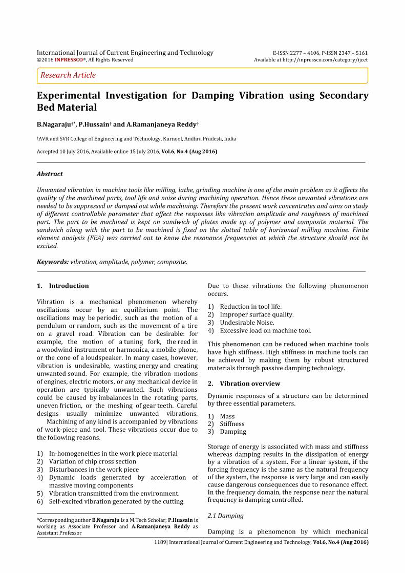
energy is dissipated in dynamic systems. In other words it is also said to be any effect that tends to reduce the amplitude of vibration in an oscillatory system. For a spring mass damper system, the equation of motion is represented by mẍ+Cẋ+kx=0 Where m in (kg) is the mass of the system, k is the spring constant (in N/m), c is the damping coefficient in (Ns/m or Kg/ Sec).
Fig.1 Spring mass damper system
2.2 Vibration in machine tools The Machine, cutting tool, and work piece together form a structural system which has complicated dynamic characteristics. Vibrations of the structural system, vibrations may be divided into three basic types. 2.2.1 Free or Transient vibrations: Impulses transferred through machine foundation to the structure, from fast traversals of reciprocating masses like machine tables, or impulses transferred by the initial engagement of cutting tools cause free vibration. The structure is deflected and oscillates naturally until the damping present in the structure causes the motion to diminish to zero. 2.2.2 Forced vibration: Forced vibration is said to be occurred by a periodic forces applied to system, like unbalanced rotating masses or the irregular engagement of multi-tooth cutters (in this case milling), or vibration transmitted from nearby machinery through the foundations. The machine tool oscillating at the forcing frequency, and if this frequency matches with to one of the natural frequency or resonant frequency of the structure, the machine will resonate in the corresponding natural mode of vibration.
2.2.3 Self-excited vibrations Dynamic Instability of the cutting process cause Self-excited vibrations. This phenomenon is commonly called machine tool chatter. If large tool-work engagements are given, oscillations build up in the structure. In this case structure oscillates in one of its natural modes of vibration. 2.3 Damping in machine tools Damping in machine tools basically is derived from two sources one is material damping and other is slip damping. The extent of material damping is very small
in comparison to the total damping in machine tools. A typical damping ratio value for material damping in machine tools is in the order of 0.003 which accounts for about 10% of the total damping. The interfacial slip damping outcomes from the contact surfaces at bolted joints and sliding joints which contribute approximately 90% of the total damping. Welded joints usually provide very small damping which may be neglected when considering damping in joints. Whereas sliding joints contribute most of the damping. 3. Main Objective Of The Research Work The main objective of the work is to study The effect of controllable parameter like feed, RPM,
depth of cut and number of layer of secondary bed material on vibration amplitude and surface roughness of machined part.
To find a model equation that represents a relationship between response and controllable parameter that affects the response by the help of Response Surface Methodology (RSM).
3.1 Why to use secondary bed material (SBM) The bed (sandwich of composite) intended to act as
vibration absorbers. Polymers and composite have
been utilized as a bed to the work-piece because of it
excellent damping characteristics. Passive damping
technology has a wide variety of engineering
applications such as follows.
Vibration absorber in Bridges, Engine mounts,
Machine components such as rotating shafts. Component vibration isolation. Novel spring designs which incorporate damping
without the use of traditional dashpots or shock absorbers, and structural supports.
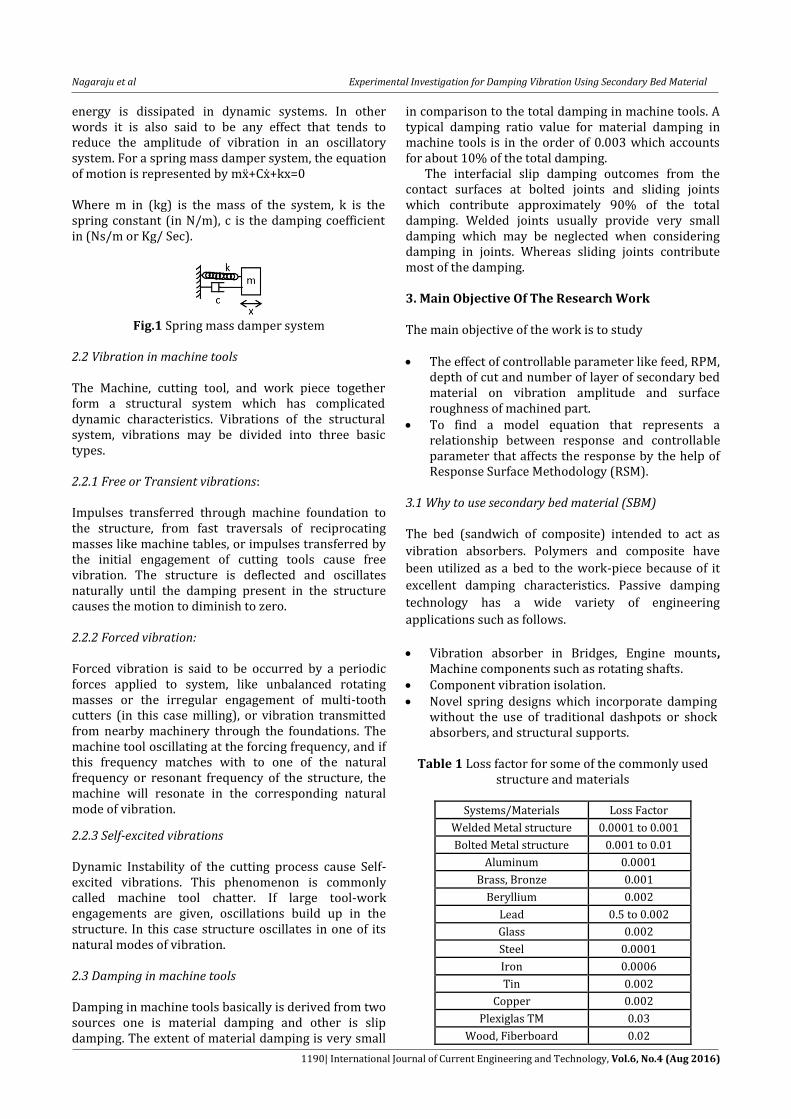
Table 1 Loss factor for some of the commonly used
structure and materials
Systems/Materials Loss Factor
Welded Metal structure 0.0001 to 0.001
Bolted Metal structure 0.001 to 0.01
Aluminum 0.0001
Brass, Bronze 0.001
Beryllium 0.002
Lead 0.5 to 0.002
Glass 0.002
Steel 0.0001
Iron 0.0006
Tin 0.002
Copper 0.002
Plexiglas TM 0.03
Wood, Fiberboard 0.02
Nagaraju et al Experimental Investigation for Damping Vibration Using Secondary Bed Material
1191| International Journal of Current Engineering and Technology, Vol.6, No.4 (Aug 2016)
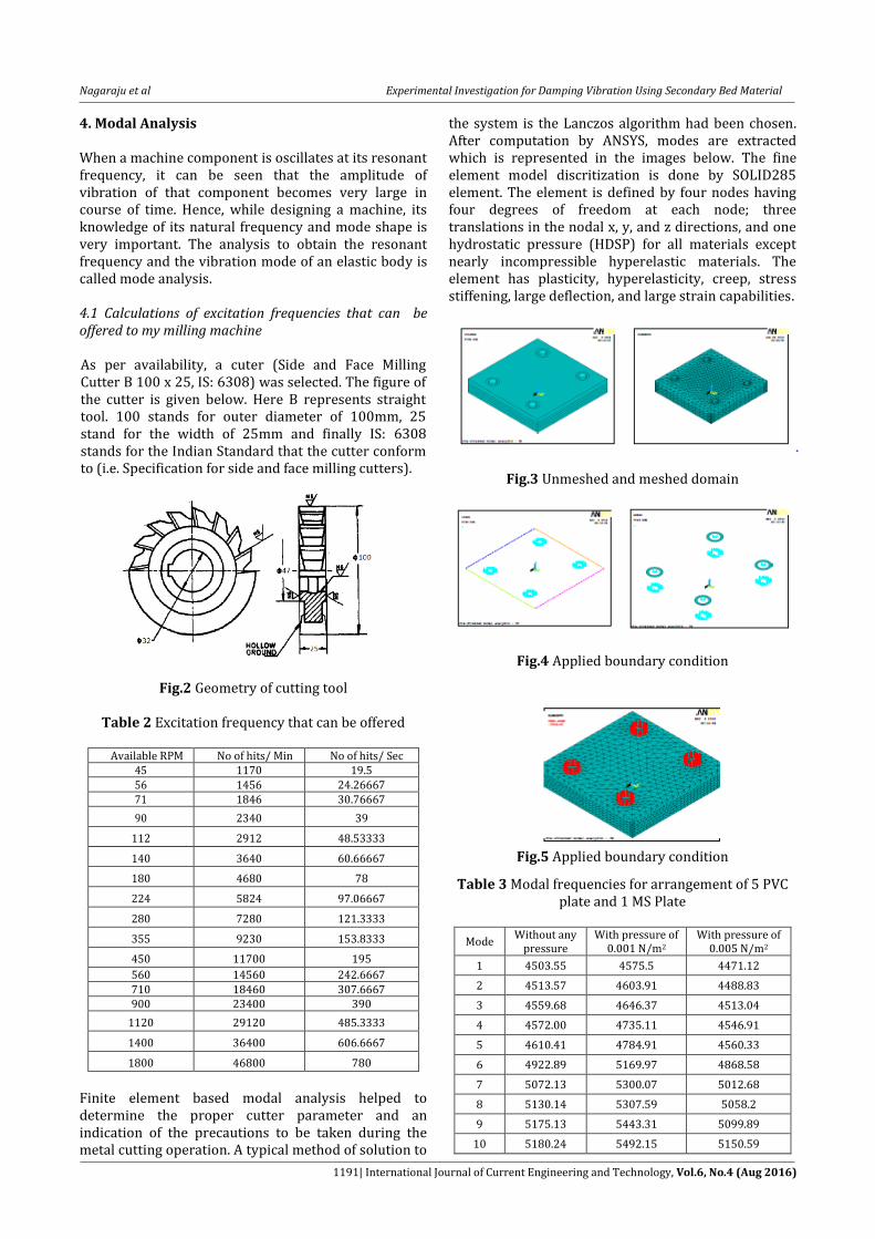
4. Modal Analysis When a machine component is oscillates at its resonant frequency, it can be seen that the amplitude of vibration of that component becomes very large in course of time. Hence, while designing a machine, its knowledge of its natural frequency and mode shape is very important. The analysis to obtain the resonant frequency and the vibration mode of an elastic body is called mode analysis. 4.1 Calculations of excitation frequencies that can be offered to my milling machine As per availability, a cuter (Side and Face Milling Cutter B 100 x 25, IS: 6308) was selected. The figure of the cutter is given below. Here B represents straight tool. 100 stands for outer diameter of 100mm, 25 stand for the width of 25mm and finally IS: 6308 stands for the Indian Standard that the cutter conform to (i.e. Specification for side and face milling cutters).
Fig.2 Geometry of cutting tool
Table 2 Excitation frequency that can be offered
Available RPM No of hits/ Min No of hits/ Sec 45 1170 19.5 56 1456 24.26667 71 1846 30.76667
90 2340 39
112 2912 48.53333
140 3640 60.66667
180 4680 78
224 5824 97.06667
280 7280 121.3333
355 9230 153.8333
450 11700 195
560 14560 242.6667 710 18460 307.6667 900 23400 390
1120 29120 485.3333
1400 36400 606.6667
1800 46800 780
Finite element based modal analysis helped to determine the proper cutter parameter and an indication of the precautions to be taken during the metal cutting operation. A typical method of solution to
the system is the Lanczos algorithm had been chosen. After computation by ANSYS, modes are extracted which is represented in the images below. The fine element model discritization is done by SOLID285 element. The element is defined by four nodes having four degrees of freedom at each node; three translations in the nodal x, y, and z directions, and one hydrostatic pressure (HDSP) for all materials except nearly incompressible hyperelastic materials. The element has plasticity, hyperelasticity, creep, stress stiffening, large deflection, and large strain capabilities.
Fig.3 Unmeshed and meshed domain
Fig.4 Applied boundary condition
Fig.5 Applied boundary condition
Table 3 Modal frequencies for arrangement of 5 PVC plate and 1 MS Plate
Mode Without any
pressure With pressure of
0.001 N/m2 With pressure of
0.005 N/m2
1 4503.55 4575.5 4471.12
2 4513.57 4603.91 4488.83
3 4559.68 4646.37 4513.04
4 4572.00 4735.11 4546.91
5 4610.41 4784.91 4560.33
6 4922.89 5169.97 4868.58
7 5072.13 5300.07 5012.68
8 5130.14 5307.59 5058.2
9 5175.13 5443.31 5099.89
10 5180.24 5492.15 5150.59
Nagaraju et al Experimental Investigation for Damping Vibration Using Secondary Bed Material
1192| International Journal of Current Engineering and Technology, Vol.6, No.4 (Aug 2016)
Table 4 Mechanical properties of PVC used for simulation
Density g/cm3 1.4
Youngs modulus E (GPa) 1.5
Shear modulus G (GPa) 0.6
Poisons ratio 0.42
Yield stress (MPa) 53
UTS (MPa) 60
Breaking strain % 50
Thermal expansion 10-6/C 75
5. Experimental Investigation
The design of experiments technique being a very
powerful tool, helped in modelling and analysing the
effect of process variables on the response variables.
The response variable (or parameter of interest) is an
unknown function of the process variables (or
controllable parameters or as design factors).
5.1 Design of experiment
The following four machining parameters have been
used to control the milling process: depth of cut (d,
mm), spindle speed (s, rpm) and feed rate (f, mm/min)
and finally the number of secondary bed material used
to form the sandwich on which the material to be
machined (MS plate) was placed. In the present
investigation these four parameters were selected as
design factors while other parameter like tightening
pressure have been kept constant over the
experimental domain.
Table 5 Level setting for experiment
No of Layers of secondary bed material ‘No’
Cutter Speed ‘s’ (in RPM)
Depth of cut ‘d’ (in
mm)
Feed Rate ‘f’ (in mm/Min)
1 180 0.01 16
3 224 0.02 20
5 280 0.03 25
5.2 Equipment used The machine used for the milling tests was a Horizontal
Milling Machine (HMT FN2U) with maximum spindle
speed of 1800 rpm, feed rate 800 m/min and 5.5 kW
driver motor.
5.3 Cutting tools used As per availability, a cuter (Side and Face Milling Cutter
B 100 x 25, IS: 6308) was selected. The figure of the
cutter is given below. Here B represents straight tool.
100 stands for outer diameter of 100mm, 25 stand for
the width of 25mm and finally IS: 6308 stands for the
Indian Standard that the cutter conform to (i.e.
Specification for side and face milling cutters). The
cutter has 26 numbers of teeth.
5.4 Work piece materials The present study was carried out with MS Plate. The
chemical composition and mechanical properties of the
work piece materials are as follows. All the specimens
were in the form of 210 mm × 210 mm × 10 mm blocks
with four holes of 20 mm diameter shown below.
5.5 Experimental setup and procedure
The stack of secondary bed material along the work-
piece material was kept on the slotted table of the
milling machine. Bolts were placed in the hole and
tightened by the use of a torque wrench so as to keep
the tightening pressure constant. After fixing the work
piece Vibration was placed on the work-piece to get the
vibration signal in the oscilloscope (the other end of
the cord was put to the first input port of the
oscilloscope.).
Fig.6 Experimental setup Then the machining (up milling) was done. After
machining of MS plate the surface roughness was
measured in the Talysurf. Measurements, in the
transverse direction, on the work pieces were repeated
three times and an average measurements value was
recorded. The experiment (measurement of vibration
amplitude and surface roughness) is repeated for
different sets of secondary bed material by decreasing
the number.
6. Results and Discussion The influences of the cutting parameters (d, s, n and f) on the response variables selected have been assessed for three different secondary bed materials by conducting experiments as outlined in section of experimentation. The results are put into the Minitab software for further analysis following the steps outlined in same section. The second-order model was derived in obtaining the empirical relationship between the two response parameters [RMS amplitude of vibration (Amp) surface roughness parameters (Ra)] and the machining variables (d, s, n and f).

Nagaraju et al Experimental Investigation for Damping Vibration Using Secondary Bed Material
1193| International Journal of Current Engineering and Technology, Vol.6, No.4 (Aug 2016)
6.1 Analysis for polypropylene (pp) as Secondary bed material
Fig.7 Main effect plot for PP as SBM (for Amp)
Fig.8 Normal probability plot for PP as SBM (for Amp) The normal probability plot of the residuals and the
plot of residuals versus the predicted response for
Amp are shown below. A check on the probability plot
of the shows that, the residuals fall on or near a
straight line.
Fig.9 Residual versus predicted response for PP as SBM for (Amp)
This refers that the errors are distributed normally.
Also residuals versus the predicted response plot
reveal that there is no obvious pattern and unusual
structure. This implies that the model proposed is
adequate. The ANOVA table for only Ra is presented
here.
Fig.10 Main effect plot for PP as SBM (for Ra)
Fig.11 Normal probability plot for PP as SBM (for Ra)
Fig.12 Residual versus predicted response for PP as
SBM for (Ra) The normal probability plot of the residuals and the plot of residuals versus the predicted response for Ra are shown. A check on the probability plot of the shows that, the residuals fall on or near a straight line. This refers that the errors are distributed normally. Also residuals versus the predicted response plot reveal that there is no obvious pattern and unusual structure. This implies that the model proposed is adequate.
6.2 Analysis for polyvinylchloride (PVC) as secondary bed material
Fig.13 Main effect plot for PVC as SBM (for Amp)
Nagaraju et al Experimental Investigation for Damping Vibration Using Secondary Bed Material
1194| International Journal of Current Engineering and Technology, Vol.6, No.4 (Aug 2016)
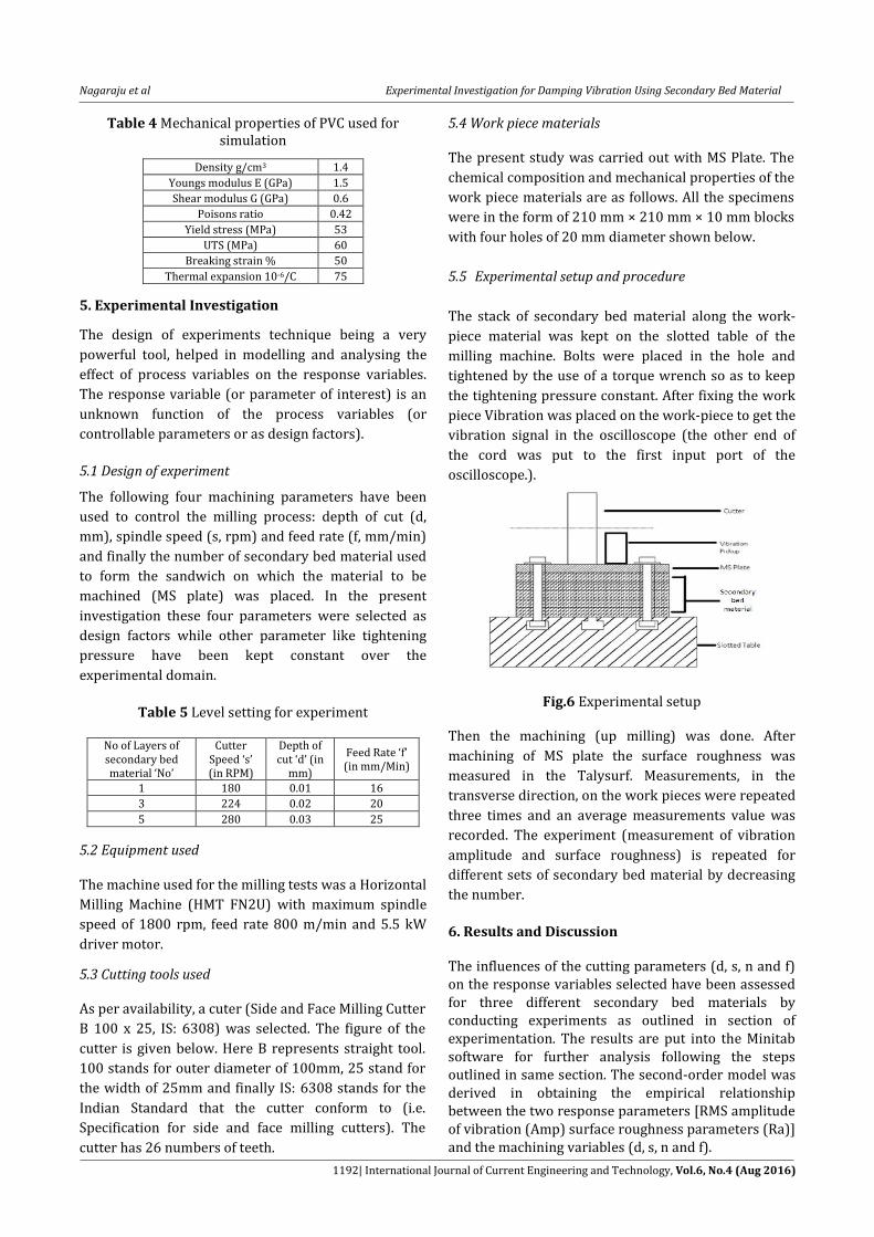
Fig.14 Normal probability plot for PVC as SBM (for
Amp)
Fig.15 Residual versus predicted response for PVC as
SBM (for Amp)
A check on the probability plot of the shows that, the residuals fall on or near a straight line. This refers that the errors are distributed normally. Also residuals versus the predicted response plot reveal that there is no obvious pattern and unusual structure. This implies that the model proposed is adequate.
Fig.16 Main effect plot for PVC as SBM (for Ra)
Fig.17 Normal probability plot for PVC as SBM (for Ra)
The normal probability plot of the residuals and the plot of residuals versus the predicted response for Ra are shown. A check on the probability plot of the shows that, the residuals fall on or near a straight line. This refers that the errors are distributed normally. Also residuals versus the predicted response plot reveal that there is no obvious pattern and unusual structure. This implies that the model proposed is adequate.
Fig.18 Residual versus predicted response for PVC as SBM for (Ra)
6.3 Analysis for glass fiber epoxy (GFE) as secondary bed material The main effect plot for secondary bed material GFE is as follows. The normal probability plot of the residuals and the plot of residuals versus the predicted response for Amp are shown. A check on the probability plot of the shows that, the residuals fall on or near a straight line. This refers that the errors are distributed normally. Also residuals versus the predicted response plot reveal that there is no obvious pattern and unusual structure. This implies that the model proposed is adequate.
Fig.19 Main effect plot for GFE as SBM (for AMP)
Fig.20 Normal probability plot for GFE as SBM (for
Amp)
Nagaraju et al Experimental Investigation for Damping Vibration Using Secondary Bed Material
1195| International Journal of Current Engineering and Technology, Vol.6, No.4 (Aug 2016)
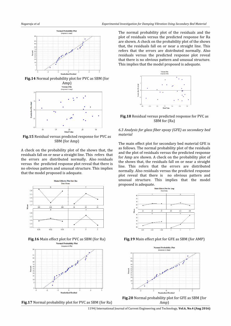
Fig.21 Residual versus predicted response for GFE as SBM for (Amp)
Fig.22 Main effect plot for GFE as SBM (for Ra)
Fig.23 Residual versus predicted response for GFE as SBM for (Ra)
Fig.24 Residual versus predicted response for GFE as SBM for (Ra)
The normal probability plot of the residuals and the plot of residuals versus the predicted response for Ra are shown. A check on the probability plot of the shows that, the residuals fall on or near a straight line. This refers that the errors are distributed normally. Also residuals versus the predicted response plot reveal that there is no obvious pattern and unusual structure. This implies that the model proposed is adequate.
Conclusions 1) In the present work, 3types of secondary bed
materials are stacked together below the work piece to form the sandwich and the main effect plot shows the variation of response parameter with respect to controllable parameter.
2) Finite Element Analysis based modal analysis helped in deducing the precautionary steps while doing the experiment.
3) RSM is utilized to develop model equation which shows the variation of response parameter with respect to controllable parameter.
4) The decrease of vibration amplitude has been observed with increase of number of layers interposed between table and work piece for PP and PVC but for GFE vibration increases of the experimental setting.
5) It can be concluded that for decided level setting PP and PVC are the useful secondary bed material than GFE.
References R H. Myers and D. C. Montgomery (2002), Response Surface
Methodology. T. Stolarski, Y. Nakasone, S. Yoshimoto, (2006) Engineering
analysis with ANSYS software, Elsevier Butterworth-Heinemann
Chandra, R., Singh S.P, and Gupta.K, (1999). Damping studies in fiber-reinforced composites—a review. Composite Structs, 46(1), 41-51.
Koo K.N, Lee.I.( 1993)Vibration and damping analysis of composite laminates using deformable finite element. AIAA J; 31 (4): 728-35.
Lin D.X, Ni R.G, Adams R.D. (1984). Prediction and measurement of the vibrational damping parameters of carbon-glass fiber-reinforced plastic Plates. J Comp Mater; 18: 132-52.
Morison W.D,(1982) The prediction of material damping of laminated composites, Can. Aeronaut. Space J. 28, pp. 372-382.
Wakasawa, Y.Masatoshi, and Etsuo, M. (2004) The damping capacity improvement of machine tool structures by balls packing‖. Int J Mach Tools Manuf, 44(14), 1527-1536.
Suh, J.D., Lee, D.G. and Kegg, R. (2002). Composite machine tool structures for high speed milling machines. Annals CIRP, 51(1), 285–288.
Rahman, M., Mansur, A. and Karim, B. (2001) Non-conventional material for machine tool structures[J]. JISM International Journal, Series C, 44(1), 1–11.
B. C. Routara & A. Bandyopadhyay and P. Sahoo, (2008) Roughness modeling and optimization in CNC end milling using response surface method: effect of workpiece material variation, Int J Adv Manuf Technol, Vol 40, PP. 1166–1180.

![300 series 1195 r11[1]](https://static.fdocuments.in/doc/165x107/589ca1ae1a28abf4148b5e95/300-series-1195-r111.jpg)