Experimental Comparison of Bernoulli Gripper and Vortex ...
10
INTERNATIONAL JOURNAL OF PRECISION ENGINEERING AND MANUFACTURING Vol. 16, No. 10, pp. 2081-2090 SEPTEMBER 2015 / 2081 © KSPE and Springer 2015 Experimental Comparison of Bernoulli Gripper and Vortex Gripper Xin Li 1,# , Ning Li 1 , Guoliang Tao 1 , Hao Liu 1 , and Toshiharu Kagawa 2 1 State Key Lab of Fluid Power Transmission and Control, Zhejiang University, 38 Zheda-road, Hangzhou, Zhejiang, 310027, China 2 Precision and Intelligence Laboratory, Tokyo Institute of Technology, Yokohama, 226-8503, Japan # Corresponding Author / E-mail: [email protected], TEL: +86-571-87951271-6403, FAX: +86-571-87951271 KEYWORDS: Bernoulli gripper, Vortex gripper, Experimental comparison, Suction, Pressure distribution, Stress A Bernoulli gripper and a vortex gripper are types of pneumatic grippers that have similar functions but different working principles. They are widely used for performing gripping, transferring, and placing operations in automated production lines. This study systematically compares the two grippers and provides an objective reference to enable users to choose an appropriate gripper. First, we present the working principles of both grippers. Then, we measure the curves of suction force, air consumption, and upstream pressure; furthermore, we analyze and compare the energy consumption from the viewpoint of the entire pneumatic system. The results reveal the relationships with the air consumption and total energy consumption. Next, we measure the pressure distribution formed on the upper surface of the workpiece. From the experimental results, the principles of the two grippers are stated and compared. Furthermore, we use the pressure distribution data to estimate the deformation and inner stress of the workpiece. The influence of the grippers on the workpiece are analyzed and compared from a material mechanics viewpoint. Finally, we use three types of rough surfaces to qualitatively evaluate and compare the performance of the grippers when gripping a workpiece with a rough surface. Manuscript received: July 4, 2014 / Accepted: July 5, 2015 1. Introduction In many production lines, a workpiece is subjected to gripping, transferring, and placing operations. These operations, although simple, are a technical bottleneck in realizing a fully automated production line owing to defects in traditional mechanical gripping tools and rubber vacuum suckers, as described below. (1) A mechanical gripping tool always has two or more splints that can open and close. The gripping operation is realized by gripping the splints and exerting force on them to make them clench. However, fragile sheet workpieces (such as solar cell piece, 1 silicon wafer, glass NOMENCLATURE D = bending stiffness E = Young's modulus gripper = gripper's energy consumption system = energy dissipation of the air supply system total = total energy g = acceleration of gravity h max = optimal gap height h w = thickness of workpiece M r = radial bending moment M a = circumferential bending moment P a = atmospheric pressure P c = outlet pressure of air compressor P u = upstream pressure of gripper q = resultant load Q = flow rate in the standard state r = radius E · E · E · R = radius of circular glass workpiece τ = shear stress δ = deformation ν = Poisson's ratio ρ = density of workpiece DOI: 10.1007/s12541-015-0270-3 ISSN 2234-7593 (Print) / ISSN 2005-4602 (Online)
Transcript of Experimental Comparison of Bernoulli Gripper and Vortex ...

INTERNATIONAL JOURNAL OF PRECISION ENGINEERING AND MANUFACTURING Vol. 16, No. 10, pp. 2081-2090 SEPTEMBER 2015 / 2081
© KSPE and Springer 2015
Experimental Comparison of Bernoulli Gripper and
Vortex Gripper
Xin Li1,#, Ning Li1, Guoliang Tao1, Hao Liu1, and Toshiharu Kagawa2
1 State Key Lab of Fluid Power Transmission and Control, Zhejiang University, 38 Zheda-road, Hangzhou, Zhejiang, 310027, China2 Precision and Intelligence Laboratory, Tokyo Institute of Technology, Yokohama, 226-8503, Japan
# Corresponding Author / E-mail: [email protected], TEL: +86-571-87951271-6403, FAX: +86-571-87951271
KEYWORDS: Bernoulli gripper, Vortex gripper, Experimental comparison, Suction, Pressure distribution, Stress
A Bernoulli gripper and a vortex gripper are types of pneumatic grippers that have similar functions but different working principles.
They are widely used for performing gripping, transferring, and placing operations in automated production lines. This study
systematically compares the two grippers and provides an objective reference to enable users to choose an appropriate gripper. First,
we present the working principles of both grippers. Then, we measure the curves of suction force, air consumption, and upstream
pressure; furthermore, we analyze and compare the energy consumption from the viewpoint of the entire pneumatic system. The results
reveal the relationships with the air consumption and total energy consumption. Next, we measure the pressure distribution formed
on the upper surface of the workpiece. From the experimental results, the principles of the two grippers are stated and compared.
Furthermore, we use the pressure distribution data to estimate the deformation and inner stress of the workpiece. The influence of
the grippers on the workpiece are analyzed and compared from a material mechanics viewpoint. Finally, we use three types of rough
surfaces to qualitatively evaluate and compare the performance of the grippers when gripping a workpiece with a rough surface.
Manuscript received: July 4, 2014 / Accepted: July 5, 2015
1. Introduction
In many production lines, a workpiece is subjected to gripping,
transferring, and placing operations. These operations, although simple,
are a technical bottleneck in realizing a fully automated production line
owing to defects in traditional mechanical gripping tools and rubber
vacuum suckers, as described below.
(1) A mechanical gripping tool always has two or more splints that
can open and close. The gripping operation is realized by gripping the
splints and exerting force on them to make them clench. However,
fragile sheet workpieces (such as solar cell piece,1 silicon wafer, glass
NOMENCLATURE
D = bending stiffness
E = Young's modulus
gripper = gripper's energy consumption
system = energy dissipation of the air supply system
total = total energy
g = acceleration of gravity
hmax = optimal gap height
hw = thickness of workpiece
Mr = radial bending moment
Ma = circumferential bending moment
Pa = atmospheric pressure
Pc = outlet pressure of air compressor
Pu = upstream pressure of gripper
q = resultant load
Q = flow rate in the standard state
r = radius
E·
E·
E·
R = radius of circular glass workpiece
τ = shear stress
δ = deformation
ν = Poisson's ratio
ρ = density of workpiece
DOI: 10.1007/s12541-015-0270-3 ISSN 2234-7593 (Print) / ISSN 2005-4602 (Online)

2082 / SEPTEMBER 2015 INTERNATIONAL JOURNAL OF PRECISION ENGINEERING AND MANUFACTURING Vol. 16, No. 10
panel2) cannot be gripped using the mechanical gripping tool. Moreover,
mechanical wear occurs in the components, leading to a heavy daily
maintenance load.
(2) The rubber vacuum sucker is an effective tool for gripping a
sheet workpiece.3,4 However, it is limited to gripping flat and smooth
workpieces. With a coarse workpiece, the pressure difference between
the negative pressure inside the rubber sucker and the external
atmospheric pressure causes reverse flow of air into the sucker through
the gaps on the workpiece surface, causing the negative pressure inside
the sucker to be lost and the vacuum absorption to become ineffective.
Furthermore, dust, fragments, residues, and food juices can easily be
absorbed into the rubber sucker, causing the blocking of the vacuum
tube and the failure of the vacuum source.
In many food and leather production lines, the transferring, sorting,
and boxing of workpieces can only be accomplished through manual
operations. To change this situation, two types of grippers - Bernoulli
gripper and vortex gripper - were developed by researchers. In these
grippers, negative pressure is generated using the inertial effect of air
flow. These grippers can be used to pick up and grip a workpiece with
a coarse surface. Both grippers show similar performance, and thus far,
no study has systematically compared them. This has resulted in the
lack of a frame of reference when deciding which gripper to choose. To
address this issue, in this study, the suction of a Bernoulli gripper and
a vortex gripper was compared in terms of the energy consumption,
pressure distribution, deformation, and inner stress of the workpiece,
and the effect of a coarse workpiece surface was evaluated. From the
comparison results, the differences between the two grippers were
summarized to provide an objective frame of reference for users when
establishing an automatic production line.
2. Working Principles
2.1 Bernoulli gripper
The Bernoulli gripper’s original structural design is very simple (see
Fig. 1(a)). Its key components are a circular plate with an air hole at its
center. There is a rubber pad on the underside of this plate, and a radial
gap flow channel is formed between the workpiece and the plate.
Driven by upstream pressure, air flows into the Bernoulli gripper along
the central air hole and then turns into the radial gap flow channel.
Because the cross-sectional area of the radial gap channel increases, the
air flow velocity in the channel decreases. According to Bernoulli’s
principle, a flow with decreasing velocity is accompanied by increasing
pressure. In other words, the internal pressure becomes smaller than the
external pressure. Moreover, because the external pressure on the plate
is actually the atmospheric pressure, there exists a negative pressure
that is lower than the atmospheric pressure inside the plate, and
therefore, upward suction is applied by the negative pressure to absorb
the workpiece. Dini and Li’s result shows that this suction is dependent
on the height of the gap flow channel (i.e., thickness of rubber pad)
between the plate and the workpiece.5,6 The relationship between the
suction and the gap height can be described by a non-monotonic curve
(see Fig. 2). Li’s study reveals that this is because of the alternation
between the viscosity effect and the inertial effect of the air flow. When
the gap height is very small, the viscosity of air flow plays the
dominant role. However, as the gap height increases, the inertial effect
of air flow dominates. Therefore, the curve of the suction force shows
two different variation trends.6 In the region with small gap height, the
suction increases sharply as the gap height increases. However, when
the gap height increases further, the suction force decreases gradually.
The maximum suction force appears at the transition phase of the two
variation trends. The corresponding gap height is the optimal design
value of the thickness of the rubber pad, which is denoted as hmax. In
general, hmax is a value of the magnitude of several hundreds of
microns. Based on the original design, many researchers have proposed
an optimized design for a Bernoulli gripper.5,7,8 Fig. 1(b) shows the
most classical and widely used design. The deflector at the center of the
plate serves to block the dynamic pressure of air flow acting on the
workpiece with changing flow direction. Air is blown out with a high
radial velocity component through a narrow circular outlet between the
deflector and the plate. This design can increase the Bernoulli effect
and the resulting suction force.
The main difference between the Bernoulli gripper and a traditional
rubber vacuum sucker is that the exhaust air flows between the
Bernoulli gripper and the workpiece. As a result, external air cannot
Fig. 1 Schematic diagrams of Bernoulli gripper
Fig. 2 Force and gap height of Bernoulli gripper

INTERNATIONAL JOURNAL OF PRECISION ENGINEERING AND MANUFACTURING Vol. 16, No. 10 SEPTEMBER 2015 / 2083
flow reversely into the negative pressure area at the center of the
gripper. Therefore, though the workpiece surface is very coarse, no
vacuum leaks occur. Fig. 3 shows the handling of a solar cell piece
using a Bernoulli gripper (Festo).
2.2 Vortex gripper
Fig. 4 shows a schematic diagram of the vortex gripper developed
by Li.9-11 From top to bottom, the gripper consists of a cover board, a
hollow cylinder, gaskets, an annular baffle, and a rubber sheet. The
cover board seals the upper end of the hollow cylinder, forming an
upside-down cup-like cavity. Tangential nozzles are arranged on the
inner surface of the hollow cylinder, and the upstream ends of the
nozzles are connected to the compressed air source. The annular baffle
is fixed to the hollow cylinder by using bolts. By placing gaskets
between the baffle and the cylinder, an annular gap passage is formed.
The gap passage connects the cavity to the outside atmosphere. To
increase friction between the gripper and the workpiece, a soft rubber
sheet layer is stuck to the lower end surface of the baffle. High-pressure
air is injected into the cavity through tangential nozzles, and it flows
along the circular surface of the cavity to form a rotating air flow. The
centrifugal force of the rotating flow reduces the pressure in the central
area below that in the periphery. In addition, the pressure in the
periphery is lowered to near atmospheric pressure by connecting the
periphery to the atmosphere via the gap passage. Therefore, negative
pressure is generated in the central area of the cavity. The suction force
produced by the negative pressure picks up a workpiece placed under
the gripper. Air is exhausted through the gap passage after rotating in
the cavity. The outward exhaust of air prevents outside air from flowing
into the gripper. As a result, the negative pressure in the gripper is
maintained. Therefore, the vortex gripper can pick up workpieces with
a coarse surface. Fig. 5 shows the use of a vortex gripper to pick up a
circuit board with electronic components of varying size welded on its
surface. Our previous research revealed that the gasket thickness is a
key design parameter that affects the suction force. In Fig. 6, the curve
of the gasket thickness and suction force reveals that an optimal height
value hmax exists; furthermore, this value remains nearly constant
when the supplied flow rate exceeds a certain level.
Fig. 3 Handling of a solar cell piece using a Bernoulli gripper
Fig. 4 Schematic diagrams of vortex gripper
Fig. 5 Vortex gripper picking up a printed circuit board
Fig. 6 Suction force and gasket height (air flow rate: 21 L/min)
2084 / SEPTEMBER 2015 INTERNATIONAL JOURNAL OF PRECISION ENGINEERING AND MANUFACTURING Vol. 16, No. 10
3. Experimental Methods
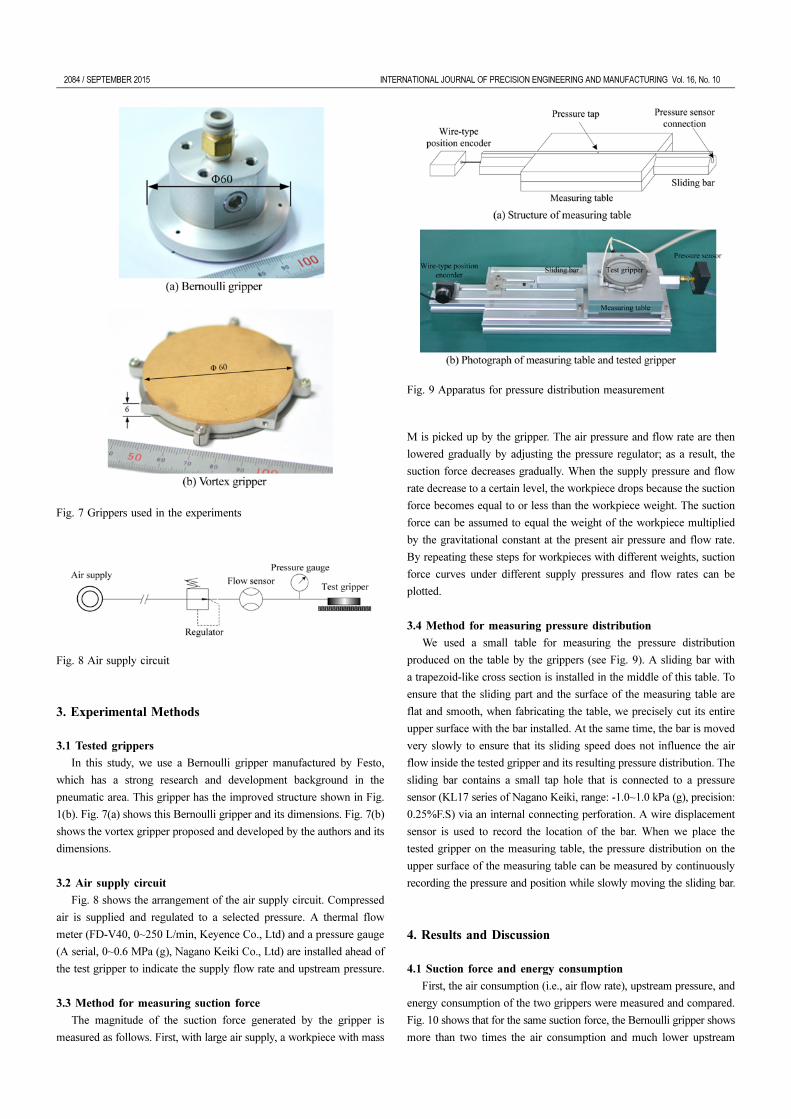
3.1 Tested grippers
In this study, we use a Bernoulli gripper manufactured by Festo,
which has a strong research and development background in the
pneumatic area. This gripper has the improved structure shown in Fig.
1(b). Fig. 7(a) shows this Bernoulli gripper and its dimensions. Fig. 7(b)
shows the vortex gripper proposed and developed by the authors and its
dimensions.
3.2 Air supply circuit
Fig. 8 shows the arrangement of the air supply circuit. Compressed
air is supplied and regulated to a selected pressure. A thermal flow
meter (FD-V40, 0~250 L/min, Keyence Co., Ltd) and a pressure gauge
(A serial, 0~0.6 MPa (g), Nagano Keiki Co., Ltd) are installed ahead of
the test gripper to indicate the supply flow rate and upstream pressure.
3.3 Method for measuring suction force
The magnitude of the suction force generated by the gripper is
measured as follows. First, with large air supply, a workpiece with mass
M is picked up by the gripper. The air pressure and flow rate are then
lowered gradually by adjusting the pressure regulator; as a result, the
suction force decreases gradually. When the supply pressure and flow
rate decrease to a certain level, the workpiece drops because the suction
force becomes equal to or less than the workpiece weight. The suction
force can be assumed to equal the weight of the workpiece multiplied
by the gravitational constant at the present air pressure and flow rate.
By repeating these steps for workpieces with different weights, suction
force curves under different supply pressures and flow rates can be
plotted.
3.4 Method for measuring pressure distribution
We used a small table for measuring the pressure distribution
produced on the table by the grippers (see Fig. 9). A sliding bar with
a trapezoid-like cross section is installed in the middle of this table. To
ensure that the sliding part and the surface of the measuring table are
flat and smooth, when fabricating the table, we precisely cut its entire
upper surface with the bar installed. At the same time, the bar is moved
very slowly to ensure that its sliding speed does not influence the air
flow inside the tested gripper and its resulting pressure distribution. The
sliding bar contains a small tap hole that is connected to a pressure
sensor (KL17 series of Nagano Keiki, range: -1.0~1.0 kPa (g), precision:
0.25%F.S) via an internal connecting perforation. A wire displacement
sensor is used to record the location of the bar. When we place the
tested gripper on the measuring table, the pressure distribution on the
upper surface of the measuring table can be measured by continuously
recording the pressure and position while slowly moving the sliding bar.
4. Results and Discussion
4.1 Suction force and energy consumption
First, the air consumption (i.e., air flow rate), upstream pressure, and
energy consumption of the two grippers were measured and compared.
Fig. 10 shows that for the same suction force, the Bernoulli gripper shows
more than two times the air consumption and much lower upstream
Fig. 7 Grippers used in the experiments
Fig. 8 Air supply circuit
Fig. 9 Apparatus for pressure distribution measurement

INTERNATIONAL JOURNAL OF PRECISION ENGINEERING AND MANUFACTURING Vol. 16, No. 10 SEPTEMBER 2015 / 2085
pressure than the vortex gripper. We believe that this is because a large
air flow is necessary for the Bernoulli gripper to achieve a significant
deceleration of radial velocity. Hence, the cross-sectional area of the
circular outlet is designed to be large in order to blow out a large
quantity of air at a relatively low upstream pressure. In contrast, the
vortex gripper has only two tangential nozzles with 0.8-mm diameter.
The high upstream pressure is used to inject air from the two tangential
holes. Then, a high-speed spinning air flow is generated in the cavity.
The flow and upstream pressure requirements are different owing to the
different working principles of the two types of grippers. The energy
consumption of the grippers is an important evaluation index. In this
article, Cai’s algorithm is used to calculate the energy of compressible
air. The gripper’s energy consumption ( gripper) is calculated as follows:
(1)
where Pa is the atmospheric pressure; P
u, the upstream pressure; and Q,
the flow rate in the standard state. This equation thus converts the
upstream pressure and flow rate into energy (unit: Watt). The vortex
gripper has lower air consumption yet much higher upstream pressure
than the Bernoulli gripper; therefore, the vortex gripper has relatively
lower energy consumption (see Fig. 10). However, this is not our final
conclusion. Next, the energy consumption problem is considered from
the viewpoint of the overall pneumatic system. The two types of
grippers are pneumatic end effectors that need to be connected with a
compressed air supply system (see Fig. 11). In general, compressed air
reaches the gripper after passing through many pneumatic components
such as the cooler, dehumidifier, filter, piping system, regulators, and
switching valve. In this process, a large amount of energy is
unavoidably dissipated. More importantly, the larger the air flow, the
greater is the energy dissipation of the air supply system. Then, when
the gripper is used, the total energy consumed ( total) is the sum of the
energy consumption gripper of the gripper itself and the energy
dissipation of the air supply system ( system). The total energy total
can be calculated by substituting Pu in Eq. (1) with the outlet pressure
of the air compressor (Pc). Considering that on a production line, the air
for the gripper is supplied by decreasing the pressure using regulator(s)
instead of configuring a low-pressure air source for the gripper,
irrespective of the upstream pressure of the gripper, the comparison of
the total energy total is only dependent on the air flow rate. The outlet
E·
E·gripper P
aQ P
u/P
a( )ln=
E·
E·
E·
E·
E·
Fig. 10 Comparison of flow rate, upstream pressure, and energy
consumption
Fig. 11 Compressed air supply system

2086 / SEPTEMBER 2015 INTERNATIONAL JOURNAL OF PRECISION ENGINEERING AND MANUFACTURING Vol. 16, No. 10
of the compressor configured in our laboratory is 700 kPa (g), and the
total energy of the two types of grippers is shown in Fig. 12. Because
the air consumption of the vortex gripper is very low, its total energy
is only half that of the Bernoulli gripper.
The above discussion clearly suggests that the vortex gripper is
advantageous in terms of energy saving relative to the Bernoulli
gripper.
4.2 Pressure distribution
Fig. 13 shows the measurement results of the pressure distribution
when the same suction force (1.0 N) is generated for the two types of
grippers. To generate a suction force of 1.0 N, the Bernoulli gripper and
vortex gripper respectively require an air flow of 36.0 and 15.0 L/min.
Despite the fact that the pressure distributions of the two grippers, as
shown in Fig. 13, are very similar, the mechanisms of generating the
negative pressure are quite different.
The Bernoulli gripper injects air from the circular gap at high radial
velocity, following which air flows with decreasing velocity along the
radius. Hence, the pressure changes from negative to atmospheric
pressure. Because there is no air flow below the deflector, the pressure
distribution at the central part of the gripper is uniform without any
obvious pressure variation. Moreover, a pressure distribution is observed
slightly beyond atmospheric pressure in the periphery of the gripper (20
< r < 30 mm). This is caused by the viscous friction between the
airflow and the walls (i.e., the bottom surface of the Bernoulli gripper
and the upper surface of the workpiece).
In contrast, the vortex gripper injects high-pressure air into the cavity
through tangential nozzles, following which air flows along the circular
surface of the cavity to form a rotating air flow layer. The rotating air
flow induces a cupped pressure distribution in the cavity. No obvious
pressure variation is observed in the central area. It is suggested that the
air in the central area does not rotate with the external rotating air flow
layer. This phenomenon has already been observed in CFD simulations.
The CFD simulation results show that the flow velocity decreases sharply
from the periphery to the center, forming a flat pressure distribution
pattern in the central area. Furthermore, a slightly negative pressure is
observed at the contact area (r > 25 mm) between the annual rubber
sheet and workpiece. In the ideal case (rubber sheet and workpiece have
tight contact), there will be no negative pressure. However, in reality,
the workpiece and rubber sheet cannot be in tight contact. Therefore,
the negative pressure in the cavity and the external atmospheric pressure
create a tiny amount of air flow between the workpiece and the rubber
sheet, which produces the pressure distribution in the contact area.
Both types of grippers show low pressure distributions in the central
area, and the peripheral pressure is near to the atmospheric pressure.
Hence, the external air can be effectively prevented from flowing
reversely into the grippers.
4.3 Stress and deformation
The pressure distribution generated by the gripper acts directly on
the workpiece surface. As a result, shear stress (τ), circumferential and
radial bending moment (Mr and Mα, respectively), and deformation (δ)
are produced on the workpiece. The stress and deformation are harmful
for some fragile thin workpieces (such as solar cells and LCD glass
panels). Therefore, when choosing a gripper, it is necessary to consider
the potential hazards caused by its pressure distribution. There is no
method to directly measure the stress and deformation of the
workpiece. However, it is believed that these can be estimated by using
the experimental pressure distribution results.
Next, we study the situation of gripping a circular workpiece. The
workpiece is subjected to three external forces (see Fig. 14): uniformly
distributed gravity, negative pressure distribution of the gripper, and
Fig. 12 Comparison of total energy
Fig. 13 Pressure distributions formed on the upper surface of the
workpiece for generating 1-N suction force

INTERNATIONAL JOURNAL OF PRECISION ENGINEERING AND MANUFACTURING Vol. 16, No. 10 SEPTEMBER 2015 / 2087
contact force between the gripper and the workpiece. Because the
pressure distributions shown in Fig. 13 are all basically axisymmetric, it
can be considered a two-dimensional axisymmetric case. The workpiece
is subjected to the resultant load q(r), and then, the corresponding shear
force τ(r) is produced inside the workpiece. At any position with radius
r, the shear force τ(r) is given as follows:
(2)
The shear force causes the workpiece to deform. The relationship
between the shear force and the deformation is shown as follows:
(3)
where D is the bending stiffness, as defined by the following equation.
(4)
ν is Poisson’s ratio, i.e., the ratio of the lateral deformation to the
vertical deformation of the material. Poisson’s ratio is determined by
the type of material. For example, it is 0.24~0.3 for glass and ~0.3 for
metallic material. E is Young’s modulus of the material, and hw is the
thickness of the workpiece. The deformation δ(r) produces radial and
circumferential bending moments (Mr and Mα) (see Fig. 15) inside the
workpiece, respectively calculated as follows:
(5)
(6)
To solve the deformation and stress, the following boundary
conditions are required.
(1) The peripheral position is set to the reference point for the
deformation, i.e., δ = 0, where r = radius of the workpiece R.
(2) Because this is an axisymmetric problem, the deformation
variation at the center is zero, i.e., dδ /dr = 0, where r = 0.
(3) The peripheral position is a free end without any constraints, and
therefore, the radial bending moment is zero, i.e., Mr = 0, where r = R.
Thus, the deformation and internal stress can be solved by the
flowchart shown in Fig. 16. Considering that two of the boundary
conditions are at the periphery, we start the calculation circle from r =
τ r( ) 1
2π r--------- q r( )
0
r
∫– 2π rdr⋅=
τ r( )D
---------–d3δ r( )
dr3
--------------- 1
r---
d2δ r( )
dr2
---------------1
r2
----dδ r( )
dr-------------–+=
DEh
w
3
12 1 ν2
–( )-----------------------=
Mr
r( ) Dd2δ r( )
dr2
--------------- ν
r---
dδ r( )dr
-------------+⎝ ⎠⎜ ⎟⎛ ⎞
–=
Mα
r( ) Dd2δ r( )
dr2
--------------- 1
r---
dδ r( )dr
-------------+⎝ ⎠⎜ ⎟⎛ ⎞
–=
Fig. 14 A circular workpiece with a symmetrically distributed load
Fig. 15 Bending moment of a tiny volume
Fig. 16 Flowchart of calculation

2088 / SEPTEMBER 2015 INTERNATIONAL JOURNAL OF PRECISION ENGINEERING AND MANUFACTURING Vol. 16, No. 10
R. The inverse integration from the periphery to the center is employed.
X is the predicted value of dδ /dr at the position r = R. After one circle
ends, X is revised according to whether dδ /dr at r = 0 is zero, and then,
a new circle begins. The calculation ends when the condition
( ) is met.
One typical application of these types of grippers is for the assembling
line of a mobile panel. Therefore, a thin glass disk workpiece (hw = 0.6
mm, D = 0.3, E = 48 GPa, ρ = 3000 kg/m3, and R = 50 mm) is taken
as an example to study the deformation δ(r), internal stress τ (r), and
bending moments Mr(r) and Mα(r) generated in the glass disk by the
pressure distribution of the two grippers. After being picked up and
gripped, the glass workpiece stays in a force equilibrium state under the
action of three forces: pressure distribution of gripper, its own uniform
gravity distribution, and contact pressure between the gripper and itself.
In the last section, the pressure distribution was measured experimentally.
Hence, the experimental values shown in Fig. 13 can be directly used
for the calculation. With the density and thickness of the glass workpiece
already known, its uniform gravity distribution (= ρghw) can be obtained.
Moreover, because the workpiece stays in the force equilibrium state,
the contact force between the gripper and itself can be easily calculated.
It should be noted that the contact pressure is supposed to distribute
uniformly. This assumption is beneficial to simplify the calculation,
and it is believed that this treatment will not fundamentally affect the
comparison result. Fig. 17 shows the calculation result. Under the
action of an external load, the shear force and bending moment vary
along the radial direction. The bending moment causes the glass
workpiece to deform, and extrusion/stretching stress is generated inside
the workpiece. Excessive shear force and extrusion stress will damage
the material, and deformation of the workpiece will influence the
assembly accuracy. The result in Fig. 17 indicates that the vortex gripper
shows larger deformation and bending moment but smaller shearing
force than the Bernoulli gripper. However, because these differences
are very small, it is considered that the two types of grippers do not
differ obviously in these respects.
4.4 Influence of surface roughness
The Bernoulli gripper and vortex gripper discussed in this study can
pick up workpieces with a coarse surface, unlike traditional rubber
suckers, because they generate a negative pressure while constantly
exhausting air. This effectively prevents the external air from flowing
reversely into the grippers. In this section, the influence of the surface
roughness of the workpiece on the two types of grippers is studied. To
quantitatively investigate and evaluate the effect of surface roughness
on suction force, we used sandpaper. The roughness of sandpaper is
evaluated by the grit size, which refers to the size of the particles of
abrading materials embedded in the sandpaper. The roughness of the
sandpaper surface increases as the grit size decreases. Fig. 18 shows the
dδ r( )dr
-------------r 0=
0→
Fig. 17 Load and resulting deformation and inner stress

INTERNATIONAL JOURNAL OF PRECISION ENGINEERING AND MANUFACTURING Vol. 16, No. 10 SEPTEMBER 2015 / 2089
three types of surfaces used in the experiments: a smooth surface and
150 and 60 grit sandpaper. 150 grit sandpaper has small and fine
particles, whereas 60 grit sandpaper has protruding sand particles
distributed evenly on its surface.
Fig. 19 shows the experimental result. As the surface of the
workpiece becomes coarse, both grippers need to consume more energy
to generate the same suction force. We believe that this is because the
coarse surface blocks the air flow. When the Bernoulli gripper injects
air through the gap flow tunnel, the coarse surface will undoubtedly
increase the viscous friction. Hence, the pressure in the gap tunnel is
raised, and thus, the negative pressure and suction force are decreased.
For the vortex gripper, the coarse surface weakens the rotation of air
and decreases the effect of centrifugal force of the rotating air. Thus,
the negative pressure and suction force are weakened. Moreover, the
extents of influence on the vortex gripper are observed to be slightly
larger than on the Bernoulli gripper. In the present test sandpapers, the
vortex gripper still maintains the advantage of low energy consumption
when gripping a workpiece with a coarse surface. However, the vortex
gripper may lose this advantage when the surface becomes very rough
and rugged.
5. Conclusion
In this study, we presented the working principles of the Bernoulli
gripper and vortex gripper. Then, we experimentally analyzed and
compared the energy consumption, pressure distribution, deformation
and internal stress of workpiece, and impact due to surface roughness.
From the experimental results, the following conclusions can be derived.
(1) When the same suction force is generated, the operating condition
for the Bernoulli gripper is low upstream pressure and large flow rate,
whereas that for the vortex gripper is high upstream pressure and low
flow rate. From the perspective of total energy including energy loss of
the pipe system, the vortex gripper with low flow rate has a greater
advantage in terms of energy saving.
(2) Though the air flow forms of the two types of grippers are quite
different, the pressure distributions are similar with a low pressure being
distributed in the central area and the peripheral pressure approaching
the atmospheric pressure. Hence, external air can be effectively prevented
from flowing reversely into the gripper.
(3) The workpiece deforms under the action of its gravity, negative
pressure distribution of gripper, and contact force between the gripper
and itself. According to the material mechanics model, the experimental
results of pressure distribution are used to infer the deformation and
internal stress of the workpiece. Because the pressure distributions of
the two types of grippers are similar, the deformation and internal stress
of the workpiece are at the same level.
(4) When the workpiece surface becomes rough, the two types of
grippers need to consume more energy to generate the same suction as
when gripping a workpiece with a smooth surface. The experimental
results reveal that the surface roughness has a slightly larger influence
on the vortex gripper than on the Bernoulli gripper. It implies that the
vortex gripper may lose its advantage in terms of energy saving when
the workpiece surface becomes very rough and rugged.
ACKNOWLEDGEMENT
This work is supported by the National Natural Science Foundation
of China (No. 51375441) and the Science Fund for Creative Research
Groups of National Natural Science Foundation of China (No. 51221004).
Fig. 18 Views of surfaces used for experiment
Fig. 19 Influence of workpiece’s surface roughness

2090 / SEPTEMBER 2015 INTERNATIONAL JOURNAL OF PRECISION ENGINEERING AND MANUFACTURING Vol. 16, No. 10
REFERENCES
1. Brun, X. F. and Melkote, S. N., “Analysis of Stresses and Breakage
of Crystalline Silicon Wafers during Handling and Transport,” Solar
Energy Materials and Solar Cells, Vol. 93, No. 8, pp. 1238-1247,
2009.
2. Isobe, H., Fushmi, M., Ootsuka, M., and Kyusojin, A., “Non-
Contact Transportation of Flat Panel Substrate by Combined
Ultrasonic Acoustic Viscous and Aerostatic Forces,” Int. J. Precis.
Eng. Manuf., Vol. 8, No. 2, pp. 44-48, 2007.
3. Lundström, G., “Industrial Robot Grippers,” Industrial Robot: An
International Journal, Vol. 1, No. 2, pp. 72-82, 1974.
4. Mantriota, G., “Theoretical Model of the Grasp with Vacuum
Gripper,” Mechanism and Machine Theory, Vol. 42, No. 1, pp. 2-17,
2007.
5. Dini, G., Fantoni, G., and Failli, F., “Grasping Leather Plies by
Bernoulli Grippers,” CIRP Annals-Manufacturing Technology, Vol.
58, No. 1, pp. 21-24, 2009.
6. Li, X. and Kagawa, T., “Theoretical and Experimental Study of
Factors Affecting the Suction Force of a Bernoulli Gripper,” Journal
of Engineering Mechanics, Vol. 140, No. 9, Paper No. 04014066,
2014.
7. Davis, S., Gray, J. O., and Caldwell, D. G., “An End Effector based
on the Bernoulli Principle for Handling Sliced Fruit and
Vegetables,” Robotics and Computer-Integrated Manufacturing, Vol.
24, No. 2, pp. 249-257, 2008.
8. Brun, X. F. and Melkote, S. N., “Modeling and Prediction of the
Flow, Pressure, and Holding Force Generated by a Bernoulli
Handling Device,” Journal of Manufacturing Science and
Engineering, Vol. 131, No. 3, Paper No. 031018, 2009.
9. Li, X., Kawashima, K., and Kagawa, T., “Analysis of Vortex
Levitation,” Experimental Thermal and Fluid Science, Vol. 32, No.
8, pp. 1448-1454, 2008.
10. Li, X., Iio, S., Kawashima, K., and Kagawa, T., “Computational
Fluid Dynamics Study of a Noncontact Handling Device using Air-
Swirling Flow,” Journal of Engineering Mechanics, Vol. 137, No. 6,
pp. 400-409, 2011.
11. Xin, L., Zhong, W., Kagawa, T., Liu, H., and Tao, G., “Development
of a Pneumatic Sucker for Gripping Workpieces with Rough
Surface,” IEEE Transactions on Automation Science and
Engineering, DOI NO: 10.1109/TASE.2014.2361251, 2014.