
Experimental and Numerical Study of Spoiler Effect on Ship ...
14
Mostafa et al. CFD Letters Vol. 1(1) 2009 29 www.cfdl.issres.net Vol. 1 (1) – July 2009 Experimental and Numerical Study of Spoiler Effect on Ship Stability: Effect of Spoiler Inclination Angle Nabil H. Mostafa 1 c , Berge Djebedjian 2 , Emad M. S. El-Said 3 , Magdy Abou Rayan 2 1 Mechanical Power Engineering Department, College of Engineering Zagazig University, Zagazig, EGYPT 2 Mechanical Power Engineering Department, Faculty of Engineering Mansoura University, Mansoura, EGYPT 3 El-Nasr Casting Company, Ductile Iron Pipes Industry Embaba, Cairo, EGYPT Received: 25/07/2009 – Revised 29/07/2009 – Accepted 30/07/2009 Abstract Ship stability is studied experimentally and numerically. The injection of air or exhaust gas stabilizes cavities behind spoilers. The spoiler system is tested experimentally to understand the parameters affecting the flow field and bubble formation around the spoiler. These parameters are the spoiler inclination angle, rise of floor angle and injected air position. The spoiler inclination angle effect is studied in this paper. The images of flow field variation and bubble formation are recorded with scientific video camera and compared with the computed flow field at different conditions and time sequence. The two-phase flow field around a ship spoiler with the free surface simulation in Piecewise Linear Interface Construction method is modeled numerically using a three-dimensional Navier-Stokes code. The bubbles shape, the three-dimensional flow field around the spoiler body and the pressure variation on the wake of the spoiler body are computed. The comparison between the numerical and experimental results shows a good matching of bubble formation and the difference may be attributed to the laminar flow computation without including turbulence effects. The moment around the 90 inclined spoiler fixation line is 1.651 times that around the 30 inclined spoiler and 1.1 times that around the 60 inclined spoiler after 1 second. Therefore, varying the spoiler inclination angle produces different bubble shapes and consequently different forces are introduced to control the roll, pitch motion and speed of the ship leading to ship stability. Keywords: Ship, Spoiler; Cavitation; Hydrofoils; Free surface; Two-Phase Flow. 1. Introduction The motion of a ship in six degrees of freedom is considered as a translation motion (position) in three directions: surging, swaying, and heaving; and as a rotation motion (orientation) about three axes: rolling, pitching and yawing, Fig. (1), Clark [1]. Heaving being the vertical motion of the ship, c Corresponding Author: Nabil H. Mostafa Email: [email protected] © 2009-2012 All rights reserved. ISSR Journals
Transcript of Experimental and Numerical Study of Spoiler Effect on Ship ...

Mostafa et al. CFD Letters Vol. 1(1) 2009
29
www.cfdl.issres.net Vol. 1 (1) – July 2009
Experimental and Numerical Study of Spoiler Effect on Ship Stability: Effect of Spoiler Inclination Angle
Nabil H. Mostafa1 c , Berge Djebedjian2, Emad M. S. El-Said3, Magdy Abou Rayan2
1Mechanical Power Engineering Department, College of EngineeringZagazig University, Zagazig, EGYPT
2Mechanical Power Engineering Department, Faculty of EngineeringMansoura University, Mansoura, EGYPT
3El-Nasr Casting Company, Ductile Iron Pipes IndustryEmbaba, Cairo, EGYPT
Received: 25/07/2009 – Revised 29/07/2009 – Accepted 30/07/2009
Abstract
Ship stability is studied experimentally and numerically. The injection of air or exhaust gas stabilizes cavities behind spoilers. The spoiler system is tested experimentally to understand the parameters affecting the flow field and bubble formation around the spoiler. These parameters are the spoiler inclination angle, rise of floor angle and injected air position. The spoiler inclination angle effect is studied in this paper. The images of flow field variation and bubble formation are recorded with scientific video camera and compared with the computed flow field at different conditions and time sequence. The two-phase flow field around a ship spoiler with the free surface simulation in Piecewise Linear Interface Construction method is modeled numerically using a three-dimensional Navier-Stokes code. The bubbles shape, the three-dimensional flow field around the spoiler body and the pressure variation on the wake of the spoiler body are computed. The comparison between the numerical and experimental results shows a good matching of bubble formation and the difference may be attributed to the laminar flow computation without including turbulence effects. The moment around the 90 inclined spoiler fixation line is 1.651 times that around the 30 inclined spoiler and 1.1 times that around the 60 inclined spoiler after 1 second. Therefore, varying the spoiler inclination angle produces different bubble shapes and consequently different forces are introduced to control the roll, pitch motion and speed of the ship leading to ship stability.
Keywords: Ship, Spoiler; Cavitation; Hydrofoils; Free surface; Two-Phase Flow.
1. Introduction
The motion of a ship in six degrees of freedom is considered as a translation motion (position) in three directions: surging, swaying, and heaving; and as a rotation motion (orientation) about three axes: rolling, pitching and yawing, Fig. (1), Clark [1]. Heaving being the vertical motion of the ship,
c Corresponding Author: Nabil H. MostafaEmail: [email protected]© 2009-2012 All rights reserved. ISSR Journals

Experimental and Numerical Study of Spoiler Effect on Ship Stability: Effect of Spoiler Inclination Angle
30
whilst swaying and surging are respectively the athwart-ship motion and the fore and aft motion. Rolling is rotation about a longitudinal axis, while pitching is rotation above a transverse axis and yawing is rotation about a vertical axis. Pitching and rolling are true oscillatory motions. The control and reduction of ship motion is important as it is related to the structural loading and comfort of a ship.
On the other hand, resistance of a ship is decomposed into three components; the wave-making resistance, the frictional drag, and the viscous form drag. The reduction of the wave-making resistance is achieved through modification of hull forms. The reduction of ship frictional drag has been investigated using many techniques, e.g., microbubbles [2], air films, [3], riblets [4], super-water-repellent surface and air injection [5] etc.
The control and reduction of ship motions can be realized by using a system of spoilers mounted at the bottom of the ship. The basic idea of using spoilers is that two flow fields with different pressures are created, one of them in upstream region and the other one in downstream region. Hence, the pressure difference is carried out in low speed flow field, so the pressure drop in downstream region can be increased by air injection. This creates two-phase flow; air and water; with high density ratio that plays an important role in dynamic pressure and total pressure values. The pressure difference between the two regions generates forces acting on the spoiler; these forces are used to control and reduce ship motions.
Spoilers can be classified into bow spoilers and stern spoilers, Figure 2. The bow spoilers consist of an even number of sections arranged port and starboard forward of the center of mass of the ship. The stern spoilers consist of an even number of sections arranged port and starboard attached to the ship transom or transom plate.
Heaving
Yawing
Rolling
Pitching
Surging
Swaying
StarboardStern
spoilerBow spoiler
×
×Port
CG
Rudder
Figure (1) Ship degrees of freedom, Clark [1]
Figure (2) Example of ship spoiler locations, Soper et al. [6]
Hull-mounted cavitating spoilers have been shown by the Krylov Shipbuilding Research Institute (Russia) to be an effective means for motion reduction in high-speed displacement-hull vessels. The specific design details of the Russian system are not available for propriety reasons. Their results, quoted by Soper et al. [6], show that by appropriately choosing the number, extension, and distribution of the spoilers, one can affect an optimal trim of the ship over the whole speed ranges and a reduction in the ship motion when moving in waves. Depending on the sea state, roll reduction by a factor of 2 to 5 and pitch reduction by a factor of 1.2 to 1.5 can be achieved. Consequently, an increase in the efficiency and hence the speed are by a factor of 10% to 20%. Under “MURI” research project, a theoretical investigation of the effectiveness and design of such a system has been undertaken by Soper et al. [6]. They used the panel method by developing a two-dimensional quasi-steady numerical local model for the fixed-cavitation region. The computational-fluid-dynamics boundary-element model is based on a distributed-vorticity potential-flow form. The steady-flow streamlines are determined via an iterative approach that converges to a pre-specified level of accuracy. The cavity shape and quasi-steady hydrodynamic forces have been generated

Mostafa et al. CFD Letters Vol. 1(1) 2009
31
over a wide range of forward-speed/cavity-pressure and spoiler-projection-angle parameter values. Owis et al. [7] developed a code of Navier-Stokes equations with cavitation procedure function of local pressure and density to solve the same problem.
The cavitation phenomenon depends on the local pressure and density [8]. The fundamental of ship spoiler problem is different. It depends on air injection into water and it is not a very high speed phenomenon. Mostafa [9], [10] analyzed the transient two-dimensional flow around ship spoiler numerically and experimentally, by choosing spoiler inclination angles at 45 and 90 with different air injection positions. The moment around the 45 spoiler fixation point is seven times that around the 90 spoiler. In double injection condition beside and at a distance equal to the horizontal spoiler length downstream the spoiler, the bubbles are more stable and the moment is higher by 7.9 and 17.8 times after 1.2 and 2 seconds, respectively, than that around the 90 spoiler. The matching between the numerical and experimental results was not good in all conditions due to two-dimensional computational model consideration.
The basis of the Free Surface simulation is the Volume-Of-Fluid (VOF) method, as published in an early form by Hirt and Nichols [11] and later by Rider et al. [12]. In upwind scheme with the Single Line Interface Construction (SLIC) Method, Noh and Woodward [13], the fluid surface is assumed to be parallel to the currently selected cell face, with the relative position of fluid both dependent on the flow direction and the upstream or downstream value of liquid volume fraction, F. In the Piecewise Linear Interface Construction (PLIC) with upwind scheme, Kothe et al. [14], the liquid-gas interface is assumed to be planar and allowed to take any orientation within the cell, and will therefore generally have the shape of an arbitrary polygonal facet. So, PLIC is the most accurate method. The Free Surface simulation computes the mixture of two incompressible, immiscible fluids, including the effects of surface tensions. The relative mixture of the two fluids within the problem domain is tracked in terms of a secondary fluid volume fraction, F, which, by definition, ranges between 0 and 1. Thus, the Free Surface simulation can model the injection of one fluid into the second fluid with arbitrary immiscible fluid-fluid interfaces, which includes two fluids with very high density ratio such as air and water.
The objectives of the present study are to investigate experimentally and numerically the characteristics of the flow field around the ship spoiler. The main objective is studying the effect of spoiler inclination angle on the ship stability. The numerical results of the two-phase flow field around the ship spoiler using three-dimensional Navier-Stokes equations with the Free Surface simulation in PLIC method are represented. A comparison between the experimental and predicted numerical results is illustrated.
2. Experimental apparatus and conditions
The experimental test-rig as shown in Figure (3) consists of four main systems: air injection system, lighting system, imaging system and water tunnel test section system. The measurements were carried out in a water tunnel facility at the Fluid Mechanics Laboratory, Faculty of Engineering, Mansoura University. A special lighting system was designed to obtain a thin light sheet. The lighting system consists of a 30 cm x 20 cm x 25 cm black wooden box. The inside box walls were coated with aluminum papers and a 1000 Watt light bulb is mounted inside the box. The lighting system was placed over the test section, and the produced light was passed from a window 20 cm in length, and 6 mm in width, fixed in the bottom of the black wooden box, to pass through the test section.
The bubbles growth was recorded with a video camera (Panasonic M9500), which allowed the collection of 25 frames per second. Special photo capture commercial program was used to display each frame without image noise. A Plexiglas plate allowing the light rays to pass through has 15.5 cm width, 80 cm length and 4 mm thickness is used as a model to simulate the ship bottom

Experimental and Numerical Study of Spoiler Effect on Ship Stability: Effect of Spoiler Inclination Angle
32
surface, Figure (3). The spoiler is manufactured steel sheet 1 cm x 1cm and 1 mm thickness. Two holes are located on the longitudinal center line of plate; hole (1) touches the spoiler down face and hole (2) is at a distance 7 mm from the spoiler face, Figure (4).
Eighteen test cases were performed which include three angles of θ and for each angle, two floor angles were used. For each , there were three injection conditions as given in Table 1.
The systematic study of the flow around the spoiler reveals that the three main parameters that have influence on the flow characteristics are the spoiler inclination angle, floor angle and the position of air injection holes. In this paper the effect of spoiler inclination angle is presented for floor angle = 10 and single injection in hole (1).
x
y
Power Supply
Air Compressor
Video Camera
Lighting Box
Test Section
Water Inlet
Water Outlet
Valve
Computer Printer
Figure (3) Experimental set-up
0.7 L
β
θ
L Spoiler
Air injection holes
Flow
(2)(1)
W
(a) Inclination angle (b) Ship floor angle
Figure (4) Schematic diagram of ship spoiler
TABLE 1: EXPERIMENTAL CONDITIONS
Test case setParameter
(1) (2) (3)Spoiler inclination angle, () 30 60 90Rise of floor angle, () 5, 10 5, 10 5, 10Spoiler Width, W (cm) 1 1 1Injected air pressure, PJ (N/m2) 60 60 60Water flow velocity, U (m/s) 0.6 0.6 0.6
Injection Condition- Single injection in Hole (1)- Single injection in Hole (2)- Double injection in Holes (1) and (2)

Mostafa et al. CFD Letters Vol. 1(1) 2009
33
3. Similarity for the spoiler and air injection holes
The lift, drag, and heel moment coefficients are function of the geometrical and physical parameters of the spoiler and the injection hole. For example, the lift force, FL, on the spoiler plate (L x W in size) placed in front of a fluid with velocity U, Fig. (4), can be assumed as:
JJJJJJL DUNUgWLfF ,,,,,,,,,,,,, (1)
where J is the angle of injection hole, JN is the number of injection holes, JU is the air velocity
in the injection hole, and JD is the air injection hole diameter. Taking the similarity based on the
spoiler length L, the application of the pi theorem yields the lift coefficient:
J
JJJJJ
L DU
L
DN
Lg
ULU
W
L
WLU
F
,,,,,,,
2
1 2
(2)
Similar equation can be written for the drag force FD. The similarity requirements for the model spoiler and prototype spoiler are the length scale ratio, Reynolds number, Re , Froude number, Fr, spoiler inclination angle, floor angle, number of injection holes, hole diameter to spoiler length ratio, and the Reynolds number for the injected air, respectively, White [15].
The present systematic study of the flow around the spoiler presents the effect of spoiler inclination angle and keeping the other parameters on the right hand side of Eq. (2) as constants.
4. Volume of fluid method
The characteristic feature of the Volume-Of-Fluid (VOF) methodology is that the distribution of the second fluid (e.g. water) in the computational grid is accounted for using a single scalar field variable, F. Flow field and distribution of F is determined by solving the passive transport equation:
0
Fvt
F(3)
This equation must be solved together with the fundamental equations of conservation of mass and momentum in order to achieve computational coupling between the velocity field solution and the liquid distribution. This requires three related actions: compute mixture properties, reconstruct the fluid-fluid interface in each cell and determine the contribution of the secondary fluid flux. The average value of any volume specific quantity, , in a computational cell including the effect of density, , can be computed from the value of F in accordance with:
mixFF 1122 1 (4)
The location of the “anchor point” in the Piecewise Linear Interface Construction Method (PLIC)scheme, (Kothe et al. [14]), is determined by finding the infinite cutting plane perpendicular to the unit normal of the infinite plane that truncates the correct liquid volume from the cell, i.e., that satisfies the condition:
ccut VFV (5)

Experimental and Numerical Study of Spoiler Effect on Ship Stability: Effect of Spoiler Inclination Angle
34
In the PLIC scheme, each cell has a unique surface normal that can be used to compute the surface curvature from cell to cell. This enables the calculation and addition of surface tension forces for the free surfaces. Within each computational cell, the stability limit is given by the so-called Courant Condition:
ccc vdt (6)
The net normal force acting on the surface is given as:
Fnxdndsp
, (7)
The computing process can be implemented to find the fluid-fluid interface at each cell, find the unit normal of the interface, then apply the above integral to determine an effective cell volume force.
5. Numerical methods and conditions
The two-phase flow field around a ship spoiler with the Free Surface simulation in Piecewise Linear Interface Construction (PLIC) method is modeled computationally using a three-dimensional Navier-Stokes code (CFDRC [16]). The governing equations are discretized on a structured grid using an Upwind Difference (UD) scheme. For different conditions, the bubbles shape, the three-dimensional flow field around the spoiler body and the pressure variation on the wake of the spoiler body are computed.
The structured grids are divided into fourteen 3-D blocks. Twelve of them are under water.The other two 3-D blocks are in air and represent the injection pipes. The total number of nodes is 10,004. The dimensions of the grids in physical domain are about 40 L length, 11 L depth and 10 Lwidth as shown in Figure (5).
(a) Front view (b) Side view
Figure (5) Structured grid of flow field around ship spoiler
The upstream boundary condition is 0.6 m/s axial water velocity and downstream boundary condition is fixed pressure equal to the atmospheric pressure. The initial injection air velocity is 10 m/s. All blocks are starting with water except the two injection pipes are completely full of air at constant temperature of 300 K. The physical time step is taken as 1 x 10⁻⁴ second for the unsteady flow computations in order to resolve accurately the transients of the cavity formation. The run time for a simulation to calculate the development of fluid motion during one second takes from 5 to 10 days on Intel(R) Pentium(R) M Processor: 1.81 GHZ, RAM: 1 GB.
Drag and Lift coefficients on the spoiler face (upstream face) and heel moment coefficient are calculated by the following equations, respectively:
25.0 ULAFC DD (8)

Mostafa et al. CFD Letters Vol. 1(1) 2009
35
25.0 ULAFC LL (9)
25.0 ULAMC (10)
6. Results and discussion
There are three sets of numerical results that are computed for the same test cases of the experimental work. As mentioned before, the transient flow around a ship spoiler is affected by spoiler inclination angle, floor angle and the position of air injection holes. For the above different conditions, the bubbles shape, the three-dimensional flow field around the spoiler body and the pressure variation on the wake of the spoiler body were determined experimentally and numerically. The effect of spoiler inclination angle is presented in this paper for floor angle = 10 and single injection in hole (1).
First, we will discuss the cavities formation. Figures (6-8) display the iso-density computational contours for cavities formation in a time sequence beside ship spoiler and the experimental images for the bubble at the same time for different spoiler inclination angles, .
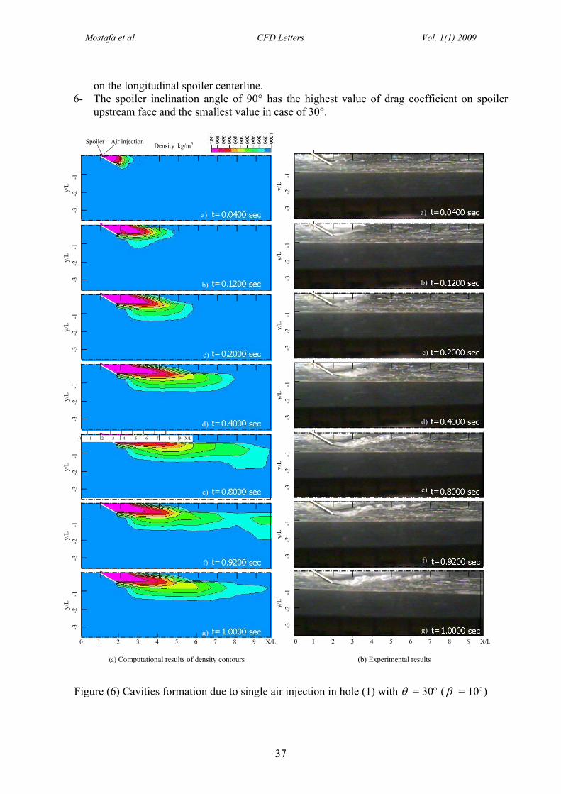
Figure (6) illustrates the cavities formation for spoiler inclination angle = 30 for a total time of 1 second starting from the injection of air. The numerical results demonstrate that the cavity formation has mainly three stages. First, a cavity starts to grow at the wake of the spoiler body as shown in Figs. 6a-d. At the second stage, the cavity starts to split, Fig. 6f. Finally, the split cavity runs away at the third stage. The computational and experimental results show that there is a good matching of bubble formation except that the computational bubble has slow splitting and is not attached to the ship body, so, a layer of water was isolated between the bubble and the ship body,Figs. 6d-f. This may be due to the flow is computed as a laminar flow. The free surface module in the numerical code CFDRC is not compatible with the turbulent flow module.
For spoiler inclination angle = 60, Figure (7) shows the cavities formation. Similar to the previous case, the cavity formation passes through three stages. The growth of cavity at the wake of the spoiler body, Figs. 7a-d, the circulation of the flow inside the bubble, Figs. 7e-f, and finally the growth of cavity downstream and taking the final form at the third stage, Fig. 7g. Both the experimental and numerical results show that bubble formation is attached to the ship surface from the beginning and it is more stable than that for inclination angle = 30. Good matching between numerical and experimental results except the computational bubble shape has small dissimilarity and not flatted at bubble tail.
Figure (8) displays the cavities formation for spoiler inclination angle = 90. The main features observed from the numerical results are the attachment of cavity is to the ship surface from the starting of injection, the cavity takes a rectangular shape due to the perpendicular spoiler on the ship surface and gradual increase in the length of the cavity. However, the comparison with the experimental results reveals that the cavity height decreases from the free point of spoiler and flatten to ship surface downstream.
The static pressure contours around the spoiler, upstream and downstream spoiler faces for three inclination angles at time t = 1 second are demonstrated in Figure (9). For the spoiler inclination angle = 30, the static pressure contours downstream the spoiler shows the existence of different pressure regions due to the small angle of inclination. However, increasing this angle to = 60 one pressure region can be observed with extension beyond 7L downstream. Finally, the pressure contours for = 90 illustrate the mostly uniform static pressure downstream the spoiler. On the other hand, the static pressure distribution on the upstream and downstream faces of the spoiler illustrated in Fig. (9) shows an increase in static pressure on the front surface related to the increase in inclination angle of spoiler. Also, less pressure is observed on the three free edges of the

Experimental and Numerical Study of Spoiler Effect on Ship Stability: Effect of Spoiler Inclination Angle
36
spoiler. Meanwhile, the mean negative static pressure on the downstream face of spoiler increases.The total pressure contours around the spoiler in X-Y and X-Z planes, upstream and
downstream spoiler faces for three inclination angles at time t = 1 second are displayed in Figures(10, 11). It is demonstrated that the iso-total pressure contours at the spoiler downstream are approximately similar to the iso-density contours which indicated that modeling the two-phase flow field around a ship spoiler using three-dimensional Navier-Stokes with the Free Surface simulation in Piecewise Linear Interface Construction (PLIC) method is successful.
The major objective of this paper is the development of a controlling system of ship motions and speed. This system can not be verified without the determination of the moment around the fixation point. It is observed from the numerical results that the line of maximum pressure drop of spoiler face is its longitudinal centerline. The maximum of moment values for = 30 equals 4.124 N.m. For = 60, the maximum value of moment is 6.177 N.m while for = 90, the maximum value of moment is 6.81 N.m. Therefore, the moment around the 90 inclined spoiler fixation line is 1.651 times that around the 30 inclined spoiler and 1.1 times that around the 60inclined spoiler after 1 second.
Finally, the drag, heel moment and lift coefficients as a function of spoiler inclination anglefor = 10 and single injection in hole (1) are demonstrated in Figure (12). The effect of spoiler inclination angle on drag coefficient is high because of the produced total pressure on spoiler faces. Increasing of angle increases the total pressure on upstream face of spoiler and decreases it on downstream face. So, the drag coefficient is gradually increased with increasing of spoiler inclination angle. The heel moment coefficient variation with three different inclination angles = 30°, 60°, and 90° follows generally the trends of drag coefficient variation with inclination angle. Conversely, the lift coefficient decreases with the increase of spoiler inclination angle. The lift coefficient is zero for spoiler with angle = 90°.
7. Conclusion
The study of the transient flow around ship spoiler with injection of exhaust gases or air reveals that the three main parameters that have influence on the flow characteristics are the spoiler inclination angle, floor angle and the position of air injection holes. In this paper the effect of spoiler inclination angle is presented for floor angle = 10 and single injection in hole (1). The main conclusions are summarized:
1- The ship spoiler has a strong wake effect with gas injection, which can control the ship oscillation.
2- For inclination angle = 30, the cavity formation has mainly three stages: growth of cavity at the wake of the spoiler, start of cavity split and collapsing of the splitting cavity.
3- The iso-total pressure contours at the spoiler downstream are approximately similar to the iso-density contours which indicated that modeling the two-phase flow field around a ship spoiler using three-dimensional Navier-Stokes with the Free Surface simulation in Piecewise Linear Interface Construction (PLIC) method is successful.
4- The comparison between the numerical and experimental results shows a good matching of bubble formation in case of spoilers with 60 and 90 inclination angles except that the computational bubble shape has small dissimilarity and not flatted at bubble tail, and the computational bubble shape has slow splitting and is not attached to the ship body in case of spoiler with 30 inclination angle. This may be attributed to the laminar flow computation without including turbulence effects
5- The moment around the 90 inclined spoiler fixation line is 1.651 times that around the 30inclined spoiler and 1.1 times that around the 60 inclined spoiler after 1 second and acting
Mostafa et al. CFD Letters Vol. 1(1) 2009
37
on the longitudinal spoiler centerline.6- The spoiler inclination angle of 90° has the highest value of drag coefficient on spoiler
upstream face and the smallest value in case of 30°.
-3
-
2
-1
y/
L
-3
-
2
-1
y/
L
-3
-
2
-1
y/
L
-3
-
2
-1
y/
L
-3
-
2
-1
y/
L
-3
-
2
-1
y/
L
-3
-
2
-1
y/
L
(a) Computational results of density contours (b) Experimental results
Density kg/m3
0 1 2 3 4 5 6 7 8 9 X/L
Spoiler Air injection
-3
-
2
-1
y/
L-3
-2
-1
y/L
-3
-2
-1
y/
L-3
-2
-1
y/L
-3
-2
-1
y/
L-3
-2
-1
y/L
-3
-
2
-1
y/
L
a)
b)
c)
d)
e)
f)
g) 0 1 2 3 4 5 6 7 8 9 X/L 0 1 2 3 4 5 6 7 8 9 X/L
a)
b)
c)
d)
e)
f)
g)
Figure (6) Cavities formation due to single air injection in hole (1) with = 30 ( = 10)

Experimental and Numerical Study of Spoiler Effect on Ship Stability: Effect of Spoiler Inclination Angle
38
-3
-
2
-1
y/
L
-3
-
2
-1
y/
L
-3
-
2
-1
y/
L
-3
-
2
-1
y/
L
-3
-
2
-1
y/
L
-3
-
2
-1
y/
L
-3
-
2
-1
y/
L
-3
-
2
-1
y/
L-3
-2
-1
y/L
-3
-
2
-1
y/
L-3
-2
-1
y/L
-3
-
2
-1
y/
L-3
-2
-1
y/L
-3
-
2
-1
y/
L
(a) Computational results of density contours (b) Experimental results
Density kg/m3
a)
b)
c)
d)
e)
f)
g) 0 1 2 3 4 5 6 7 8 9 X/L 0 1 2 3 4 5 6 7 8 9 X/L
a)
b)
c)
d)
e)
f)
g)
Spoiler Air injection
Figure (7) Cavities formation due to single air injection in hole (1) with = 60 ( = 10)

Mostafa et al. CFD Letters Vol. 1(1) 2009
39
-3
-
2
-1
y/
L-3
-2
-1
y/L
-3
-
2
-1
y/
L-3
-2
-1
y/L
-3
-
2
-1
y/
L-3
-2
-1
y/L
-3
-
2
-1
y/
L
-3
-
2
-1
y/
L-3
-2
-1
y/L
-3
-
2
-1
y/
L-3
-2
-1
y/L
-3
-
2
-1
y/
L-3
-2
-1
y/L
-3
-
2
-1
y/
L
Density kg/m3
(a) Computational results of density contours (b) Experimental results
Spoiler Air injection
a)
b)
c)
d)
e)
f)
g) 0 1 2 3 4 5 6 7 8 9 X/L 0 1 2 3 4 5 6 7 8 9 X/L
a)
b)
c)
d)
e)
f)
g)
Figure (8) Cavities formation due to single air injection in hole (1) with = 90 ( = 10)

Experimental and Numerical Study of Spoiler Effect on Ship Stability: Effect of Spoiler Inclination Angle
40
1) Front view 2) Upstream face 3) Downstream face(a) = 30 Static pressure N/m2
-3
-
2
-1
y/
L
0
-1y/
L
0
-1y/
L
(b) = 60
-3
-
2
-1
y/
L
0
-1y/
L
0
-1y/
L
(c) = 90
-3
-
2
-1
y/
L
0
-1y/
L
0
-1y/
L
1 Z/L0 1 Z/L0
Figure (9) Static pressure around spoiler at different and t = 1 sec.( = 10 and single air injection in hole (1))
(1) Front view (2) Upstream face (3) Downstream face(a) = 30
-3
-
2
-1
y/
L
0
-1y/
L
0
-1y/
LTotal pressure N/m2
(b) = 60 0
-1y/
L
0
-1y/
L
-3
-
2
-1
y/
L
(c) = 90
-3
-
2
-1
y/
L
0
-1y/
L
0
-1y/
L
1 Z/L0 1 Z/L0
Figure (10) Total pressure around spoiler at different and t = 1 sec.( = 10 and single air injection in hole (1))
0 1 2 3 4 5 6 7 8 9 X/L
0 1 2 3 4 5 6 7 8 9 X/L

Mostafa et al. CFD Letters Vol. 1(1) 2009
41
- 4
-
3
-2
-1
0
z/
L
Total pressure N/m2Injection holeSpoiler
- 4
-
3
-2
-1
0
z/
L
(a) = 30 (b) = 60
Figure (11) Total pressure around spoilerat different and t = 1 sec (at X-Z).
( = 10 and single air injection in hole (1))
- 4
-
3
-2
-1
0
z/
L
0 1 2 3 4 5 6 7 8 9 X/L
(c) = 90
0 30 60 90 120
(o)
0
2
4
6
8
CD
,CL
,C
CD
CL
C
Figure (12) Drag, heel moment and lift coefficients against different spoiler inclination angles after 1 sec.
NomenclatureA spoiler area, m2
dc local cell “dimension” (or length-scale), mF liquid volume fraction, dimensionlessL spoiler length, mMφ heel moment, N.mP fluid static pressure, N/m2
Pt total pressure, N/m2
u,v,w velocity in x, y, z respectively, m/s
cv local velocity vectorVcut volume of the cell truncated by the cutting plane, m3
Vc volume of the whole cell, m3
W spoiler width, mGreek ∆t physical time step, secondtc maximum time step that can be taken in cell, second

Experimental and Numerical Study of Spoiler Effect on Ship Stability: Effect of Spoiler Inclination Angle
42
dynamic viscosity, kg/m.s surface tension between the two fluids, N/mSuffixes1 value of the fluid property (air)2 value of the fluid property (water)D dragL liftφ heel moment
References
[1] Clark, I.C. The Management of Merchant Ship Stability, Trim & Strength. The Nautical Institute. 2002.
[2] Madavan, N.K., Deutsch, S. and C.L. Merkle, Measurements of local skin friction in a microbubble-modified turbulent boundary layer. Journal of Fluid Mechanics, 1984. 27:pp. 356-363.
[3] Murai, Y., H. Fukuda, Y. Oishi, Y. Kodama, and F. Yamamoto, Skin friction reduction by large air bubbles in a horizontal channel flow. International Journal of Multiphase Flow, 2007. 33: pp. 147-163.
[4] Walsh, M.J. and A.M. Lindemann, Optimization and application of riblets for turbulent drag reduction. AIAA Paper No. 84-0347, 1984.
[5] Fukuda, K., J. Tokunaga, T. Nobunaga, T. Nakatani, T. Iwasaki, and Y. Kunitake. Frictional drag reduction with air lubricant over a super-water-repellent surface. Journal of Marine Science and Technology, 2000. 5: pp. 123-130.
[6] Soper, R.R., A.H. Nayfeh, and D.T. Mook, Control of rolling ships by hull-mounted spoilers. Fourth Semi-Annual Meeting- MURI, Nonlinear Active Control of Dynamical Systems. Blacksburg, VA, 1998.
[7] Owis, F., A.H. Nayfeh, and D.T. Mook, Control of roll motion using a system of spoilers.Seventh Semi-Annual Meeting– MURI- Nonlinear Active Control of Dynamical Systems, Blacksburg, VA, USA, 2000.
[8] Mostafa, N.H., Computed transient supercavitating flow over a projectile. Mansoura Engineering Journal, MEJ, 2001. 26(2): pp. M79-M91.
[9] Mostafa, N.H., Flow around ship spoiler. Mansoura Engineering Journal, MEJ, 2001. 26(3):pp. M1-M14.
[10] Mostafa, N.H., Numerical and experimental analysis of transient 2D flow around ship spoiler. Mansoura Engineering Journal, MEJ, 2003. 28(1): pp. M1-M19.
[11] Hirt, C.W. and B.D. Nichols, Volume of Fluid (VOF) method for the dynamics of free boundaries. Journal of Computational Physics, 1981. 39: pp. 201-225.
[12] Rider, W.J., D.B. Kothe, S.J. Mosso, J.H. Cerrutti, and J.I. Hochstein, Accurate solution algorithms for incompressible multiphase fluid flows. AIAA Paper 95-0699, 1995.
[13] Noh, W.F. and P.R. Woodward, SLIC (Simple Line Interface Method). in A.I. van de Vooren and P.J. Zandbergen, (Editors), Lecture Notes in Physics, 1976. 59: pp. 330-340.
[14] Kothe, D.B., W.J. Rider, S.J. Mosso, and J.S. Brock, Volume tracking of interfaces having surface tension in two and three dimensions. AIAA Paper 96-0859, 1996.
[15] White, F.M. Fluid Mechanics. Fourth Edition, WCB McGraw-Hill. 2001.[16] CFDRC. CFD-ACE+ Theory and Users’ Manuals. CFD Research Corporation, Huntsville,
Al., USA. 2004.