Methodwaveletformultifractalimageanalisis Anisotropic Isotropic
Vietrock2015 an ISRM specialized conference Vietrock2015 12-13March 2015, Hanoi, Vietnam
Experimental and Numerical Anisotropic Rock Mechanics
Ki-Bok Min*, Hanna Kim and Bona Park
Department of Energy Resources Engineering, Seoul National University, Seoul, Korea
Abstract
Characterization and numerical modeling of anisotropic rock is a longstanding difficulty in rock mechanics. This paper provides overview anisotropic rock mechanics and introduces a series of experimental and numerical anisotropic rock mechanicsstudies. Experimental investigations are made on elastic, strength, thermal conductivity, seismic and permeability anisotropy of rock based on samples from directional coring system. Degrees of anisotropy in Asan Gneiss, Boryeong Shale and Yeoncheon Schist considered in this study are significant and have the possibility of producing errors in engineering geology applications when anisotropy is not considered.The applicability of transversely isotropic model to the chosen rocks was quantitatively investigated by comparing the apparent elastic moduli with the theoretical apparent elastic moduli predicted by tensorial transformation of compliance matrix.
For numerical stud, the smooth joint was employed in a discrete element method (DEM) code to represent a single set of weak cohesive planes in order to model the transversely isotropic rock. Systematic verification was conducted against the analytical solutions in terms of anisotropic elastic and strength behaviors. The developed model was compared with laboratory observations of three rock types leading to good agreements. Bonded-particle DEM modeling successfully captured the failure patterns observed in anisotropic in which weak planes play a significant role. The developed numerical model was upscaled to large-scale foundations problems subjected to surface line load. The study achieved reasonable agreements both for isotropic and anisotropic solutions. The results demonstrate that bonded-particle DEM with embedded smooth joints can model the equivalent anisotropic medium and it has potential to be applied to problems of larger engineering problems in which anisotropy is important.
Keywords:Rock Anisotropy, Transverse Isotropy, Compliance Matrix, Discrete Element Method
1. Introduction
Anisotropy is one of the most distinct features that must be considered in rock engineering whether
it is applied in civil, mining, geoenvironmental, or petroleum engineering disciplines. Many rocks
have anisotropic characteristics, i.e., their mechanical, thermal, seismic, and hydraulic properties vary
with direction, and engineering applications that do not consider the anisotropic behavior of rock
produce errors of differing magnitudes, depending on the extent of rock anisotropy (e.g., Amadei,
1997). Therefore, anisotropy has been a long-standing issue in rock engineering, beginning in the
early developmental stages of rock mechanics. Anisotropic characteristics generally originate from
the mineral foliation in metamorphic rocks, stratification in sedimentary rocks, and discontinuities in
the rock mass.Rock anisotropy is important for in situ stress measurements especially for the
overcoring method in which the constitutive relation of rock plays an important role (Amadei, 1997),
displacement control in rock, and the development of excavation damage occurring during
Vietrock2015 an ISRM specialized conference Vietrock2015 12-13March 2015, Hanoi, Vietnam
underground construction. When the equivalent continuum approach is used for regularly-fractured
rock masses, anisotropy must be considered because it can be quite significant due to the major
deformations along the discontinuities. Thus, it is important to be aware of the degree of mechanical
rock anisotropy, which is generally defined by the elastic modulus ratio, in order to decide whether it
is necessary and relevant to consider anisotropy before certain operations begin (Cho et al., 2012).
The term 'anisotropy' is somewhat misleading in that the prefix 'an-' gives an impression that it is a
special case of 'isotropy'. However, the anisotropic elastic behavior of material, which is defined by
21 independent elastic constants, is indeed the most general case and includes no assumption of
symmetry. Isotropy, then, is the most special case, since it is defined by only two independent elastic
constants after the assumption of complete symmetry is made (Lekhnitskii, 1963). If the internal
composition of a material possesses symmetry of any kind, then symmetry can be observed in its
elastic properties. While there are many forms of elastic symmetry, the most relevant models for
applications involving rock mechanics are the transversely isotropic models. The stratification,
foliation, and discontinuity planes, which are encountered frequently in rock mechanics applications,
can be viewed as the transversely isotropic plane.
This paper presents some of recent research development for experimental and numerical
anisotropic rock mechanics. Anisotropic elastic, strength, thermal, seismic and permeability behaviors
are investigated for experimental study and numerical study is presented with focus on discrete
element application.
2. Theoretical background
The constitutive relation for general linear elasticity can be expressed as follows;
klijklij S (1)
whereijand kl are stress and strain tensors of a second order rank and Sijkl is the compliance tensor
of a fourth order rank, involving 21 independent.
Since Sijkl is a fourth order tensor, its rotational transformation can be also defined by the following
mapping operations (e.g., Ting, 1991)
mnpqlpkpjnimijkl SS (2)
Where Sijkl and Smnpq are the compliance tensors in the transformed and the original axes,
respectively, and im is direction cosines representing rotational operations. Eq. (2) is mathematically
elegant but not convenient for practical calculations because it involves fourth order tensor operations.
The following mapping operation with a 6 by 6 matrix for the transformation of compliance matrix is
introduced to simplify the operations (Lekhnitskii, 1963)

Vietrock2015 an ISRM specialized conference Vietrock2015 12-13March 2015, Hanoi, Vietnam
ij mn mi njS S q q (3)
whereSijis the compliance matrix in the transformed axes and Smn is the one in the original axes,
respectively.
Thermal conductivity and permeability obey the rotational transformation rules as a second-order
tensor. The tensor of the anisotropic thermal conductivity and permeability is formulated as Eq. (4)
with respect to the rotation of the axes (Carslaw and Jaeger, 1959; Bear, 1971).
pq pi qj ijk k (4)
Where kij and kpq are the thermal conductivity or permeability tensors in the original and rotated
axes, respectively, and βpiand βqjare the direction cosines.
Constitutive equation of the transversely isotropic rock can be expressed as follows in a matrix
form;
1 '0 0 0
'
' 1 '0 0 0
' ' '
' 10 0 0
'
10 0 0 0 0
'
2(1 )0 0 0 0 0
10 0 0 0 0
'
x x
y y
z z
yz yz
zx zx
xy xy
E E E
E E E
E E E
G
E
G
(5)
In the above compliance matrix, there are five independent elastic constants. E and E’ are the elastic moduli in the plane of transverse isotropy and in a direction normal to it, respectively. The terms ν and ν’are the Poisson’s ratios that characterize the lateral strain response in the plane of transverse isotropy to a stress acting parallel and normal to it, respectively. The term G’ is the shear modulus in the plane normal to the plane of transverse isotropy.
The strength of fractured rock with through going fracture can be expressed as a function of confining stress (σ3), friction angle (ф), cohesion (C) of the rock mass, and the inclined angle of a single set of discontinuities (β), as shown below (Jaeger et al., 2007):
31 3
2 ( tan )
(1 tan cot ) sin 2
C
(6)
3. Experimental anisotropic rock mechanics 3.1 Experimental setup
Coring a block with angles of 0, 15, 30, 45, 60, 75, and 90 degrees with respect to the transverse
isotropic plane by using our laboratory-scale directional coring system (Fig. 1), cylindrical samples are obtained for anisotropic test for mechanical, thermal, seismic and permeability behavior (Cho et al., 2012; Kim et al., 2012, Yang et al., 2013). Samples with 70 mm in length and 38 mm in diameter were used for the mechanical and seismic experiments and samples with 25.4 mm in length and 7 mm in diameter were used for thermal conductivity test.

Vietrock2015 an ISRM specialized conference Vietrock2015 12-13March 2015, Hanoi, Vietnam
Fig. 1. Directional coring system and schematic of anisotropic rock samples (Cho et al., 2012).
3.2 Mechanical, thermal, seismic and hydraulic behavior of anisotropic rock
The experiments were conducted on three rock types, i.e., Asan gneiss, Boryeong shale, and Yeoncheonschist for mechanical, seismic and thermal properties, and Berea sandstone for permeability measurement.Except sandstone, samples showed a clear evidence of transverse isotropy due to the arrangements of some mineral particles as observed (Cho et al., 2012). Asan gneiss is biotite gneiss consisting of plagioclase, hornblende, quartz, and biotite. Flat minerals are arrayed parallel to the foliation plane.Boryeong shale shows flakes of clay minerals and mica that are aligned parallel tothe bedding.Yeoncheon schist has schistosity, in which the platy minerals, such as feldspar and mica, are aligned with the schistose plane. The gneiss and the shale were unweathered, fresh rock with very few visible microcracks. However, the schist had a number of microcracks.
Fig. 2shows the variations in the elastic moduli, P-wave velocity, and thermal conductivity with respect to the anisotropy angle in Asan gneiss, Boryeong shale, and Yeoncheon schist. Each curve in graph implies the predicted value based on tensorial transformation for transversely isotropic model (elastic moduli, thermal conductivity) and approximated equation for transversely isotropic model (P-wave velocity). The right axis of each graph in Fig. 2 indicates the normalized value by the average minimum one.In general, variations of the mechanical, seismic, and thermal properties showed similar trends with anisotropy angle. The maximum values of all three properties occurred in the direction parallel to the isotropic plane, and the minimum value occurred in the direction perpendicular to the isotropic plane. The exception was the elastic moduli of Asan gneiss, which had a minimum value at an inclined angle of 45°. It is noted that minimum elastic modulus is often observed at around this angle due to the low shear stiffness of foliation planes or fracture planes in case of equivalent continuum model (Min and Jing, 2003).

Vietrock2015 an ISRM specialized conference Vietrock2015 12-13March 2015, Hanoi, Vietnam
Fig. 2. Young’s modulus, P-wave velocity and thermal conductivity in different directions (Kim et al., 2012).
Fig. 3. Permeability of Berea sandstone in different directions (Yang et al., 2013).
The anisotropy ratios of the elastic moduli parallel and perpendicular to the isotropic planes (E/E')
for Asan gneiss, Boryeong shale, and Yeoncheon schist were determined to be 1.3, 2.1, and 3.4, respectively. Fig. 2shows the predicted elastic moduli based on the tensorial transformation of the compliance matrix based on the assumption that the rocks tested in this study are transversely isotropic materials. The anisotropy ratios of maximum to minimum uniaxial compressive strength were 2.6, 2.6 and 18.6 for Asan gneiss, Boryeong shale and Yeoncheon schist, respectively. The anisotropy ratios of maximum to minimum tensile strength determined by Brazilian Tensile test were 3.2, 2.2 and 7.1 for Asan gneiss, Boryeong shale and Yeoncheon schist, respectively (Cho et al., 2012). The anisotropy ratios of thermal conductivity parallel to and perpendicular to isotropic planes, (K (90°) /K (0°)), were 1.4 for Asan gneiss, 2.1 for Boryeong shale, and 2.5 for Yeoncheon schist. The P-wave velocity anisotropy ratio (VP (90°)/VP (0°)) was 1.2 for Asan gneiss, 1.5 for Boryeong shale, and 2.3 for Yeoncheon schist. The correlations between elastic moduli, P-wave velocities, and thermal conductivities were evident, even though there were some outliers. The best correlations were observed between thermal conductivities and P-wave velocities. There were good correlations between the elastic moduli and thermal conductivities as well as betweenthe elastic moduli and P-wave velocities for Boryeong shale and Yeoncheon schist. Asan gneiss showed poorest correlations due to more heterogeneous samples and the fact that the angle for minimum elastic moduli did not match with those for minimum P-wave velocities and thermal conductivities.
Five independent elastic constants of transversely isotropic rocks were determined using the strain measurements obtained from specimens having different coring directions (Cho et al., 2012). The applicability of transversely isotropic model to the chosen rocks was quantitatively investigated by comparing the apparent elastic moduli with the theoretical apparent elastic moduli predicted by tensorial transformation of compliance matrix. The mean prediction error (MPE) defined as the average relative difference between measured and predicted elastic moduli were lower than 17%, which indicates that transversely isotropic model is a reasonable assumption for the rock types chosen in this study (Cho et al., 2012). The extent of anisotropy observed in this study was significant and had the possibility of producing errors in engineering geology applications when anisotropy is not considered.
Fig. 3 shows the anisotropic permeability measured in Berea sand stone, in which degree of anisotropy can be larger than 1.5 even in sandstone which does not have clear visual anisotropy (Yang et al., 2013). Characterization of anisotropy through X-ray CT scanning system turned out to be a useful option as discussed by Yun et al. (2013). 4. Numerical anisotropic rock mechanics 4.1 Modeling methodology and verification
The results presented in this paper is obtained using PFC code (Itasca, 2008) which is a bonded-particle Discrete Element Method (DEM) defined as a dense packing of non-uniform sized circular or spherical particles joined at their contact points with parallel bond (Potyondy and Cundall, 2004). The calculation of particle movements is governed by Newton’s second law of motion and a
Vietrock2015 an ISRM specialized conference
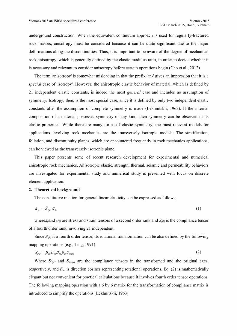
force-displacement law. This DEM modeling is effective in anisotropic rock modeling since it does not require pre-defined macroscopic failure criteria which can be very hard, if not impossible, to obtained especially in anisotropic case. The key conceptual idea of the current study is to include weak cohesive planes using a smooth joint model by assigning relatively larger cohesion compared to joints or fractures (Park and Min, 2015a, b)smooth interface by assigning new bonding models that have pre2011). Once the smooth joint, which consists of newlyand shear stiffness, friction coefficient, dilation angle, tensile strength, and cohesion, is created, pre-existing parallel bonds are deleted and replacedsamples made for DEM modeling.
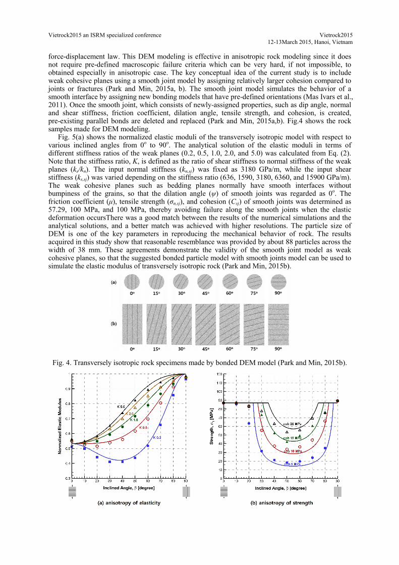
Fig. 5(a) shows the normalized elastic moduli of the various inclined angles from 0o
different stiffness ratios of the weak planes (0.2, 0.5, 1.0, 2.0, and 5.0) was calculated from Eq. (2). Note that the stiffness ratio, K, is defined as the ratio of shear stiffness to normal stiffness of the weak planes (ks/kn). The input normal stiffness (stiffness (ks,sj) was varied depending on the stiffness rThe weak cohesive planes such as bedding planes normally have smooth interfaces without bumpiness of the grains, so that the dilation angle (friction coefficient (μ), tensile strength (57.29, 100 MPa, and 100 MPa, thereby avoiding failure along the smooth joints when the elastic deformation occursThere was a good match between the results of the numerical analytical solutions, and a better match was achieved with higher resolutions. The particle size of DEM is one of the key parameters in reproducing the mechanical behavior of rock. The results acquired in this study show that reasonablewidth of 38 mm. These agreements demonstrate the validity of the smooth joint model as weak cohesive planes, so that the suggested bonded particle model with smooth joints model can be used to simulate the elastic modulus of transversely isotropic rock
Fig. 4. Transversely isotropic rock specimens made by
Vietrock2015 an ISRM specialized conference 12-13March
displacement law. This DEM modeling is effective in anisotropic rock modeling since it does defined macroscopic failure criteria which can be very hard, if not impossible, to
in anisotropic case. The key conceptual idea of the current study is to include weak cohesive planes using a smooth joint model by assigning relatively larger cohesion compared to
(Park and Min, 2015a, b). The smooth joint model simulates the behavior of a smooth interface by assigning new bonding models that have pre-defined orientations (Mas Ivars et al., 2011). Once the smooth joint, which consists of newly-assigned properties, such as dip angle, normal
oefficient, dilation angle, tensile strength, and cohesion, is created, existing parallel bonds are deleted and replaced (Park and Min, 2015a,b). Fig.4 shows the rock
samples made for DEM modeling. Fig. 5(a) shows the normalized elastic moduli of the transversely isotropic model with respect to
o to 90o. The analytical solution of the elastic moduli in terms of different stiffness ratios of the weak planes (0.2, 0.5, 1.0, 2.0, and 5.0) was calculated from Eq. (2).
, is defined as the ratio of shear stiffness to normal stiffness of the weak ). The input normal stiffness (kn,sj) was fixed as 3180 GPa/m, while the input shear ) was varied depending on the stiffness ratio (636, 1590, 3180, 6360, and 15900 GPa/m).
The weak cohesive planes such as bedding planes normally have smooth interfaces without bumpiness of the grains, so that the dilation angle (ψ) of smooth joints was regarded as 0
), tensile strength (σn,sj), and cohesion (Csj) of smooth joints was determined as 57.29, 100 MPa, and 100 MPa, thereby avoiding failure along the smooth joints when the elastic deformation occursThere was a good match between the results of the numerical analytical solutions, and a better match was achieved with higher resolutions. The particle size of DEM is one of the key parameters in reproducing the mechanical behavior of rock. The results acquired in this study show that reasonable resemblance was provided by about 88 particles across the width of 38 mm. These agreements demonstrate the validity of the smooth joint model as weak cohesive planes, so that the suggested bonded particle model with smooth joints model can be used to
late the elastic modulus of transversely isotropic rock (Park and Min, 2015b)
ersely isotropic rock specimens made by bonded DEM model (Park and Min, 2015b)
Vietrock2015 3March 2015, Hanoi, Vietnam
displacement law. This DEM modeling is effective in anisotropic rock modeling since it does defined macroscopic failure criteria which can be very hard, if not impossible, to
in anisotropic case. The key conceptual idea of the current study is to include weak cohesive planes using a smooth joint model by assigning relatively larger cohesion compared to
es the behavior of a defined orientations (Mas Ivars et al.,
assigned properties, such as dip angle, normal oefficient, dilation angle, tensile strength, and cohesion, is created,
Fig.4 shows the rock
transversely isotropic model with respect to . The analytical solution of the elastic moduli in terms of
different stiffness ratios of the weak planes (0.2, 0.5, 1.0, 2.0, and 5.0) was calculated from Eq. (2). , is defined as the ratio of shear stiffness to normal stiffness of the weak
) was fixed as 3180 GPa/m, while the input shear atio (636, 1590, 3180, 6360, and 15900 GPa/m).
The weak cohesive planes such as bedding planes normally have smooth interfaces without ) of smooth joints was regarded as 0o. The
) of smooth joints was determined as 57.29, 100 MPa, and 100 MPa, thereby avoiding failure along the smooth joints when the elastic deformation occursThere was a good match between the results of the numerical simulations and the analytical solutions, and a better match was achieved with higher resolutions. The particle size of DEM is one of the key parameters in reproducing the mechanical behavior of rock. The results
resemblance was provided by about 88 particles across the width of 38 mm. These agreements demonstrate the validity of the smooth joint model as weak cohesive planes, so that the suggested bonded particle model with smooth joints model can be used to
(Park and Min, 2015b).
(Park and Min, 2015b).

Vietrock2015 an ISRM specialized conference Vietrock2015 12-13March 2015, Hanoi, Vietnam
Fig. 5. Verification of elastic and strength anisotropy using DEM. (a) Normalized elastic modulus in transversely isotropic rock model (symbol) with different stiffness ratios (K) is compared to that of
the analytical solution (line). (b) Strength in the transversely isotropic rock model (symbol) is compared to that of the analytical solution (line) (Park and Min, 2015b)
Furthermore, the DEM model can capture strength anisotropy to a reasonable extent as seen Fig.5
(b). The strength trends of the analytical solution indicated that a smaller friction angle or cohesion makes the curve wider and the minimum strength smaller. Since the bonded particle model is not a continuum, a perfect match between the analytical and numerical models was not expected for strength variation. Some discrepancies are inevitably noticed as a form of transition between failures due to the creation of a new fracture, and the DEM model may be more realistic in this regard than the analytical model.
4.2 Numerical results– validation against laboratory results
Three different types of transversely isotropic rock (Asan gneiss, Boryeong shale and Yeoncheon
schist) were reproduced as numerical models by assigning the microparameters of the bonded particle model and the smooth joint model. In the numerical model, there are about 88 balls across 38 mm width of the specimen. As a result of the calibration process, macroproperties including elastic modulus, uniaxial compressive strength and Brazilian tensile strength of the numerical experiments were compared with those of the laboratory tests as presented in Fig. 6. The squares indicate the laboratory test results, and the solid lines indicate the numerical test results. In the laboratory experiment, UCS of the specimen with the vertical weak planes was greater than the value of the specimen with horizontal weak planes although only identical UCSs are possible in the analytical solutions. It appears that rock matrix between layers also has a certain directional characteristics with stronger strength in the direction parallel to the layers. As this second-order anisotropy present in rock matrix was not considered in numerical model, current DEM model cannot adequately address this strength difference observed in direction parallel and perpendicular to the weak planes. Only a shoulder-type form of strength variation predicting the equal strength parallel and perpendicular to the loading axis was observed in the numerical experiments. It appears that the DEM model captured the elastic and strength behavior of laboratory observation to a reasonable extent, given that the variation of the elastic and strength properties in the laboratory measurements fluctuated and did not necessarily follow the theoretical trends.
Failure mechanisms during uniaxial and tensile tests were analyzed by comparing the failure patterns observed during numerical and laboratory experiments. Failure patterns for the Brazilian tensile strength test investigated in the DEM model showed that the breakage of parallel bonds and smooth joints in the numerical model was represented as micro tensile and shear failures (Vervoort et al., 2014; Park and Min, 2015b).

Vietrock2015 an ISRM specialized conference Vietrock2015 12-13March 2015, Hanoi, Vietnam
Fig. 6 Comparison of elastic modulus, uniaxial compressive strength and Brazilian tensile strength from laboratory tests, and those from bonded-particle DEM modeling (Park and Min, 2015b)
4.3 Numerical results– upscaling to large scale foundation problem
DEM model is then upscaled to larger scale problem, e.g. foundation problem. In this study,
isotropic rock mass model of surface loading, a 2 x 2 m square model that contained 114,984 particles was used, and all boundaries were constrained except the upper boundary on which the surface line load was applied. A small piece of wall was generated on the upper boundary of the model in order to apply the surface line load. The stress distribution along the same distance line of isotropic rock mass model was compared to that of the numerical calculation, thereby obtaining the results shown in Fig. 7(a). In this model, the radial stress was calculated at the distance (r) of 0.4, 0.6, and 0.8 m from the applied line load, which is 10 MN/m (Park and Min, 2015a). Contact force induced by the applied surface loading is shown in the left, and the pressure bulbs of radial stress (σr) are presented in the right with respect to the distance (r) of 0.4, 0.6, and 0.8 m from the point of applied line load for the angle (θ) ranging from 0o to 180o. Three different solid lines and three different shapes of symbols indicate the results of the analytical solution and the numerical model, respectively. The measured stress in the numerical model was in good agreement with the value from the analytical solution. As the pressure bulb becomes larger, the magnitude of measured stress increases, meaning that the measured point is closer to the applied load (ρ). The closer the measured points are to the applied load, the more discrepancy is observed due to the higher magnitude of stress and gradient in the vicinity. This is because there were relatively fewer particles in the vicinity of the loading point, which resulted in a more heterogeneous stress distribution.

Vietrock2015 an ISRM specialized conference Vietrock2015 12-13March 2015, Hanoi, Vietnam
For the transversely isotropic rock mass model, smooth joints were inserted into the isotropic model in the same way that was introduced in the laboratory scale modeling. Three models with 0o, 60o, and 90o inclined angle of smooth joints were taken into account. In these transversely isotropic models, the radial stress was estimated under the same boundary and loading conditions as those employed in the isotropic rock mass model. As a result, the stress distribution in the numerical model and that in the analytical solution were compared, as illustrated in Fig. 7(b-d). The observations in transversely isotropic rock also showed a close match between the results of the numerical and analytical solutions. In particular, the developed bonded-particle DEM successfully captured the effect of the bedding planes in horizontal, inclined, and vertical directions on the stress distribution. Some discrepancies between the numerical and analytical solutions were observed close to the loading points, which was similar to the results of the isotropic model. As the distance from the applied load becomes shorter, fewer weak cohesive planes are embedded, which was not sufficient to simulate the equivalent anisotropic behaviors of rock mass. The large-scale DEM modeling of both isotropic and transversely isotropic rock mass matched well in accordance with the analytical solutions, which demonstrated that the developed model can estimate the stress distribution within the rock mass. Therefore, future work is suggested in relation to modeling the in situ scale fracturing process, such as borehole breakout or hydraulic fracturing in transversely isotropic rock formations.
Fig. 7. Contact force distribution in rock mass bonded-particle DEM model (top) and pressure bulbs derived from both bonded-particle DEM model and analytical solutions (below): (a) isotropic case, and (b-d) transversely isotropic cases with the inclined angles of 0o, 60o, and 90o, respectively (Park and Min, 2015a). 5. Conclusions
This paper provides brief overview of theoretical anisotropic rock mechanics and introduces a
series of experimental and numerical study applied to anisotropic rock mechanics. The importance of anisotropic rock mechanics as a general behavior is emphasized.
For each rock types, three sets of seven cylindrical specimens cored with angles of 0, 15, 30, 45, 60, 75, and 90 degrees with respect to transverse isotropic planes were obtained by using laboratory directional coring system established for this study. Experimental investigation of elastic, strength and thermal conductivity anisotropy of Asan gneiss, Boryeong shale and Yeoncheon schist in Korea showed a clear evidence of transverse isotropy. The anisotropy ratios of elastic modulus parallel to and perpendicular to isotropic planes (E/E') were determined to be 1.3, 2.1 and 3.4 for Asan gneiss,
(a) (c) (d) (b)

Vietrock2015 an ISRM specialized conference Vietrock2015 12-13March 2015, Hanoi, Vietnam
Boryeong shale and Yeoncheon schist, respectively.The anisotropy ratios of maximum to minimum uniaxial compressive strength were 2.6, 2.6 and 18.6 for Asan gneiss, Boryeong shale and Yeoncheon schist, respectively. The anisotropy ratios of maximum to minimum tensile strength determined by Brazilian Tensile test were 3.2, 2.2 and 7.1 for Asan gneiss, Boryeong shale and Yeoncheon schist, respectively.The applicability of transversely isotropic model to the chosen rocks was quantitatively investigated by comparing the apparent elastic moduli with the theoretical apparent elastic moduli predicted by tensorial transformation of compliance matrix.
Bonded-particle discrete element method with embedded smooth joints was applied to model the mechanical behavior of transversely isotropic rock with systematic verifications and extensions to laboratory and upscaled problems. The bonded particle model was adopted to construct isotropic rock without weak planes, which was calibrated based on elastic modulus and strengths that have the least effect of weak planes. Then, the smooth joint model was inserted to create the weak cohesive planes to simulate the behavior of the equivalent anisotropic continuum.Variation of the normalized elastic modulus in the numerical model with various stiffness ratios was in good agreement with the results of the analytical solutions.
The calibration results of the bonded-particle DEM model were compared well with those of the laboratory test. The results showed that the bonded-particle DEM model with embedded smooth joints was able to simulate the transversely isotropic rock.
Application of DEM to a larger scale anisotropic problem with stress distribution from the applied surface loading was compared to the results of the analytical solution, resulting in good agreement. Consequently, the bonded-particle DEM model of transversely isotropic rock mass model, of which the mechanical behaviors obey the analytical solutions, was able to model the in situ scale deformation and fracturing process.
This study paves the way for further applications, and the bonded-particle DEM model can be further employed effectively in rock engineering applications, particularly in transversely isotropic rock formations. Acknowledgements
This work was supported by the New & Renewable Energy Technology Development Program of the Korea Institute of Energy Technology Evaluation and Planning (KETEP) through a grant that was funded by the Ministry of Trade, Industry & Energy, Republic of Korea (No. 20133030000240). The work presented in this keynote paper is compilation of the previous publications and the contribution from our coauthors are greatly acknowledged especially Jung-Woo Cho of Korea Institute of Industrial Technology. References Amadei, B.,1996, Importance of anisotropy when estimating and measuring in situ stresses in rock,Int.
J. Rock Mech. Min. Sci.&Geomech. Abstr.,33(3), 293-325. Bear, J., 1972, Dynamics of fluids in porous media, Dover, p.764. Carslaw, H.S., Jaeger, J.C., 1959, Conduction of Heat in Solids, second ed, Clarendon Press. Cho, J.W., Kim, H., Jeon, S. and Min, K.B., 2012, Deformation and strength anisotropy of Asan
gneiss, Boryeong shale, and Yeoncheon schist,Int.J.Rock Mech.&Min.Sci.,50(12), 158-169. Itasca Consulting Group Inc, 2008, PFC 2D (Particle Flow Code in 2 Dimensions), Version 4.0,
Minneapolis, ICG. Jaeger, J.C., Cook, N.G.W. and Zimmerman, R.W., 2007, Fundamentals of Rock Mechanic, fourth
ed., Blackwell. Kim, H., Cho, J.W., Song, I. and Min, K.B., 2012, Anisotropy of elastic moduli, P-wave velocities,
and thermal conductivities of Asan Gneiss, Boryeong Shale, and Yeoncheon Schist in Korea, Eng. Geol., 147-148, 68-77.
Lekhnitskii, S.G., 1963, Theory of elasticity of an anisotropic body, Holden-Day. Mas Ivars, D., Pierce, M.E., Darcel, C., Reyes-Montes, J., Potyondy, D.O., Young,P.R. andCundall,
P.A., 2011, The synthetic rock mass approach for jointed rock mass modelling,Int.J.Rock Mech.&Min.Sci., 48(2),219-44.
Min, K.B. and Jing, L., 2003, Numerical determination of the equivalent elastic compliance tensor for fractured rock masses using the distinct element method, Int.J.Rock Mech.&Min.Sci.,40(6), 795-816.
Vietrock2015 an ISRM specialized conference Vietrock2015 12-13March 2015, Hanoi, Vietnam
Park, B. and Min, K.B., 2015, Discrete element modeling of transversely isotropic rock applied to foundation and borehole problems, 13rd ISRM Congress, Vancouver, Canada
Park, B. and Min, K.B., 2015,Bonded-Particle Discrete Element Modeling of Mechanical Behavior of Transversely Isotropic Rock, 2015, under review.
Potyondy, D.O. and Cundall, P.A., 2004, A bonded-particle model for rock. Int.J.Rock Mech.&Min.Sci., 41(8), 1329-64.
Ting, T.C.T., 1996, Anisotropic Elasticity – Theory and Applications, Oxford University Press, p.570. Vervoort, A., Min, K.B., Konietzky, H., Cho, J.W., Debecker, B., Dinh, Q.D., Fruhwirt, T.
andTavalali, A., 2014, Failure of transversely isotropic rock under Brazilian test conditions, Int.J.Rock Mech.&Min.Sci., 70:343-352.
Yang, H.Y., Kim, H., Kim, K., Kim, K.Y. and Min, K.B., 2013, A study of locally changing pore characteristics and hydraulic anisotropy due to bedding of porous sandstone, Tunnel Undergr Space, 23(3), 228-240.
Yun, T.S., Jeong, Y.J., Kim, K.W. and Min, K.B., 2013, Evaluation of rock anisotropy using 3D X-ray computed tomography, EngGeol, 163, 11-19.