Experimental and CFD investigations into slamming of small, high speed craft Dominic Hudson, Simon...
27
Experimental and CFD investigations into slamming of small, high speed craft Dominic Hudson, Simon Lewis, Stephen Turnock ONR Hull slamming workshop, Caltech 17-18 th February 2009
-
Upload
karson-kings -
Category
Documents
-
view
217 -
download
0
Transcript of Experimental and CFD investigations into slamming of small, high speed craft Dominic Hudson, Simon...
Experimental and CFD investigations into slamming of small, high speed craft
Dominic Hudson, Simon Lewis, Stephen Turnock
ONR Hull slamming workshop, Caltech
17-18th February 2009
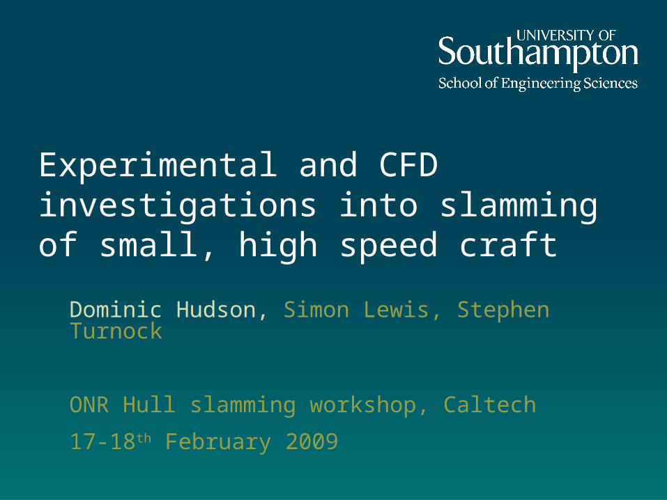
Background• Work in support of
Design of High Performance Craft from a Human Factors Perspective
• This involves:
• Model and full scale testing• Measurements of muscle fatigue and
heart rate on passengers on board
• Prediction of motions of high speed craft
• Suspension seat design
Heart rate and Oxygen consumption
0%
10%
20%
30%
40%
50%
60%
70%
1 11 21 31 41 51 61 71 81 91 101 111
Time (minutes)
Pe
rce
nta
ge
ma
xim
al
He
art
ra
te
0%
5%
10%
15%
20%
25%
30%
35%
40%
45%
Pe
rce
nta
ge
VO 2m
ax
heart rate VO2
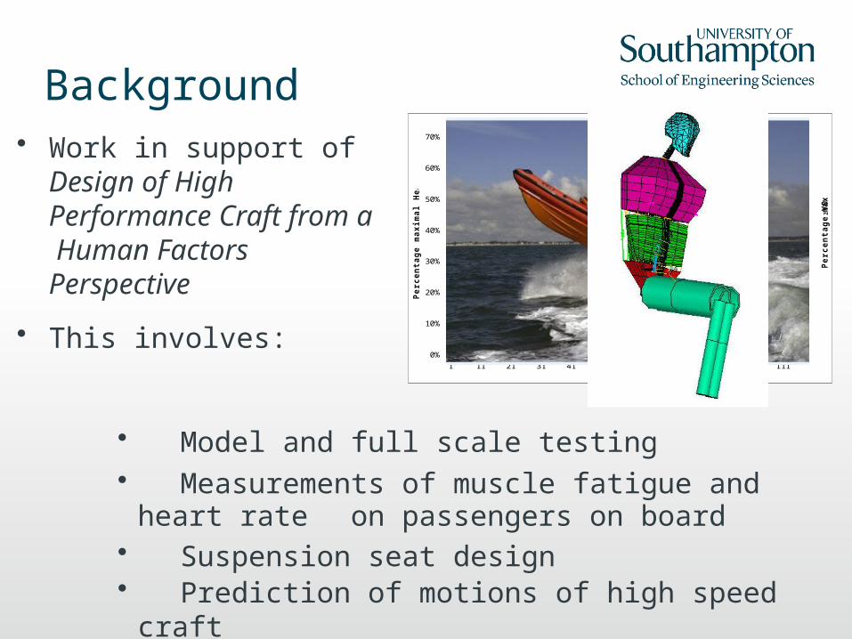
Outline
• Methods for prediction of planing craft motions
• Computational Fluid Dynamics (CFD) to predict vertical motion
• Improvements to CFD - boundary layer flow
• Wedge impact experiment
• Conclusions and future work
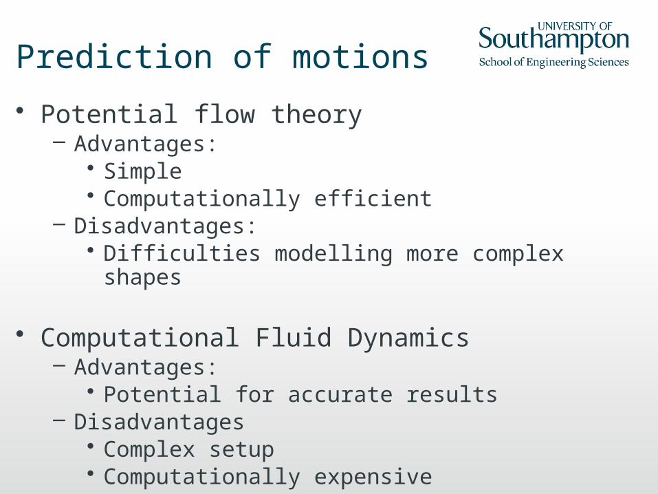
Prediction of motions
• Potential flow theory– Advantages:
• Simple• Computationally efficient
– Disadvantages:• Difficulties modelling more complex shapes
• Computational Fluid Dynamics– Advantages:
• Potential for accurate results– Disadvantages
• Complex setup • Computationally expensive
2D CFD - wedge impact• Computational fluid dynamics method using
– RANS equations (ANSYS CFX 11)
• Transient simulation
• Equations of motion solved at each timestep
• Initial investigations used published experimental data for validation
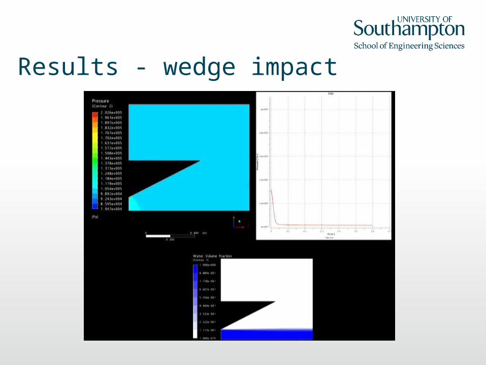
Results - wedge impact
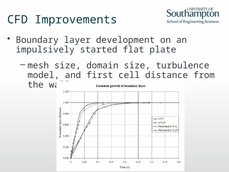
CFD Improvements
• Boundary layer development on an impulsively started flat plate
– mesh size, domain size, turbulence model, and first cell distance from the wall
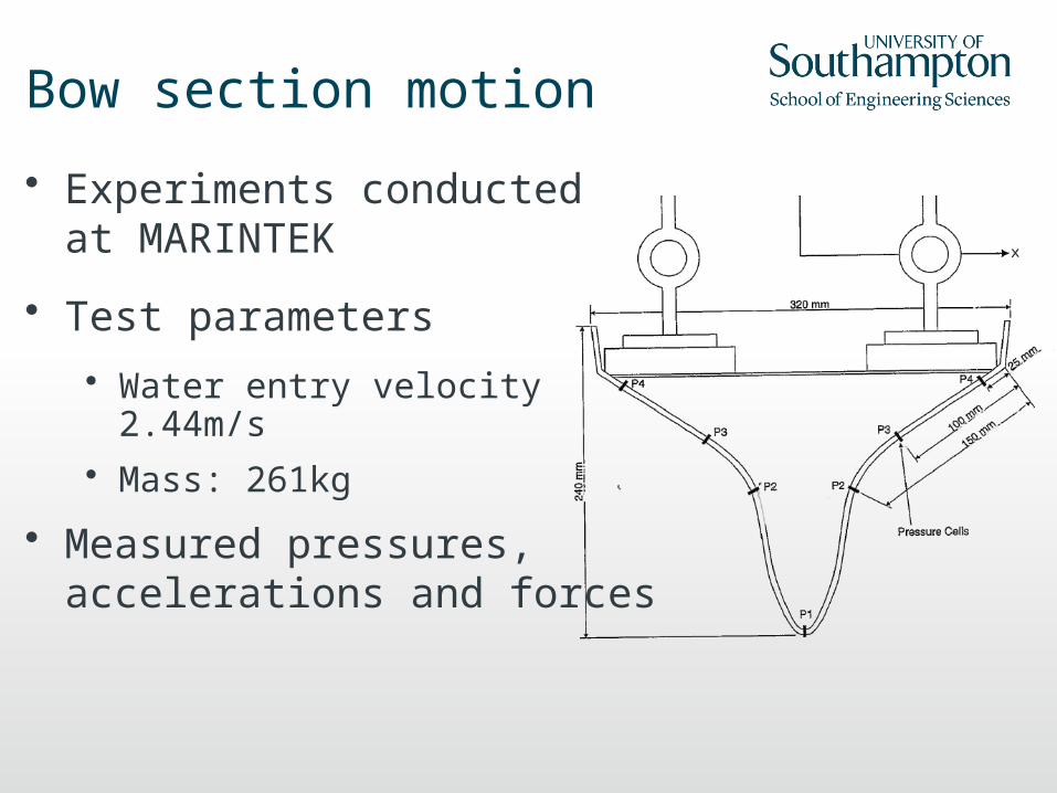
Bow section motion
• Experiments conducted at MARINTEK
• Test parameters
• Water entry velocity 2.44m/s• Mass: 261kg
• Measured pressures, accelerations and forces
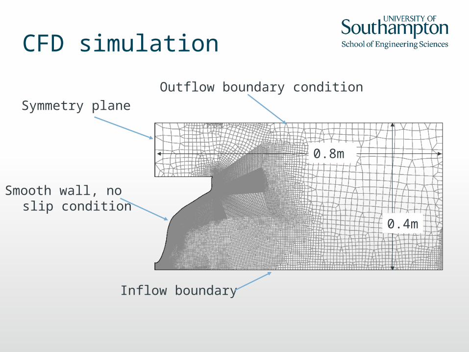
CFD simulation
Inflow boundary
Symmetry planeOutflow boundary condition
Smooth wall, no slip condition
0.8m
0.4m
CFD Parameters
• Using Ansys CFX v11.0
• Finest mesh: 30000 cells
• First element situated 2*10-5m from the wall
• Turbulence model used is k-omega
• Y+ value at the wall is 0.6
• Inhomogeneous multiphase model
• Motions are calculated through user defined functions in Matlab for each timestep
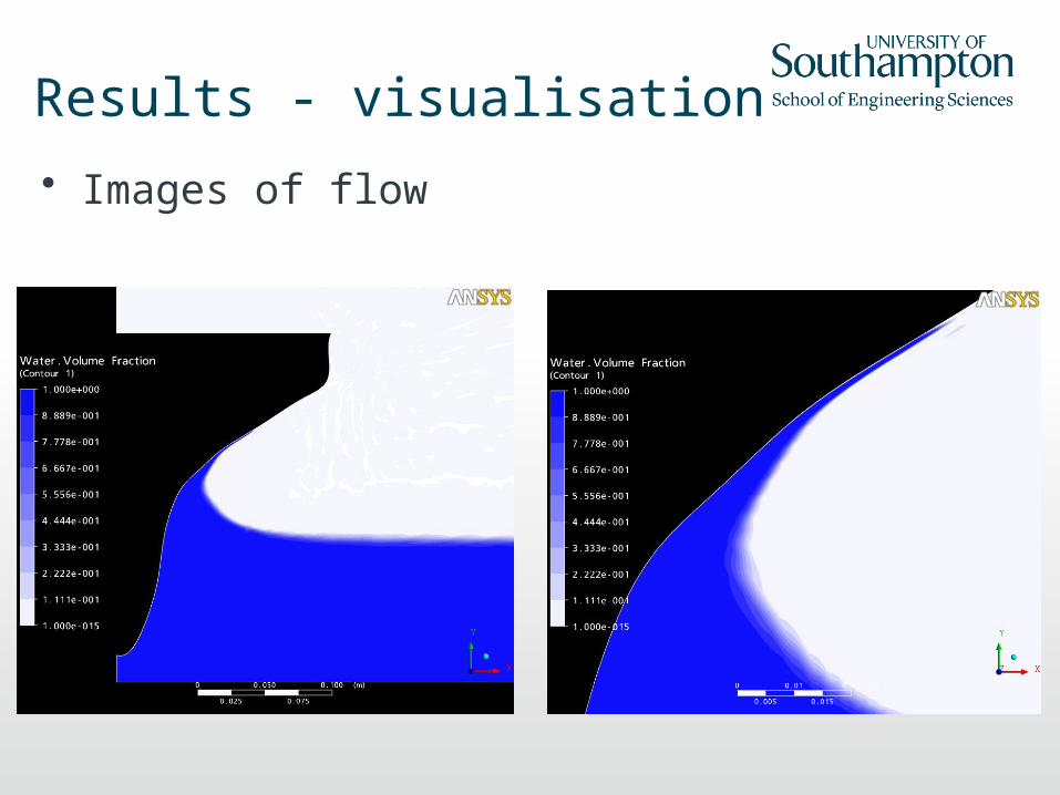
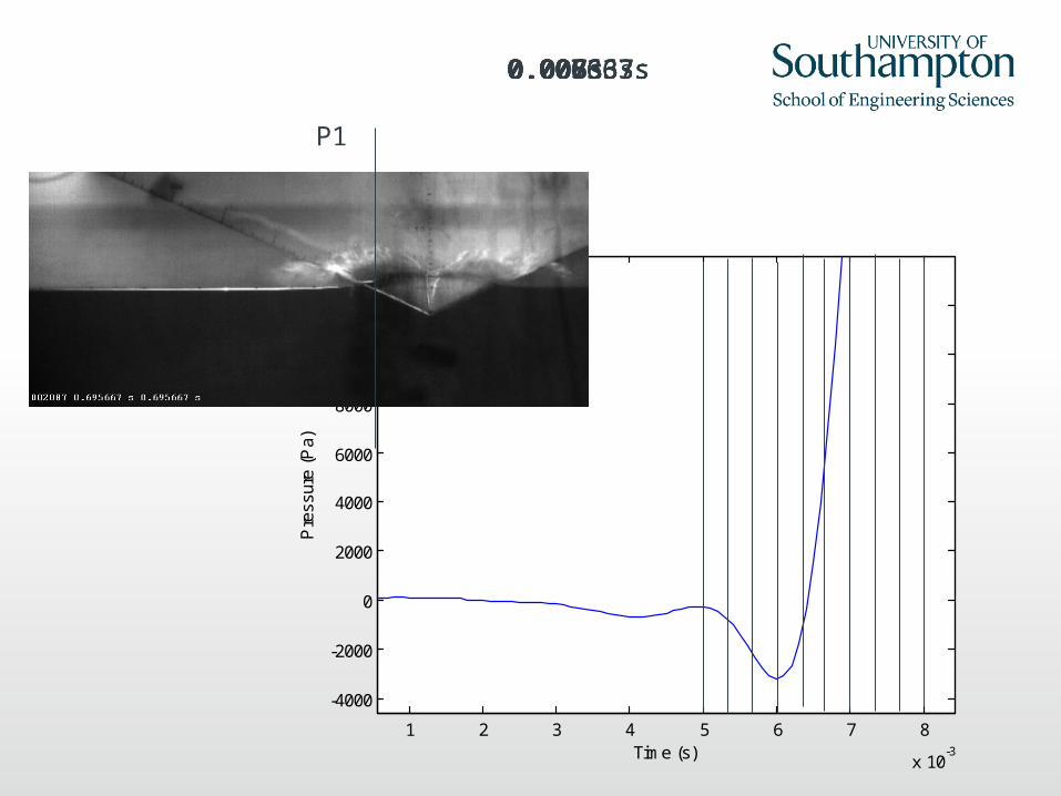
Results - visualisation
• Images of flow
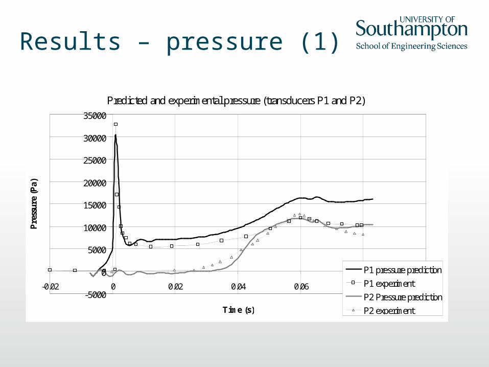
Results – pressure (1)
Predicted and experimental pressure (transducers P1 and P2)
-5000
0
5000
10000
15000
20000
25000
30000
35000
-0.02 0 0.02 0.04 0.06 0.08 0.1
Time (s)
Pre
ssur
e (P
a)
P1 pressure prediction
P1 experiment
P2 Pressure prediction
P2 experiment
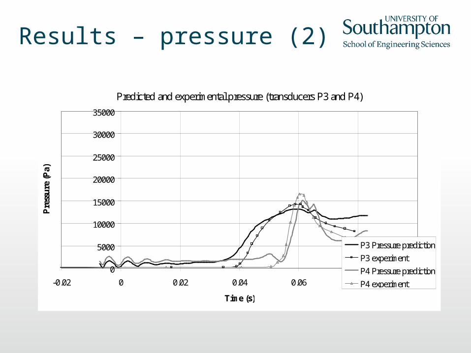
Results – pressure (2)
Predicted and experimental pressure (transducers P3 and P4)
0
5000
10000
15000
20000
25000
30000
35000
-0.02 0 0.02 0.04 0.06 0.08 0.1
Time (s)
Pre
ssu
re (
Pa)
P3 Pressure prediction
P3 experiment
P4 Pressure prediction
P4 experiment

Experimental testing
• Rig designed to investigate free-falling wedge
– Provide detailed validation data – Include uncertainty analysis– Improve understanding
• Synchronised high speed video, pressure and acceleration data
• Pressure, acceleration sampled at 10kHz
• Mass and drop height varied
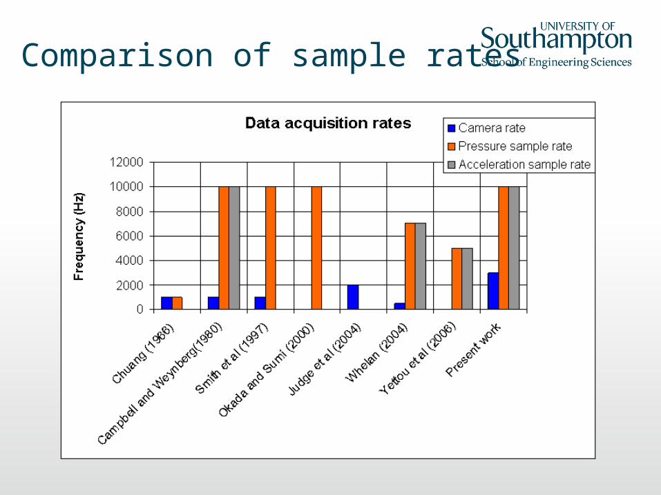
Comparison of sample rates
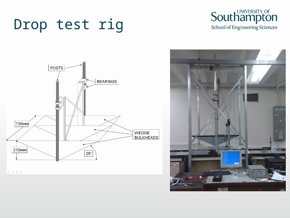
Drop test rig
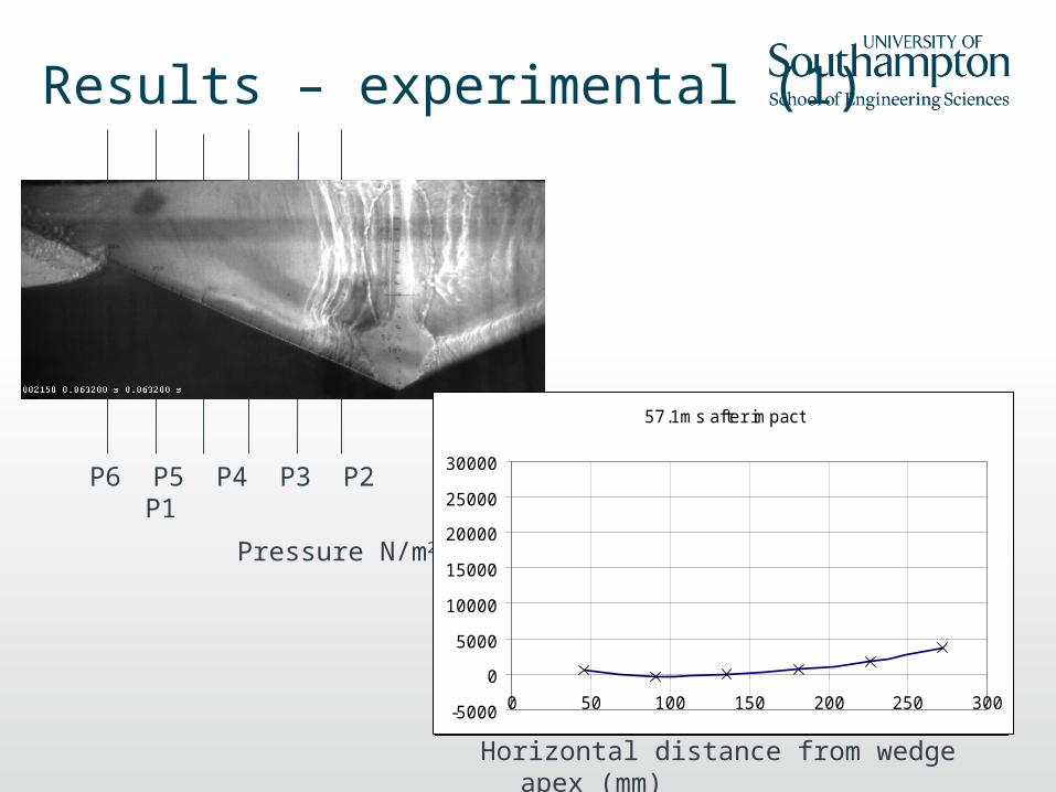
Results – experimental (1)
Pressure N/m2
8.8ms after impact
-5000
0
5000
10000
15000
20000
25000
30000
0 50 100 150 200 250 300
15ms after impact
-5000
0
5000
10000
15000
20000
25000
30000
0 50 100 150 200 250 300
21.6ms after impact
-5000
0
5000
10000
15000
20000
25000
30000
0 50 100 150 200 250 300
30.9ms after impact
-5000
0
5000
10000
15000
20000
25000
30000
0 50 100 150 200 250 300
42.8ms after impact
-5000
0
5000
10000
15000
20000
25000
30000
0 50 100 150 200 250 300
57.1ms after impact
-5000
0
5000
10000
15000
20000
25000
30000
0 50 100 150 200 250 300
Horizontal distance from wedge apex (mm)
P6 P5 P4 P3 P2 P1
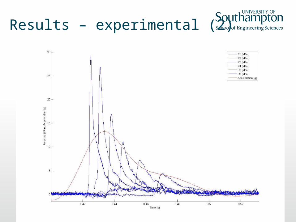
Results – experimental (2)
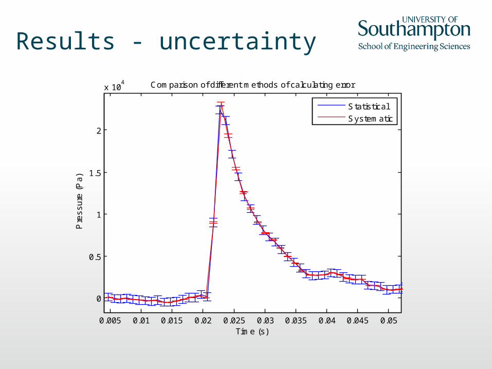
Results - uncertainty
0.005 0.01 0.015 0.02 0.025 0.03 0.035 0.04 0.045 0.05
0
0.5
1
1.5
2
x 104
Time (s)
Pre
ss
ure
(P
a)
Comparison of different methods of calculating error
Statistical
Systematic
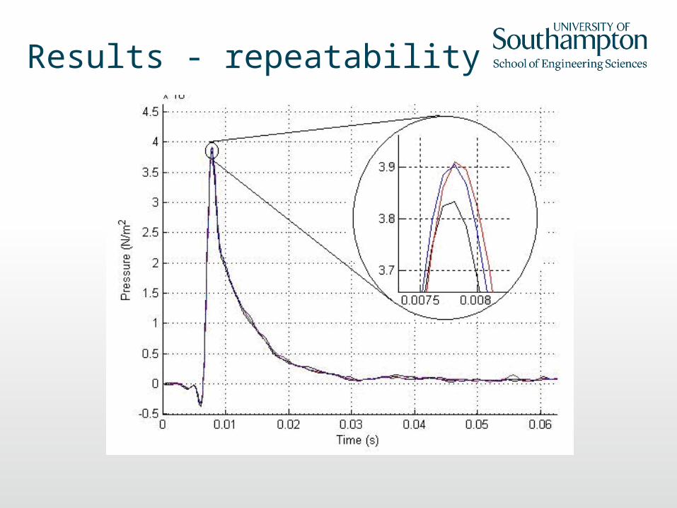
Results - repeatability
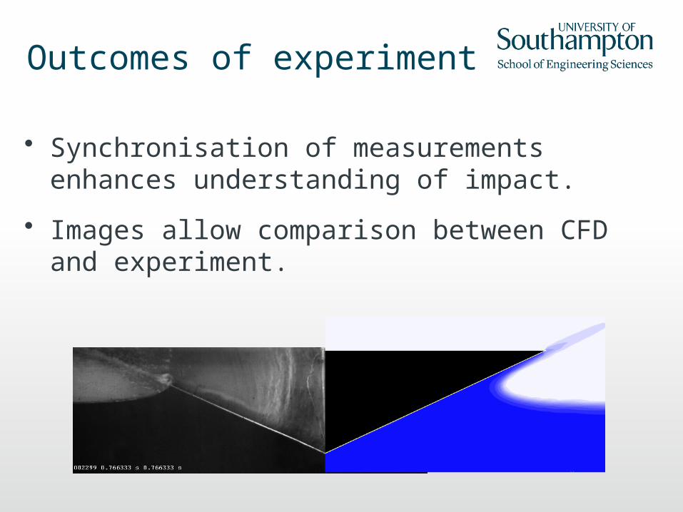
Outcomes of experiment
• Synchronisation of measurements enhances understanding of impact.
• Images allow comparison between CFD and experiment.
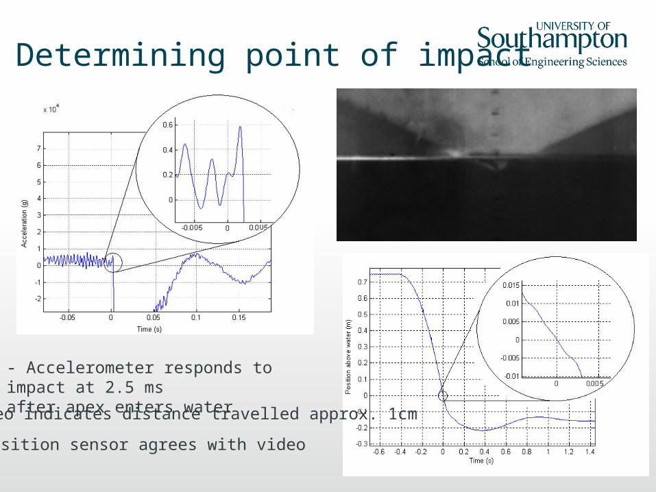
Determining point of impact
- Accelerometer responds to impact at 2.5 msafter apex enters water- Video indicates distance travelled approx. 1cm
- Position sensor agrees with video
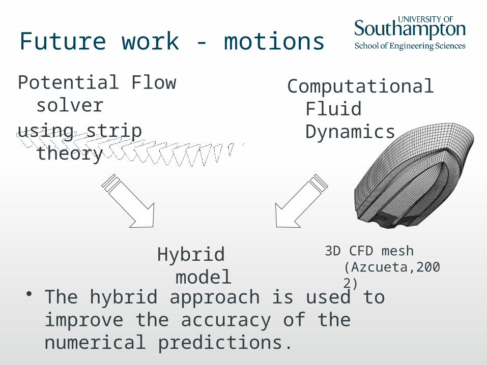
Future work - motions
Potential Flow solver
using strip theory
Computational Fluid Dynamics
Hybrid model
3D CFD mesh (Azcueta,2002)
• The hybrid approach is used to improve the accuracy of the numerical predictions.
Future work - general
• Use ‘flexible’ wedge – measure structural responses
– Strain gauges, thermo-elastic stress analysis?, digital image correlation?
• Effect of hull features on flow – deadrise, spray rails, hull shape, RIB collars
• Inclined wedge entry – heeled conditions
• Use high-speed video to investigate spray characteristics
• Modify rig for forced wedge entry/exit
Conclusions• Experimental study provides good data for
validation of wedge impact.
• Improvements to CFD predictions for highly non-linear flows such as water impact.
• Hybrid approach can be used to improve the accuracy of high speed craft motions prediction.
1 2 3 4 5 6 7 8
x 10-3
-4000
-2000
0
2000
4000
6000
8000
10000
12000
Time (s)
Pre
ssur
e (P
a)
0.005s
P1
0.005667s0.00533s0.006s0.006333s0.006667s0.007s0.007333s0.007667s0.008s

Questions
?
Thank you for your attention.