EFFECTS OF PISTON SPEED, COMPRESSION RATIO, AND CYLINDER ...

International Journal of Scientific Research and Management Studies (IJSRMS)
ISSN: 23493771 Volume 1 Issue 12, pg: 382-395
http://www.ijsrms.com ©IJSRMS pg. 382
EXPERIMENTAL ANALYSIS OF VAPOUR COMPRESSION
REFRIGERATION SYSTEM WITH LIQUID LINE SUCTION
LINE HEAT EXCHANGER BY USING R134A AND R404A
G. MaruthiPrasad Yadav1, P. RajendraPrasad2, G.Veeresh3 1&2Associate Professor, Mechanical Engineering Dept, St Johns College of Engg&
Technology, Yemmiganur-518360, Kurnool (Dist), AP, India 3PG Student, Mechanical Engineering Dept, St Johns College of Engg& Technology,
Yemmiganur-518360, Kurnool (Dist), AP, India
ABSTRACT
Because of simplicity and low cost, capillary tubes are used as the expansion device in most small refrigeration
and air conditioning systems. Another advantage is that capillary tubes allow high and low side pressures to
equalize during the off-cycle, thereby reducing the starting torque required by the compressor. In this
application the liquid line is usually placed in contact with the suction line, forming a counter flow heat
exchanger. The liquid line is welded to the suction line in the lateral configuration. The temperature of the
vapour refrigerant coming out from the evaporator is less than the temperature of the liquid coming out from
the condenser. Before the expansion process, heat is transferred from the liquid line to the suction line. As a
consequence this in turn reduces the refrigerant quality at the inlet of the evaporator and therefore increases the
refrigerating capacity. The suction line exit temperature also increases, eliminating suction line sweating and
preventing slugging of the compressor. The main objective of this project is to evaluate the performance of
refrigerator with liquid line suction line heat exchanger for different lengths of heat exchanger by using R134a
and R404a as refrigerants and compare with different lengths of liquid line- suction line heat exchanger.
KEYWORDS: Refrigeration, COP, heat exchanger, refrigerant.
I. INTRODUCTION
Vapour compression Refrigeration system is an improved type of air refrigeration system. The ability
of certain liquids to absorb enormous quantities of heat as they vaporize is the basis of this system.
Compared to melting solids (say ice) to obtain refrigeration effect, vaporizing liquid refrigerant has
more advantages. To mention a few, the refrigerating effect can be started or stopped at will, the rate
of cooling can be predetermined, the vaporizing temperatures can be governed by controlling the
pressure at which the liquid vaporizes. Moreover, the vapor can be readily collected and condensed
back into liquid state so that same liquid can be re-circulated over and over again to obtain
refrigeration effect. Thus the vapor compression system employs a liquid refrigerant which evaporates
and condenses readily. The System is a closed one since the refrigerant never leaves the system.
The coefficient of performance of a refrigeration system is the ratio of refrigerating effect to the
compression work; therefore the coefficient of performance can be increased by increasing the
refrigerating effect or by decreasing the compression work.
The Vapor compression refrigeration system is now-a-days used for all purpose refrigeration. It is
generally used for all industrial purposes from a small domestic refrigerator to a big air-conditioning
plant.
Energy analysis of Refrigeration
International Journal of Scientific Research and Management Studies (IJSRMS)
ISSN: 23493771 Volume 1 Issue 12, pg: 382-395
http://www.ijsrms.com ©IJSRMS pg. 383
Consider a boundary enclosing a space in which a refrigerator is placed. It is clear that some heat q2 is
given out at temperature higher than the surroundings. It is also clear that the foodstuff placed inside
the refrigerator is cooled by giving out their heat to the refrigerator which in turn, so to say, absorbs
heat q1, of course at lower temperature than the surroundings. Every refrigerator is supplied with
energy wither in the form of heat or electricity, that is, some work (w) is provided to it. The
refrigerating device, thus is absorbing heat at lower temperature and giving out at higher temperature;
this is usually not possible in our day to day life, since heat cannot flow from lower to higher
temperature, but in case of a refrigerator this is achieved at the cost of energy supplied to it. For the
boundary total heat given out (q2) is equal to the total energy input in the form of heat absorbed (q1)
and the work absorbed (w) Balancing them.
For a refrigerator device, we are interested in how much heat is extracted from food stuff and how
little electrical energy we spend, minimizing our power bill. The ratio of heat absorbed to the work
input in the form of electric energy (w) is called coefficient of performance (COP). The ratio should
be as high as possible.
COP = q1/w = q1/q2-q1
Theoretical COP is ratio of theoretical refrigerating effect (N), found from pressure heat content chart
or temperature-entropy chart to the theoretical compressor work (W) or isentropic compressor work,
found from the chart. Actual COP is the ratio of actual cooling effect, to the actual energy supplied to
the compressor known from watt-hour reading.
II. SELECTION OF CONDENSER FOR A VCR SYSTEM
2.1 Condenser
Condenser is that component which is placed next to compressor in a vapor compression refrigeration
system. It is a heat exchanger that affects heat transfer between refrigerant gas, vapor or super
saturated vapor coming from compressor and cooling medium such as air or water. It removes heat
absorbed by refrigerant in the evaporator and the heat of compression added in the compressor and
condenses it back to liquid. The condenser abstracts the latent heat from high pressure refrigerant at
the same pressure and constant temperature. For this purpose the condenser employs a cooling
medium such as air or water.
2.1.1 Gross Heat Rejection
The refrigeration effect and the heat rejection rate of the system will vary depending on the actual
balance to evaporator, compressor and condenser. Once the compressor and evaporator are selected to
perform the required cooling it is essential that the condenser be selected on the basis of the capability
of these components. Thus, the selection is made not on the heat gain, but rather on the actual load on
the condenser. It is also important to anticipate overload conditions on the evaporator and compressor
that may occur at start-up, pull down, or unusual loading so that these may be considered in the
condenser selection.
Great variation in compression heat occurs with variation in the ratio of the suction pressure and the
discharge pressure. Large compression ratio needs more compression work. However, the heat loss
from the compressor body, discharge gas piping are neglected in this energy as these are very small.
Since the heat transfer through the condenser is by conduction, condenser capacity is a function of the
fundamental heat transfer equitation.
Qc = U.A. (LMTD)
Where
Qc = Condenser capacity in KJ/Sec. (Ref. Effect Heat of Comp. +
Motor Wdg. Heat)
U = Overall heat transfer coefficient KJ/h-m20K
A = Effective surface area in m2
LMTD = the log mean temperature difference between the condensing refrigerant and
condensing medium 0K
International Journal of Scientific Research and Management Studies (IJSRMS)
ISSN: 23493771 Volume 1 Issue 12, pg: 382-395
http://www.ijsrms.com ©IJSRMS pg. 384
From the above equation it is evident that for any fixed value of ‘U’ the capacity of condenser is
directly proportional to the surface area of the condenser and to the temperature difference between
the condensing refrigerant and condensing medium.
2.1.2 Ambient Temperature
While selecting suitable ambient temperature in condenser sizing, it is kept in mind that the value of
ambient temperature in working out the TD is not taken at a very conservative value. The realistic one
is always found to be more accurate and economical in final selection of a condenser. In the normal
course while sizing condenser the ambient air temperature of 38°C has been found satisfactory.
2.1.3 Condensing temperature
The condensing temperature depends on the type of refrigerant, the type of condenser, and the
compressor capability. The type of refrigerant influences the condensing pressure, the superheated gas
temperature, and mass flow required. The condensing pressure and the gas temperature in turn affect
the power consumption and the cooling capacity of the system. It is, therefore, necessary to select a
condensing temperature based on the recommendation of compressor manufactures more on realistic
basis than on conservative basis in which case condenser size will work out to be too large.
2.1.4 Temperature Difference (TD)
Air cooled condensers are normally rated on the basis of initial temperature difference (TD) which is
the difference between the saturated temperature of the condensing refrigerant and the entering dry
bulb air temperature. The capacity of the condenser is proportional to the temperature difference so
that an increase in temperature difference increases the capacity of the condenser. Therefore, a higher
temperature difference means that a physically smaller condenser may be adequate for necessary heat
dissipation.
The proof of a good condenser selection comes only during the operating season when satisfactory
operation without problems at various conditions.
It has been the practice to select a TD of 12°C in sizing an air-cooled condenser. Still other establishes
a nominal condensing temperature and subtracts the highest recorded ambient temperature to
determine the temperature difference providing enough margin of safety (conservative method). In
such cases 55°C condensing temperature is considered satisfactory design temperature.
A recommendation for improved application is to determine a reasonable ambient temperature (10%
percent level), determine the maximum condensing temperature for the compressor’s capacity, and
utilize 6% of the difference as the design temperature difference:
TD = 0.6(CT max - ta)
Whereas CT max = maximum condensing temperature for compressor selected, °C.
ta=ambient air temperature at10% design level °C DB
III. HEAT EXCHANGER
Heat exchangers are devices used to transfer heat energy from one fluid to another. Typical heat
exchangers experienced by us in our daily lives include condensers and evaporators used in air
conditioning units and refrigerators. Boilers and condensers in thermal power plants are examples of
large industrial heat exchangers. There are heat exchangers in our automobiles in the form of radiators
and oil coolers. Heat exchangers are also abundant in chemical and process industries.
There is a wide variety of heat exchangers for diverse kinds of uses, hence the construction also
would differ widely. However, in spite of the variety, most heat exchangers can be classified into
some common types based on some fundamental design concepts. We will consider only the more
common types here for discussing some analysis and design methodologies.
Basic Heat Exchanger Flow Arrangements
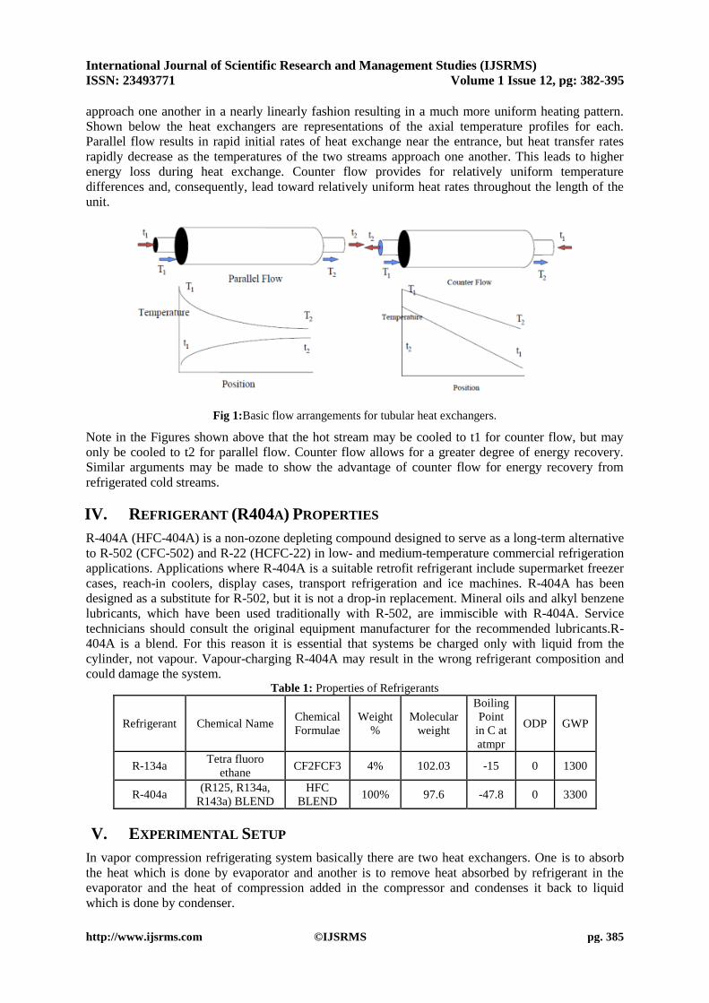
Two Basic flow arrangements are as shown in Figure 1. Parallel and counter flow provides alternative
arrangements for certain specialized applications. In parallel flow both the hot and cold streams enter
the heat exchanger at the same end and travel to the opposite end in parallel streams. Energy is
transferred along the length from the hot to the cold fluid so the outlet temperatures asymptotically
approach each other. In a counter flow arrangement, the two streams enter at opposite ends of the heat
exchanger and flow in parallel but opposite directions. Temperatures within the two streams tend to
International Journal of Scientific Research and Management Studies (IJSRMS)
ISSN: 23493771 Volume 1 Issue 12, pg: 382-395
http://www.ijsrms.com ©IJSRMS pg. 385
approach one another in a nearly linearly fashion resulting in a much more uniform heating pattern.
Shown below the heat exchangers are representations of the axial temperature profiles for each.
Parallel flow results in rapid initial rates of heat exchange near the entrance, but heat transfer rates
rapidly decrease as the temperatures of the two streams approach one another. This leads to higher
energy loss during heat exchange. Counter flow provides for relatively uniform temperature
differences and, consequently, lead toward relatively uniform heat rates throughout the length of the
unit.
Fig 1:Basic flow arrangements for tubular heat exchangers.
Note in the Figures shown above that the hot stream may be cooled to t1 for counter flow, but may
only be cooled to t2 for parallel flow. Counter flow allows for a greater degree of energy recovery.
Similar arguments may be made to show the advantage of counter flow for energy recovery from
refrigerated cold streams.
IV. REFRIGERANT (R404A) PROPERTIES
R-404A (HFC-404A) is a non-ozone depleting compound designed to serve as a long-term alternative
to R-502 (CFC-502) and R-22 (HCFC-22) in low- and medium-temperature commercial refrigeration
applications. Applications where R-404A is a suitable retrofit refrigerant include supermarket freezer
cases, reach-in coolers, display cases, transport refrigeration and ice machines. R-404A has been
designed as a substitute for R-502, but it is not a drop-in replacement. Mineral oils and alkyl benzene
lubricants, which have been used traditionally with R-502, are immiscible with R-404A. Service
technicians should consult the original equipment manufacturer for the recommended lubricants.R-
404A is a blend. For this reason it is essential that systems be charged only with liquid from the
cylinder, not vapour. Vapour-charging R-404A may result in the wrong refrigerant composition and
could damage the system. Table 1: Properties of Refrigerants
Refrigerant Chemical Name Chemical
Formulae
Weight
%
Molecular
weight
Boiling
Point
in C at
atmpr
ODP GWP
R-134a Tetra fluoro
ethane CF2FCF3 4% 102.03 -15 0 1300
R-404a (R125, R134a,
R143a) BLEND
HFC
BLEND 100% 97.6 -47.8 0 3300
V. EXPERIMENTAL SETUP
In vapor compression refrigerating system basically there are two heat exchangers. One is to absorb
the heat which is done by evaporator and another is to remove heat absorbed by refrigerant in the
evaporator and the heat of compression added in the compressor and condenses it back to liquid
which is done by condenser.

International Journal of Scientific Research and Management Studies (IJSRMS)
ISSN: 23493771 Volume 1 Issue 12, pg: 382-395
http://www.ijsrms.com ©IJSRMS pg. 386
This work focuses on heat rejection in the condenser this is only possible either by providing a fan or
by extending the surfaces. The extended surfaces are called fins. The rate of heat rejection in the
condenser depends upon the number of fins attached to the condenser.
This work investigated the performance of condenser using condenser in the present domestic
refrigerator galvanized iron steel material fins are used. In this project mild steel material fins are
replaced and galvanized iron steel is used for the condensers.
The performance of the condenser will also help to increase COP of the system as the sub cooling
region .incurred at the exit of the condenser. The performance of the condenser is also investigated by
existing and modification condenser. In general domestic refrigerators have no fans at the condenser
and hence extended surfaces like fins play a very vital role in the rejection of heat.
In order to know the performance characteristics of the vapor compression refrigerating system the
temperature and pressure gauges are installed at each entry and exit of the component. Experiments
are conducted on condenser having fins.
Different types of tools are also used like snips to cut the plated fins to required sizes, tube cutter to
cut the tubes and tube bender to bend the copper tube to the required angle. Finally the domestic
refrigerator is fabricated as for the requirement of the project. All the values of pressures and
temperatures are tabulated.
The figure 4 shows the experimental setup of the refrigerator. In order to know the performance
characteristics of the vapor compression refrigeration system the temperature and pressure gauges are
installed at each entry and exit of the components. Experiments are conducted on condenser with
coil spacing of the condenser on a refrigerator of capacity 215liters.All the values of pressures and
temperatures are tabulated.
Domestic refrigerator selected for the project has the following specifications Refrigerant used: R-134a
Capacity of The Refrigerator: 160 liters
Compressor capacity: 0.16 H.P.
Condenser Sizes Length - 8.5 m
Diameter - 6.4 mm
Evaporator Length - 7.62 m
Diameter - 6.4 mm
Capillary tube Length - 2.428 m
Diameter - 0.8 mm
Among many possible variations of the basic refrigeration cycle, the cycle with the liquid-
line/suction-line heat exchanger (LLSL-HX) is probably used most often. As a result of employing
this intra cycle heat exchange, the high pressure refrigerant is sub cooled at the expense of
superheating the vapour entering the compressor. Schematics of hardware arrangement for the basic
cycle and cycle with LLSL-HX are shown in figure 3; the realized cycles are outlined on the pressure-
enthalpy diagram shown in figure 2.
The use of liquid line/suction line heat exchangers is widespread in commercial refrigeration. The
heat exchangers are often employed as a means for protecting system components, by helping to
ensure single-phase liquid to the expansion device and single phase vapour to the compressor. in
residential refrigerators, Capillary tube /suction-line heat exchanger is used to heat the suction line
above the dew-point temperature of ambient air, thus preventing condensation of the water vapour on
the outside of the water vapour on the outside of the suction line.
Employing an intra-cycle heat exchanger alters refrigerant thermodynamic states in the cycle, which
may have significant (positive or negative) performance implications. For any fluid and system, an
LLSL-HX increases refrigerant temperature at the compressor inlet and outlet, which is shortcoming.
The coefficient of performance (COP) and volumetric capacity may increase for some fluid-
application combinations, while for others they may decrease.

International Journal of Scientific Research and Management Studies (IJSRMS)
ISSN: 23493771 Volume 1 Issue 12, pg: 382-395
http://www.ijsrms.com ©IJSRMS pg. 387
Figure 2 key refrigerant state points in the basic cycle and LLSL-HX cycle
Figure 3hardware arrangements for a)The basic cycle b)cycle with the liquid-line/suction-line heat exchanger
Fig 4 New System with heat exchanger length of 30cms
VI. EXPERIMENTAL PROCEDURE
The following procedure is adopted for experimental setup of the vapor compression refrigeration
system

International Journal of Scientific Research and Management Studies (IJSRMS)
ISSN: 23493771 Volume 1 Issue 12, pg: 382-395
http://www.ijsrms.com ©IJSRMS pg. 388
1. The domestic refrigerator is selected, working on vapor compression refrigeration system.
2. Pressure and temperature gauges are installed at each entry and exit of the components.
3. Flushing of the system is done by pressurized nitrogen gas.
4. R 134a refrigerant is charged in to the vapor compression refrigeration system by the
following process:
The systematic line diagram for charging is shown in the fig 5. it is necessary to remove the air from
the refrigeration unit before charging. First the valve V2 is closed and pressure gauge P2, vacuum
gauge V are fitted as shown in the fig. the valve V5 is also closed and valves V1, V4, V6 and V3 are
opened and the motor is started thus the air from the condenser receiver and evaporator is sucked
through the valve V1 and it is discharged in to atmosphere through the valve V6 after compressing it in
the compressor the vacuum gauge V indicates sufficiently low vacuum when most of the air is
removed in the system. The vacuum reading should be at least 74 to 75 cm of Hg. If the vacuum is
retained per above an hour it may be concluded that the system is free from the air. After removing
the air the compressor is stopped and valves V1 and V6 are closed, the valves V5, V2 and V7 of the
refrigerant cylinder are opened and then the compressor is started whenever the sufficient quantity of
refrigerant is taken in to the system which will be noted in the pressure gauges. The compressor is
stopped. The valves V7 and V5 are closed and valve V1 is opened the refrigerant cylinder is
disconnected from the system the pressure gauge is used to note the pressure during the charging the
system. Same procedure is followed for R 404a.
Fig.5 charging of refrigeration system
5. Leakage tests are done by using soap solution, In order to further test the condenser and
evaporator pressure and check purging daily for 12 hours and found that there is no leakages
which required the absolutely the present investigation to carry out further experiment.
6. Switch on the refrigerator and observation is required for 1 hour and take the pressure and
temperature readings at each section.
7. The performance of the existing system is investigated, with the help of temperature and
pressure gauge readings.
8. The refrigerant is discharged out and condenser is located at the inlet of the capillary tube.
9. Temperature and pressure gauge readings are taken and the performance is investigated.
10. The readings are tabulated for the length of heat exchanger of 10cm, 20cm&30cm.
The following tests are conducted and calculations are shown below.
VII. PERFORMANCE CALCULATIONS
The temperature, pressure and enthalpy at state points for the system using R134a by adopting heat
exchanger with different lengths is shown in following table.

International Journal of Scientific Research and Management Studies (IJSRMS)
ISSN: 23493771 Volume 1 Issue 12, pg: 382-395
http://www.ijsrms.com ©IJSRMS pg. 389
Table 2: Temperature, Pressure and enthalpy readings at state points using R134a with and without heat
exchanger
Parameter Heat Exchanger length(R134a)
Exist 10 20 30
Compressor Discharge Temperature T2(°C) 59.2 60 60 60
Condensing Temperature T3(°C) 44 44 44 43
Evaporator Temperature T4(°C) -15 -15 -15 -15
Compressor suction pressure P1(bar) 1.03 1.03 1.03 1.02
Compressor discharge pressure P2(bar) 12.75 12.75 12.75 12.75
Condenser pressure P3 (bar) 12.75 12.75 12.75 12.75
Evaporator pressure P4(bar) 1.03 1.03 1.03 1.02
Enthalpy,h1 (kJ/kg) 395 395 396 396
Enthalpy,h2 ( kJ/kg) 436 436 436 436
Enthalpy,h3 (kJ/kg) 262 262 262 260
Enthalpy,h4 (kJ/kg) 262 262 262 260
Existing system(r134a)
Calculation of Performance Parameters
1. Net Refrigerating Effect (NRE) = h1-h4 = 395-262 = 131 kJ/kg
2. Mass flow rate to obtain one TR, kg/min.
mr= 210/NRE = 210/142 = 1.603 kg/min.
3. Work of Compression = h2-h1 = 436-395 = 41 kJ/kg
4. Heat Equivalent of work of compression per TR
mr x (h2-h1) = 1.603 x 41 = 65.723 kJ/min
5. Theoretical power of compressor = 65.723/60 = 1.0953 kW
6. Coefficient of Performance (COP) = h1-h4 / h2-h1 = 131/41 = 3.24
7. Heat to be rejected in condenser = h2-h3 = 436-262 = 174 kJ/kg
8. Heat Rejection per TR = (210/NRE) x (h2-h3)= 1.603x 174 = 2782.92 kJ/min
9. Heat Rejection Ratio = 272.65/210 = 1.298
10. Compression Pressure Ratio = 𝑫𝒊𝒔𝒉𝒄𝒂𝒓𝒈𝒆 𝑷𝒓𝒆𝒔𝒔𝒖𝒓𝒆
𝑺𝒖𝒄𝒕𝒊𝒐𝒏 𝑷𝒓𝒆𝒔𝒔𝒖𝒓𝒆 =
𝑷𝒅
𝑷𝒔 =12.72/1.03= 12.349
Repeating the experimentation using the same refrigerant R134a, by adopting heat exchanger with
different lengths, the performance parameters are calculated that are tabulated as follows. Table 3: Performance parameters using R134a with and without heat exchanger
Tim
PARAMETERS
Heat Exchanger length(R134a)
Exist 10 20 30
1 (COP) 3.24 3.24 3.35 3.4
2 Net refrigerating effect , kJ/kg 131 131 134 136
3 Work of Compression, kJ/kg 41 41 40 40
4 Compressor Power, kW 1.0953 1.09538 1.0446 1.0293
5 Mass flow rate to obtain one TR, kg/min 1.603 1.603 1.567 1.544
6 Heat Equivalent of work of compression per TR, kJ/kg 65.723 65.723 62.68 61.76
7 Heat rejected in condenser , kJ/kg 174 174 174 176
8 Heat Rejection per TR, kJ/min 2782.92 278.92 272.65 271.744
9 Heat Rejection Ratio 1.298 1.328 1.298 1.294
10 Compression Pressure Ratio 12.349 12.378 12.349 12.5
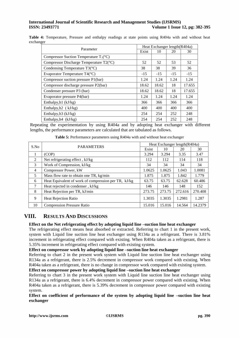
The temperature, pressure and enthalpy at state points for the system by using R404a by adopting heat
exchanger with different lengths is shown in following table.
International Journal of Scientific Research and Management Studies (IJSRMS)
ISSN: 23493771 Volume 1 Issue 12, pg: 382-395
http://www.ijsrms.com ©IJSRMS pg. 390
Table 4: Temperature, Pressure and enthalpy readings at state points using R404a with and without heat
exchanger
Parameter Heat Exchanger length(R404a)
Exist 10 20 30
Compressor Suction Temperature T1(°C)
Compressor Discharge Temperature T2(°C) 52 52 53 52
Condensing Temperature T3(°C) 38 38 39 36
Evaporator Temperature T4(°C) -15 -15 -15 -15
Compressor suction pressure P1(bar) 1.24 1.24 1.24 1.24
Compressor discharge pressure P2(bar) 18.62 18.62 18 17.655
Condenser pressure P3 (bar) 18.62 18.62 18 17.655
Evaporator pressure P4(bar) 1.24 1.24 1.24 1.24
Enthalpy,h1 (kJ/kg) 366 366 366 366
Enthalpy,h2 ( kJ/kg) 400 400 400 400
Enthalpy,h3 (kJ/kg) 254 254 252 248
Enthalpy,h4 (kJ/kg) 254 254 252 248
Repeating the experimentation by using R404a and by adopting heat exchanger with different
lengths, the performance parameters are calculated that are tabulated as follows.
Table 5: Performance parameters using R404a with and without heat exchanger
S.No PARAMETERS Heat Exchanger length(R404a)
Exist 10 20 30
1 (COP) 3.294 3.294 3.35 3.47
2 Net refrigerating effect , kJ/kg 112 112 114 118
3 Work of Compression, kJ/kg 34 34 34 34
4 Compressor Power, kW 1.0625 1.0625 1.043 1.0081
5 Mass flow rate to obtain one TR, kg/min 1.875 1.875 1.842 1.779
6 Heat Equivalent of work of compression per TR, kJ/kg 63.75 63.75 62.628 60.486
7 Heat rejected in condenser , kJ/kg 146 146 148 152
8 Heat Rejection per TR, kJ/min 273.75 273.75 272.616 270.408
9 Heat Rejection Ratio 1.3035 1.3035 1.2981 1.287
10 Compression Pressure Ratio 15.016 15.016 14.564 14.2379
VIII. RESULTS AND DISCUSSIONS
Effect on the Net refrigerating effect by adopting liquid line –suction line heat exchanger
The refrigerating effect means heat absorbed or extracted. Referring to chart 1 in the present work,
system with Liquid line suction line heat exchanger using R134a as a refrigerant. There is 3.81%
increment in refrigerating effect compared with existing. When R404a taken as a refrigerant, there is
5.35% increment in refrigerating effect compared with existing system.
Effect on compressor work by adopting liquid line –suction line heat exchanger
Referring to chart 2 in the present work system with Liquid line suction line heat exchanger using
R134a as a refrigerant, there is 2.5% decrement in compressor work compared with existing. When
R404a taken as a refrigerant, there is no change in compressor work compared with existing system.
Effect on compressor power by adopting liquid line –suction line heat exchanger
Referring to chart 3 in the present work system with Liquid line suction line heat exchanger using
R134a as a refrigerant, there is 6.4% decrement in compressor power compared with existing. When
R404a taken as a refrigerant, there is 5.39% decrement in compressor power compared with existing
system.
Effect on coefficient of performance of the system by adopting liquid line –suction line heat
exchanger

International Journal of Scientific Research and Management Studies (IJSRMS)
ISSN: 23493771 Volume 1 Issue 12, pg: 382-395
http://www.ijsrms.com ©IJSRMS pg. 391
Referring to chart 4 in the present work system with Liquid line suction line heat exchanger using
R134a as a refrigerant, there is 4.93% increment in co-efficient of performance of the system
compared with existing system. When R404a taken as a refrigerant, there is 5.34% increment in co-
efficient of performance of the system compared with existing system.
Effect on Heat rejection by adopting liquid line –suction line heat exchanger
Referring to chart 5 in the present work system with Liquid line suction line heat exchanger using
R134a as a refrigerant, there is 1.14% increment in heat rejection compared with existing system.
When R404a taken as a refrigerant, there is 4.10% increment in heat rejection compared with existing
system.
Chart 1: Effect of Heat exchanger length and
different refrigerants on Net Refrigerating effect
Chart 2: Effect of Heat exchanger length and
different refrigerants on compression work
Chart 3: Effect of Heat exchanger length and
different refrigerants on compressor power
Chart 4: Effect of Heat exchanger length and
different refrigerants on COP
020406080
100120140160
R1
34
a-Ex
ist
R1
34
a-1
0cm
R1
34
a-2
0cm
R1
34
a-3
0cm
R4
04
a-Ex
ist
R4
04
a-1
0cm
R4
04
a-2
0cm
R-4
04
a-3
0cm
Net refrigerating effect , kJ/kg
Netrefrigeratingeffect ,kJ/kg
0
10
20
30
40
50Work of Compression, kJ/kg
Work ofCompression, kJ/kg
0.960.98
11.021.041.061.08
1.11.12
Compressor Power, kW
CompressorPower,kW
3.13.15
3.23.25
3.33.35
3.43.45
3.5
CO
P
Heat Exchanger Length
(COP)

International Journal of Scientific Research and Management Studies (IJSRMS)
ISSN: 23493771 Volume 1 Issue 12, pg: 382-395
http://www.ijsrms.com ©IJSRMS pg. 392
Chart 5: Effect of Heat exchanger length and different refrigerants on Heat rejected
Already it is found from above results that providing heat exchanger gives better refrigeration effect
and now comparison has been made for the effect of heat exchanger length and refrigerants R134a
and R404a as follows.
Effect of heat exchanger length on refrigeration effect using refrigerants R134a and R404a is shown
graph 1. It is observed that as heat exchanger length increases the net refrigeration effect increases for
both the refrigerants under test. Also it is found that refrigeration effect is superior in case of R134a
than that of R404a. The maximum refrigeration effect obtained is 136Kj/Kg using R134a whereas the
same is 118Kj/kg for R404a.
Graph 1: Effect of Heat exchanger length on net Refrigeration effect using R134a and R404arefrigerants.
From the following graph 2 it is observed that as heat exchanger length increases COP of the system
also increases for both the refrigerants R134a and R404a. COP is superior for R404a than that of
R134a. The maximum COP using R404a is 2.05% higher than that of COP using R134a.
0
50
100
150
200Heat rejected in condenser ,
kJ/kg
Heatrejected incondenser ,kJ/kg
100
105
110
115
120
125
130
135
140
0 20 40
Net
Ref
riger
atio
n E
ffec
t
Heat Exchanger length
N.R.E-R134A
N.R.E-R404A
3.2
3.25
3.3
3.35
3.4
3.45
3.5
0 20 40
CO
P
Heat Exchanger length
COP-R134A
COP-R404A

International Journal of Scientific Research and Management Studies (IJSRMS)
ISSN: 23493771 Volume 1 Issue 12, pg: 382-395
http://www.ijsrms.com ©IJSRMS pg. 393
Graph 2: Effect of Heat exchanger length on COP using R134a and R404arefrigerants.
From the graph 3 it is found that increase of heat exchanger leads to increase of heat rejected for both
the refrigerants R134a and R404a. Heat rejection is higher for R134a than that of R404a. As the
length increases surface area increases, which in turn results in increase of heat rejection. Thou even
pressure drop occurs which opposes the heat rejection but its effect is small compare to the sensibility
of surface area increment. So ultimately slight improvement in found in heat rejection with increase of
heat exchanger length. The maximum heat rejected for R134a is 15.7% higher than that of R404a.
Graph 3: Effect of Heat exchanger length on heat rejected using R134a and R404arefrigerants.
From the graph 4 it is observed that increase of heat exchanger length decreases the power
consumption in both the cases of using R134a and R404a. Considering COP, refrigeration effect and
heat rejected the optimum length of heat exchanger is 30cm which saves power up to 2.1% for R134a
than that of using R404a.
Graph 4: Effect of Heat exchanger length on power consumption using R134a and R404arefrigerants.
IX. CONCLUSIONS
In the present work experimental investigation is carried out to investigate the performance of vapour
compression refrigeration system of a domestic refrigerator of 160 liters capacity, with R-134a and R-
404a as refrigerants by adopting different lengths of liquid line-suction line heat exchanger for
domestic refrigerator.
After conducting the experiments, the following conclusions are drawn.
Net refrigerating effect is increased for different lengths of liquid line-suction line heat
exchanger and at the length of heat exchanger of 30 cms is high for R134a is 136 and for
R404a is 118
Coefficient of performance is increased for different lengths of liquid line-suction line heat
exchanger and at the length of heat exchanger of 30 cms is high for R404a is 3.47 and for
R134a is 3.4
120
130
140
150
160
170
180
0 20 40
Hea
t R
ejec
ted
Heat Exchanger length
R134A
R404A
1
1.02
1.04
1.06
1.08
1.1
0 20 40
Po
wer
co
nsu
med
Heat Exchanger length
R134A
R404A

International Journal of Scientific Research and Management Studies (IJSRMS)
ISSN: 23493771 Volume 1 Issue 12, pg: 382-395
http://www.ijsrms.com ©IJSRMS pg. 394
Heat to be rejected in condenser is increased for different lengths of liquid line-suction line
heat exchanger and at the length of heat exchanger of 30 cms is high for R134a is 176 and for
R404a is 152
From the above discussions, it can be concluded that the performance of vapour compression
refrigeration system of domestic refrigerator can be increased by increasing the length of a
heat exchanger for different refrigerants. But there is a limitation to increase length due to the
fabrication difficulty.
REFERENCES
[1] Comakli K, Simsek F, Comakli O and Sahin B (2009), “Determination of Optimum Conditions R-22 and
R404a Refrigerant Mixtures in Heat Pumps Using Taguchi Method”, Applied Energy, Vol. 86, pp. 2451-2458.
[2] Havelsky V (2000), “Investigation of Refrigeration System with R12 Refrigerant Replacements”, Applied
Thermal Engineering, Vol. 20, pp. 133-140.
[3] Akhilesh Arora and Kaushik S C (2008), “Theoretical Analysis of a Vapour Compression Refrigeration
System with R502, R404A and R507A”, International Journal of Refrigeration, Vol. 31, pp. 998-1005.
[4] Bukola Olalekan Bolaji, Effects of Sub-Cooling on the Performance of R12 Alternatives in a Domestic
Refrigeration System, Thammasat International Journal Science and Technology, Vol. 15, No. 1, January-March
2010, pp. 12-19.
[5] V. Siva Reddy, N.L Panwar, S.C Kaushik(2012) “Exergy analysis of a vapour compression refrigeration
system with R134a,R143a,R152a,R404A,R407C,R410A,R502 and R507A” Int. Journal of .Clean Techn
Environ Policy;14, pp.47-53.
[6] Mahmood Mastani Joybari, Mohammad Sadegh Hatamipour, Amir Rahimi, Fatemeh Ghadiri
Modarres(2013) “Exergy analysis and optimization of R600a as a replacement of R134a in a domestic
refrigerator system. International Journal of refrigeration; Vol-36, pp.1233-1242.
[7] Eckels S.J. and Pate M.B. (1990) “An experimental comparison of evaporation and condensation heat
transfer coefficients for HFC-134a and CFC-12”, International Journal of Refrigeration, Vol 14, pp 70- 77
[8] Ding C.Z., Wen T.J. and Wen Q.T. (2007) “Condensation heat transfer of HFC 134a on horizontal low
thermal conductivity tubes”, International Communications in Heat and Mass Transfer, Vol.34, pp 917- 923
[9] R. Radermacher, K. Kim, “Domestic refrigerator: recent development”, International journal of refrigeration
vol 19 (1996) pp 61-69.
[10] R. Cabello, E. Torrella, J. Navarro-Esbr. “Experimental evaluation of a vapour compression plant
performance using R134a, R407C and R22 as working fluids”. Applied thermal Engineering (2004)
[11] Vaibhav Jain, S. S. Kachhwaha, R. S. Mishra. “Comparative performance study of vapour compression
refrigeration system with R22/R134a/R410A/R407C/M20”. International Journal of Energy and Environment,
Volume 2, Issue 2, 2011 pp.297-310
[12] JyotiSoni, R C Gupta, “Performance analysis of vapour compression refrigeration system with R404A,
R407C & R410A”. International Journal of mechanical engineering and robotics research, ISSN 2278 – 0149,
Vol. 2, No. 1, Jan 2013
[13] Performance enhancement of a household refrigerator by addition of latent heat storage International
Journal of Refrigeration, Volume 31, Issue 5, August 2008, Pages 892-901 Azzouz, K.; Leducq, D.; Gobin, D.
[14] Seshimo Y, Fujii M. An experimental study of the performance of plate fin and tube heat exchangers at low
Reynolds numbers. ASME/JSME Thermal Engineering Proceedings, ASME 1991; 4:449–54.
[15] Pannock, J; radermacher, R; Liu, Z and Yu, K (1994). “Evaluation of R-134a and R-152a as Working
Fluids in a Domestic Refrigerator/Freezer”. ASHRAE Transactions. Vol. 100 part I, pp 1344 – 1350.
[16] Bolaji, BO (2008). “Evaluation of Environmental Friendly Refrigerants”. A PhD Thesis in the Department
of Mechanical Engineering, Federal University f Technology, Akure, Nigeria.
[17] J. K. Dabas, A. K. Dodeja, Sudhir Kumar, K. S. Kasana, “Impact of Refrigerant Charge over the
Performance Characteristics of a Simple Vapour Compression Refrigeration System”, International Journal of
Advances in Engineering & Technology, Vol. 1, Issue 5, pp. 267-277, Nov 2011.
[18] Akintunde, MA (2007). “Effects of Coiled Capillary Tube Pitch on Vapour Compression Refrigeration
System Performance”. AU Journal. Vol. 11 No. 1, pp 14 – 22.
[19] Chen Q, Parasad RC. Simulation of a Vapour Compression Refrigeration Cycle using R134a and R12.
International Communications in Heat Transfer 1999; 26: 513-521. doi:10.1016/S0735-1933(99)00037-8.
[20] R. S. Mishra, “Thermodynamic Performance Evaluation of Multi-Evaporators single Compressor and
single Expansion Valve and Liquid Vapour Heat Exchanger in Vapour Compression Refrigeration systems
using Thirteen Ecofriendly Refrigerants for Reducing Global Warming and Ozone Depletion”, International
Journal of Advance Research and Innovation, Volume 2, Issue 2(2014) 325-332ISSN 2347 -3258

International Journal of Scientific Research and Management Studies (IJSRMS)
ISSN: 23493771 Volume 1 Issue 12, pg: 382-395
http://www.ijsrms.com ©IJSRMS pg. 395
[21] Camelia Stanciu, Adina Gheorghian, Dorin Stanciu, Alexandru Dobrovicescu-Exergy analysis and
refrigerant effect on the operation and performance lomits of a one stage vapour compression refrigeration
system, Termotehnica, 2011, 1:36-42
[22] R. Saravanakumar, V. Selladurai, Exergy analysis of a domestic refrigerator using eco-friendly
R290/R600a refrigerant mixture as an alternative to R134a, Int J Therm Anal Calorim, 2013
[23] Sandip P.Chavhan, Prof. S.D. Mahajan “A Review of anAlternative to R134a Refrigerant in Domestic
Refrigerator”, (ISSN 2250-2459,Volume 3, Issue 9, September 2013.
[24] Minxia Li, Chaobin Dang, and Eiji Hihara, ―Flow boiling heat transfer of HFO1234yf and R32 refrigerant
mixtures in a smooth horizontal tube: Part I. Experimental investigation,‖ International Journal of Heat and Mass
Transfer 55, pp. 3437–3446, 2012.
[25] Jyoti Soni, R C Gupta, “Performance analysis of vapour compression refrigeration system with R404A,
R407C AND R410A”. International Journal of mechanical engineering and robotics research, ISSN 2278 –
0149Vol. 2, No. 1, January 2013.
[26] Dr. A. G. Matani Mukesh K. Agrawal, “Effect of capillary diameter on the power consumption of VCRS
using different refrigerants”, Vol ume 2, Issue 3 , March 2013 .
[27] Suresh Boorneni, A. V. Satyanarayana, Improving and Comparing the Coefficient of Performance of
Domestic Refgirator by using Refrigerants R134a and R600a”, IJCER, Vol, 04 || Issue, 8|| August–2014.
AUTHORS BIOGRAPHIES
G.Maruthi Prasad Yadav received B.Tech degree from JNTU University, M..Tech
from JNTU Kakinada, and pursuing PhD from JNTU, Anantapur. He is having 12 years
of teaching experience. Currently he is working as a Associate Professor and HOD of
Mechanical Engg Dept in St. John’s college of engineering and Technology,
Yemmiganur, Kurnool, India. He has published several papers in National and
International Journals and Conferences. His areas of interest are Machine Design,
Refrigeration & Air Conditioning, CFD.
P. Rajendra Prasad received B.Tech and M.Tech from JNTU anantapur. He is having 7
years of teaching Experience. Currently he is working as Associate professor in
Mechanical Engg Dept of St Johns College of Engg & technology, Yemmiganur,
Kurnool dist , Andhra Pradesh. His area of interest is Refrigeration & Air Conditioning,
Heat Transfer.
G. Veeresh received his B.Tech from JNTU anantapur and currently P.G student of
Master degree of Refrigeration & Air Conditioning Specialization in St Johns College of
Engg & Tech, Yemmiganur.