Experimental Analysis of Seepage in Soil Beneath a Model...
6
American Journal of Civil Engineering 2015; 3(3): 64-69 Published online April 8, 2015 (http://www.sciencepublishinggroup.com/j/ajce) doi: 10.11648/j.ajce.20150303.12 ISSN: 2330-8729 (Print); ISSN: 2330-8737 (Online) Experimental Analysis of Seepage in Soil Beneath a Model of a Gravity Dam Najm Obaid Salim Alghazali 1 , Hala Kathem Taeh Alnealy 2 1 Corresponding author, Asst. Prof. Doctor, Civil Engineering Department, Babylon University, Iraq 2 M. Sc. Student, Civil Engineering Department, Babylon University, Iraq Email address: [email protected] (N. O. S. Alghazali), [email protected] (H. K. T. Alnealy) To cite this article: Najm Obaid Salim Alghazali, Hala Kathem Taeh Alnealy. Experimental Analysis of Seepage in Soil Beneath a Model of a Gravity Dam. American Journal of Civil Engineering. Vol. 3, No. 3, 2015, pp. 64-69. doi: 10.11648/j.ajce.20150303.12 Abstract: In this research the experimental method by using Hydraulic modeling used to determination the flow net in order to analyses seepage flow through single- layer soil foundation underneath hydraulic structure. As well as steady the consequence of the cut-off inclination angle on exit gradient, factor of safety, uplift pressure and quantity of seepage by using seepage tank were designed in the laboratory with proper dimensions with two cutoffs. The physical model (seepage tank) was designed in two downstream cutoff angles, which are (90, and 120°) and upstream cutoff angles (90, 45, 120°). After steady state flow the flow line is constructed by dye injection in the soil from the upstream side in front view of the seepage tank, and the equipotential line can be constructed by piezometer fixed to measure the total head. From the result It is concluded that using downstream cut-off inclined towards the downstream side with Ө equal 120º that given value of redaction (25%) is beneficial in increasing the safety factor against the piping phenomenon. Using upstream cut-off inclined towards the downstream side with Ө equal 45º that given value of redaction (52%) is beneficial in decreasing uplift pressure and quantity of seepage. Keywords: Flow Net, Inclined Cutoff, Seepage Tank, Single Layer, Soil 1. Introduction Hydraulic structures are a specific type of engineering structures designed and executed in such a way in order to control natural water or save industrial sources to guarantee optimum use of water. These structures are frequently build on soil materials and the foundation thickness must be thick so as to be safe against uplift pressure [1]. The differential head in water levels between the upstream and downstream acts on the foundation and causes seepage flow [2]. The Groundwater flow depends on the type of flow, the soil media, and the boundary conditions. Seepage of water is one of the main problems which effect on hydraulic structures [3]. There are Different methods solution can be used to analysis the seepage problem such as experimental works using physical model as well as numerical models electrical analog models[4]. A flow net is in fact a solution of Laplace's equation in two dimensions. The model of seepage tank (sand tank)is very useful in studying the conditions of fluid flow under the hydraulic structure [5]. The paths taken by moving particles of water as the flow through a permeable material may be represented by a series of flow lines. These flow lines are nearly parallel curved lines The hydraulic modeling method to determine the flow net in this study represented by a physical model was built to study the phenomenon of seepage through soil. 2. Aim of the Study The main objectives of this work can be summarized by the following points: 1. locate the equipotential lines and flow lines for single- layer soil used in research work. 2. Study the effect of inclined cutoffs at different angles of inclination on exit gradient, uplift pressure underneath the hydraulic structure quantity of seepage and find the best inclination angle of cut-off for upstream and downstream side of hydraulic structure for all types of soils placed in different position under the foundation of hydraulic structure used in research work.
Transcript of Experimental Analysis of Seepage in Soil Beneath a Model...
American Journal of Civil Engineering 2015; 3(3): 64-69
Published online April 8, 2015 (http://www.sciencepublishinggroup.com/j/ajce)
doi: 10.11648/j.ajce.20150303.12
ISSN: 2330-8729 (Print); ISSN: 2330-8737 (Online)
Experimental Analysis of Seepage in Soil Beneath a Model of a Gravity Dam
Najm Obaid Salim Alghazali1, Hala Kathem Taeh Alnealy
2
1Corresponding author, Asst. Prof. Doctor, Civil Engineering Department, Babylon University, Iraq 2M. Sc. Student, Civil Engineering Department, Babylon University, Iraq
Email address: [email protected] (N. O. S. Alghazali), [email protected] (H. K. T. Alnealy)
To cite this article: Najm Obaid Salim Alghazali, Hala Kathem Taeh Alnealy. Experimental Analysis of Seepage in Soil Beneath a Model of a Gravity Dam.
American Journal of Civil Engineering. Vol. 3, No. 3, 2015, pp. 64-69. doi: 10.11648/j.ajce.20150303.12
Abstract: In this research the experimental method by using Hydraulic modeling used to determination the flow net in order
to analyses seepage flow through single- layer soil foundation underneath hydraulic structure. As well as steady the
consequence of the cut-off inclination angle on exit gradient, factor of safety, uplift pressure and quantity of seepage by using
seepage tank were designed in the laboratory with proper dimensions with two cutoffs. The physical model (seepage tank) was
designed in two downstream cutoff angles, which are (90, and 120°) and upstream cutoff angles (90, 45, 120°). After steady
state flow the flow line is constructed by dye injection in the soil from the upstream side in front view of the seepage tank, and
the equipotential line can be constructed by piezometer fixed to measure the total head. From the result It is concluded that
using downstream cut-off inclined towards the downstream side with Ө equal 120º that given value of redaction (25%) is
beneficial in increasing the safety factor against the piping phenomenon. Using upstream cut-off inclined towards the
downstream side with Ө equal 45º that given value of redaction (52%) is beneficial in decreasing uplift pressure and quantity
of seepage.
Keywords: Flow Net, Inclined Cutoff, Seepage Tank, Single Layer, Soil
1. Introduction
Hydraulic structures are a specific type of engineering
structures designed and executed in such a way in order to
control natural water or save industrial sources to guarantee
optimum use of water. These structures are frequently build
on soil materials and the foundation thickness must be thick
so as to be safe against uplift pressure [1]. The differential
head in water levels between the upstream and downstream
acts on the foundation and causes seepage flow [2]. The
Groundwater flow depends on the type of flow, the soil
media, and the boundary conditions. Seepage of water is one
of the main problems which effect on hydraulic structures [3].
There are Different methods solution can be used to analysis
the seepage problem such as experimental works using
physical model as well as numerical models electrical analog
models[4]. A flow net is in fact a solution of Laplace's
equation in two dimensions. The model of seepage tank (sand
tank)is very useful in studying the conditions of fluid flow
under the hydraulic structure [5]. The paths taken by moving
particles of water as the flow through a permeable material
may be represented by a series of flow lines. These flow lines
are nearly parallel curved lines The hydraulic modeling
method to determine the flow net in this study represented by
a physical model was built to study the phenomenon of
seepage through soil.
2. Aim of the Study
The main objectives of this work can be summarized by
the following points:
1. locate the equipotential lines and flow lines for single-
layer soil used in research work.
2. Study the effect of inclined cutoffs at different angles of
inclination on exit gradient, uplift pressure underneath the
hydraulic structure quantity of seepage and find the best
inclination angle of cut-off for upstream and downstream
side of hydraulic structure for all types of soils placed in
different position under the foundation of hydraulic structure
used in research work.

American Journal of Civil Engineering 2015;
3. Experimental Work
The results obtained by the present hydraulic model using
the seepage tank that designed and carried out at the
hydraulic laboratory of the Engineering College at Babylon
University. The major purpose of the physical model adopted
in the present research is to study the flow net and calculate
the values of uplift pressure underneath the hydraulic
structure, distribution of exit gradient, quantity of
different types of soil at different position under the hydraulic
structure foundation.
3.1. Model Description
Laboratory experiments have been conducted in a seepage
Figure (1
3.2. Engineering Properties of Soil Used in Research
The experimental soil sample was taken from Hilla city
region. The soil profile of any region contains many soil
horizons, the difference between these horizons is marginal
(no-homogenous soil). In the model tests, the profile is
assumed to consist of one horizon (homogenous soil) [6]
The tests used here to analyze the soil specimen in order to
determine soil distribution and other engineering properties
No of layer. Type off soil Arrange in
descending order
1 Sandy silty clay
3.3. The Experimental Procedures
Taking the datum to be at the bottom of the tank, Install
the soil in the form of three layers each layer thickness of
0.2m and it is monitoring the process of using.
cylinder.
American Journal of Civil Engineering 2015; 3(3): 64-69
The results obtained by the present hydraulic model using
carried out at the
ring College at Babylon
University. The major purpose of the physical model adopted
in the present research is to study the flow net and calculate
the values of uplift pressure underneath the hydraulic
structure, distribution of exit gradient, quantity of seepage for
different types of soil at different position under the hydraulic
Laboratory experiments have been conducted in a seepage
tank that has been designed with hypnotically dimensions of
1.6 m long, 0.5m width and 1.1m height The bottom and
sidewalls of this tank were made of Acrylic
thickness. Figure (1) shows the seepage tank used in present
study (front view). The bottom of the tank was filled with
this material of soil to a depth of 60 cm. Acrylic walls were
used to build the body of the superstructure which consists of
two parts. The first part simulated as foundation of a
structure (40 cm long × 50 cm wide).This base is connected
with the upstream and downstream cutoffs by g
strips. 10 piezometers were placed at the right side of the
tank at different location. All piezometers are fixing to the
board.
Figure (1). The seepage tank used in present study (front view).
Engineering Properties of Soil Used in Research
The experimental soil sample was taken from Hilla city
region. The soil profile of any region contains many soil
horizons, the difference between these horizons is marginal
homogenous soil). In the model tests, the profile is
on (homogenous soil) [6].
The tests used here to analyze the soil specimen in order to
determine soil distribution and other engineering properties
were conducted as per the Unified Soil Classification System,
also the hydraulic conductivity values of the soil samples was
measured in laboratory method. Table 1 shows a summary of
the physical properties that measured
consist of three layers arranged in
the present study. Figure (1) shown the arranged
soil used in present study.
Table (1). Physical properties of used soils.
Void ratio Unit weight
KN/m3 Gs
0.52 20.65 2.75
Taking the datum to be at the bottom of the tank, Install
the soil in the form of three layers each layer thickness of
0.2m and it is monitoring the process of using. The metal
Feeding the water to the seepage tank through the inlet
hose until the water level in the upstream region reached the
overflow hose level previously adjusted to meet the desired
upstream water level.
After reaching steady-state flow dye is injected from dye
65
tank that has been designed with hypnotically dimensions of
1.6 m long, 0.5m width and 1.1m height The bottom and
sidewalls of this tank were made of Acrylic of (10mm)
shows the seepage tank used in present
study (front view). The bottom of the tank was filled with
epth of 60 cm. Acrylic walls were
used to build the body of the superstructure which consists of
two parts. The first part simulated as foundation of a
structure (40 cm long × 50 cm wide).This base is connected
with the upstream and downstream cutoffs by gluing rubber
strips. 10 piezometers were placed at the right side of the
tank at different location. All piezometers are fixing to the
er the Unified Soil Classification System,
also the hydraulic conductivity values of the soil samples was
measured in laboratory method. Table 1 shows a summary of
the physical properties that measured of the soils which
consist of three layers arranged in descending order. Used in
(1) shown the arranged for type of
Value of Hydraulic
Conductivity m/sec
5.23*10−7
Feeding the water to the seepage tank through the inlet
hose until the water level in the upstream region reached the
hose level previously adjusted to meet the desired
state flow dye is injected from dye
66 Najm Obaid Salim Alghazali and Hala Kathem Taeh Alnealy: Experimental Analysis of Seepage in Soil Beneath
a Model of a Gravity Dam
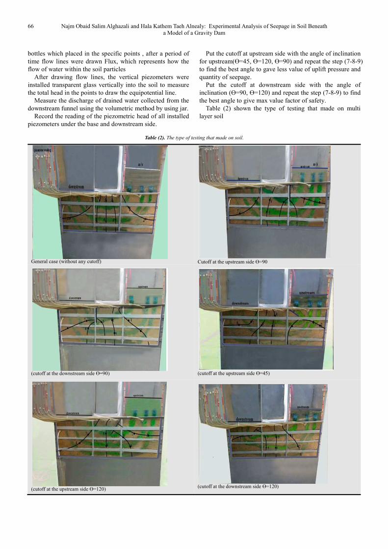
bottles which placed in the specific points , after a period of
time flow lines were drawn Flux, which represents how the
flow of water within the soil particles
After drawing flow lines, the vertical piezometers were
installed transparent glass vertically into the soil to measure
the total head in the points to draw the equipotential line.
Measure the discharge of drained water collected from the
downstream funnel using the volumetric method by using jar.
Record the reading of the piezometric head of all installed
piezometers under the base and downstream side.
Put the cutoff at upstream side with the angle of inclination
for upstream(Ɵ=45, Ɵ=120, Ɵ=90) and repeat the step (7-8-9)
to find the best angle to gave less value of uplift pressure and
quantity of seepage.
Put the cutoff at downstream side with the angle of
inclination (Ɵ=90, Ɵ=120) and repeat the step (7-8-9) to find
the best angle to give max value factor of safety.
Table (2) shown the type of testing that made on multi
layer soil
Table (2). The type of testing that made on soil.
General case (without any cutoff)
Cutoff at the upstream side Ɵ=90
(cutoff at the downstream side Ɵ=90)
(cutoff at the upstream side Ɵ=45)
(cutoff at the upstream side Ɵ=120)
(cutoff at the downstream side Ɵ=120)

American Journal of Civil Engineering 2015;
4. The Results and Discussions
Herein, the discussions of the results for single layer
(sandy silty clay ) according the following parameters
4.1. Effect of Inclination Cutoff and its Position
Uplift Head
As shown in figure (2). When the Cutoff in upstream side
of hydraulic structure was inclination with different angles,
its noticed that the uplift pressure underneath the hydraulic
structure decreases as(Ɵ) decreases toward
(45° , 90°,120°) where the maximum redaction in uplift
pressure according to the general case Ɵ=0(without any
cutoff) was (57% , 45% ,22%) respectively so that the best
angle is 45°.
Figure (2). Uplift head ratio through foundation . A range of (Ɵ) values for
cutoff in U/S.
From figure (3). When the Cutoff in downstream side of
hydraulic structure is used, the uplift pressure obtained
decreases as (Ɵ) decreases toward U/S side for Ɵ ( 90°and
120°) and the maximum redaction in uplift pressure
according to the general case Ɵ=0 was (2.3% ,and2.
is noticed that the redaction of the uplift pressure is small to
the replacing of the cut-off ,therefore, it is not suggested at
any angle of inclination.
Figure (3). the value of uplift head for different values of
cutoff in D/S part of structure.
American Journal of Civil Engineering 2015; 3(3): 64-69
Results and Discussions
Herein, the discussions of the results for single layer
(sandy silty clay ) according the following parameters:
Position on the
the Cutoff in upstream side
cture was inclination with different angles,
its noticed that the uplift pressure underneath the hydraulic
structure decreases as(Ɵ) decreases toward U/S side for Ɵ
redaction in uplift
se Ɵ=0(without any
cutoff) was (57% , 45% ,22%) respectively so that the best
range of (Ɵ) values for
When the Cutoff in downstream side of
hydraulic structure is used, the uplift pressure obtained
U/S side for Ɵ ( 90°and
120°) and the maximum redaction in uplift pressure
according to the general case Ɵ=0 was (2.3% ,and2.74%). It
is noticed that the redaction of the uplift pressure is small to
off ,therefore, it is not suggested at
for different values of (Ɵ) values for
When the cutoff positioned in U/S and
structure as shown figure(4), the uplift reduced strongly and
value of redaction is 38% as compared with general case
(Ɵ=0) .
Figure (4). Uplift head ratio through foundation
cutoff in U/S and D/S.
4.2. Effect of inclination Cutoff
Gradient
The exit gradient was studied at the end of the hydraulic
structure for the cases that will be discussed herein and the
results are represented graphically
each angle of inclination must be calculated where is equal to
the division of exit gradient on critical gradient (Icr) which is
dependent on the specific gravity (Gs) and void ratio (e) of
the soil particles [ Icr =(Gs-1)/(1+e)]. In this study and
this type of soil (Gs =2.75 ,e =0.77, Icr =0.988
In figure(5) when the cutoff put in upstream side of
hydraulic structure it is found that the redaction in values of
exit gradient were so small and as follows for Ɵ(45°,9
where the maximum redaction in
case Ɵ=0(without any cutoff) was (1.2% , 1.87% ,2.47%)
respectively
The result shows that the upstream cut
angle has no noticed effect on exit gradient. From the result
the factor of safety against piping for this case were shown in
table (3).
Figure (5). Exit gradient a range of (Ɵ) values for cutoff in U/S part of
structure.
67
When the cutoff positioned in U/S and D/S part of
), the uplift reduced strongly and
value of redaction is 38% as compared with general case
foundation a range of (Ɵ) values for
Cutoff and its Position on the Exit
The exit gradient was studied at the end of the hydraulic
structure for the cases that will be discussed herein and the
raphically. The factor of safety for
each angle of inclination must be calculated where is equal to
the division of exit gradient on critical gradient (Icr) which is
dependent on the specific gravity (Gs) and void ratio (e) of
1)/(1+e)]. In this study and for
soil (Gs =2.75 ,e =0.77, Icr =0.988).
the cutoff put in upstream side of
hydraulic structure it is found that the redaction in values of
exit gradient were so small and as follows for Ɵ(45°,90°,120°)
redaction in according to the general
case Ɵ=0(without any cutoff) was (1.2% , 1.87% ,2.47%)
The result shows that the upstream cut-off inclination
angle has no noticed effect on exit gradient. From the result
ctor of safety against piping for this case were shown in
a range of (Ɵ) values for cutoff in U/S part of
68 Najm Obaid Salim Alghazali and Hala Kathem Taeh Alnealy:
Table (3). The factor of safety against piping when cutoff at
U/S Cut-off Inclination Max (exist gradient)
0º 0.4
45º 0.382 90º 0.375
120º 0.362
In figure(6) when the cutoff is put it in downstream side of
hydraulic structure the exit gradient decreases as (Ɵ)
increases toward the D/S side for Ɵ ( 90° and 120°) the
maximum redaction in exist gradient according to the general
case Ɵ=0 was (12.5% and 25% ), respectively . So that the
factor of safety against piping phenomenon of this case can
be calculated as shown in table (4).These results show that
using cutoff in D/S side inclination toward D/S Ɵ=120
increasing the factor of safety against piping
Figure (6). Exit gradient a range of (Ɵ) values for cutoff in U/S part of
structure.
Table (4). The factor of safety against piping when cutoff at
U/S Cut-off Inclination Max (exist gradient)
0º 0.4
90º 0.35
120º 0.31
When the Cutoff in up and down stream side of structure
the exit gradient in the bed level of structure decreases
compare with general case as shown in figure (7
Figure (7). Exit gradient a range of (Ɵ) values for cutoff in U/S part of
structure.
Najm Obaid Salim Alghazali and Hala Kathem Taeh Alnealy: Experimental Analysis of Seepage in Soil Beneath
a Model of a Gravity Dam
The factor of safety against piping when cutoff at U/S.
Fs
2.47
2.586 2.63 2.729
the cutoff is put it in downstream side of
hydraulic structure the exit gradient decreases as (Ɵ)
increases toward the D/S side for Ɵ ( 90° and 120°) the
according to the general
=0 was (12.5% and 25% ), respectively . So that the
against piping phenomenon of this case can
).These results show that
inclination toward D/S Ɵ=120
factor of safety against piping.
a range of (Ɵ) values for cutoff in U/S part of
The factor of safety against piping when cutoff at U/S.
(exist gradient) Fs
2.47
2.82 3.18
the Cutoff in up and down stream side of structure
the exit gradient in the bed level of structure decreases
al case as shown in figure (7).
a range of (Ɵ) values for cutoff in U/S part of
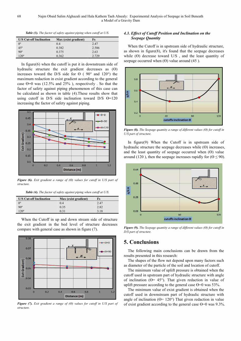
4.3. Effect of Cutoff Position and
Seepage Quantity
When the Cutoff is in upstream side of hydraulic st
as shown in figure(8), it's found that the seepag
while (Ɵ) decrease toward U/S , and the least quantity of
seepage occurred when (Ɵ) value around (45 ).
Figure (8). The Seepage quantity a range of different values (Ɵ)
U/S part of structure.
In figure(9) When the Cutoff is in
hydraulic structure the seepage decreases while (Ɵ) increases,
and the least quantity of seepage occurred when (Ɵ) value
around (120 ), then the seepage increases rapidly for (Ɵ ≤ 90).
Figure (9). The Seepage quantity a range of differen
D/S part of structure.
5. Conclusions
The following main conclusions can be drawn from the
results presented in this research
The shapes of the flow net depend upon many factors such
as diameter of the particle of the soil and
The minimum value of uplift pressure is obtained when the
cutoff used in upstream part of hydraulic structure
of inclination (Ɵ= 45°). That given redaction
uplift pressure according to the general case Ɵ=0 was 53%
The minimum value of exist gradient is obtained when the
cutoff used in downstream part of hydraulic structure
angle of inclination (Ɵ= 120°) That given redaction in value
of exist gradient according to the general case Ɵ=0 was 9.3%.
Experimental Analysis of Seepage in Soil Beneath
and Inclination on the
is in upstream side of hydraulic structure,
), it's found that the seepage decreases
U/S , and the least quantity of
seepage occurred when (Ɵ) value around (45 ).
a range of different values (Ɵ) for cutoff in
the Cutoff is in upstream side of
hydraulic structure the seepage decreases while (Ɵ) increases,
and the least quantity of seepage occurred when (Ɵ) value
around (120 ), then the seepage increases rapidly for (Ɵ ≤ 90).
a range of different values (Ɵ) for cutoff in
The following main conclusions can be drawn from the
results presented in this research:
depend upon many factors such
as diameter of the particle of the soil and location of cutoff.
The minimum value of uplift pressure is obtained when the
cutoff used in upstream part of hydraulic structure with angle
(Ɵ= 45°). That given redaction in value of
uplift pressure according to the general case Ɵ=0 was 53%.
The minimum value of exist gradient is obtained when the
cutoff used in downstream part of hydraulic structure with
(Ɵ= 120°) That given redaction in value
according to the general case Ɵ=0 was 9.3%.

American Journal of Civil Engineering 2015; 3(3): 64-69 69
And increasing the factor of safety against piping to 2.06.
Placing the cutoff at the dam heel (cutoff U/S side) to
reduce the piping phenomenon in downstream side is not
recommended under any angle of inclination, because such
placement has too small effect.
The best angle of inclination is 45° towards upstream
where it reduced the uplift pressure to ( 43% according to
general case Ɵ=0) as compared with other type of inclination
and reducing the quantity of seepage.
References
[1] AL-Ganaini, M.A., (1984), “Hydraulic Structure”, Beirut, pp47-60, (In Arabic).
[2] Selim, M.A., (1947) “Dams on Porous Media”, Transaction ASCE, Vol. 1 Roy, S.K. (2010). "Experimental Study On Different Types Of Seepage Flow Under The Sheet Pile Through Indigenous Model.” M.Sc. Thesis Insoil Mechanics and Foundation Engineering, University Of Jadavpur.12, pp 488-526.
[3] Arslan, C. A. And Mohammad, S. A. (2011)."Experimental and Theoretical Study for Pizometric Head Distribution under Hydraulic Structures." Department of Civil engineering; College of engineering, University of kirkuk Volume 6, No.
[4] EL-Fitiany, M. A. Abourohim, R. I. And El-Dakak, A. Y. (2003). "Three dimensional ground water seepage around a simple hydraulic structure." Alexandria Engineering Journal, Volume 42, Issue 5, September.
[5] Roy, S.K. (2010). "Experimental Study On Different Types Of Seepage Flow Under The Sheet Pile Through Indigenous Model.", M.Sc. Thesis Insoil Mechanics and Foundation Engineering, University Of Jadavpur
[6] Aziz, L. J. (2008). “Lateral Resistance of Single Pile Embedded in Sand with Cavities.", D.Ph Thesis, University of Technology, Iraq.
[7] Khasaf, S. I.(1998). "Numerical Analysis of Seepage Problems with Flow Control Devices Underneath Hydraulic Structures." Ph.D. Thesis in Water Resources Engineering, University of Technology.
[8] U.S. Bureau of Reclamation.(1977). " Design of Small Dams." A Water Resources Technical Publication, Washington, DC.
[9] HM 169 (2011). "Drainage and Seepage Tank."Experiment Instructions Equipment for Engineering Education G.U.N.T. Gerätebau GmbH, Barsbüttel, Germany.
[10] Harr, M.E.(1962). "Groundwater and seepage." McGraw-Hill Book Company.