EXPERIMENT MANUAL - thamesandkosmos.com · flow on the underside is due to a higher pressure...
7
EXPERIMENT MANUAL Franckh-Kosmos Verlags-GmbH & Co. KG, Pfizerstr. 5-7, 70184 Stuttgart, Germany | +49 (0) 711 2191-0 | www.kosmos.de Thames & Kosmos, 301 Friendship St., Providence, RI, 02903, USA | 1-800-587-2872 | www.thamesandkosmos.com Thames & Kosmos UK LP, 20 Stone Street, Cranbrook, Kent, TN17 3HE, UK | 01580 713000 | www.thamesandkosmos.co.uk
Transcript of EXPERIMENT MANUAL - thamesandkosmos.com · flow on the underside is due to a higher pressure...

E X PE R I M E NT M A N UA L
Franckh-Kosmos Verlags-GmbH & Co. KG, Pfizerstr. 5-7, 70184 Stuttgart, Germany | +49 (0) 711 2191-0 | www.kosmos.de Thames & Kosmos, 301 Friendship St., Providence, RI, 02903, USA | 1-800-587-2872 | www.thamesandkosmos.com Thames & Kosmos UK LP, 20 Stone Street, Cranbrook, Kent, TN17 3HE , UK | 01580 713000 | www.thamesandkosmos.co.uk

WIND power 2.0 | Contents
Features, Recommendations & Safety Guidelines ................................... 1
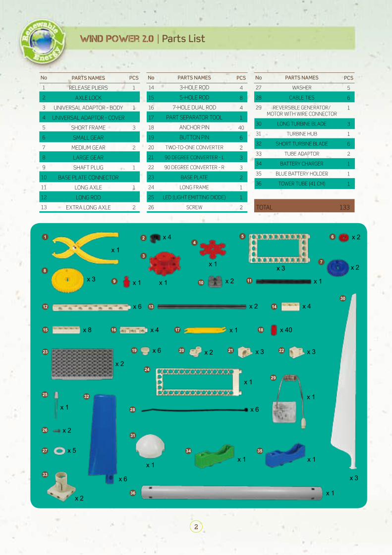
Parts List ................................................................................................................. 2
What is Wind? ........................................................................................................ 3
Wind Strength Scale ........................................................................................... 4
Blade Design and Number ................................................................................ 5
Wind Power ............................................................................................................ 6
Current Generated by a Direct Current Generator ................................... 7
Reversible Generator with Wire Connector ................................................ 8
Tips and Tricks for Building the Models ........................................................ 9
How to Adjust the Gearbox ........................................................................... 10
Indoor Experiments .......................................................................................... 11
Setting up the Windmills ................................................................................ 12
Let’s Do Some Experiments! ......................................................................... 13
Storing the Generated Electricity ............................................................... 14
Advanced Reference ................................................................................. 15-19
MODEL 1 Windmill with Long Blades .................................................. 20-22
MODEL 2 Windmill with Short Blades ................................................. 23-25
MODEL 3 Glider .......................................................................................... 26-27
MODEL 4 Sail Car ........................................................................................ 28-29
MODEL 5 Tricycle ....................................................................................... 30-31
MODEL 6 Jet Car ......................................................................................... 32-33
MODEL 7 Tractor ....................................................................................... 34-35
MODEL 8 Race Car .................................................................................... 36-37
2
WIND power 2.0 | Parts List
PCS
1
4
1
1
3
2
2
3
1
2
1
6
2
No
1
2
3
4
5
6
7
8
9
10
11
12
13
PARTS NAMES
RELEASE PLIERS
AXLE LOCK
UNIVERSAL ADAPTOR - BODY
UNIVERSAL ADAPTOR - COVER
SHORT FRAME
SMALL GEAR
MEDIUM GEAR
LARGE GEAR
SHAFT PLUG
BASE PLATE CONNECTOR
LONG AXLE
LONG ROD
EXTRA LONG AXLE
No
14
15
16
17
18
19
20
21
22
23
24
25
26
PARTS NAMES
3-HOLE ROD
5-HOLE ROD
7-HOLE DUAL ROD
PART SEPARATOR TOOL
ANCHOR PIN
BUTTON PIN
TWO-TO-ONE CONVERTER
90 DEGREE CONVERTER - L
90 DEGREE CONVERTER - R
BASE PLATE
LONG FRAME
LED (LIGHT EMITTING DIODE)
SCREW
PCS
4
8
4
1
40
6
2
3
3
2
1
1
2 TOTAL 133
No
27
28
29
30
31
32
33
34
35
36
PARTS NAMES
WASHER
CABLE TIES
REVERSIBLE GENERATOR/MOTOR WITH WIRE CONNECTOR
LONG TURBINE BLADE
TURBINE HUB
SHORT TURBINE BLADE
TUBE ADAPTOR
BATTERY CHARGER
BLUE BATTERY HOLDER
TOWER TUBE (41 CM)
PCS
5
6
1
3
1
6
2
1
1
1
1 24
5 6
7
8
9 10 11
12
15
23 19
24
25
26
27
28
32
33
36
31
34 35
20 21 22
29
16 17 18
13 14
30
3x 1
x 1 x 1 x 1
x 1
x 1
x 1
x 1
x 1x 1
x 1
x 1
x 6
x 6
x 6
x 6
x 5
x 2
x 2
x 2
x 2
x 2
x 2x 4
x 3x 3
x 8 x 4
x 4
x 40
x 2
x 2
x 1
x 3
x 3x 3
5
Blade Design and Number | WIND power 2.0
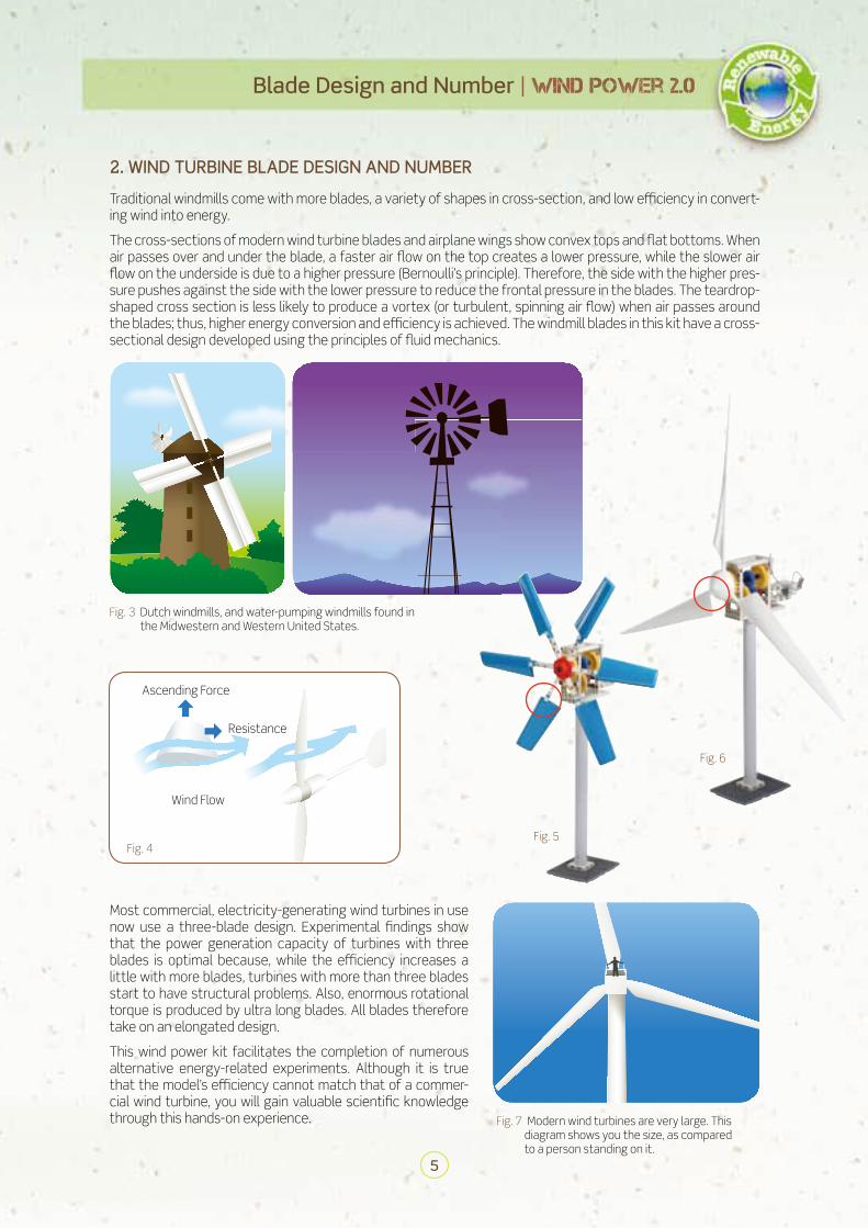
2. WIND TURBINE BLADE DESIGN AND NUMBER
Most commercial, electricity-generating wind turbines in use now use a three-blade design. Experimental findings show that the power generation capacity of turbines with three blades is optimal because, while the efficiency increases a little with more blades, turbines with more than three blades start to have structural problems. Also, enormous rotational torque is produced by ultra long blades. All blades therefore take on an elongated design.
This wind power kit facilitates the completion of numerous alternative energy-related experiments. Although it is true that the model’s efficiency cannot match that of a commer-cial wind turbine, you will gain valuable scientific knowledge through this hands-on experience. Fig. 7 Modern wind turbines are very large. This
diagram shows you the size, as compared to a person standing on it.
Ascending Force
Resistance
Wind Flow
Fig. 4
Traditional windmills come with more blades, a variety of shapes in cross-section, and low efficiency in convert-ing wind into energy.
The cross-sections of modern wind turbine blades and airplane wings show convex tops and flat bottoms. When air passes over and under the blade, a faster air flow on the top creates a lower pressure, while the slower air flow on the underside is due to a higher pressure (Bernoulli’s principle). Therefore, the side with the higher pres-sure pushes against the side with the lower pressure to reduce the frontal pressure in the blades. The teardrop-shaped cross section is less likely to produce a vortex (or turbulent, spinning air flow) when air passes around the blades; thus, higher energy conversion and efficiency is achieved. The windmill blades in this kit have a cross-sectional design developed using the principles of fluid mechanics.
Fig. 3 Dutch windmills, and water-pumping windmills found in the Midwestern and Western United States.
Fig. 5
Fig. 6

6
WIND power 2.0 | Wind Power
3. WIND POWERED ELECTRIC GENERATORS
Wind is a clean and favorable source of sustainable energy with few drawbacks. Because wind is clean and re-newable, and wind turbine technology has reached a practical efficiency, people around the world have started to manufacture more and more wind turbines for commercial use, making wind the fastest growing renewable energy source. When wind turns windmill blades, torque is generated to turn the gearbox, power the generator, and then create electricity. The process shows how wind power is converted into mechanical power, and then turned into electrical power through generators. For home use, the electrical power needs a further transfor-mation by transformers, and is finally distributed to consumers via the electrical grid. The real-world wind power generator uses an alternating current (AC) generator. Its electrical power has to be rectified into direct current (DC) when stored in a battery.
According to Fleming’s right hand rule, when the right index finger is pointing to-wards a magnetic field, the thumb is meanwhile indicat-ing the direction of motion of the conductor, and the middle finger is showing the direction of the electrical current (positive charge of current). This is the principle behind power generator.
Fig. 8 Fig. 9
4. DIRECT CURRENT GENERATOR
Fig. 10 The biggest difference between a direct current generator and an alternating current generator is the commutator connecting the coil, also known as the “brush” structure.
MotionFlux
EMFdirection
Flux direction
Motion direction
Current direction
Right handThumb, index and middle fingers mutually at right angles
1
2
4
56
7 89
3
10
11
12
13
14
15
BladesRotorPitchBrakeLow-speed shaftGear boxGeneratorControllerAnemometerWind VaneNacelleHigh-speed shaftYaw driveYaw motorTower
1.2.3.4.5.6.7.8.9.
10.11.12.13.14.15.
How Wind Power Works
Tower
Transformer
Rotor Blade
Nacelle
Hub
Rotor Hub Gearbox
Brake Brake Generator
Low-speedShaft
High-speedShaft
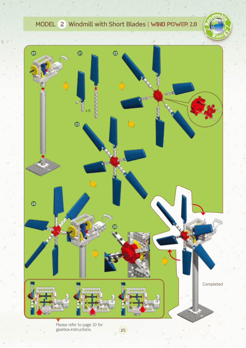
25
MODEL 2 Windmill with Short Blades | WIND power 2.0
20 21 22
23
24
25
x 6
Completed
Please refer to page 10 for gearbox instructions.

27
MODEL 3 Glider | WIND power 2.0
79
1112
14
13
8
10
19
16 17
18
Completed
15