EXPERIMENT 4 POWDER X-RAY DIFFRACTION: STRUCTURAL DETERMINATION OF
78
Crystal Structure Analysis X-ray Diffraction Electron Diffraction Neutron Diffraction Essence of diffraction: Bragg Diffraction Reading: West 5 A/M 5-6 G/S 3 217
Transcript of EXPERIMENT 4 POWDER X-RAY DIFFRACTION: STRUCTURAL DETERMINATION OF
Crystal Structure Analysis
X-ray Diffraction
Electron Diffraction
Neutron Diffraction
Essence of diffraction: Bragg Diffraction
Reading: West 5A/M 5-6G/S 3
217

Elements of Modern X-ray Physics, 2nd Ed. by Jens Als-Nielsen and Des McMorrow, John Wiley & Sons, Ltd., 2011 (Modern x-ray physics & new developments)
X-ray Diffraction, by B.E. Warren, General Publishing Company, 1969, 1990 (Classic X-ray physics book)
Elements of X-ray Diffraction, 3rd Ed., by B.D. Cullity, Addison-Wesley, 2001 (Covers most techniques used in traditional materials characterization)
High Resolution X-ray Diffractometry and Topography, by D. Keith Bowen and Brian K. Tanner, Taylor & Francis, Ltd., 1998 (Semiconductors and thin film analysis)
Modern Aspects of Small-Angle Scattering, by H. Brumberger, Editor, Kluwer Academic Publishers, 1993 (SAXS techniques)
Principles of Protein X-ray Crystallography, 3rd Ed. by Jan Drenth, Springer, 2007 (Crystallography)
REFERENCES
218

SCATTERING
Elastic (E’ = E)
X-rays scatter by interaction with the electron density of a material.Neutrons are scattered by nuclei and by any magnetic moments in a sample.
Electrons are scattered by electric/magnetic fields.
Scattering is the process in which waves or particles are forced to deviate from a straight trajectory because of scattering centers in the propagation medium.
p' p q E' E h Momentum transfer: Energy change:
Inelastic (E’ ≠ E)
q 2 sin2
p
Elastic scattering geometry• Rayleigh (λ >> dobject)• Mie (λ ≈ dobject)• Geometric (λ << dobject)• Thompson (X-rays)
E pcFor X-rays:
• Compton (photons + electrons)• Brillouin (photons + quasiparticles)• Raman (photons + molecular vib./rot.)
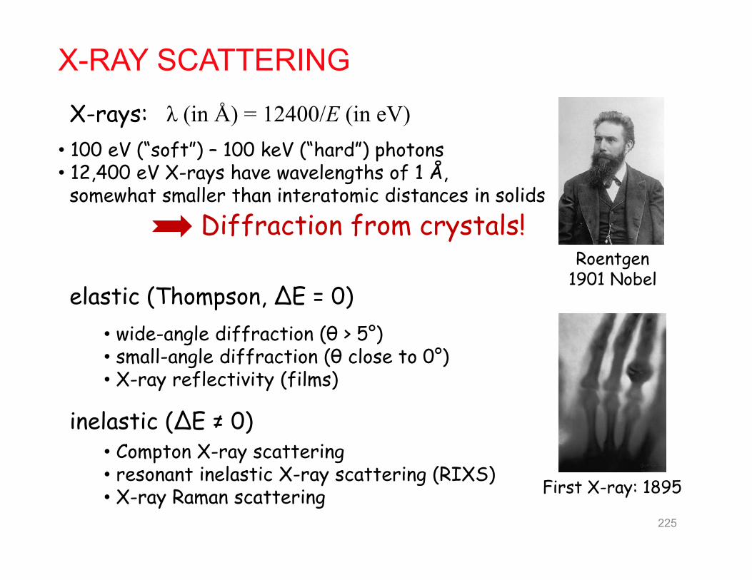
X-RAY SCATTERING
• wide-angle diffraction (θ > 5°)• small-angle diffraction (θ close to 0°)• X-ray reflectivity (films)
elastic (Thompson, ΔE = 0)
inelastic (ΔE ≠ 0)• Compton X-ray scattering• resonant inelastic X-ray scattering (RIXS)• X-ray Raman scattering
X-rays:• 100 eV (“soft”) – 100 keV (“hard”) photons• 12,400 eV X-rays have wavelengths of 1 Å,
somewhat smaller than interatomic distances in solidsDiffraction from crystals!
First X-ray: 1895
Roentgen1901 Nobel
λ (in Å) = 12400/E (in eV)
225

DIFFRACTIONDiffraction refers to the apparent bending of waves around small objects and the
spreading out of waves past small apertures.
In our context, diffraction is the scattering of a coherent wave by the atoms in a crystal. A diffraction pattern results from interference of the scattered waves.
Refraction is the change in the direction of a wave due to a change in its speed.
W. L. BraggW. H. Bragg
diffraction of plane waves
von Laue
Crystal diffractionI. Real space description (Bragg)II. Momentum (k) space description
(von Laue)
226

OPTICAL INTERFERENCE
δ = nλ, n = 0, 1, 2, …
δ = nλ, n = 1/2, 3/2, …
δ: phase differencen: order
perfectly in phase:
perfectly out of phase:

BRAGG’S LAW OF DIFFRACTIONWhen a collimated beam of X-rays strikes pair of parallel lattice planes in a crystal,
each atom acts as a scattering center and emits a secondary wave. All of the secondary waves interfere with each other to produce the diffracted beam
Bragg provided a simple, intuitive approach to diffraction:
• Regard crystal as parallel planes of atoms separated by distance d• Assume specular reflection of X-rays from any given plane→ Peaks in the intensity of scattered radiation will occur when rays
from successive planes interfere constructively
2Θ228

BRAGG’S LAW OF DIFFRACTION
AC sind
ACB 2 sind
ACBn
2 sinn d Bragg’s Law:
When Bragg’s Law is satisfied, “reflected” beams are in phase and interfere constructively. Specular “reflections” can
occur only at these angles.
No peak is observed unless the condition for constructive interference(δ = nλ, with n an integer) is precisely met:
229

DIFFRACTION ORDERS
1st order:
12 sind
2nd order:
22 2 sind
By convention, we set the diffraction order = 1 for XRD. For instance, when n=2 (as above), we just halve the d-spacing to make n=1.
22 2 sind 22( / 2)sind e.g. the 2nd order reflection of d100 occurs at same θ as 1st order reflection of d200
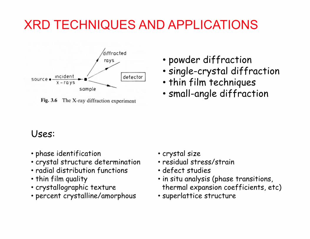
XRD TECHNIQUES AND APPLICATIONS
• powder diffraction• single-crystal diffraction• thin film techniques• small-angle diffraction
• phase identification• crystal structure determination • radial distribution functions• thin film quality• crystallographic texture• percent crystalline/amorphous
• crystal size• residual stress/strain• defect studies • in situ analysis (phase transitions, thermal expansion coefficients, etc)
• superlattice structure
Uses:

POWDER X-RAY DIFFRACTION• uses monochromatic radiation, scans angle• sample is powder → all orientations simultaneously presented to beam• some crystals will always be oriented at the various Bragg angles• this results in cones of diffracted radiation• cones will be spotty in coarse samples (those w/ few crystallites)
crystallite
no restriction on rotational orientation
relative to beam
232
2 sinhkl hkld

233
Transmissiongeometry

DEBYE-SCHERRER METHOD
…or we can use a diffractometer to intercept sections of the cones
234
2 sinhkl hkld

BASIC DIFFRACTOMETER SETUP
235

THETA-2THETA GEOMETRY
• X-ray tube stationary• sample moves by angle theta, detector by 2theta
238

POWDER DIFFRACTOGRAMS
increasing θ, decreasing dMinimum d?
min / 2d
In powder XRD, a finely powdered sample is probed with monochromatic X-rays of a known wavelength in order to evaluate the d-spacings according to Bragg’s Law.
Cu Kα radiation: λ = 1.54 Å
peak positions depend on:• d-spacings of {hkl}• “systematic absences”
240

ACTUAL EXAMPLE: PYRITE THIN FILMFeS2 – cubic (a = 5.43 Å) Random crystal orientations
On casual inspection, peaks give us d-spacings, unit cell size, crystal symmetry, preferred orientation, crystal size, and impurity phases (none!)
111
200210 211 220 311
Cu Kα = 1.54 Å
2 Theta
Inte
nsity
“powder pattern”
2θ = 28.3° → d = 1.54/[2sin(14.15)] = 3.13 Å = d111
reference pattern from ICDD(384,000+ datasets)

d-SPACING FORMULAS
242
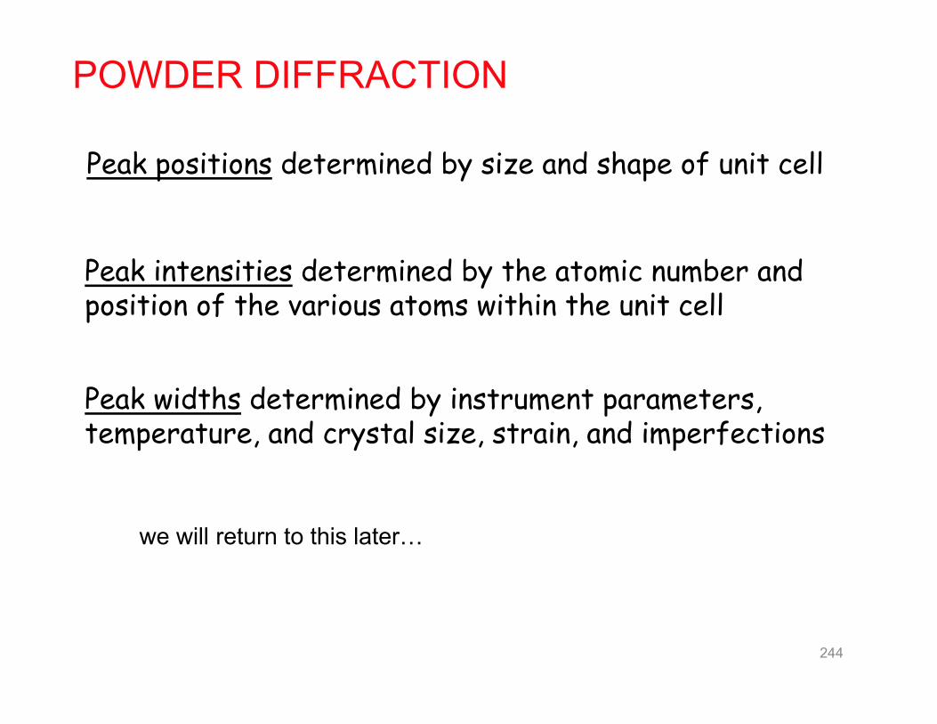
POWDER DIFFRACTION
Peak positions determined by size and shape of unit cell
Peak intensities determined by the atomic number and position of the various atoms within the unit cell
Peak widths determined by instrument parameters, temperature, and crystal size, strain, and imperfections
244
we will return to this later…

GENERATION OF X-RAYSX-rays beams are usually generated by colliding high-energy electrons with metals.
2p3/2 → 1s
Siegbahn notation
X-ray emission spectrum
+ HEAT

246
Generating Bremsstrahlung
Generating Characteristic X-rays

GENERATION OF X-RAYS
Co Kα1 : 1.79 ÅCu Kα1 : 1.54 Å (~8 keV)Mo Kα1 : 0.71 Å
/hchE
Side-window Coolidge X-ray tube
X-ray energy is determined by anode material, accelerating voltage, and monochromators:
1/2 ( )C Z Moseley’s Law:247

SYNCHROTRON LIGHT SOURCES
SOLEIL
• brightest X-ray sources• high collimation• tunable energy• pulsed operation
GeV electron accelerators
249
Bremsstrahlung (“braking radiation”)

MONOCHROMATIC X-RAYSFilters (old way)
A foil of the next lightest element (Ni in the case of Cu anode) can often be used to absorb the unwanted higher-energy radiation to give a clean Kα beam
Crystal MonochromatorsUse diffraction from a curvedcrystal (or multilayer) to selectX-rays of a specific wavelength
250

DETECTION OF X-RAYS
• Point detectors
• Strip detectors
• Area detectors
Detection principles• gas ionization• scintillation• creation of e-h pairs
251

DETECTION OF X-RAYS
Gas proportional counters
Point detectors
252
Scintillation counters

X-RAY DETECTORSArea detectors
Charge-coupled devices
• film• imaging plate• CCD• multiwire
253

X-RAY DETECTORSImaging plates
254
photostimulated luminescencefrom BaFBr0.85I0.15:Eu2+

X-RAY DETECTORSImaging plates
255
photostimulated luminescencefrom BaFBr0.85I0.15:Eu2+
tetragonal Matlockite structure9-coordinate Ba!

The Reciprocal Lattice and the Laue Description of Diffraction
256
Reading: A/M 5-6G/S 3

PLANE WAVESA wave whose surfaces of constant phase are infinite parallel planes of equal spacing normal to the direction of propagation.
ψ: wave amplitude at point rA: max amplitude of wavek: wave vector r: space vector from arbitrary origin
k
|k|=2π/λ
Amplitude is constant in any plane normal to k because k•r is a constant for such planes:
k•r1 = kr1
k•r2 = kr1√2(cos45) = kr1
k
r2
wavefront
origin
k
r1 45°
k•r is indeed constant on wavefronts

THE RECIPROCAL LATTICEThe reciprocal lattice of a Bravais lattice is the set of all vectors K such that
for all real lattice position vectors R. 1ie K R
R = n1a1 + n2a2 + n3a3 Direct lattice position vectors:
Reciprocal lattice vectors:
2
2 3
11 2 3
a aba a a
K = hb1 + kb2 + lb3
2
3 1
21 2 3
a aba a a
2
1 2
31 2 3
a aba a a
where the primitive vectors of the reciprocal lattice are:
and {ni} and {h,k,l} are integers
Reciprocal lattice: The set of all wave vectors K that yield plane waves with the periodicity of a given Bravais lattice.
258

is satisfied when K•R = 2πn, with n an integer
To verify that the {bi} are primitive vectors of the reciprocal lattice, let’s first show that bi•aj = 2πδij
2 2 2
1 2 32 31 1 1
1 2 3 1 2 3
a a aa ab a aa a a a a a
2 0
3 1
2 1 11 2 3
a ab a aa a a
2 0
1 2
3 1 11 2 3
a ab a aa a a
Indeed, bi•aj = 2πδij
so, K•R = (hb1 + kb2 + lb3)•(n1a1 + n2a2 + n3a3)= 2π(hn1 + kn2 + ln3) = 2π × integer
(since cross product of two vectors is perpendicular to both)
K is indeed a reciprocal lattice vector

WHAT IS A RECIPROCAL LATTICE VECTOR?The reciprocal lattice is defined at the lattice generated from the set of all
vectors K that satisfy
for all direct lattice position vectors R. 1ie K R
What is K?a wave vector of a plane wave that has the periodicity of the direct lattice
The direct lattice is periodic (invariant under translation by R)
Reciprocal lattice vectors = wave vectors of plane waves that are unity at all direct lattice sites 260

THE RECIPROCAL LATTICE• the reciprocal lattice is defined in terms of a Bravais lattice
• the reciprocal lattice is itself one of the 14 Bravais lattices
• the reciprocal of the reciprocal lattice is the original direct lattice
e.g., simple cubic direct lattice
ˆa1a x ˆa2a y ˆa3a z
2
3
2ˆ ˆ2 2 aa a
2 31
1 2 3
a ab x xa a a
2 ˆa
2b y 2 ˆa
3b z → simple cubic reciprocal latticewith lattice constant 2π/a
→ b1 parallel to a1, etc. 261

Crystals with orthogonal axes (cubic, tetragonal, orthorhombic)
b1, b2, b3 are parallel to a1, a2, a3, respectively.
b3
a3
b1 a1
a2
b2
reciprocal lattice
direct lattice 2 ˆb
2b y
2 ˆa
1b x
2 ˆc
3b z
ˆa1a x ˆb2a y ˆc3a z
262

RECIPROCAL LATTICE OF FCC IS BCC
FCC primitive vectors:
2
3
ˆ ˆ ˆ( ) 4 14 ˆ ˆ ˆ2 2 ( )2(2)
8
a
a a
2 3
11 2 3
y z - xa ab y z - xa a a
Note: not orthogonal
4 1 ˆ ˆ ˆ( + )2a
2b z x - y 4 1 ˆ ˆ ˆ( + )
2a
3b x y - z
→ BCC reciprocal lattice with lattice constant 4π/a 263

RECIPROCAL LATTICE OF BCC IS FCC
BCC primitive vectors (not orthogonal):
2
3
ˆ ˆ(2 2 ) 4 14 ˆ ˆ2 2 ( )2(4)
8
a
a a
2 3
11 2 3
y za ab y za a a
4 1 ˆ ˆ( )2a
2b z + x 4 1 ˆ ˆ( )
2a
3b x + y
→ FCC reciprocal lattice with lattice constant 4π/a 264

RECIPROCAL LATTICES
• simple orthorhombic → simple orthorhombic
• FCC → BCC
• BCC → FCC
• simple hexagonal → simple hexagonal (rotated)
265

FIRST BRILLOUIN ZONESThe Wigner-Seitz cell of the reciprocal lattice is called the first Brillouin zone
(FBZ).
Wigner-Seitz cell: primitive cell with lattice point at its center
enclosed region is W-S cellfor 2D hexagonal lattice
d.l. FCCr.l. BCC
1st Brillouin zone:
truncated octahedronrhombic dodecahedron
d.l. BCCr.l. FCC
1st Brillouin zone:
269

Theorem:For any family of lattice planes separated by distance d, there are reciprocal lattice vectors perpendicular to the planes, the shortest of which has a length of 2π/d.
Conversely, any reciprocal lattice vector K has a family of real-space planes normal to it, separated by d.
hk in 2Dhkl in 3D
here, g = K
K and LATTICE PLANES
275

Orientation of a plane is determined by its normal vector
It is natural to pick the shortest perpendicular reciprocal lattice vector to represent the normal
Miller indices: coordinates of this reciprocal lattice vector
i.e., A plane with Miller indices hkl is normal to the reciprocal lattice vector K = hb1 + kb2 + lb3
→ Definition #2: directions in k-space
(Definition #1 was inverse intercepts in the real lattice)
MILLER INDICES OF LATTICE PLANES
276

Proof that K = hb1 + kb2 + lb3 is normal to (hkl)
h1a
AB
If K = hb1 + kb2 + lb3 is normal to the plane at left, its dot product with any in-plane vector is zero.
Consider vector AB that lies in the plane.
By vector addition,
l3a
k2a
h l AB31 aa
The dot product,
( )h k lh l
AB K = 311 2 3
aa b b b
2 2 0 =So the reciprocal vector formed by using the Miller indices of a plane as its components forms a vector in space that is normal to the Miller plane.
Furthermore, the length of the shortest vector K is equal to 2π/dhkl.
In the figure above, the spacing between the planes is the projection of : onh
KK
1a
2 2hkl
hdh h
KK K K
1a
(hkl)
02
hkl
Kd
K→277
etc.

POWDER (DEBYE-SCHERRER) METHOD• single wavelength • fixed powder sample• equivalent to rotating the reciprocal lattice through all possible
angles about the origin
every point in reciprocal space traces out a shell of radius K
Each shell with radius K < 2kintersects the Ewald sphere to form a circle.
All the diffracted beams from a powder lie on the surface of cones
291

Peak intensities depend on (in large part):1) intensity scattered by individual atoms (form factors)2) the resultant wave from atoms in unit cell (structure factor)
PEAK INTENSITIES
In many cases, the intensity from certain planes (hkl) is zero.
• symmetry of crystal causes complete cancellation of beam“systematic absences”
• happenstance
Possible reasons:
Other factors that affect intensity: • scattering angle• multiplicities• temperature factor• absorption factor• preferred orientation
292

MONOATOMIC BASES
( - ) 2= 1i ' i ne e k k R
up to now we have considered diffraction only from Bravais lattices with single atom bases (i.e., atoms only at the lattice points R).
We found the diffraction condition:
= 1ie K Rwhich is the same as:
( ) iF f e K RK R
RK
The scattering amplitude FK is the sum over the lattice sites:
The scattered intensity is proportional to the absolute square of the amplitude:
where fR(K) is the “atomic form factor” for a given atom (disc. later).
20I I FK K
…this is what is actually measured in an experiment.

Crystals with n atoms in each primitive cell must be further analyzed into a set of scatterers at positions d1, d2 … dn within each primitive cell.
( )( ) jij
jF f e K R+d
KR
K
n-ATOM BASES
( )j j A R R dThe positions of the atoms are:
making the scattering amplitude:
( ) jiij
je f e K dK R
RK
iL e K R
R
( ) jij
jf e K d
K K“Lattice sum”
“Structure factor” of the basis
*If the structure factor = 0, there is no diffraction peak.

( ) jij
jf e K d
K K
The structure factor gives the amplitude of a scattered wave arising from the atoms with a single primitive cell.
STRUCTURE FACTOR
For crystals composed of only one type of atom, it’s common to split the structure factor into two parts:
( )jf S K KK
ji
jS e K d
K
“atomic form factor”
“geometric structure factor”
S = 0 gives a systematic absence (i.e., absence of expected diff. peak).295

2( )hklI S K
1ie K d nie K d…
1
jn
i
jS e
KK
d
The amplitude of the rays scattered at positions d1, …, dnare in the ratios:
The net ray scattered by the entire cell is the sum of the individual rays:
STRUCTURE FACTORS
Geometric structurefactor
-Adds up scatteredwaves from unit cell
-In particular, nopeak when SK = 0
296

For simple cubic: one atom basis (0,0,0)
0 1iS e KK
SIMPLE CUBIC
d1 = 0a1 + 0a2 + 0a3
297
Same result as simple monatomic basis

For monoatomic BCC: we can think of this as SC with two point basis (0,0,0), (½,½,½)
lkh )1(1
S = 2, when h + k + l evenS = 0, when h + k + l odd (systematic absences)
2 ( )0 2
1
( )1
j
ai x y zi i
j
i h k l
S e e e
e
KK K
Kd
MONATOMIC BCC
2 ˆ ˆ ˆ( )h k la
K x y zFor SC,
298

e.g. consider the powder pattern of BCC molybdenum
Powder card shows only even hkl sums b/c Mo is BCCWhy?
- Diffraction from other (hkl) results in destructive interference:
(100)
d100
Beam cancels b/c body center atoms scatter exactly 180° out of phase
(200)
d200
Strong reflection b/c all atoms lie on 200 planes and scatter in phase

S = 4 when h + k, k + l, h + l all even (h, k, l all even or all odd)
S = 0 otherwise.
( ) ( ) ( )1 i h k i k l i h lS e e e K
For monoatomic FCC: SC with four point basis (0,0,0), (½,½,0), (0,½,½), (½,0,½)
4 ( ) ( ) ( )0 2 2 2
1
j
a a ai x y i y z i x zi i
jS e e e e e
K K KK K
Kd
MONATOMIC FCC
2 ˆ ˆ ˆ( )h k la
K x y zFor SC,
300

(hkl) NaCl KCl(100)(110)(111) (200) (210)(211)(220) (221)(300)(310)(311)
Once again, there are more systematic absences for isoelectronic ions (e.g., K and Cl)
(110) always absent in RS
(111) sometimes absent
306

DIAMOND STRUCTUREDiamond: FCC lattice with two-atom basis (0,0,0,), (¼,¼,¼)
( )0 4, ,
( /2)( ),
[ ][ ]
[1 ][ ]
aiK x y ziKdiamond FCC
i h k lFCC
S e e S
e S
K K
K
S = 8 h + k + l twice an even numberS = 4(1 ± i) h + k + l oddS = 0 h + k + l twice an odd number
IFCC : all nonvanishing spots have equal intensity.
Idiamond : spots allowed by FCC have relative intensities of 64, 32, or 0. 308
Only for all even or all odd hkl is S ≠ 0. For these unmixed values,Additional condition:

(hkl) Al Si(100)(110)(111) (200) (210)(211)(220) (221)(300)(310)(311)
What about zinc blende?
FCC diamond
309

SUMMARY OF SYSTEMATIC ABSENCEScrystal structure condition for peak to occur
SC any h,k,lBCC h + k + l = evenFCC h,k,l all even or all odd NaCl h,k,l all even,
or all odd if fA ≠ fB
diamond h,k,l all even and twice an even #, or all odd
HCP any h,k,l except when h + 2k = 3nand l is odd
( ) jij
jf e K d
K K310
eandrei
Callout
sum =h+k+l=4n
eandrei
Callout
and Silicon

Observable diffraction peaks for monoatomic crystals
222 lkh SC: 1,2,3,4,5,6,8,9,10,11,12,…
BCC: 2,4,6,8,10,12,...
FCC: 3,4,8,11,12,16,24,…
SIMPLE ANALYSIS OF SIMPLE PATTERNSWhat will we see in XRD patterns of SC, BCC, FCC?
SC FCC BCC
We can take ratios of (h2 + k2 + l2) to determine structure.
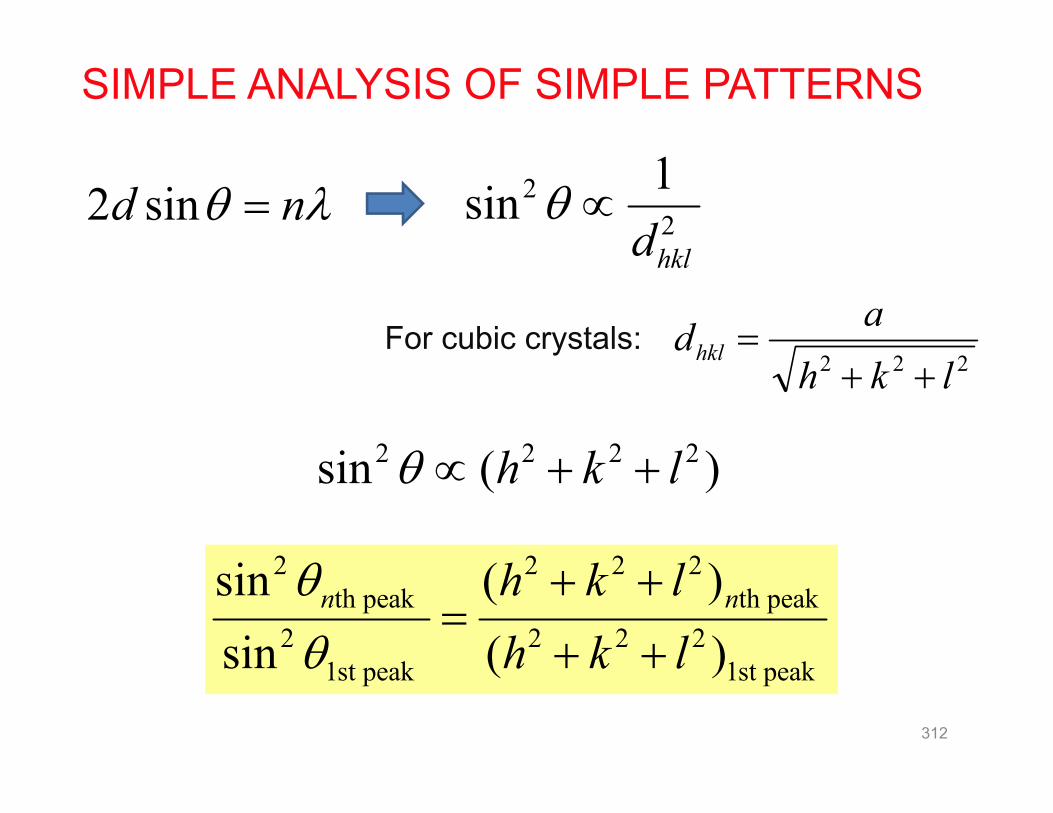
SIMPLE ANALYSIS OF SIMPLE PATTERNS
nd sin2
222 lkhadhkl
For cubic crystals:
22
1sinhkld
2 2 2 2sin ( )h k l
2 2 2 2th peak th peak
2 2 2 21st peak 1st peak
sin ( )sin ( )
n nh k lh k l
312

2 22
2 21
sin sin 33 2sin sin 22
SIMPLE ANALYSIS OF SIMPLE PATTERNS
110
200
211
α-Fe is cubic. Is it FCC or BCC? BCC!
What about Al?
2 22
2 21
sin sin 22.5 1.33sin sin 19
111
200220
311
222 400331 420
FCC!
313

Ex: An element, BCC or FCC, shows diffraction peaks at 2: 40, 58, 73, 86.8,100.4 and 114.7. Determine:(a) Crystal structure?(b) Lattice constant?(c) What is the element?
2theta theta (hkl)
40 20 0.117 1 (110)58 29 0.235 2 (200)73 36.5 0.3538 3 (211)
86.8 43.4 0.4721 4 (220)100.4 50.2 0.5903 5 (310)114.7 57.35 0.7090 6 (222)
2sin 222 lkh
BCC, a =3.18 Å W
normalized
314

ELASTIC X-RAY SCATTERING BY ATOMSAtoms scatter X-rays because the oscillating electric field of an X-ray sets each electron in an atom into vibration. Each vibrating electron acts as a secondary point source of coherent X-rays (in elastic scattering).
Thomson relation:
The X-ray scattered from an atom is the resultant wave from all its electrons
Particle picture:
• zero phase difference for forward/backward scattering→ scattering factor (form factor, f ) proportional to atomic number, Z
• increasingly destructive interference with larger scattering angle (to 90°)• for a given angle, intensity decreases with decreasing X-ray wavelength
• max scattering intensity at 2θ = 0 & 180°• gradual decrease to 50% as 2θ approaches 90°
21 (1 cos 2 )2
I

SCATTERING OF X-RAYS BY ATOMS
Thomson relation: 21 (1 cos 2 )2
I
scattering angle probabilities for a free electron:
Low energy: ThomsonHigh energy: Compton
Klein–Nishina formula
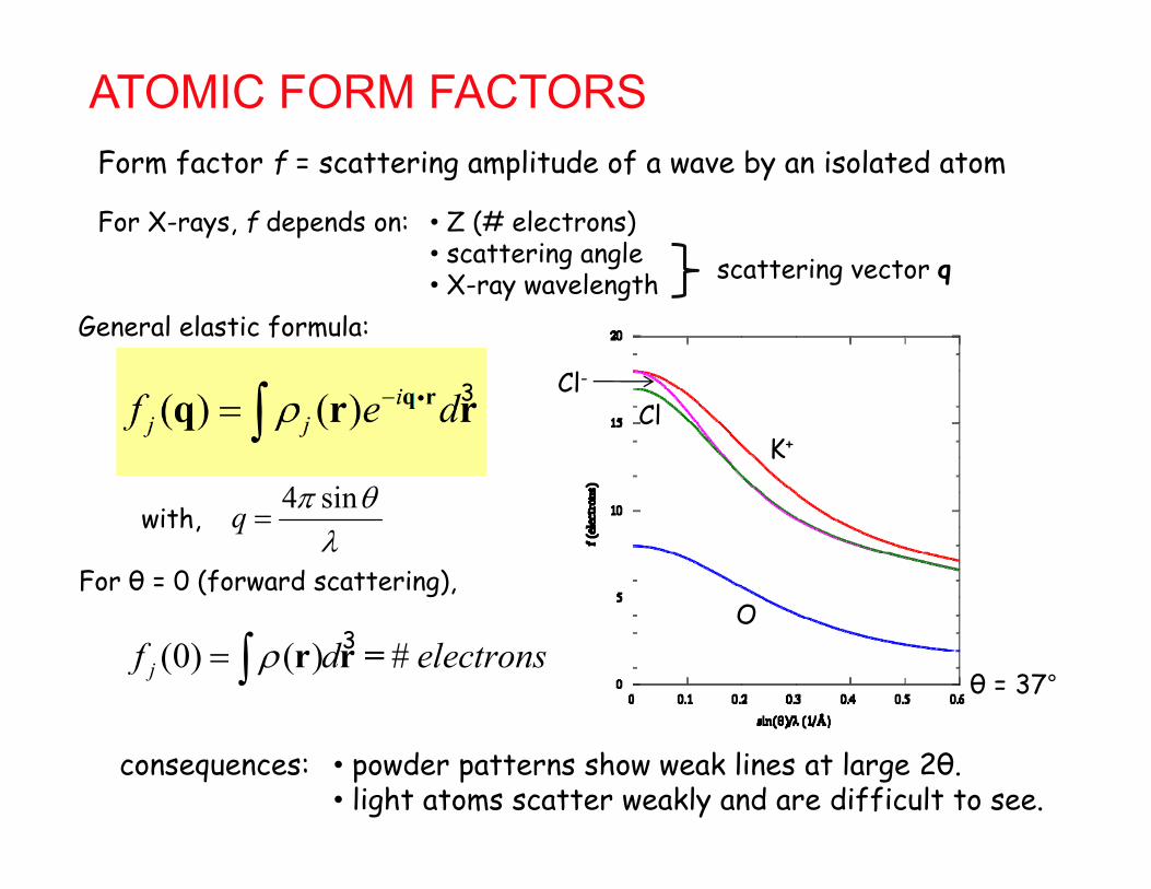
ATOMIC FORM FACTORSForm factor f = scattering amplitude of a wave by an isolated atom
• Z (# electrons)• scattering angle• X-ray wavelength
For X-rays, f depends on:
consequences: • powder patterns show weak lines at large 2θ. • light atoms scatter weakly and are difficult to see.
0
( ) ( ) ij jf e d
q rq r r
4 sinq
with,
For θ = 0 (forward scattering),
scattering vector q
General elastic formula:
0
(0) ( )jf d # electrons
r r =O
K+
Cl-Cl
θ = 37°
3
3

PEAK WIDTHSPeak shape is a Voigt function (mixture of Gaussian and Lorentzian)
Peak width (broadening) is determined by several factors:
• natural linewidth of X-ray emission• instrumental effects (polychromatic λ, focusing, detector)• specimen effects
1) crystallite size2) crystallite strain
• Gaussian component arises from natural linewidth and strain • Lorentzian component arises from coherent domain size
PureLorentzian
PureGaussian
319

320
FULL WIDTH AT HALF MAXIMUM (FWHM)

Instrument and Sample Contributions to the Peak Profile must be Deconvoluted
• In order to analyze crystallite size, we must deconvolute:– Instrumental Broadening FW(I)
• also referred to as the Instrumental Profile, Instrumental FWHM Curve, Instrumental Peak Profile
– Specimen Broadening FW(S)• also referred to as the Sample Profile, Specimen Profile
• We must then separate the different contributions to specimen broadening– Crystallite size and microstrain broadening of diffraction peaks
321

SIZE BROADENINGSmall crystallites (< 200 nm) show broadened diffraction lines
Nanocrystal X-ray Diffraction
322

323

Which of these diffraction patterns comes from a nanocrystalline material?
66 67 68 69 70 71 72 73 74
2 (deg.)
Inte
nsity
(a.u
.)
These diffraction patterns were produced from the same sample!• Two different diffractometers, with different optical configurations, were used• The apparent peak broadening is due solely to the instrumentation in
this case324
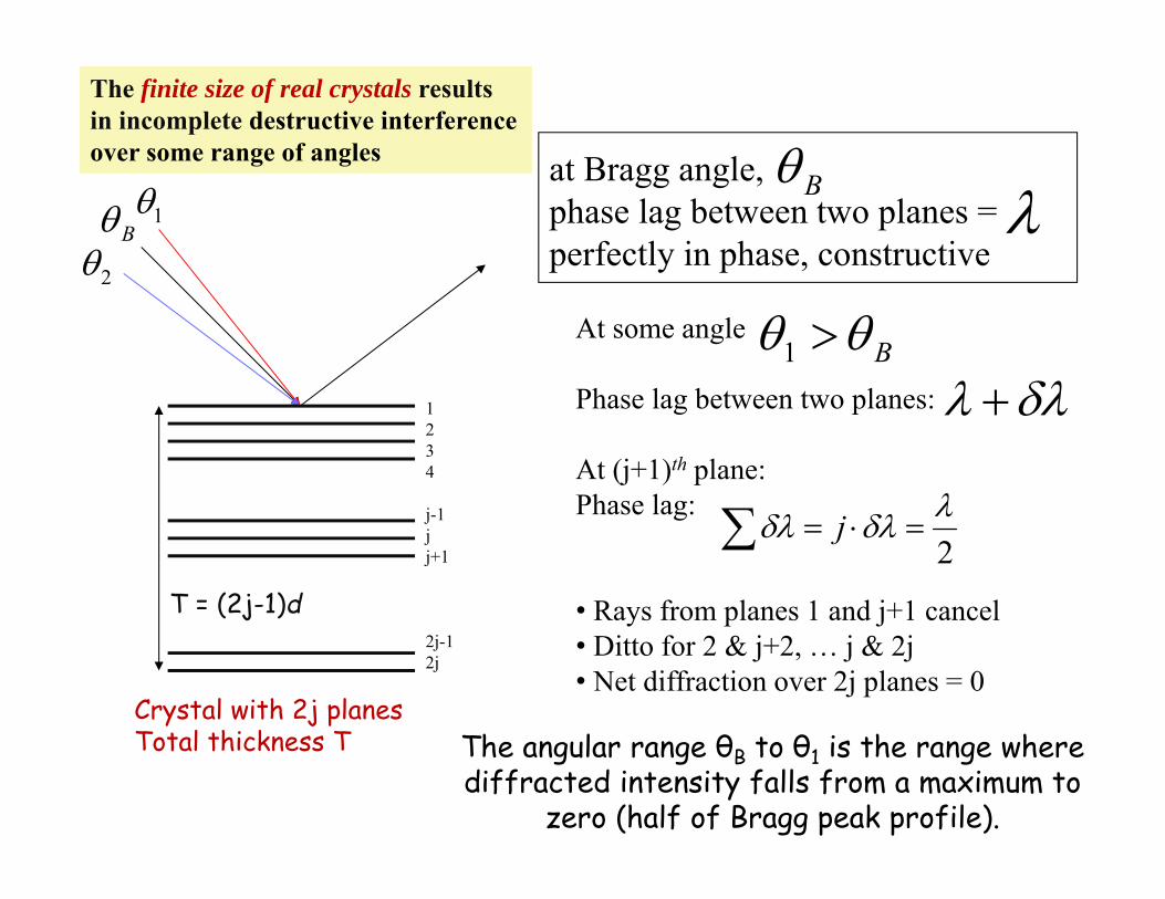
1234
j-1jj+1
2j-12j
B 1
2
at Bragg angle,phase lag between two planes = perfectly in phase, constructive
B
B 1At some angle
Phase lag between two planes:
At (j+1)th plane:Phase lag:
• Rays from planes 1 and j+1 cancel• Ditto for 2 & j+2, … j & 2j• Net diffraction over 2j planes = 0
2 j
The finite size of real crystals resultsin incomplete destructive interferenceover some range of angles
Crystal with 2j planesTotal thickness T
T = (2j-1)d
The angular range θB to θ1 is the range where diffracted intensity falls from a maximum to
zero (half of Bragg peak profile).

Same arguments apply to B 2
So we see diffracted X-rays over all scattering angles between 2θ1and 2θ2.
– If we assume a triangular shape for the peak, the full width athalf maximum of the peak will be B = (2θ1 – 2θ2)/2 = θ1 – θ2
326

If we have more than 2j planes:
1234
j-1jj+1
2j+12j+2
B 1
2
If we have fewer than 2j planes:
1234
j-1jj+1
2j-32j-2
B 1
2
still zero intensity at θ1 nonzero intensity at θ1
Rays from planes j-1 & j not canceledRays from new planes are canceled
Thinner crystals result in broader peaks! 327
Peak sharpens! Peak broadens!

Let’s derive the relation between crystal thickness T and peak width B:
2 sind
1
2
2 sin (2 1)2 sin (2 1)T jT j
1 2(sin sin )T
1 2 1 22 (cos( )sin( ))2 2
T
1 22 (cos )( )) .2BT
cos B
TB
1 22( )2
B
Considering the path length differences between X-rays scattered from the front and back planes of a crystal with 2j+1 planes and total thickness T:
If we subtract them:
Using trig identity:
Since and , 1 2
2 B
1 2 1 2sin( )2 2
But, , so
1 2 1 21 2sin sin 2cos sin
2 2
Here, T = 2jd

cos B
KTB
2 2 2M RB B B
BM: Measured FWHM (in radians)BR: Corresponding FWHM of bulk reference (large grain size, > 200 nm)
Readily applied for crystal size of 2-100 nm.Up to 500 nm if synchrotron is used.
SCHERRER FORMULAA more rigorous treatment includes a unitless shape factor:
Scherrer Formula (1918)T = crystallite thicknessλ (X-ray wavelength, Å)K (shape factor) ~ 0.9 B, θB in radians
Accurate size analysis requires correction for instrument broadening:
329

• The constant of proportionality, K (the Scherrer constant) depends on the how the width is determined, the shape of the crystal, and the size distribution– the most common values for K are:
• 0.94 for FWHM of spherical crystals with cubic symmetry• 0.89 for integral breadth of spherical crystals w/ cubic symmetry• 1, because 0.94 and 0.89 both round up to 1
– K actually varies from 0.62 to 2.08• For an excellent discussion of K, refer to JI Langford and AJC
Wilson, “Scherrer after sixty years: A survey and some new results in the determination of crystallite size,” J. Appl. Cryst. 11(1978) 102-113.
cos B
KTB
SCHERRER CONSTANT
0.94cos B
TB
330

Suppose =1.5 Å, d=1.0 Å, and =49˚. Then for a crystal 1mm in diameter, the width B, due to the small crystaleffect alone, would be about 2x10⁻⁷ radian (10-5 degree),too small to be observable. Such a crystal would containsome 107 parallel lattice planes of the spacing assumedabove.
However, if the crystal were only 50 Å thick, it wouldcontain only 51 planes, and the diffraction curve would bevery broad, namely about 43x10-2 radian (2.46˚), which iseasily measurable.
331
“Incomplete destructive interference at angles slightly off the Bragg angles”

DIFFRACTION FROM DISORDERED SOLIDS
amorphous solids
367