Experience with DMS subsurface instrumentation at … with DMS® subsurface instrumentation at...
38
Workshop Drainage of large rockslides Oslo, 30-31th of January 2017 Experience with DMS ® subsurface instrumentation at Åknes rockslide and new developments Mario Lovisolo CSG Srl - Italy
-
Upload
dinhkhuong -
Category
Documents
-
view
222 -
download
4
Transcript of Experience with DMS subsurface instrumentation at … with DMS® subsurface instrumentation at...
Workshop
Drainage of large rockslides
Oslo, 30-31th of January 2017
Experience with DMS® subsurface instrumentation
at Åknes rockslide
and new developments
Mario Lovisolo
CSG Srl - Italy
OVERVIEW
DMS® Differential Monitoring of Stability
DMS® subsurface instrumentation at Åknes
New developments
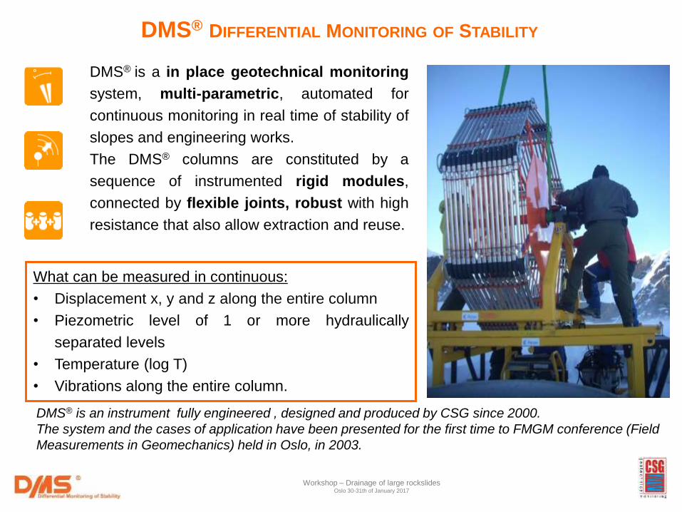
DMS® DIFFERENTIAL MONITORING OF STABILITY
DMS® is a in place geotechnical monitoring
system, multi-parametric, automated for
continuous monitoring in real time of stability of
slopes and engineering works.
The DMS® columns are constituted by a
sequence of instrumented rigid modules,
connected by flexible joints, robust with high
resistance that also allow extraction and reuse.
What can be measured in continuous:
• Displacement x, y and z along the entire column
• Piezometric level of 1 or more hydraulically
separated levels
• Temperature (log T)
• Vibrations along the entire column.
DMS® is an instrument fully engineered , designed and produced by CSG since 2000.
The system and the cases of application have been presented for the first time to FMGM conference (Field
Measurements in Geomechanics) held in Oslo, in 2003.
Workshop – Drainage of large rockslides Oslo 30-31th of January 2017
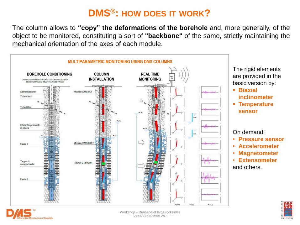
BOREHOLE CONDITIONING COLUMN
INSTALLATION
REAL TIME
MONITORING
DMS®: HOW DOES IT WORK?
The rigid elements
are provided in the
basic version by:
Biaxial
inclinometer
Temperature
sensor
On demand:
• Pressure sensor
• Accelerometer
• Magnetometer
• Extensometer
and others.
The column allows to “copy” the deformations of the borehole and, more generally, of the
object to be monitored, constituting a sort of "backbone" of the same, strictly maintaining the
mechanical orientation of the axes of each module.
Workshop – Drainage of large rockslides Oslo 30-31th of January 2017
MULTIPARAMETRIC MONITORING USING DMS COLUMNS
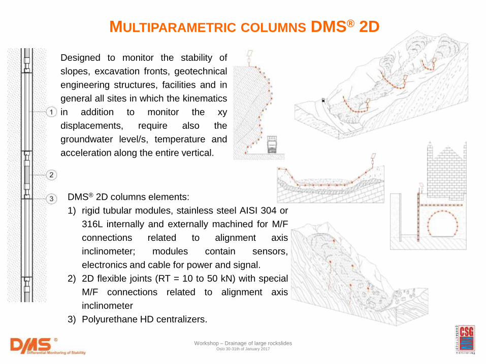
DMS® 2D columns elements:
1) rigid tubular modules, stainless steel AISI 304 or
316L internally and externally machined for M/F
connections related to alignment axis
inclinometer; modules contain sensors,
electronics and cable for power and signal.
2) 2D flexible joints (RT = 10 to 50 kN) with special
M/F connections related to alignment axis
inclinometer
3) Polyurethane HD centralizers.
Designed to monitor the stability of
slopes, excavation fronts, geotechnical
engineering structures, facilities and in
general all sites in which the kinematics
in addition to monitor the xy
displacements, require also the
groundwater level/s, temperature and
acceleration along the entire vertical.
MULTIPARAMETRIC COLUMNS DMS® 2D
Workshop – Drainage of large rockslides Oslo 30-31th of January 2017
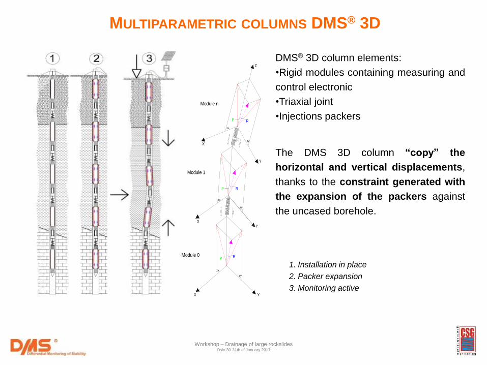
DMS® 3D column elements:
•Rigid modules containing measuring and
control electronic
•Triaxial joint
•Injections packers
The DMS 3D column “copy” the
horizontal and vertical displacements,
thanks to the constraint generated with
the expansion of the packers against
the uncased borehole.
X
Y
zy
zx
RP
XY
zy
zx
X Y
zy
zx
Z
RP
RPModule 0
Module 1
Module n
1. Installation in place
2. Packer expansion
3. Monitoring active
MULTIPARAMETRIC COLUMNS DMS® 3D
Workshop – Drainage of large rockslides Oslo 30-31th of January 2017
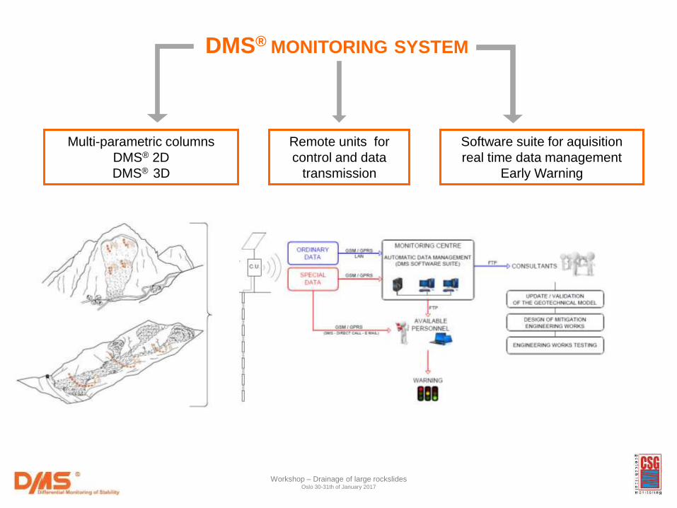
DMS® MONITORING SYSTEM
Multi-parametric columns
DMS® 2D
DMS® 3D
Remote units for
control and data
transmission
Software suite for aquisition
real time data management
Early Warning
Workshop – Drainage of large rockslides Oslo 30-31th of January 2017
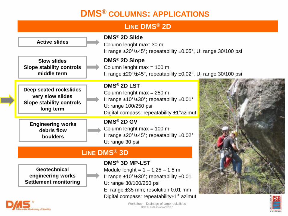
DMS® 2D GV
Column lenght max = 100 m
I: range ±20°/±45°; repeatability ±0.02°
U: range 30 psi
DMS® 3D MP-LST
Module lenght = 1 – 1,25 – 1,5 m
I: range ±10°/±30°; repeatability ±0.01
U: range 30/100/250 psi
E: range ±35 mm; resolution 0.01 mm
Digital compass: repeatability±1° azimut
LINE DMS® 2D
DMS® COLUMNS: APPLICATIONS
LINE DMS® 3D
Active slides
Slow slides
Slope stability controls
middle term
Deep seated rockslides
very slow slides
Slope stability controls
long term
Engineering works
debris flow
boulders
Geotechnical
engineering works
Settlement monitoring
DMS® 2D Slide Column lenght max: 30 m
I: range ±20°/±45°; repeatability ±0.05°, U: range 30/100 psi
DMS® 2D Slope
Column lenght max = 100 m
I: range ±20°/±45°, repeatability ±0.02°, U: range 30/100 psi
DMS® 2D LST
Column lenght max = 250 m
I: range ±10°/±30°; repeatability ±0.01°
U: range 100/250 psi
Digital compass: repeatability ±1°azimut
Workshop – Drainage of large rockslides Oslo 30-31th of January 2017
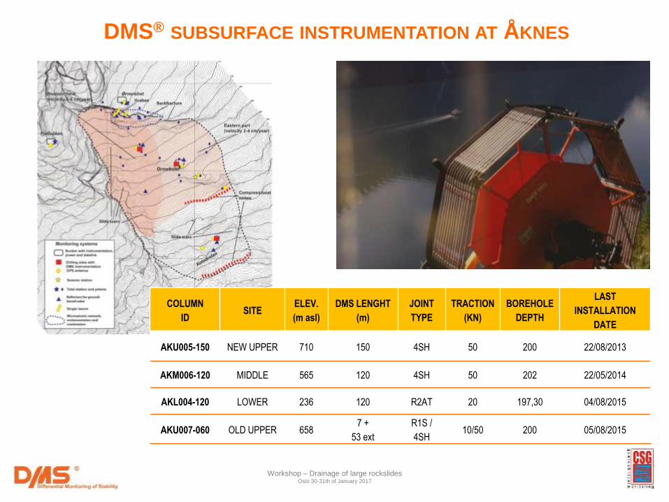
COLUMN
ID SITE
ELEV.
(m asl)
DMS LENGHT
(m)
JOINT
TYPE
TRACTION
(KN)
BOREHOLE
DEPTH
LAST
INSTALLATION
DATE
AKU005-150 NEW UPPER 710 150 4SH 50 200 22/08/2013
AKM006-120 MIDDLE 565 120 4SH 50 202 22/05/2014
AKL004-120 LOWER 236 120 R2AT 20 197,30 04/08/2015
AKU007-060 OLD UPPER 658 7 +
53 ext
R1S /
4SH 10/50 200 05/08/2015
DMS® SUBSURFACE INSTRUMENTATION AT ÅKNES
Workshop – Drainage of large rockslides Oslo 30-31th of January 2017
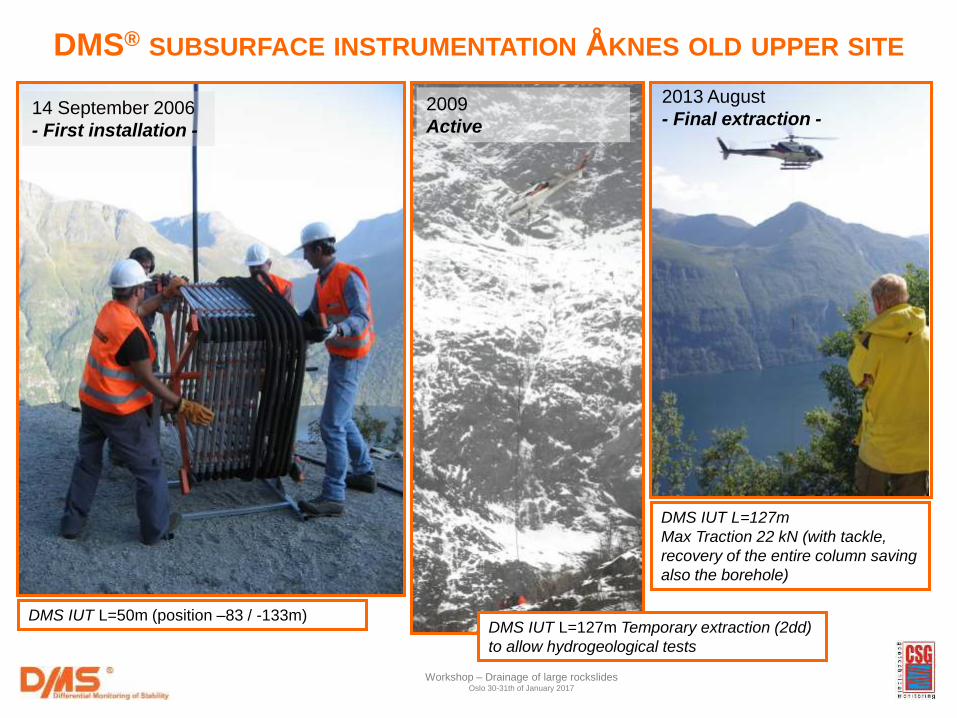
14 September 2006
- First installation -
DMS® SUBSURFACE INSTRUMENTATION ÅKNES OLD UPPER SITE
DMS IUT L=127m Temporary extraction (2dd)
to allow hydrogeological tests
2009
Active
2013 August
- Final extraction -
Workshop – Drainage of large rockslides Oslo 30-31th of January 2017
DMS IUT L=50m (position –83 / -133m)
DMS IUT L=127m
Max Traction 22 kN (with tackle,
recovery of the entire column saving
also the borehole)
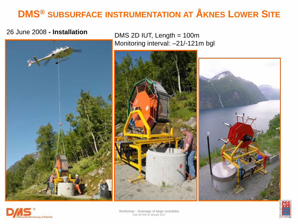
26 June 2008 - Installation DMS 2D IUT, Length = 100m
Monitoring interval: –21/-121m bgl
Workshop – Drainage of large rockslides Oslo 30-31th of January 2017
DMS® SUBSURFACE INSTRUMENTATION AT ÅKNES LOWER SITE
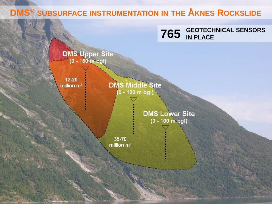
GEOTECHNICAL SENSORS
IN PLACE
DMS® SUBSURFACE INSTRUMENTATION IN THE ÅKNES ROCKSLIDE
765
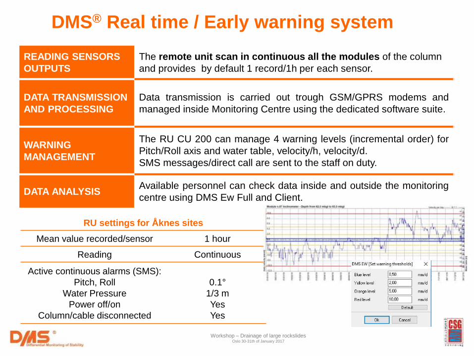
RU settings for Åknes sites
Mean value recorded/sensor 1 hour
Reading Continuous
Active continuous alarms (SMS):
Pitch, Roll
Water Pressure
Power off/on
Column/cable disconnected
0.1°
1/3 m
Yes
Yes
CU Settings in Aknes sites
DMS® Real time / Early warning system
Workshop – Drainage of large rockslides Oslo 30-31th of January 2017
READING SENSORS
OUTPUTS
The remote unit scan in continuous all the modules of the column
and provides by default 1 record/1h per each sensor.
DATA TRANSMISSION
AND PROCESSING
Data transmission is carried out trough GSM/GPRS modems and
managed inside Monitoring Centre using the dedicated software suite.
WARNING
MANAGEMENT
The RU CU 200 can manage 4 warning levels (incremental order) for
Pitch/Roll axis and water table, velocity/h, velocity/d.
SMS messages/direct call are sent to the staff on duty.
DATA ANALYSIS Available personnel can check data inside and outside the monitoring
centre using DMS Ew Full and Client.
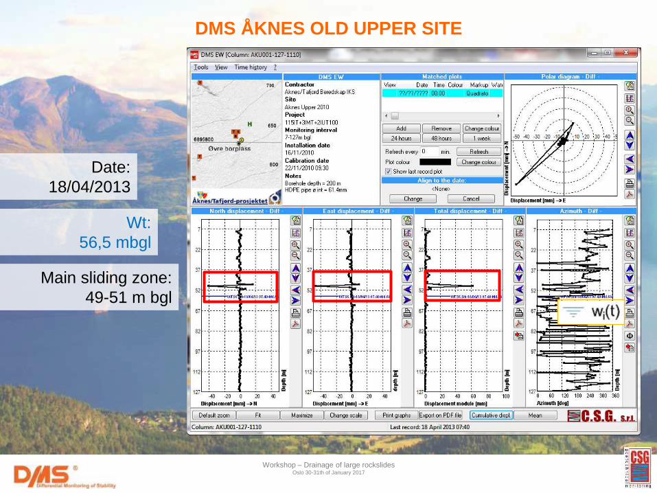
DMS ÅKNES OLD UPPER SITE
Workshop – Drainage of large rockslides Oslo 30-31th of January 2017
Date:
18/04/2013
Wt:
56,5 mbgl
Main sliding zone:
49-51 m bgl
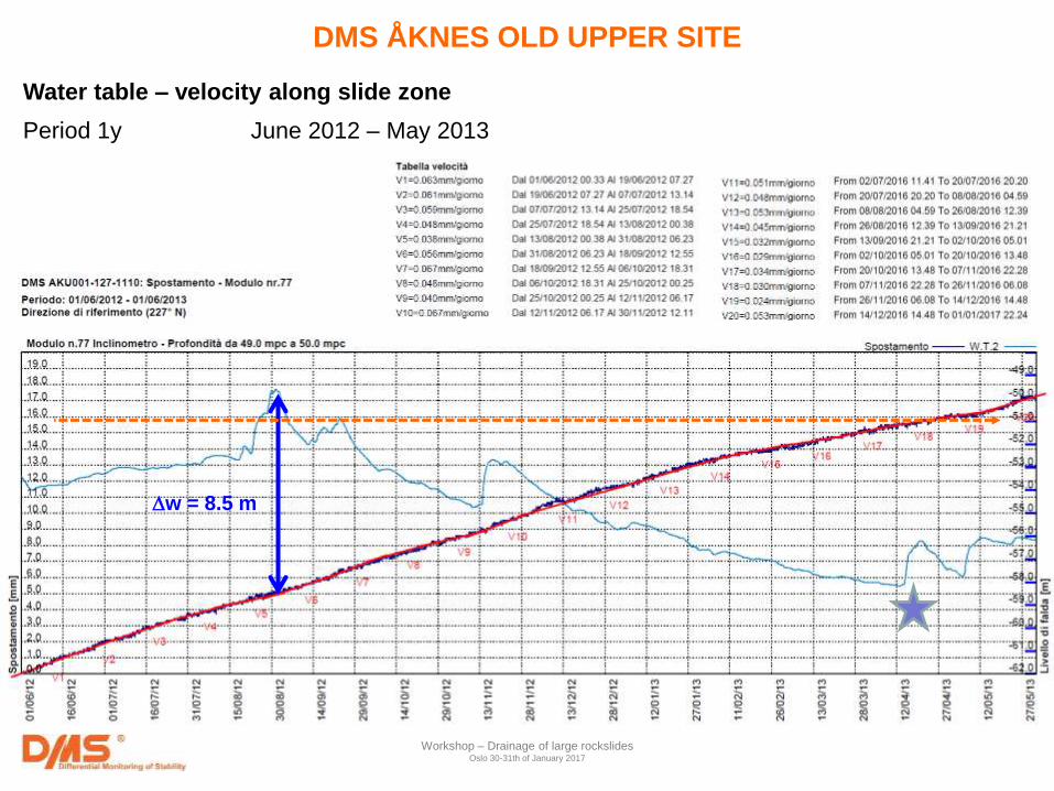
Water table – velocity along slide zone
Period 1y June 2012 – May 2013
DMS ÅKNES OLD UPPER SITE
w = 8.5 m
Workshop – Drainage of large rockslides Oslo 30-31th of January 2017
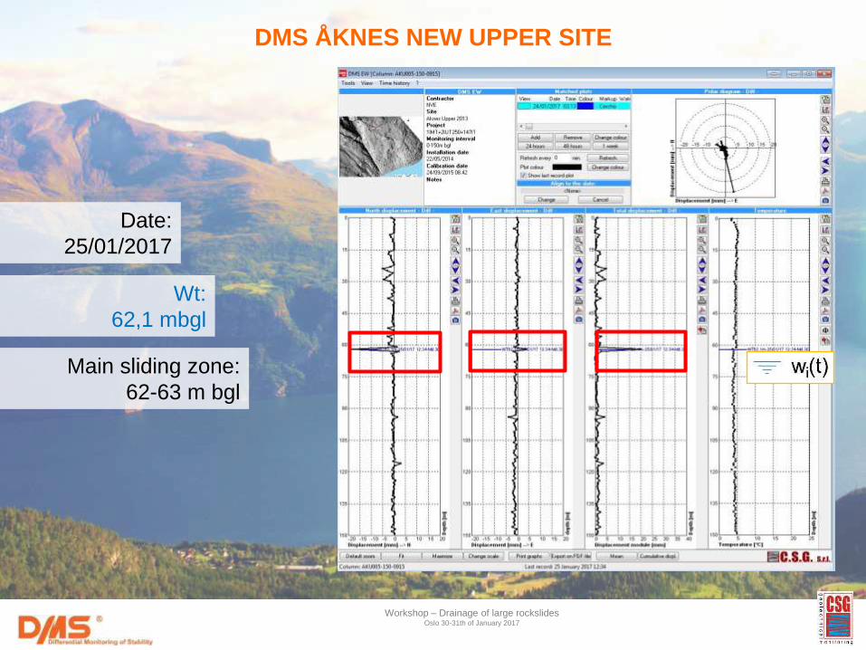
DMS ÅKNES NEW UPPER SITE
Workshop – Drainage of large rockslides Oslo 30-31th of January 2017
Date:
25/01/2017
Wt:
62,1 mbgl
Main sliding zone:
62-63 m bgl
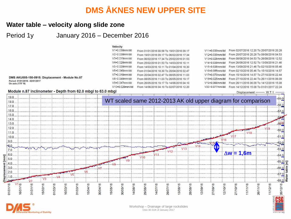
Water table – velocity along slide zone
Period 1y January 2016 – December 2016
w = 1,6m
Workshop – Drainage of large rockslides Oslo 30-31th of January 2017
DMS ÅKNES NEW UPPER SITE
WT scaled same 2012-2013 AK old upper diagram for comparison
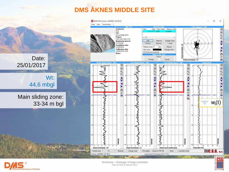
DMS ÅKNES MIDDLE SITE
Workshop – Drainage of large rockslides Oslo 30-31th of January 2017
Date:
25/01/2017
Wt:
44,6 mbgl
Main sliding zone:
33-34 m bgl
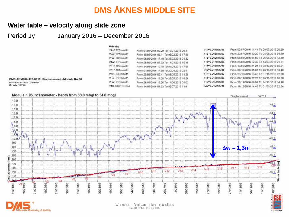
Water table – velocity along slide zone
Period 1y January 2016 – December 2016
w = 1,3m
Workshop – Drainage of large rockslides Oslo 30-31th of January 2017
DMS ÅKNES MIDDLE SITE
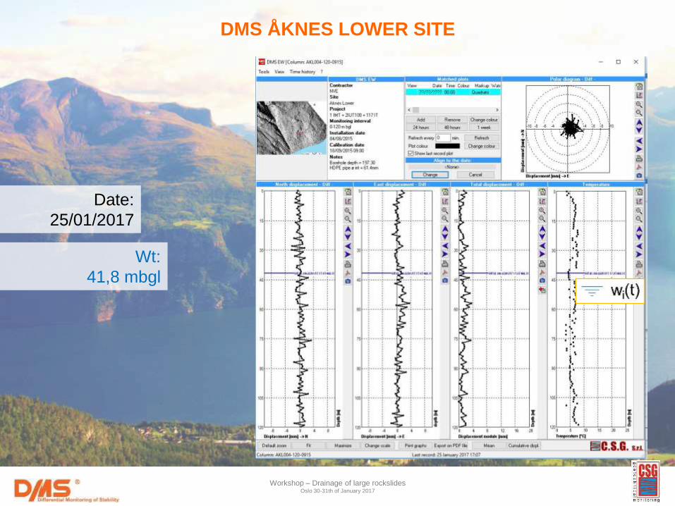
DMS ÅKNES LOWER SITE
Workshop – Drainage of large rockslides Oslo 30-31th of January 2017
Date:
25/01/2017
Wt:
41,8 mbgl
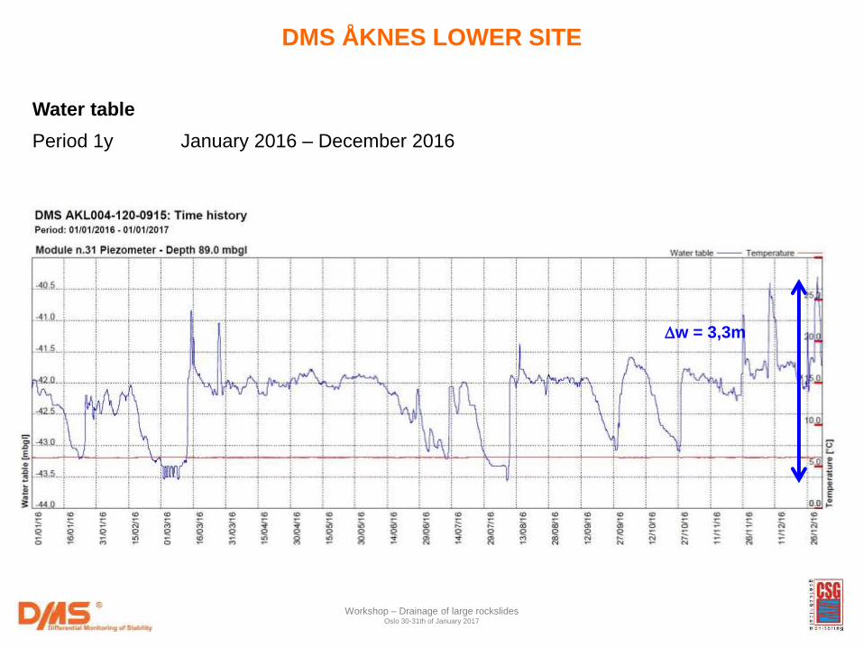
Water table
Period 1y January 2016 – December 2016
w = 3,3m
Workshop – Drainage of large rockslides Oslo 30-31th of January 2017
DMS ÅKNES LOWER SITE
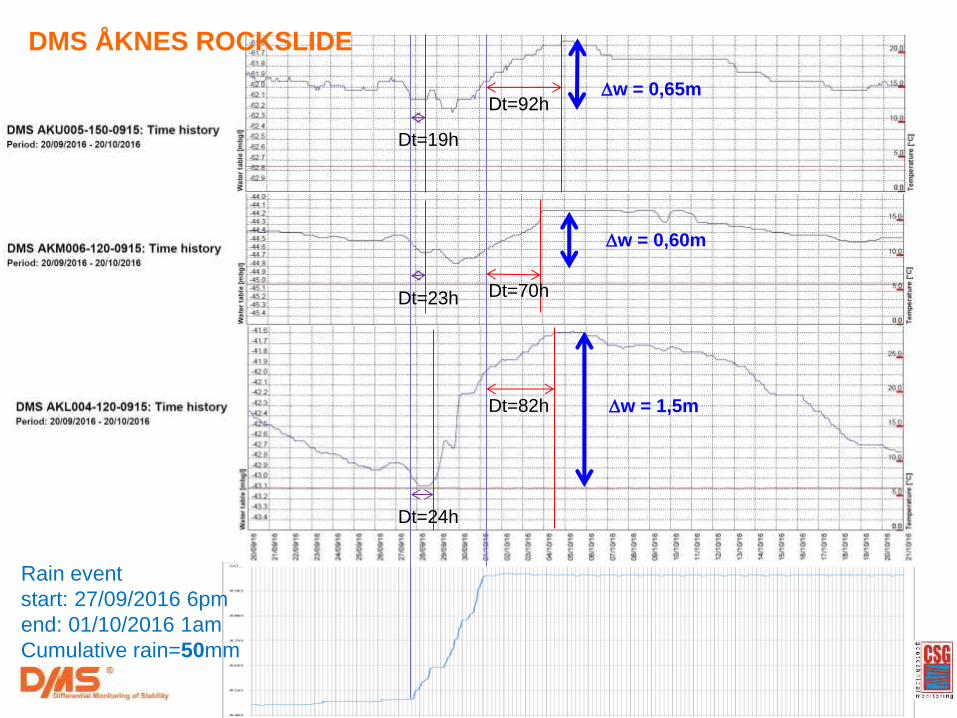
Rain event
start: 27/09/2016 6pm
end: 01/10/2016 1am
Cumulative rain=50mm
Dt=19h
Dt=82h
Dt=23h
Dt=24h
Dt=70h
Dt=92h
w = 1,5m
w = 0,60m
w = 0,65m
DMS ÅKNES ROCKSLIDE
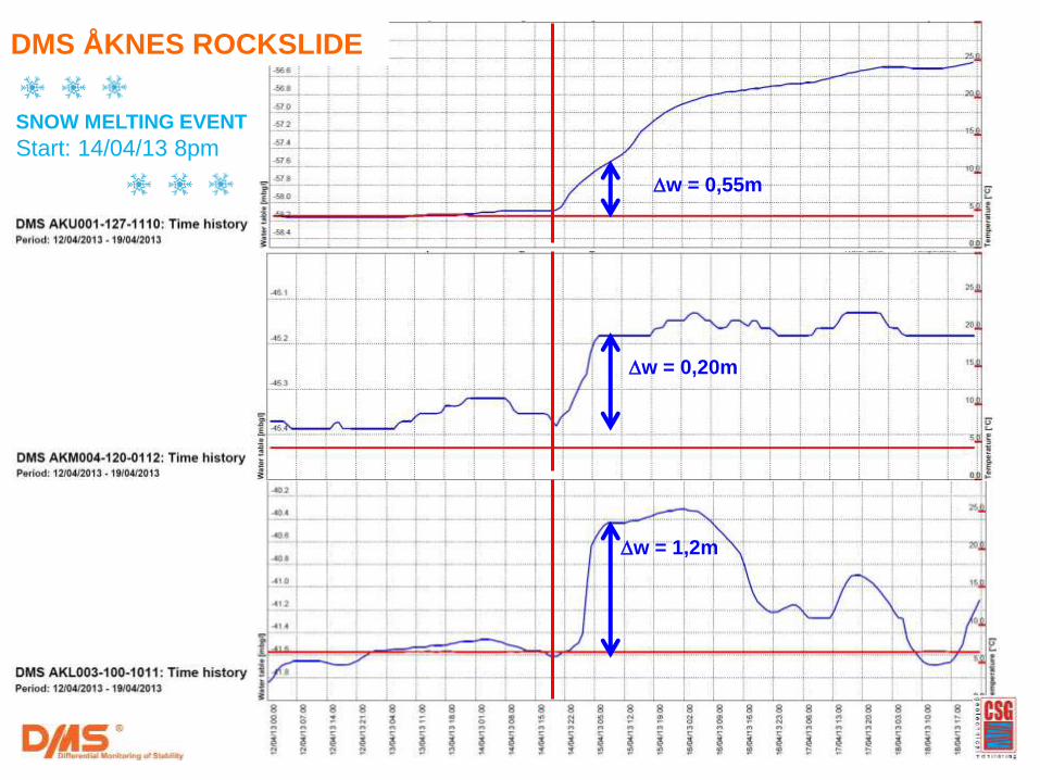
SNOW MELTING EVENT
Start: 14/04/13 8pm
w = 1,2m
w = 0,20m
w = 0,55m
DMS ÅKNES ROCKSLIDE
SNOW MELTING EVENT
Start: 14/04/13 8pm
w = 0,55m
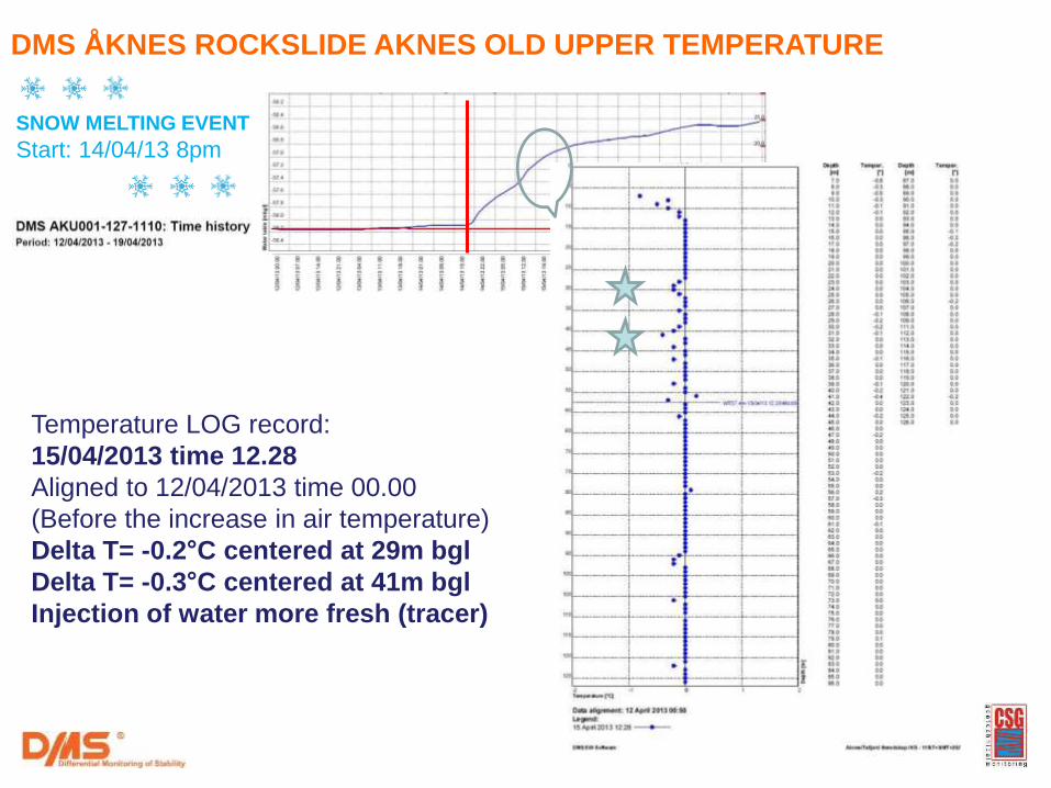
DMS ÅKNES ROCKSLIDE AKNES OLD UPPER TEMPERATURE
Temperature LOG record:
15/04/2013 time 12.28
Aligned to 12/04/2013 time 00.00
(Before the increase in air temperature)
Delta T= -0.2°C centered at 29m bgl
Delta T= -0.3°C centered at 41m bgl
Injection of water more fresh (tracer)
Workshop – Drainage of large rockslides Oslo 30-31th of January 2017
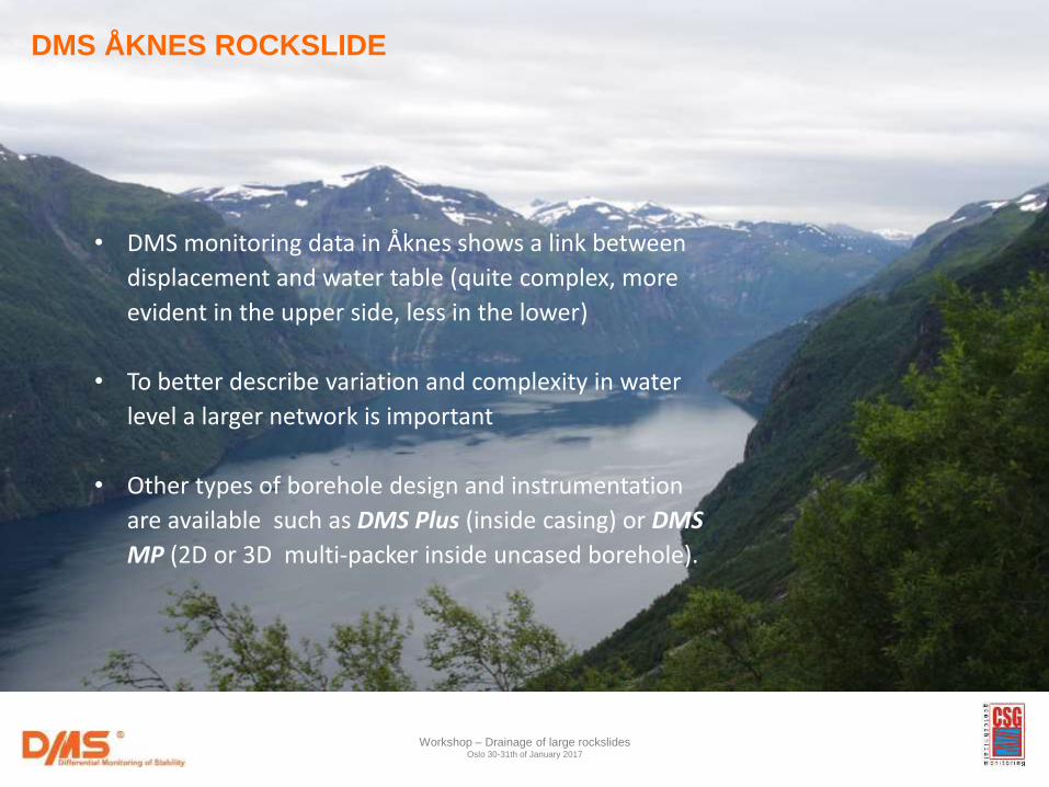
• DMS monitoring data in Åknes shows a link between
displacement and water table (quite complex, more
evident in the upper side, less in the lower)
• To better describe variation and complexity in water
level a larger network is important
• Other types of borehole design and instrumentation
are available such as DMS Plus (inside casing) or DMS
MP (2D or 3D multi-packer inside uncased borehole).
DMS ÅKNES ROCKSLIDE
INTERNATIONAL GEOTECHNICAL AND STRUCTURAL MONITORING
COURSE 2016
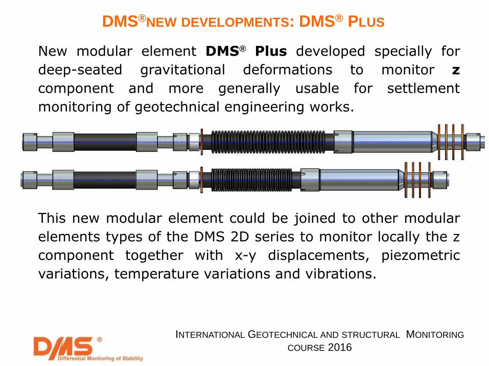
New modular element DMS® Plus developed specially for
deep-seated gravitational deformations to monitor z
component and more generally usable for settlement
monitoring of geotechnical engineering works.
This new modular element could be joined to other modular
elements types of the DMS 2D series to monitor locally the z
component together with x-y displacements, piezometric
variations, temperature variations and vibrations.
DMS®NEW DEVELOPMENTS: DMS® PLUS
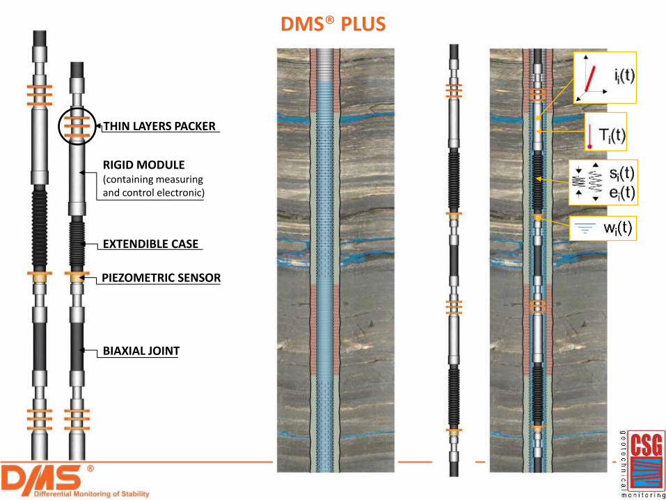
DMS® PLUS
RIGID MODULE (containing measuring and control electronic)
THIN LAYERS PACKER
EXTENDIBLE CASE
PIEZOMETRIC SENSOR
BIAXIAL JOINT
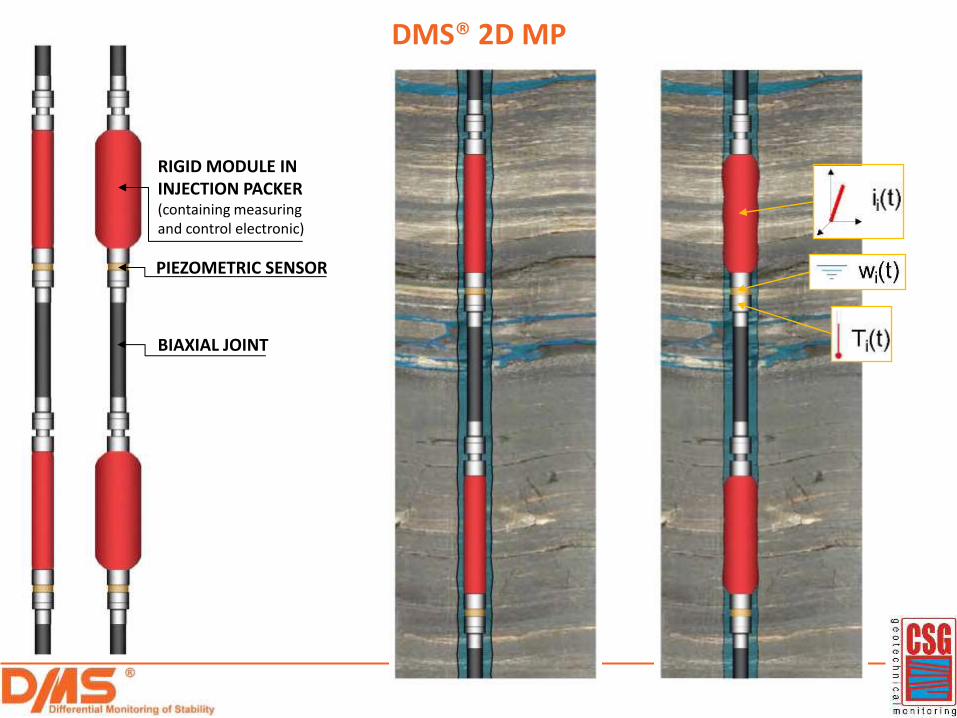
DMS® 2D MP
RIGID MODULE IN INJECTION PACKER (containing measuring and control electronic)
PIEZOMETRIC SENSOR
BIAXIAL JOINT
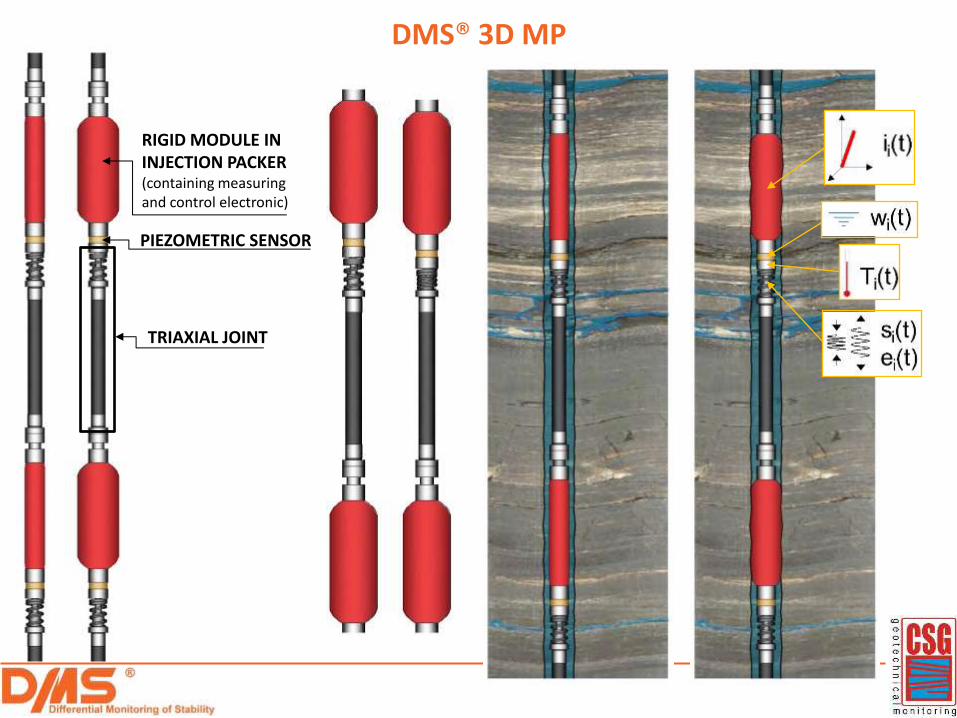
DMS® 3D MP
RIGID MODULE IN INJECTION PACKER (containing measuring and control electronic)
PIEZOMETRIC SENSOR
TRIAXIAL JOINT
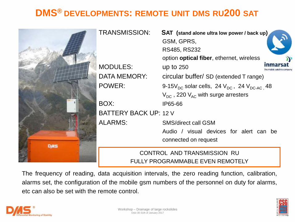
TRANSMISSION: SAT (stand alone ultra low power / back up)
GSM, GPRS,
RS485, RS232
option optical fiber, ethernet, wireless
MODULES: up to 250
DATA MEMORY: circular buffer/ SD (extended T range)
POWER: 9-15VDC solar cells, 24 VDC , 24 VDC-AC , 48
VDC , 220 VAC with surge arresters
BOX: IP65-66
BATTERY BACK UP: 12 V
ALARMS: SMS/direct call GSM
Audio / visual devices for alert can be
connected on request
CONTROL AND TRANSMISSION RU
FULLY PROGRAMMABLE EVEN REMOTELY
The frequency of reading, data acquisition intervals, the zero reading function, calibration,
alarms set, the configuration of the mobile gsm numbers of the personnel on duty for alarms,
etc can also be set with the remote control.
DMS® DEVELOPMENTS: REMOTE UNIT DMS RU200 SAT
Workshop – Drainage of large rockslides Oslo 30-31th of January 2017
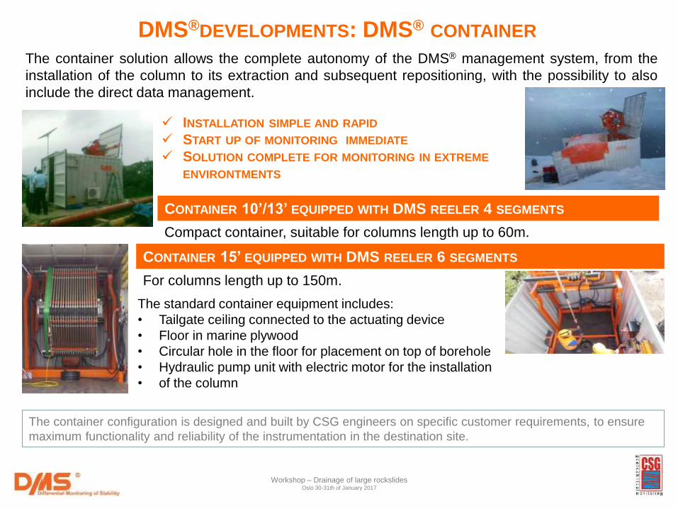
CONTAINER 10’/13’ EQUIPPED WITH DMS REELER 4 SEGMENTS
The standard container equipment includes:
• Tailgate ceiling connected to the actuating device
• Floor in marine plywood
• Circular hole in the floor for placement on top of borehole
• Hydraulic pump unit with electric motor for the installation
• of the column
The container solution allows the complete autonomy of the DMS® management system, from the
installation of the column to its extraction and subsequent repositioning, with the possibility to also
include the direct data management.
CONTAINER 15’ EQUIPPED WITH DMS REELER 6 SEGMENTS
INSTALLATION SIMPLE AND RAPID
START UP OF MONITORING IMMEDIATE
SOLUTION COMPLETE FOR MONITORING IN EXTREME
ENVIRONTMENTS
The container configuration is designed and built by CSG engineers on specific customer requirements, to ensure
maximum functionality and reliability of the instrumentation in the destination site.
Compact container, suitable for columns length up to 60m.
For columns length up to 150m.
DMS®DEVELOPMENTS: DMS® CONTAINER
Workshop – Drainage of large rockslides Oslo 30-31th of January 2017
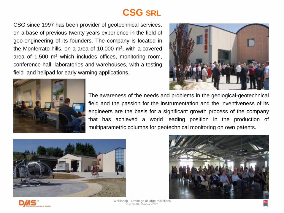
CSG since 1997 has been provider of geotechnical services,
on a base of previous twenty years experience in the field of
geo-engineering of its founders. The company is located in
the Monferrato hills, on a area of 10.000 m2, with a covered
area of 1.500 m2 which includes offices, monitoring room,
conference hall, laboratories and warehouses, with a testing
field and helipad for early warning applications.
The awareness of the needs and problems in the geological-geotechnical
field and the passion for the instrumentation and the inventiveness of its
engineers are the basis for a significant growth process of the company
that has achieved a world leading position in the production of
multiparametric columns for geotechnical monitoring on own patents.
CSG SRL
Workshop – Drainage of large rockslides Oslo 30-31th of January 2017
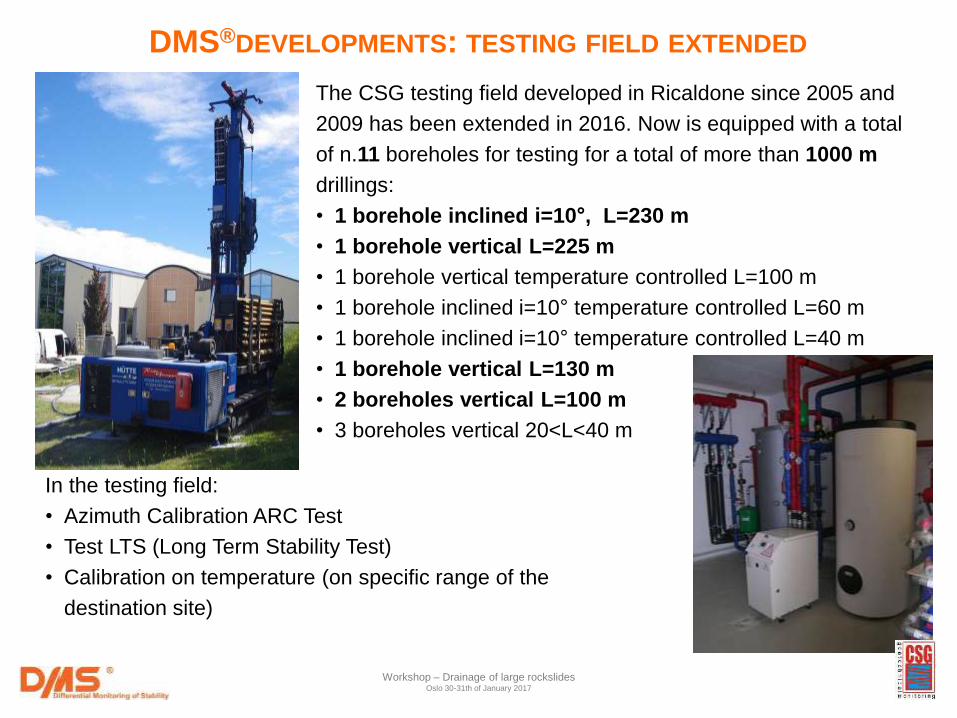
The CSG testing field developed in Ricaldone since 2005 and
2009 has been extended in 2016. Now is equipped with a total
of n.11 boreholes for testing for a total of more than 1000 m
drillings:
• 1 borehole inclined i=10°, L=230 m
• 1 borehole vertical L=225 m
• 1 borehole vertical temperature controlled L=100 m
• 1 borehole inclined i=10° temperature controlled L=60 m
• 1 borehole inclined i=10° temperature controlled L=40 m
• 1 borehole vertical L=130 m
• 2 boreholes vertical L=100 m
• 3 boreholes vertical 20<L<40 m
In the testing field:
• Azimuth Calibration ARC Test
• Test LTS (Long Term Stability Test)
• Calibration on temperature (on specific range of the
destination site)
DMS®DEVELOPMENTS: TESTING FIELD EXTENDED
Workshop – Drainage of large rockslides Oslo 30-31th of January 2017
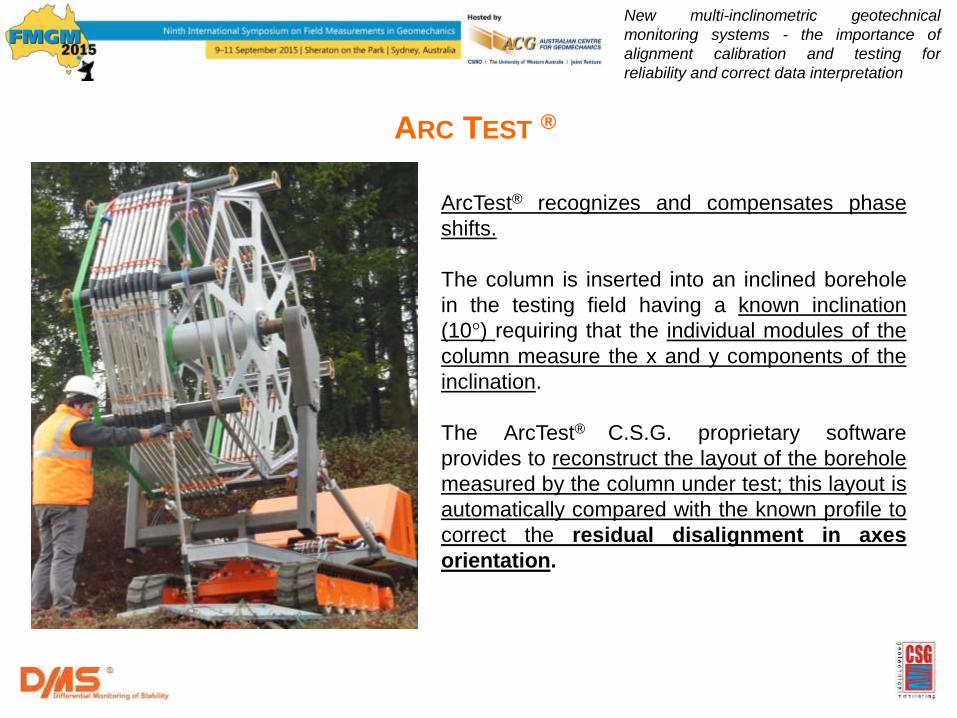
ARC TEST ®
ArcTest® recognizes and compensates phase
shifts.
The column is inserted into an inclined borehole
in the testing field having a known inclination
(10°) requiring that the individual modules of the
column measure the x and y components of the
inclination.
The ArcTest® C.S.G. proprietary software
provides to reconstruct the layout of the borehole
measured by the column under test; this layout is
automatically compared with the known profile to
correct the residual disalignment in axes
orientation.
New multi-inclinometric geotechnical
monitoring systems - the importance of
alignment calibration and testing for
reliability and correct data interpretation
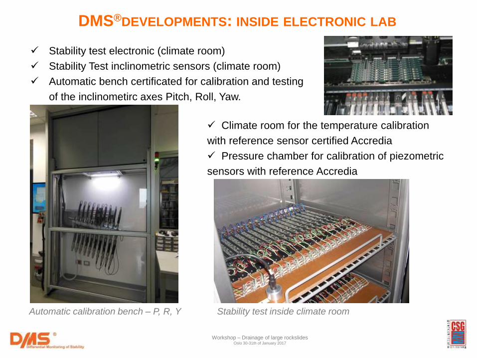
Stability test electronic (climate room)
Stability Test inclinometric sensors (climate room)
Automatic bench certificated for calibration and testing
of the inclinometirc axes Pitch, Roll, Yaw.
Climate room for the temperature calibration
with reference sensor certified Accredia
Pressure chamber for calibration of piezometric
sensors with reference Accredia
Stability test inside climate room
DMS®DEVELOPMENTS: INSIDE ELECTRONIC LAB
Automatic calibration bench – P, R, Y
Workshop – Drainage of large rockslides Oslo 30-31th of January 2017
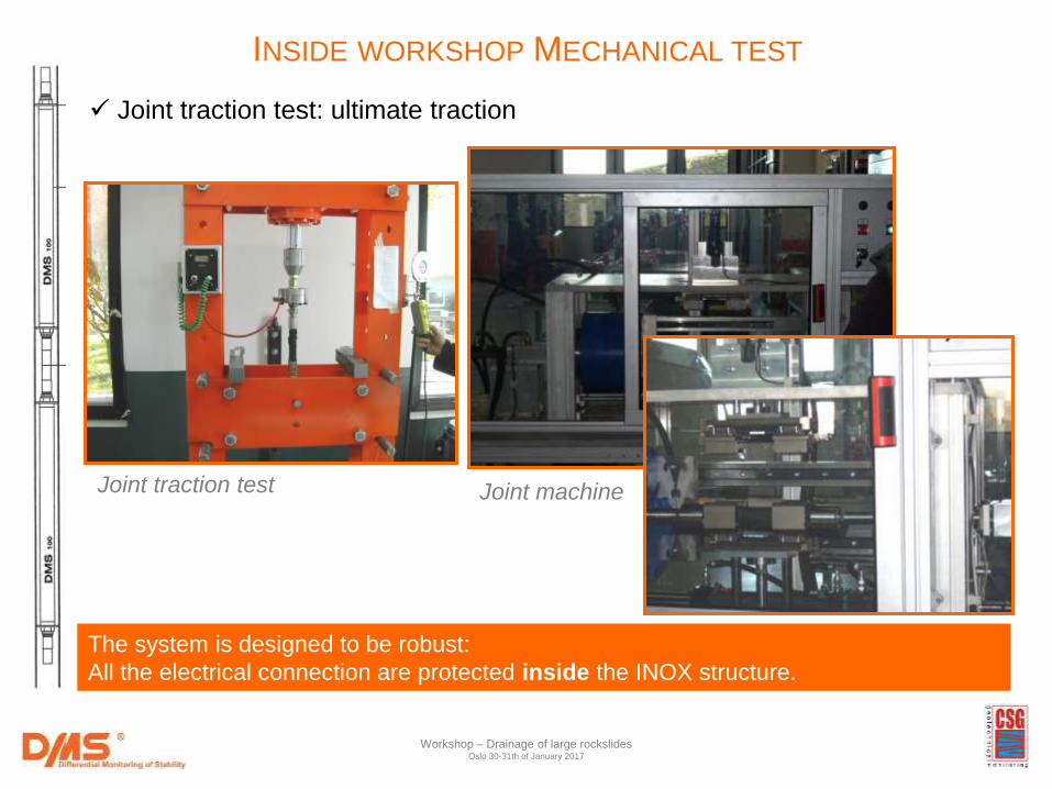
Joint traction test
The system is designed to be robust:
All the electrical connection are protected inside the INOX structure.
Joint traction test: ultimate traction
Joint machine
INSIDE WORKSHOP MECHANICAL TEST
Workshop – Drainage of large rockslides Oslo 30-31th of January 2017
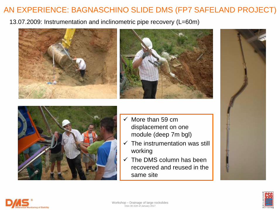
More than 59 cm
displacement on one
module (deep 7m bgl)
The instrumentation was still
working
The DMS column has been
recovered and reused in the
same site
13.07.2009: Instrumentation and inclinometric pipe recovery (L=60m)
AN EXPERIENCE: BAGNASCHINO SLIDE DMS (FP7 SAFELAND PROJECT)
Workshop – Drainage of large rockslides Oslo 30-31th of January 2017
Workshop – Drainage of large rockslides Oslo 30-31th of January 2017
The geotechnical continuous monitoring through new
multi-parametric techniques can provide a valuable
contribution in the resolution of stability problems,
supporting not only monitoring and early warning but
also the design, construction and testing of mitigation
actions by providing reliable parameters and
guidance to the project engineers.
THANKS FOR YOUR ATTENTION!