Expanded Communications Satellite Surveillance and ... · Expanded Communications Satellite...
76
The Nautilus Institute for Security and Sustainability Expanded Communications Satellite Surveillance and Intelligence Activities utilising Multi-beam Antenna Systems Desmond Ball, Duncan Campbell, Bill Robinson and Richard Tanter Nautilus Institute for Security and Sustainability Special Report 28 May 2015
Transcript of Expanded Communications Satellite Surveillance and ... · Expanded Communications Satellite...
The Nautilus Institute for Security and Sustainability
Expanded Communications Satellite
Surveillance and Intelligence Activities
utilising Multi-beam Antenna Systems
Desmond Ball, Duncan Campbell, Bill Robinson and Richard Tanter
Nautilus Institute for Security and Sustainability Special Report 28 May 2015
1
Summary The recent expansion of FORNSAT/COMSAT (foreign satellite/communications satellite) interception by the UKUSA or Five Eyes (FVEY) partners has involved the installation over the past eight years of multiple advanced quasi-parabolic multi-beam antennas, known as Torus, each of which can intercept up to 35 satellite communications beams. Material released by Edward Snowden identifies a ‘New Collection Posture’, known as ‘Collect-it-all’, an increasingly comprehensive approach to SIGINT collection from communications satellites by the NSA and its partners. There are about 232 antennas available at identified current Five Eyes FORNSAT/COMSAT sites, about 100 more antennas than in 2000. We conclude that development work at the observed Five Eyes FORNSAT/ COMSAT sites since 2000 has more than doubled coverage, and that adding Torus has more than trebled potential coverage of global commercial satellites. The report also discusses Torus antennas operating in Russia and Ukraine, and other U.S. Torus antennas.
Authors Desmond Ball is Emeritus Professor at the Australian National University (ANU). He was a Special Professor at the ANU's Strategic and Defence Studies Centre from 1987 to 2013, and he served as Head of the Centre from 1984 to 1991. Duncan Campbell is an investigative journalist, author, consultant, and television producer; forensic expert witness on computers and communications data; the author of Interception Capabilities 2000, a report on the ECHELON satellite surveillance system for the European Parliament, Visiting Fellow, Media School, Bournemouth University (2002-). Formerly: Staff Writer, New Statesman: Co-Founder, Stonewall; Co-Founder (1991), Investigation and Production Television: Founder Member, International Consortium of Investigative Journalists. Bill Robinson writes the blog Lux Ex Umbra, which focuses on Canadian signals intelligence activities. He has been an active student of signals intelligence matters since the mid-1980s, and from 1986 to 2001 was on the staff of the Canadian peace research organization Project Ploughshares. Richard Tanter is Senior Research Associate at the Nautilus Institute and Honorary Professor in the School of Political and Social Sciences at the University of Melbourne. Recommended Citation: Desmond Ball, Duncan Campbell, Bill Robinson and Richard Tanter, “Expanded Communications Satellite Surveillance and Intelligence Activities utilising Multi-beam Antenna Systems,” NAPSNet Special Report, 28 May 2015.
2
http://nautilus.org/napsnet/napsnet-special-reports/expanded-communications-satellite-surveillance-and-intelligence-activities-utilising-multi-beam-antenna-systems The views expressed in this report do not necessarily reflect the official policy or position of the Nautilus Institute. Readers should note that Nautilus seeks a diversity of views and opinions on significant topics in order to identify common ground.
3
Summary ............................................................................................................................................... 1 Authors ................................................................................................................................................... 1 Glossary.................................................................................................................................................. 4 1. Introduction ..................................................................................................................................... 6 2. Five Eyes FORNSAT/COMSAT interception sites .......................................................... 12
2.1 GCHQ Bude, Cornwall ........................................................................................................ 17 2.2 Menwith Hill Station, Harrogate, Yorkshire ............................................................. 20 2.3 Ayios Nikolaos, Cyprus ..................................................................................................... 25 2.4 Seeb, Oman [LECKWITH] ................................................................................................. 28 2.5 Pine Gap, Northern Territory, Australia ..................................................................... 29 2.6 Waihopai, New Zealand .................................................................................................... 32
3. Technical and historical aspects of multi-beam systems ............................................ 38
3.1 Technical aspects ................................................................................................................ 38 3.2 Historical development for orthodox satellite reception .................................... 42
4. Russian and Ukrainian multi-beam communications interception antennas .... 44
4.1 Russian multi-beam system, Klimovsk ....................................................................... 44 4.2 Ukrainian multi-beam system, Ovidiopol-2, Dobroaleksandrovka ................. 48
5. Non-SIGINT U.S. military multi-beam antennas ............................................................. 53
5.1 March Air Force Base, Riverside, California ............................................................. 53 5.2 NSA HQ, Fort Meade, Maryland ..................................................................................... 54 5.3 CIA HQ, Langley, Virginia ................................................................................................. 57 5.4 Fort Belvoir, Virginia ......................................................................................................... 57 5.5 Naval Information Operations Command (NIOC), Suitland, Maryland .......... 58 5.6 Schriever Air Force Base, Colorado .............................................................................. 58 5.7 U.S. Army Transmitter Facility, Egelsbach, Germany ............................................ 59 5.8 Torii Station Teleport, Okinawa .................................................................................... 61 5.9 NASA Langley Research Center, Virginia ................................................................... 61 5.10 ATCi Warrior Satellite Surveillance System ........................................................... 63
Annexe 1: Analysis of satellite terminals at Five Eyes FORNSAT/COMSAT sites,
2000–2015 ..................................................................................................................................... 66 References .......................................................................................................................................... 70
4
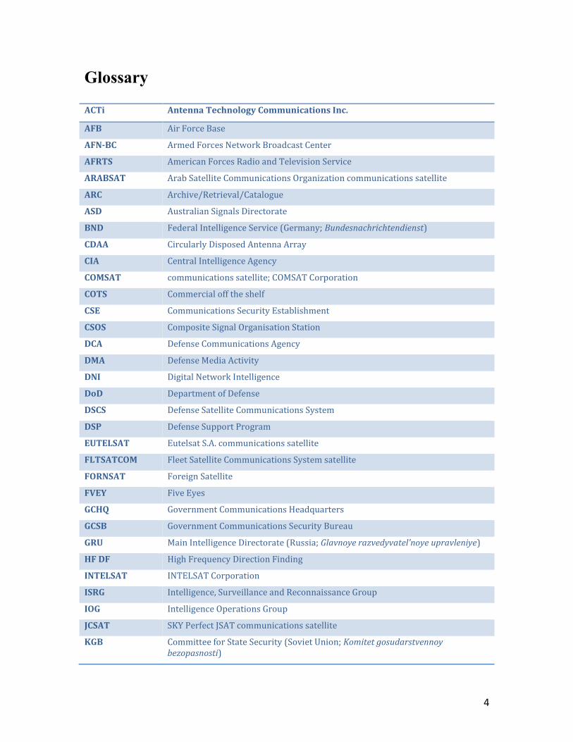
Glossary ACTi Antenna Technology Communications Inc.
AFB Air Force Base
AFN-BC Armed Forces Network Broadcast Center
AFRTS American Forces Radio and Television Service
ARABSAT Arab Satellite Communications Organization communications satellite
ARC Archive/Retrieval/Catalogue
ASD Australian Signals Directorate
BND Federal Intelligence Service (Germany; Bundesnachrichtendienst)
CDAA Circularly Disposed Antenna Array
CIA Central Intelligence Agency
COMSAT communications satellite; COMSAT Corporation
COTS Commercial off the shelf
CSE Communications Security Establishment
CSOS Composite Signal Organisation Station
DCA Defense Communications Agency
DMA Defense Media Activity
DNI Digital Network Intelligence
DoD Department of Defense
DSCS Defense Satellite Communications System
DSP Defense Support Program
EUTELSAT Eutelsat S.A. communications satellite
FLTSATCOM Fleet Satellite Communications System satellite
FORNSAT Foreign Satellite
FVEY Five Eyes
GCHQ Government Communications Headquarters
GCSB Government Communications Security Bureau
GRU Main Intelligence Directorate (Russia; Glavnoye razvedyvatel'noye upravleniye)
HF DF High Frequency Direction Finding
INTELSAT INTELSAT Corporation
ISRG Intelligence, Surveillance and Reconnaissance Group
IOG Intelligence Operations Group
JCSAT SKY Perfect JSAT communications satellite
KGB Committee for State Security (Soviet Union; Komitet gosudarstvennoy bezopasnosti)

5
LES Lincoln Experimental Satellite
LNB Low Noise Block
MBTA Multi-beam Torus Antenna
MHS Menwith Hill Station
MVR Massive Volume Reduction
NASA National Aeronautics and Space Administration
NIOC Naval Information Operations Command
NRO National Reconnaissance Office
NSA National Security Agency
OSD-PA Office of the Secretary of Defense for Public Affairs
RF Radio Frequency
RGS Relay Ground Station
RSI Radiation Systems Inc
SATCOM Satellite Communications
SBIRS Space-Based Infrared System
SBU Security Service of Ukraine (Sluzhba Bezpeky Ukrayiny)
SCA Service Cryptological Agency
SCE Special Collection Elements
SI Special Intelligence
SIGAD SIGINT Activity Designator
SIGINT Signals Intelligence
SZRU Foreign Intelligence Service of Ukraine (Sluzhba zovnishn’oyi rozvidky Ukrayiny)
UKUSA UKUSA Agreement(s); see Endnote 2.
XKS XKeyscore
6
1. Introduction The recent expansion of FORNSAT/COMSAT1 (foreign satellite/
communications satellite) interception by the UKUSA (Five Eyes or FVEY) partners
– the U.S. National Security Agency (NSA), the British Government Communications
Headquarters (GCHQ), Canada’s Communications Security Establishment (CSE), the
Australian Signals Directorate (ASD), and New Zealand’s Government
Communications Security Bureau (GCSB) – has involved the installation over the
past eight years of multiple advanced quasi-parabolic multi-beam antennas, known
as Torus, which can simultaneously intercept up to 35 satellite communications
beams from single antenna installations.2 This report identifies sites now
performing Torus FORNSAT/COMSAT collection activity and some of their
operational parameters.
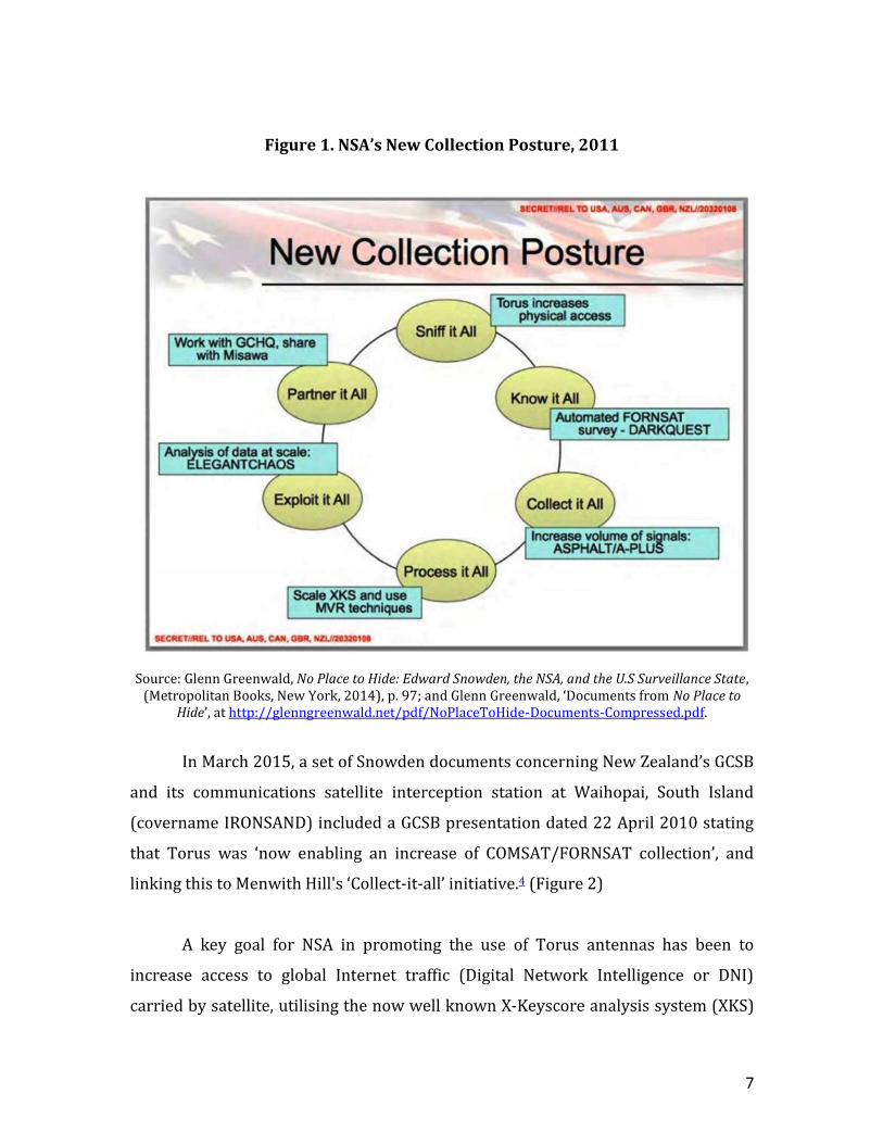
Public awareness of the Torus program is largely a product of revelations by
former NSA contractor Edward Snowden. The first published reference to the use of
Torus technology for SIGINT appears in a slide published in a book by Glenn
Greenwald in May 2014. A Top Secret SI Powerpoint presentation to the 2011 Five
Eyes Annual Conference outlined a ‘New Collection Posture’, known as ‘Collect-it-all’
then being pioneered at NSA's Menwith Hill Station (MHS) in Britain as Project
ASPHALT. The slides describe a new and increasingly comprehensive approach to
SIGINT collection from communications satellites (COMSATs) and state that ‘Torus
increases physical access’, enabling the MHS station team to ‘sniff it all’ before
collecting and processing everything of interest.3 (Figure 1)
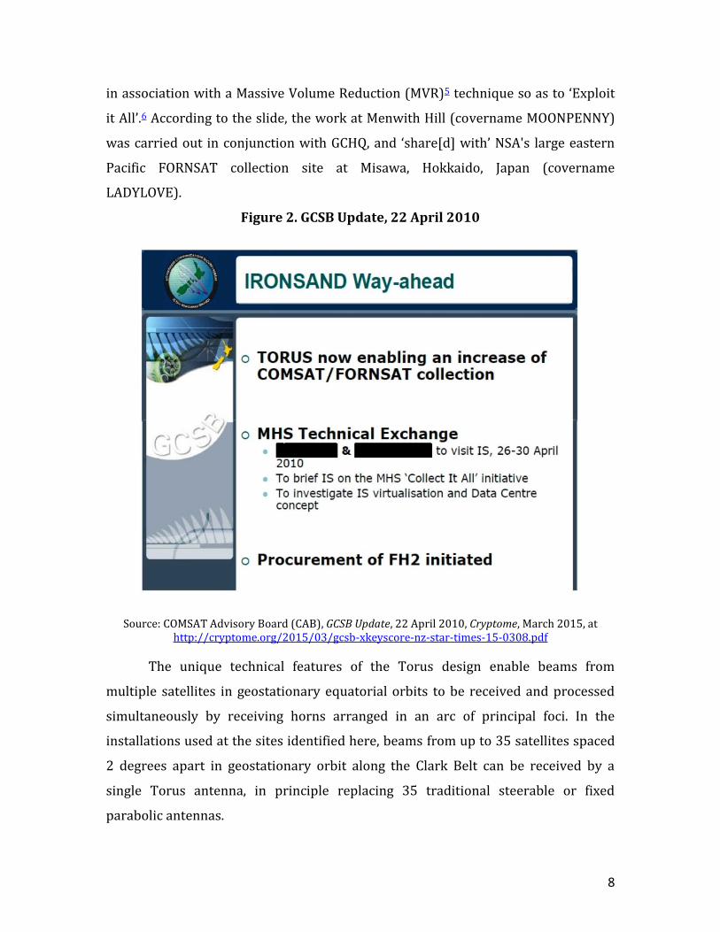
In March 2015, a set of Snowden documents concerning New Zealand’s GCSB
and its communications satellite interception station at Waihopai, South Island
(covername IRONSAND) included a GCSB presentation dated 22 April 2010 stating
that Torus was ‘now enabling an increase of COMSAT/FORNSAT collection’, and
linking this to Menwith Hill's ‘Collect-it-all’ initiative.4 (Figure 2)
7
Figure 1. NSA’s New Collection Posture, 2011
Source: Glenn Greenwald, No Place to Hide: Edward Snowden, the NSA, and the U.S Surveillance State, (Metropolitan Books, New York, 2014), p. 97; and Glenn Greenwald, ‘Documents from No Place to
Hide’, at http://glenngreenwald.net/pdf/NoPlaceToHide-Documents-Compressed.pdf.
In March 2015, a set of Snowden documents concerning New Zealand’s GCSB
and its communications satellite interception station at Waihopai, South Island
(covername IRONSAND) included a GCSB presentation dated 22 April 2010 stating
that Torus was ‘now enabling an increase of COMSAT/FORNSAT collection’, and
linking this to Menwith Hill's ‘Collect-it-all’ initiative.4 (Figure 2)
A key goal for NSA in promoting the use of Torus antennas has been to
increase access to global Internet traffic (Digital Network Intelligence or DNI)
carried by satellite, utilising the now well known X-Keyscore analysis system (XKS)
8
in association with a Massive Volume Reduction (MVR)5 technique so as to ‘Exploit
it All’.6 According to the slide, the work at Menwith Hill (covername MOONPENNY)
was carried out in conjunction with GCHQ, and ‘share[d] with’ NSA's large eastern
Pacific FORNSAT collection site at Misawa, Hokkaido, Japan (covername
LADYLOVE).
Figure 2. GCSB Update, 22 April 2010
Source: COMSAT Advisory Board (CAB), GCSB Update, 22 April 2010, Cryptome, March 2015, at http://cryptome.org/2015/03/gcsb-xkeyscore-nz-star-times-15-0308.pdf
The unique technical features of the Torus design enable beams from
multiple satellites in geostationary equatorial orbits to be received and processed
simultaneously by receiving horns arranged in an arc of principal foci. In the
installations used at the sites identified here, beams from up to 35 satellites spaced
2 degrees apart in geostationary orbit along the Clark Belt can be received by a
single Torus antenna, in principle replacing 35 traditional steerable or fixed
parabolic antennas.
9
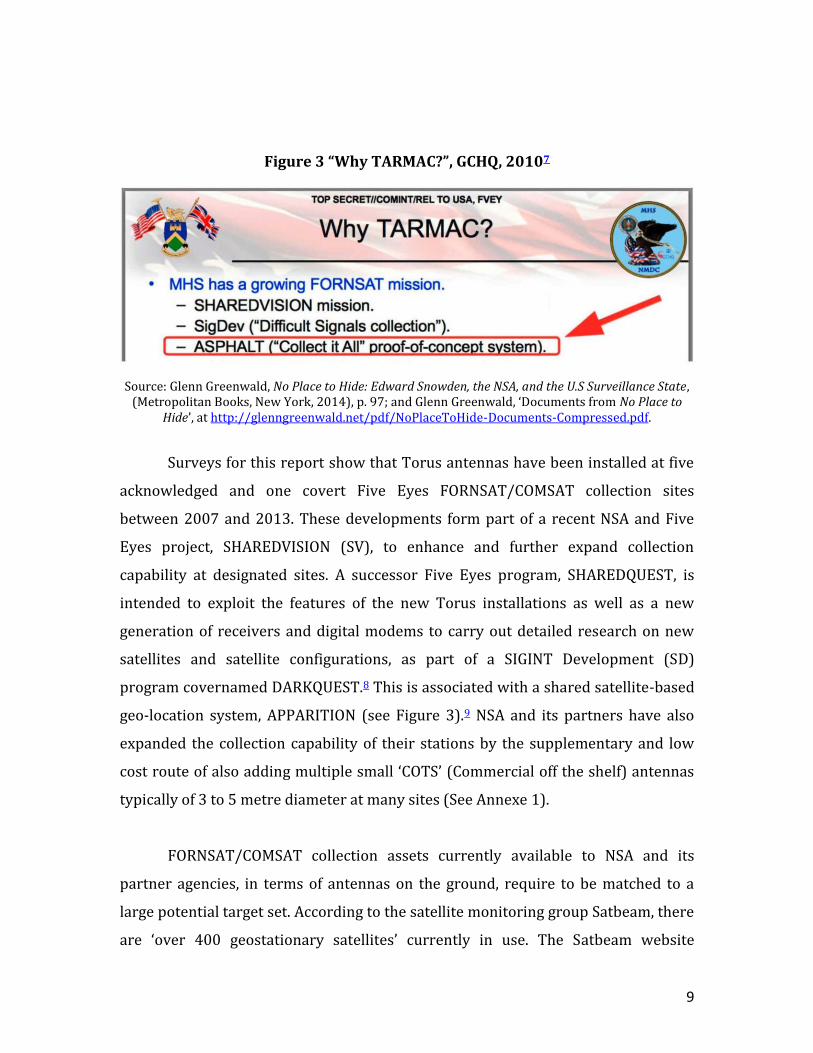
Figure 3 “Why TARMAC?”, GCHQ, 20107
Source: Glenn Greenwald, No Place to Hide: Edward Snowden, the NSA, and the U.S Surveillance State, (Metropolitan Books, New York, 2014), p. 97; and Glenn Greenwald, ‘Documents from No Place to
Hide’, at http://glenngreenwald.net/pdf/NoPlaceToHide-Documents-Compressed.pdf.
Surveys for this report show that Torus antennas have been installed at five
acknowledged and one covert Five Eyes FORNSAT/COMSAT collection sites
between 2007 and 2013. These developments form part of a recent NSA and Five
Eyes project, SHAREDVISION (SV), to enhance and further expand collection
capability at designated sites. A successor Five Eyes program, SHAREDQUEST, is
intended to exploit the features of the new Torus installations as well as a new
generation of receivers and digital modems to carry out detailed research on new
satellites and satellite configurations, as part of a SIGINT Development (SD)
program covernamed DARKQUEST.8 This is associated with a shared satellite-based
geo-location system, APPARITION (see Figure 3).9 NSA and its partners have also
expanded the collection capability of their stations by the supplementary and low
cost route of also adding multiple small ‘COTS’ (Commercial off the shelf) antennas
typically of 3 to 5 metre diameter at many sites (See Annexe 1).
FORNSAT/COMSAT collection assets currently available to NSA and its
partner agencies, in terms of antennas on the ground, require to be matched to a
large potential target set. According to the satellite monitoring group Satbeam, there
are ‘over 400 geostationary satellites’ currently in use. The Satbeam website
10
provides a detailed database identifying 272 communications satellites operating in
the Clark Belt, providing 9,890 downlink transponders (signal relays) or beams.10
Many of the downlinks are split into different regional patterns and into selected
spot beams so as to best use available satellite power.
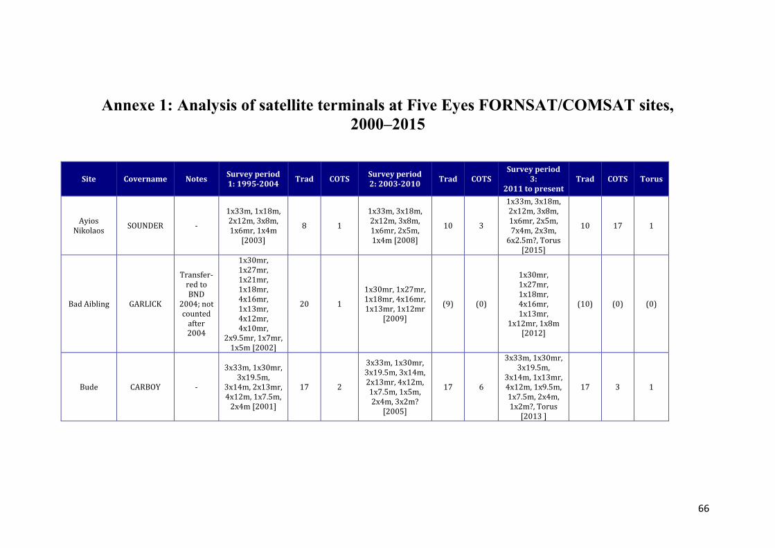
A survey using published historical imagery compiled for this report and
appearing in Annexe 1 suggests that there are currently about 232 antennas
available at identified current Five Eyes FORNSAT/COMSAT sites, including the new
Torus antennas, but excluding collocated antennas believed to be used for orthodox
satellite communications or for satellite ground control and processing.
Some antennas provide orthodox satellite communication for their host
site(s). At least one antenna on each FORNSAT/COMSAT site is typically allocated to
target (or SIGINT) development. This total is around 100 antennas larger than
measured in 2000 at the time of the ECHELON controversy11, and does not include
the multi-beam capability provided by Torus. The constellation of 6 Torus antennas
identified in this report have a maximum capacity of 210 additional beams in the
Ku- or C-bands.
We therefore conclude that development work at the observed FVEY
FORNSAT/COMSAT sites since 2000 has more than doubled coverage, and that
adding Torus has more than trebled potential coverage of global commercial
satellites.
Although these developments have taken place in open sight, the deployment
of the Torus antennas has mostly gone unheralded.12
To co-ordinate and prioritise the use of shared assets, NSA tasks priority
beams of interest to each Five Eyes FORNSAT site in accordance with a directed
survey plan drawn from a classified beam database similar to Satbeam,
GLOBALVIEW.13 The agencies operating the sites then assign antennas to collect and
11
then analyse and relay the beams required by NSA. In broad terms, a comparison of
satellites in orbit with ground assets suggests that only half of the available beams
for survey could have been collected until the advent of Torus systems and
additional COTS terminals; and that the Torus installations reported here, covering
a potential maximum of 210 targets, may have doubled Five Eyes' capacity to cover
the global satellite constellation.
Little information has been published concerning specific tasking and
sharing arrangements for satellite interception between Five Eyes partners and
Third Party nations. Germany is a significant exception. In 2004, the German foreign
intelligence agency BND took over NSA's large FORNSAT site at Bad Aibling, Bavaria
(former covername GARLICK), but continued to allow NSA remotely to task
‘selectors’ to the equipment operated at the site. In April 2014, a German
parliamentary enquiry determined that BND had improperly allowed NSA to use
tens of thousands of selectors to collect intelligence on the European Commission,
and other European government and commercial targets. Other reports quote
claims by BND staff that some improper and potentially unlawful targeting by NSA
had been detected and blocked.14
Surveys for this report of 11 previously reported Soviet COMSAT SIGINT
sites15 suggest that the former Soviet KGB installed Torus antennas for
simultaneous interception of multiple satellites in the geostationary arc at a much
earlier date, probably in the late 1980s. A massive multi-beam antenna is installed
at the Ovidiopol-2 SIGINT site, near Dobroaleksandrovka near Odessa in Ukraine,
and may have been in operation as early as 1987. A second multi-beam antenna was
installed at the same site in 2009-2010. The site is now operated by Ukraine’s
Foreign Intelligence Service (SZRU) (see Figures 31-34).
Russian military intelligence (GRU) installed a large multi-beam antenna
near Klimovsk, south of Moscow, in 2005-06 (see Figures 27-30). These
Soviet/Russian/Ukrainian multi-beam activities are briefly described in the fourth
12
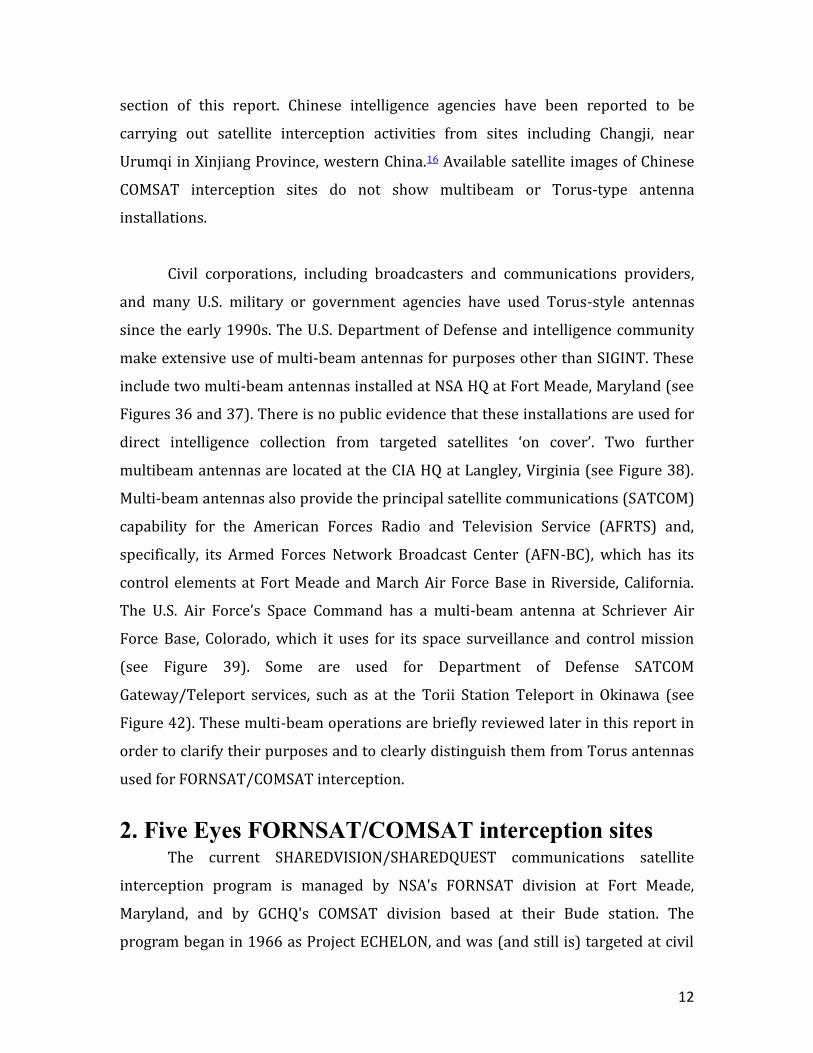
section of this report. Chinese intelligence agencies have been reported to be
carrying out satellite interception activities from sites including Changji, near
Urumqi in Xinjiang Province, western China.16 Available satellite images of Chinese
COMSAT interception sites do not show multibeam or Torus-type antenna
installations.
Civil corporations, including broadcasters and communications providers,
and many U.S. military or government agencies have used Torus-style antennas
since the early 1990s. The U.S. Department of Defense and intelligence community
make extensive use of multi-beam antennas for purposes other than SIGINT. These
include two multi-beam antennas installed at NSA HQ at Fort Meade, Maryland (see
Figures 36 and 37). There is no public evidence that these installations are used for
direct intelligence collection from targeted satellites ‘on cover’. Two further
multibeam antennas are located at the CIA HQ at Langley, Virginia (see Figure 38).
Multi-beam antennas also provide the principal satellite communications (SATCOM)
capability for the American Forces Radio and Television Service (AFRTS) and,
specifically, its Armed Forces Network Broadcast Center (AFN-BC), which has its
control elements at Fort Meade and March Air Force Base in Riverside, California.
The U.S. Air Force’s Space Command has a multi-beam antenna at Schriever Air
Force Base, Colorado, which it uses for its space surveillance and control mission
(see Figure 39). Some are used for Department of Defense SATCOM
Gateway/Teleport services, such as at the Torii Station Teleport in Okinawa (see
Figure 42). These multi-beam operations are briefly reviewed later in this report in
order to clarify their purposes and to clearly distinguish them from Torus antennas
used for FORNSAT/COMSAT interception.
2. Five Eyes FORNSAT/COMSAT interception sites The current SHAREDVISION/SHAREDQUEST communications satellite
interception program is managed by NSA's FORNSAT division at Fort Meade,
Maryland, and by GCHQ's COMSAT division based at their Bude station. The
program began in 1966 as Project ECHELON, and was (and still is) targeted at civil
13
satellite communications, starting with the INTELSAT satellite series first launched
in 1965. A counterpart but distinct NSA program targeting Soviet satellites began at
the same time as ECHELON in 1966. NSA agreed to pay (and still pays for, and owns)
most of the satellite interception equipment used, while its Second Party allies in the
UKUSA alliance agreed to pay personnel, operating and maintenance costs.17
The first ECHELON site, run by GCHQ at Bude, Cornwall, England (covername
CARBOY) was financed by NSA and began operating in 1970. The second ECHELON
site, Yakima Research Station in Washington state, U.S. (covername JACKKNIFE)
started operating in May 1973, and was also targeted on INTELSAT satellites. Bude's
facilities were expanded during the 1980s as CARBOY II, as part of the ECHELON 2
program.18 GCHQ currently operates two other COMSAT collection sites supported
by U.S. funding, at Ayios Nikolaos in eastern Cyprus (covername SOUNDER) and at a
covert site in Oman covernamed LECKWITH. LECKWITH is sited within the
township of Al Maabilah, about three km west of Seeb, on the north coast of Oman
(23.675 N, 58.122 E). The COMSAT function at LECKWITH supplemented earlier
GCHQ activity at multiple sites in Oman.19
Additional ‘Cyber’ functions and construction at LECKWITH for intercepting
multiple fibre cables passing through the Gulf of Oman were added from 2008
onwards as part of GCHQ's Project TEMPORA for acquiring and inputting digital
network intelligence into the XKEYSCORE network. A sequence of DigiGlobe images
of the LECKWITH site taken from 2001 to 2014 show the construction of the
Internet processing facilities (covernamed CIRCUIT) from 2008, and the installation
of a Torus and nine additional COTS small antennas by 2013.20 GCHQ has designated
CIRCUIT as Overseas Processing Centre 1 (OPC-1).
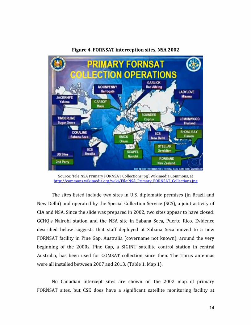
By 2002, according to an NSA slide provided by Edward Snowden (Figure 4)
and published in Brazil in 2013, the expanded FORNSAT network operated by NSA
and UKUSA Second Parties included 16 manned sites around the world, as shown in
Table 1.21
14
Figure 4. FORNSAT interception sites, NSA 2002
Source: ‘File:NSA Primary FORNSAT Collections.jpg’, Wikimedia Commons, at http://commons.wikimedia.org/wiki/File:NSA_Primary_FORNSAT_Collections.jpg
The sites listed include two sites in U.S. diplomatic premises (in Brazil and
New Delhi) and operated by the Special Collection Service (SCS), a joint activity of
CIA and NSA. Since the slide was prepared in 2002, two sites appear to have closed:
GCHQ's Nairobi station and the NSA site in Sabana Seca, Puerto Rico. Evidence
described below suggests that staff deployed at Sabana Seca moved to a new
FORNSAT facility in Pine Gap, Australia (covername not known), around the very
beginning of the 2000s. Pine Gap, a SIGINT satellite control station in central
Australia, has been used for COMSAT collection since then. The Torus antennas
were all installed between 2007 and 2013. (Table 1, Map 1).
No Canadian intercept sites are shown on the 2002 map of primary
FORNSAT sites, but CSE does have a significant satellite monitoring facility at

15
Canadian Forces Station Leitrim, located within the Ottawa city limits. No
multibeam or Torus-type antennas are present at the station, but it does host 13
satellite dishes, all or most of which are likely to have COMSAT missions, and the
station is listed as a source of Internet data in at least one of the Snowden
documents. It appears to have a standard FVEY SIGAD (Sigint Activity Designator),
CAC-98.22 In addition to monitoring satellite communications, the 500 staff at
Leitrim, including 25 U.S. Navy personnel, remotely operate the Canadian intercept
sites at Alert, Gander, and Masset.
First and Second Party FORNSAT/COMSAT sites are supplemented by a large
number of Third Party COMSAT intercept sites operated by 35-40 other nations
linked to NSA, GCHQ and/or other Five Eyes partners through separate and secret
bilateral intelligence co-operation and sharing agreements. Countries known to
operate COMSAT stations and reported to have intelligence sharing agreements
with NSA and/or GCHQ include Spain, Italy, France, Germany, the Netherlands,
Denmark, Sweden, India, Israel, Jordan, Oman, Saudi Arabia, South Africa, and
Switzerland.
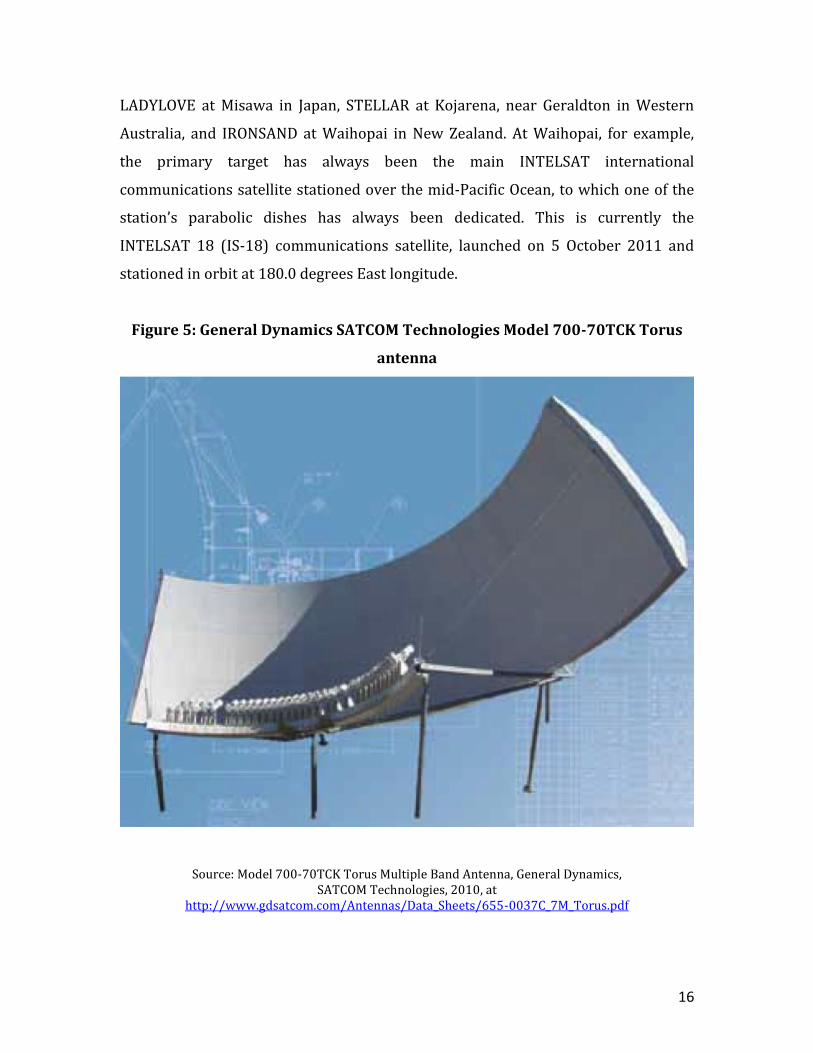
The six Torus-equipped FORNSAT/COMSAT interception sites identified here
appear together to provide complete coverage of the geostationary arc from at least
45 degrees West longitude, over the mid-Atlantic Ocean, to about 160 degrees West
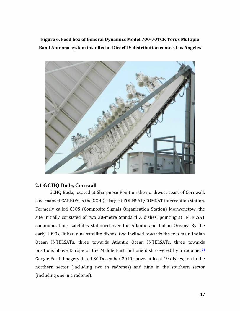
longitude over the mid-Pacific Ocean. The stations are each equipped with Model
700-70TCK Torus Multiple Band Antenna systems, produced by General Dynamics.
(Figures 5 and 6) These measure 24.1 metres wide by 7 metres high, and are curved
spherically in their horizontal plane and parabolically in their vertical plane; they
are able to monitor 35 satellites and hundreds of satellite channels (perhaps as
many as 1,000) simultaneously, in the C-band (3.4-4.2 GHz) and Ku-band (10.95-
12.75 GHz).23
The new Torus network has complemented other FORNSAT collection
activity monitoring high-data-rate multi-beam communications satellites, such as
16
LADYLOVE at Misawa in Japan, STELLAR at Kojarena, near Geraldton in Western
Australia, and IRONSAND at Waihopai in New Zealand. At Waihopai, for example,
the primary target has always been the main INTELSAT international
communications satellite stationed over the mid-Pacific Ocean, to which one of the
station’s parabolic dishes has always been dedicated. This is currently the
INTELSAT 18 (IS-18) communications satellite, launched on 5 October 2011 and
stationed in orbit at 180.0 degrees East longitude.
Figure 5: General Dynamics SATCOM Technologies Model 700-70TCK Torus
antenna
Source: Model 700-70TCK Torus Multiple Band Antenna, General Dynamics, SATCOM Technologies, 2010, at
http://www.gdsatcom.com/Antennas/Data_Sheets/655-0037C_7M_Torus.pdf
17
Figure 6. Feed box of General Dynamics Model 700-70TCK Torus Multiple
Band Antenna system installed at DirectTV distribution centre, Los Angeles
2.1 GCHQ Bude, Cornwall
GCHQ Bude, located at Sharpnose Point on the northwest coast of Cornwall,
covernamed CARBOY, is the GCHQ’s largest FORNSAT/COMSAT interception station.
Formerly called CSOS (Composite Signals Organisation Station) Morwenstow, the
site initially consisted of two 30-metre Standard A dishes, pointing at INTELSAT
communications satellites stationed over the Atlantic and Indian Oceans. By the
early 1990s, ‘it had nine satellite dishes; two inclined towards the two main Indian
Ocean INTELSATs, three towards Atlantic Ocean INTELSATs, three towards
positions above Europe or the Middle East and one dish covered by a radome’.24
Google Earth imagery dated 30 December 2010 shows at least 19 dishes, ten in the
northern sector (including two in radomes) and nine in the southern sector
(including one in a radome).
18
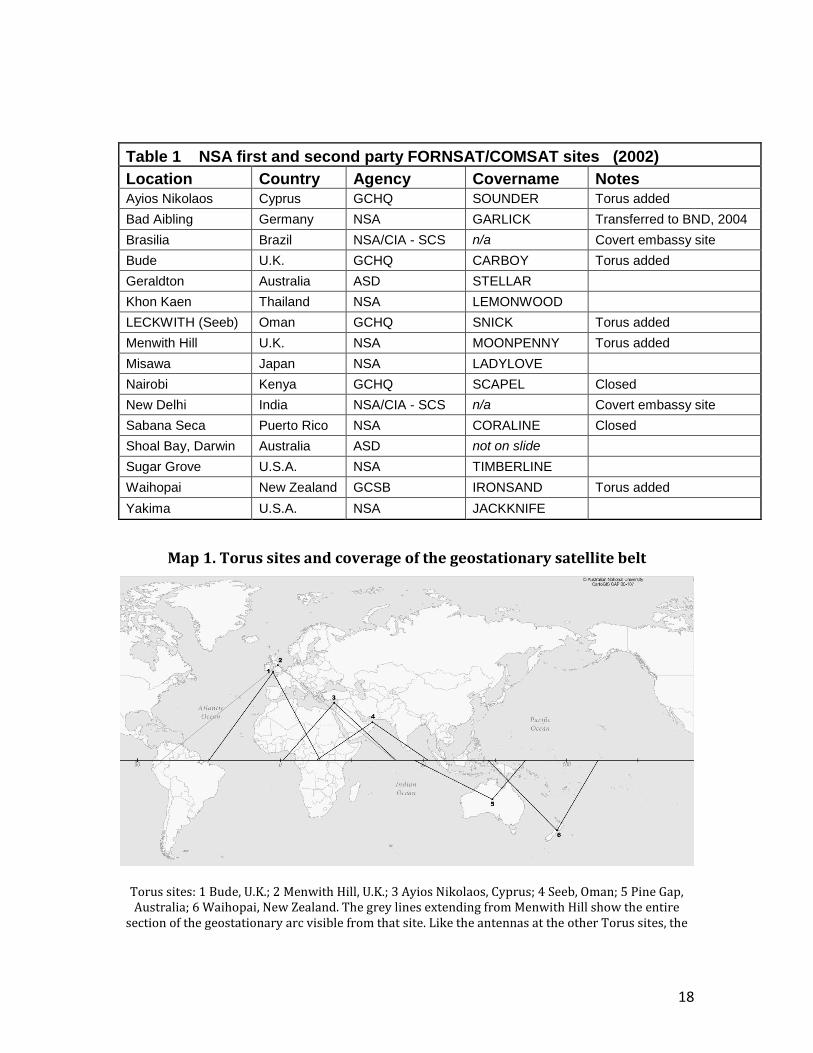
Table 1 NSA first and second party FORNSAT/COMSAT sites (2002)
Location Country Agency Covername Notes
Ayios Nikolaos Cyprus GCHQ SOUNDER Torus added
Bad Aibling Germany NSA GARLICK Transferred to BND, 2004
Brasilia Brazil NSA/CIA - SCS n/a Covert embassy site
Bude U.K. GCHQ CARBOY Torus added
Geraldton Australia ASD STELLAR
Khon Kaen Thailand NSA LEMONWOOD
LECKWITH (Seeb) Oman GCHQ SNICK Torus added
Menwith Hill U.K. NSA MOONPENNY Torus added
Misawa Japan NSA LADYLOVE
Nairobi Kenya GCHQ SCAPEL Closed
New Delhi India NSA/CIA - SCS n/a Covert embassy site
Sabana Seca Puerto Rico NSA CORALINE Closed
Shoal Bay, Darwin Australia ASD not on slide
Sugar Grove U.S.A. NSA TIMBERLINE
Waihopai New Zealand GCSB IRONSAND Torus added
Yakima U.S.A. NSA JACKKNIFE
Map 1. Torus sites and coverage of the geostationary satellite belt
Torus sites: 1 Bude, U.K.; 2 Menwith Hill, U.K.; 3 Ayios Nikolaos, Cyprus; 4 Seeb, Oman; 5 Pine Gap, Australia; 6 Waihopai, New Zealand. The grey lines extending from Menwith Hill show the entire
section of the geostationary arc visible from that site. Like the antennas at the other Torus sites, the
19
Torus at Menwith Hill is capable of monitoring only 70 degrees of the arc. Its orientation cannot be determined because the antenna, uniquely, is inside a radome.
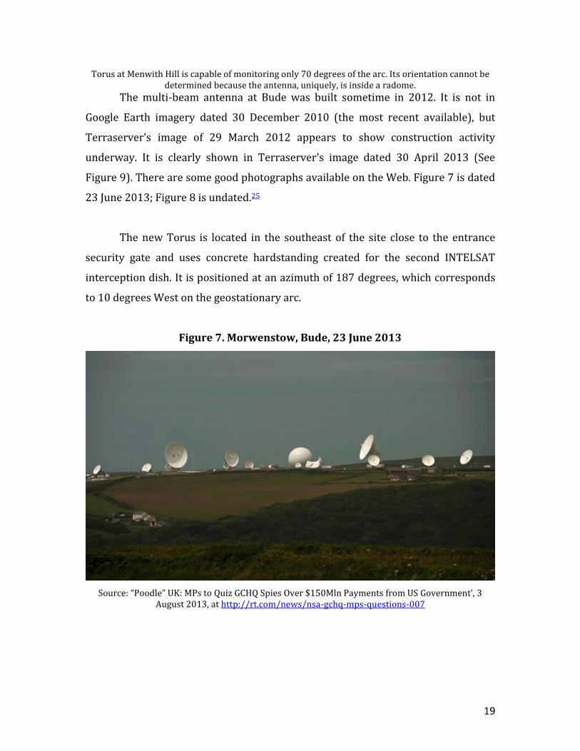
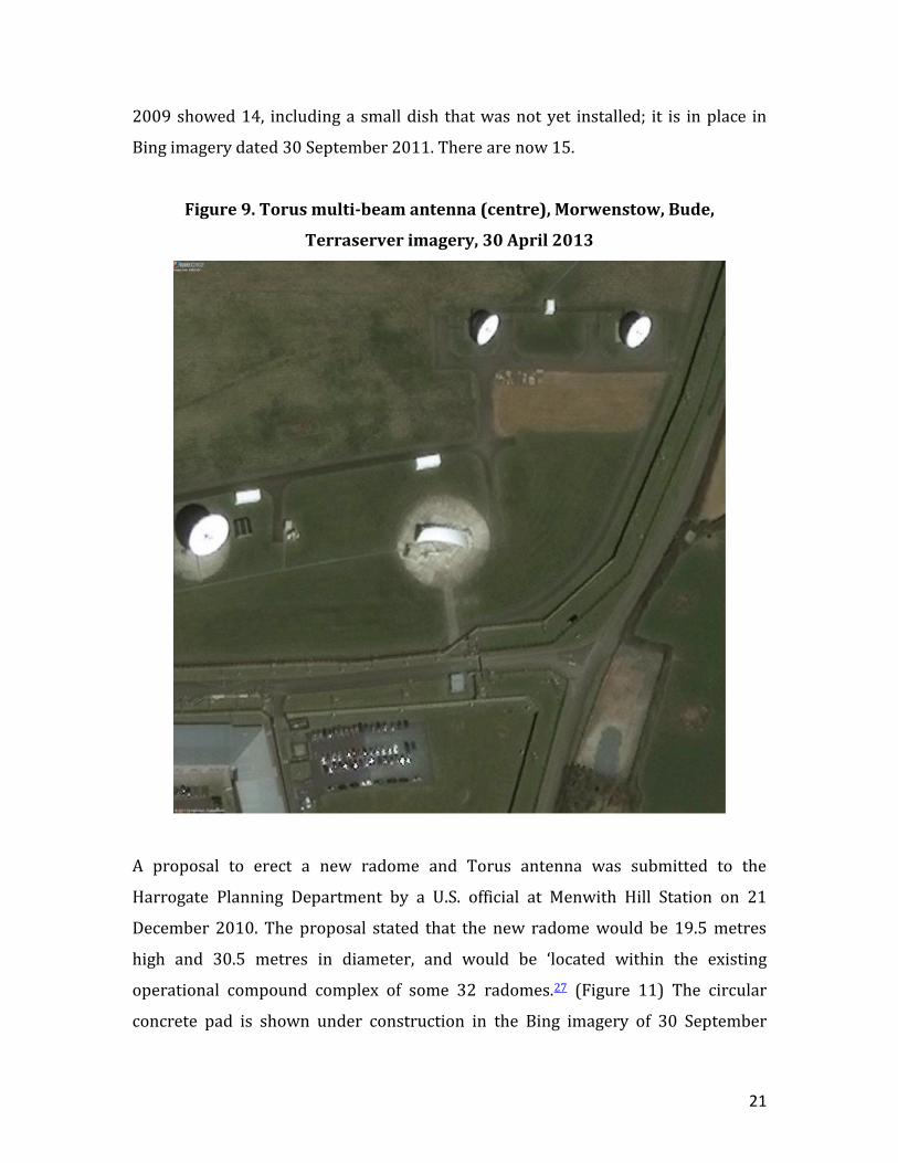
The multi-beam antenna at Bude was built sometime in 2012. It is not in
Google Earth imagery dated 30 December 2010 (the most recent available), but
Terraserver’s image of 29 March 2012 appears to show construction activity
underway. It is clearly shown in Terraserver’s image dated 30 April 2013 (See
Figure 9). There are some good photographs available on the Web. Figure 7 is dated
23 June 2013; Figure 8 is undated.25
The new Torus is located in the southeast of the site close to the entrance
security gate and uses concrete hardstanding created for the second INTELSAT
interception dish. It is positioned at an azimuth of 187 degrees, which corresponds
to 10 degrees West on the geostationary arc.
Figure 7. Morwenstow, Bude, 23 June 2013
Source: “Poodle” UK: MPs to Quiz GCHQ Spies Over $150Mln Payments from US Government’, 3 August 2013, at http://rt.com/news/nsa-gchq-mps-questions-007
20
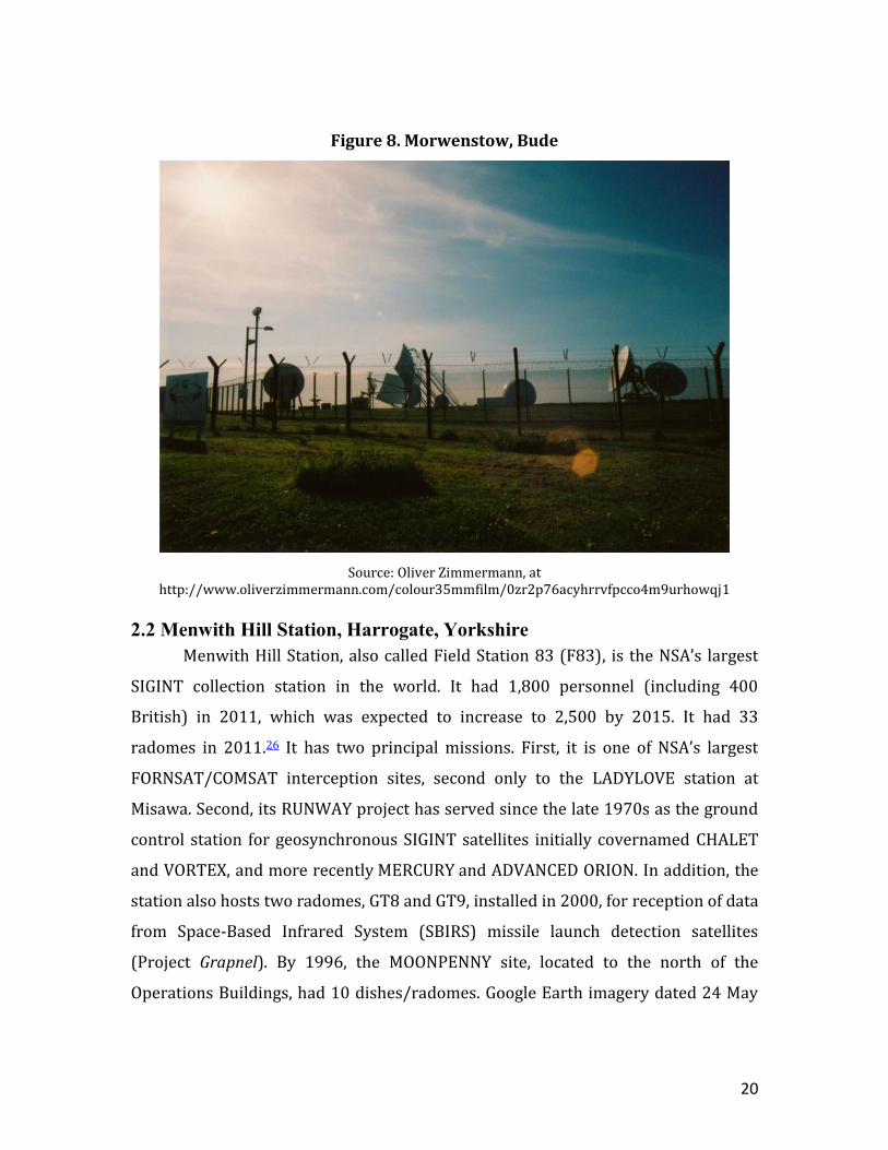
Figure 8. Morwenstow, Bude
Source: Oliver Zimmermann, at http://www.oliverzimmermann.com/colour35mmfilm/0zr2p76acyhrrvfpcco4m9urhowqj1
2.2 Menwith Hill Station, Harrogate, Yorkshire
Menwith Hill Station, also called Field Station 83 (F83), is the NSA’s largest
SIGINT collection station in the world. It had 1,800 personnel (including 400
British) in 2011, which was expected to increase to 2,500 by 2015. It had 33
radomes in 2011.26 It has two principal missions. First, it is one of NSA’s largest
FORNSAT/COMSAT interception sites, second only to the LADYLOVE station at
Misawa. Second, its RUNWAY project has served since the late 1970s as the ground
control station for geosynchronous SIGINT satellites initially covernamed CHALET
and VORTEX, and more recently MERCURY and ADVANCED ORION. In addition, the
station also hosts two radomes, GT8 and GT9, installed in 2000, for reception of data
from Space-Based Infrared System (SBIRS) missile launch detection satellites
(Project Grapnel). By 1996, the MOONPENNY site, located to the north of the
Operations Buildings, had 10 dishes/radomes. Google Earth imagery dated 24 May
21
2009 showed 14, including a small dish that was not yet installed; it is in place in
Bing imagery dated 30 September 2011. There are now 15.
Figure 9. Torus multi-beam antenna (centre), Morwenstow, Bude,
Terraserver imagery, 30 April 2013
A proposal to erect a new radome and Torus antenna was submitted to the
Harrogate Planning Department by a U.S. official at Menwith Hill Station on 21
December 2010. The proposal stated that the new radome would be 19.5 metres
high and 30.5 metres in diameter, and would be ‘located within the existing
operational compound complex of some 32 radomes.27 (Figure 11) The circular
concrete pad is shown under construction in the Bing imagery of 30 September
22
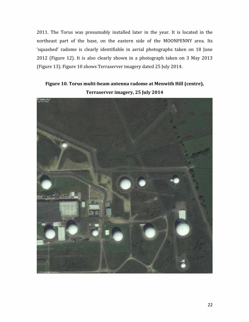
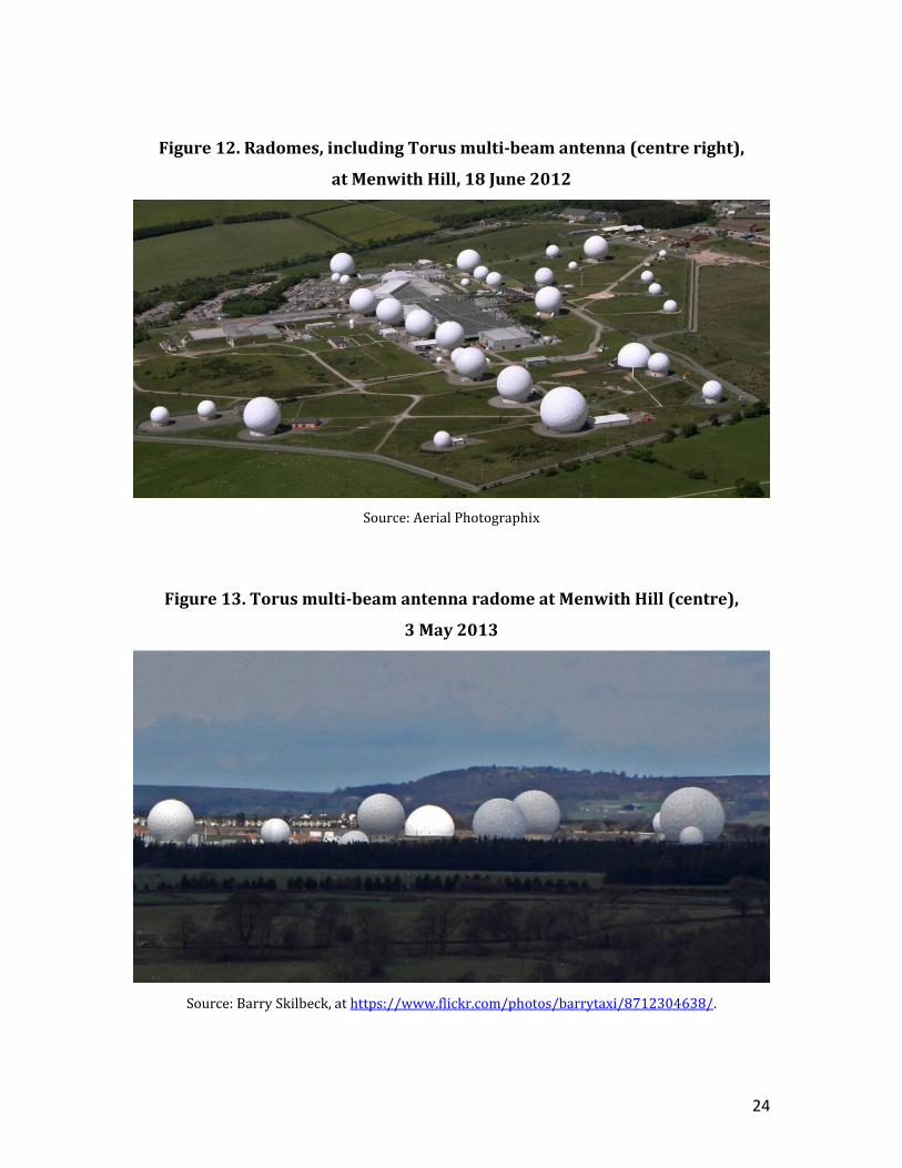
2011. The Torus was presumably installed later in the year. It is located in the
northeast part of the base, on the eastern side of the MOONPENNY area. Its
‘squashed’ radome is clearly identifiable in aerial photographs taken on 18 June
2012 (Figure 12). It is also clearly shown in a photograph taken on 3 May 2013
(Figure 13). Figure 10 shows Terraserver imagery dated 25 July 2014.
Figure 10. Torus multi-beam antenna radome at Menwith Hill (centre),
Terraserver imagery, 25 July 2014
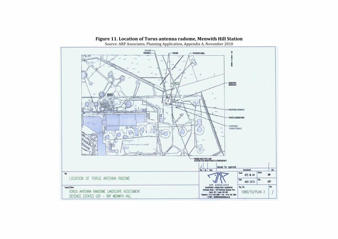
Figure 11. Location of Torus antenna radome, Menwith Hill Station Source: ARP Associates, Planning Application, Appendix A, November 2010
24
Figure 12. Radomes, including Torus multi-beam antenna (centre right),
at Menwith Hill, 18 June 2012
Source: Aerial Photographix
Figure 13. Torus multi-beam antenna radome at Menwith Hill (centre),
3 May 2013
Source: Barry Skilbeck, at https://www.flickr.com/photos/barrytaxi/8712304638/.
25
The orientation of the Torus antenna inside the radome is unknown.
Assuming it was pointed directly south, its coverage along the geobelt would be
little different, just a few degrees eastwards, from that of the GCHQ Torus system
installed at Bude a year or so later. If it was pointed towards the southwest, it could
potentially extend coverage out to around 70 degrees West over South America,
while if it was pointed towards the southeast it could extend coverage out to around
70 degrees East, effectively duplicating that of the Torus system at Ayios Nikolaos in
Cyprus. By providing overlapping coverage across much of the equatorial arcs in
view from Bude and Oman, the Five Eyes would expect to be able fully to cover
multiple closely spaced satellite targets.
2.3 Ayios Nikolaos, Cyprus
GCHQ operates a major FORNSAT site in Cyprus, covernamed SOUNDER, and
located at Ayios Nikolaos in the U.K.’s Eastern Sovereign Base Area, near Famagusta.
It provides high frequency collection for Five Eyes' global Wideband GLAIVE
terrestrial radio (HF) interception system and inputs to the associated shared geo-
location network, BORESIGHT. Ayios Nikolaos also operates a remote VHF, UHF and
space collection site high in the Troodos mountain range of Cyprus, and provides
(separately) the receiving site for the COBRA SHOE U.S. Air Force over the horizon
(OTH) radar system using three giant arrays sited to the southeast of the SOUNDER
area. The SOUNDER project was discussed at a meeting between General William
Odom and Peter Marychurch, directors of the NSA and GCHQ, in 1988, at which it
was agreed that NSA ‘will share part of costs’.28 The Torus multi-beam antenna at
SOUNDER appears to have been installed between 2008 and 2010. It was not
present in Google Earth imagery dated 28 May 2008, but it is shown in a
Terraserver image dated 16 August 2010. The first Google Earth imagery showing
the new antenna is dated 11 April 2011.
The Torus antenna is located in the northwest part of the main COMSAT
compound, south of the old Pusher CDAA. (Figures 14 and 15) Google Earth imagery
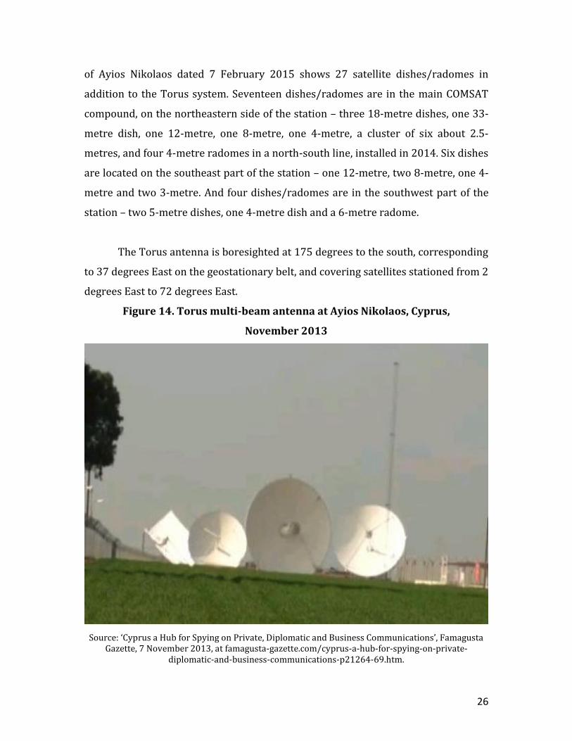
26
of Ayios Nikolaos dated 7 February 2015 shows 27 satellite dishes/radomes in
addition to the Torus system. Seventeen dishes/radomes are in the main COMSAT
compound, on the northeastern side of the station – three 18-metre dishes, one 33-
metre dish, one 12-metre, one 8-metre, one 4-metre, a cluster of six about 2.5-
metres, and four 4-metre radomes in a north-south line, installed in 2014. Six dishes
are located on the southeast part of the station – one 12-metre, two 8-metre, one 4-
metre and two 3-metre. And four dishes/radomes are in the southwest part of the
station – two 5-metre dishes, one 4-metre dish and a 6-metre radome.
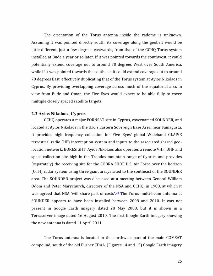
The Torus antenna is boresighted at 175 degrees to the south, corresponding
to 37 degrees East on the geostationary belt, and covering satellites stationed from 2
degrees East to 72 degrees East.
Figure 14. Torus multi-beam antenna at Ayios Nikolaos, Cyprus,
November 2013
Source: ‘Cyprus a Hub for Spying on Private, Diplomatic and Business Communications’, Famagusta Gazette, 7 November 2013, at famagusta-gazette.com/cyprus-a-hub-for-spying-on-private-
diplomatic-and-business-communications-p21264-69.htm.
27
Figure 15. Torus multi-beam antenna (top left) at Ayios Nikolaos, Cyprus,
Google Earth imagery, 21 May 2013
28
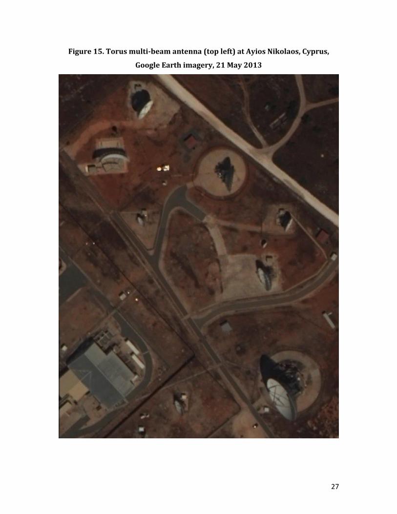
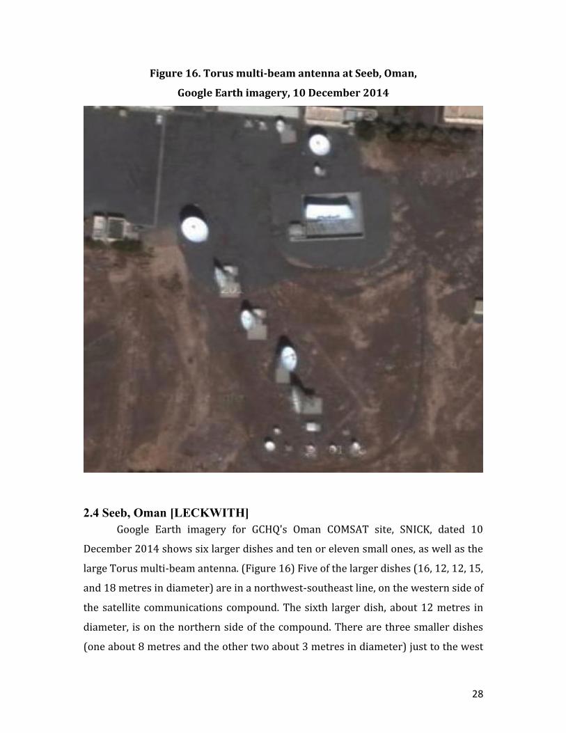
Figure 16. Torus multi-beam antenna at Seeb, Oman,
Google Earth imagery, 10 December 2014
2.4 Seeb, Oman [LECKWITH]
Google Earth imagery for GCHQ's Oman COMSAT site, SNICK, dated 10
December 2014 shows six larger dishes and ten or eleven small ones, as well as the
large Torus multi-beam antenna. (Figure 16) Five of the larger dishes (16, 12, 12, 15,
and 18 metres in diameter) are in a northwest-southeast line, on the western side of
the satellite communications compound. The sixth larger dish, about 12 metres in
diameter, is on the northern side of the compound. There are three smaller dishes
(one about 8 metres and the other two about 3 metres in diameter) just to the west
29
of this 12-metre dish, and a 5-metre dish between this dish and the Torus antenna.
Just south of the line of five larger dishes are two 5-metre dishes and 4 or 5 with
diameters of only 2-3 metres.
The Torus antenna was installed in 2012. It is present in the Google Earth
image dated 11 December 2012, but not present in the Terraserver image dated 12
October 2011. It is oriented almost directly to the south, corresponding to 58
degrees East on the geostationary belt, and covering satellites stationed at from
about 23 degrees East to about 73 degrees East.
2.5 Pine Gap, Northern Territory, Australia
The Pine Gap satellite ground station is located about 19 km southwest of
Alice Springs in central Australia. Managed by the U.S. National Reconnaissance
Office (NRO), its original and still principal purpose is to serve as the ground control
station for geosynchronous signals intelligence (SIGINT) satellites developed by the
U.S. Central Intelligence Agency (CIA); it probably remains the CIA’s most important
technical intelligence collection station in the world. The first of the CIA’s
geostationary SIGINT satellites, then called RHYOLITE, was launched on 19 June
1970. Its successors have been called AQUACADE, MAGNUM, ORION and
ADVANCED ORION. Increasing numbers of civilian NSA personnel joined the activity
through the 1990s. A reorganisation of the management structure in 1997
established Special Collection Elements (SCEs), comprising personnel from not only
the CIA but also the NSA and Service Cryptological Agencies (SCAs). In the case of
the U.S. Navy, for example, an Information Operations Detachment was established,
with three officers and 40 enlisted men, in March 1998. A detachment of the U.S.
Army’s 743rd Military Intelligence Battalion, a detachment of the U.S. Air Force’s Air
Intelligence Agency’s Intelligence Operations Group (IOG), and a sub-unit of the U.S.
Marines’ Cryptologic Support Battalion were also posted to Pine Gap in the late
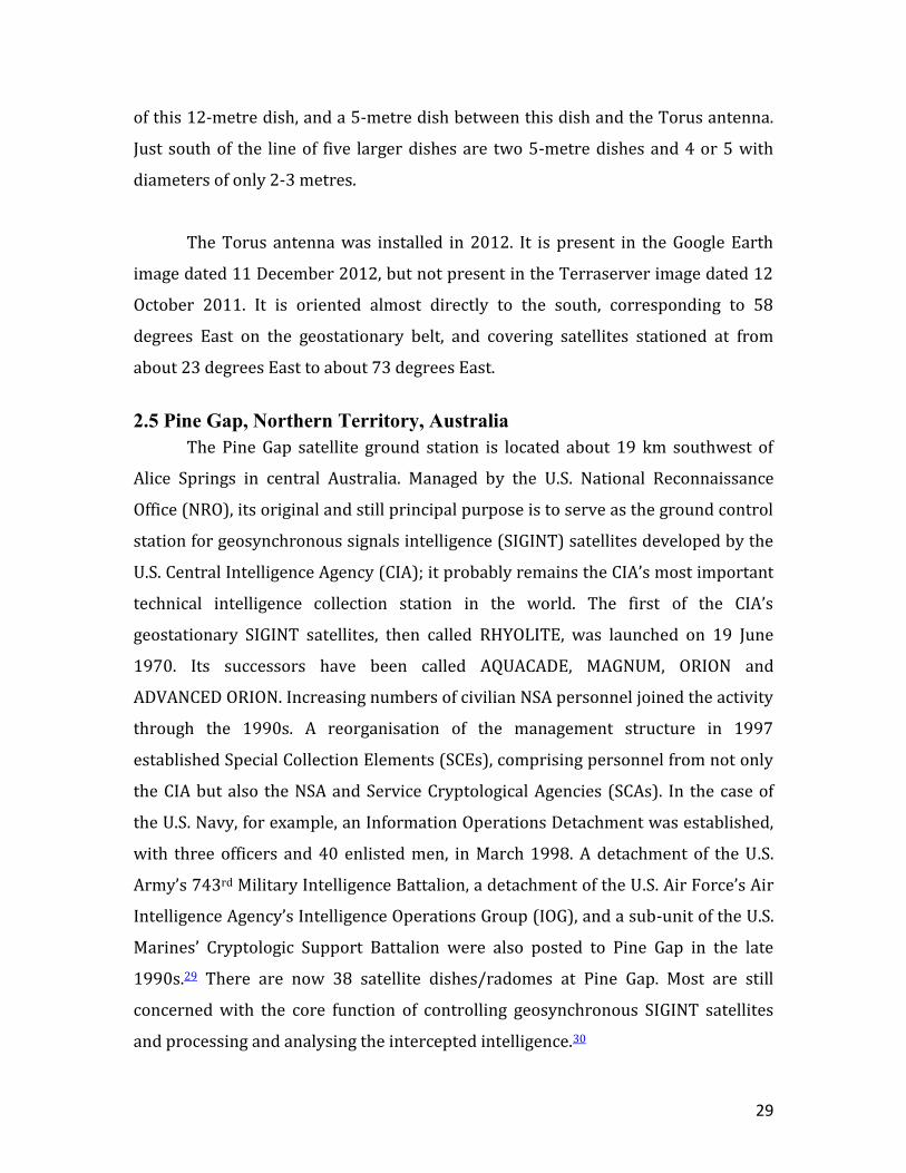
1990s.29 There are now 38 satellite dishes/radomes at Pine Gap. Most are still
concerned with the core function of controlling geosynchronous SIGINT satellites
and processing and analysing the intercepted intelligence.30
30
On 1 October 1999, the U.S. Air Force officially opened a Relay Ground
Station (RGS), which relays data from U.S. missile launch detection/early warning
satellites – formerly called the Defense Support Program (DSP) but now the Space-
Based Infrared System (SBIRS) – to both U.S. and Australian HQs and command
centres. (It replaced the USAF’s DSP ground control station at Nurrungar). Six of the
satellite terminals at Pine Gap (four in radomes and two unshielded) belong to the
RGS. Another three radomes are probably associated with the U.S. Missile Defense
Agency’s Space Tracking and Surveillance System (STSS).
Figure 17. Multi-beam antenna compound, Pine Gap, Terraserver imagery,
January 2010
31
Pine Gap appears to have acquired a FORNSAT/COMSAT interception
function in the early 2000s. This was probably presaged with the arrival of SCA
elements at the end of the 1990s. Two 23-metre dishes suitable for COMSAT SIGINT
Development (Sigdev) were installed inside 30-metre radomes in 1999-2000. Of
significant interest, it appears that Detachment 2 of the U.S. Air Force’s Air
Intelligence Agency’s 544th Intelligence Operations Group, previously located at the
U.S. FORNSAT station at Sabana Seca, Puerto Rico, was transferred to Pine Gap in the
early 2000s. Detachment 2 ceased operations at Sabana Seca around 2000. The site
was officially disestablished on 31 January 2003. The CORALINE COMSAT
interception dishes/radomes were dismantled in 2004. We infer that the transfer of
Detachment 2 from Sabana Seca to Pine Gap signified that Pine Gap had become a
new FORNSAT site.31
From August 2005 to July 2007, Detachment 2 of the 544th IOG at Pine Gap
comprised 28 personnel.32 The detachment includes a Geospatial Metadata Analysis
unit which ‘optimizes information flow to the warfighter’, and especially Special
Operations Forces teams.33 The unit is now designated Detachment 1 of the 566th
Intelligence Squadron at Buckley AFB, under the 544th Intelligence, Surveillance and
Reconnaissance Group (ISRG) at Peterson AFB in Colorado Springs.34
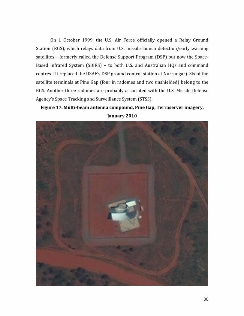
A Torus multi-beam antenna was installed at Pine Gap in 2008. It is located a
little more than 200 metres south of the main compound in an entirely separate
fenced compound measuring 55 m x 50 m. It was the first satellite antenna at Pine
Gap to be located outside the principal antenna compound. The antenna is installed
on top of a concrete pad approximately 17 metres wide, and is fixed on top of a steel
frame, next to a small building. (Figures 17 and 18)
The antenna faces north-northwest, boresighted at 329 degrees towards the
equator, corresponding to 120 degrees East on the geostationary belt. Its purview
extends from about 85 degrees East to about 155 degrees East longitudes, fitting the
gap between Seeb and Waihopai.
32
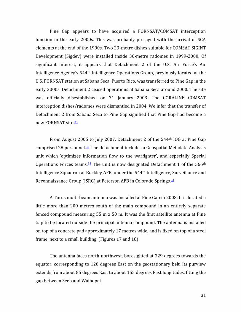
Figure 18. Pine Gap, with multi-beam antenna at rear, 12 October 2013
Source: Richard Tanter
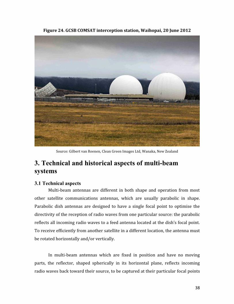
2.6 Waihopai, New Zealand
The GCSB FORNSAT/COMSAT interception station, covernamed IRONSAND,
is located at Waihopai, near Blenheim, in the northeast part of New Zealand’s South
Island. It features two 18-metre parabolic dishes, mounted on 8-metre pedestals
and covered by 33-metre radomes. These were installed in 1989 and 1995. The first
dish has always been focussed on the primary INTELSAT communications satellite
stationed over the mid-Pacific, beginning with IS-510, which had been launched in
1985 and was stationed at 174 degrees East; it carried 26 C-band and 6 Ku-band
transponders, providing 15,000 voice circuits. On 15 January 1994, the station
transitioned to IS-701, which was launched in October 1993 and which replaced IS-
510 at 174 degrees East; it carried 26 C-band and 10 Ku-band transponders, with
33
96,000 voice circuits.35 At the beginning of 2012, the station moved to IS-18,
launched in October 2011 and placed at 180 degrees East, replacing IS-701 as
INTELSAT’s primary satellite over the Pacific.36 It has 24 C-band and 12 Ku-band
transponders.
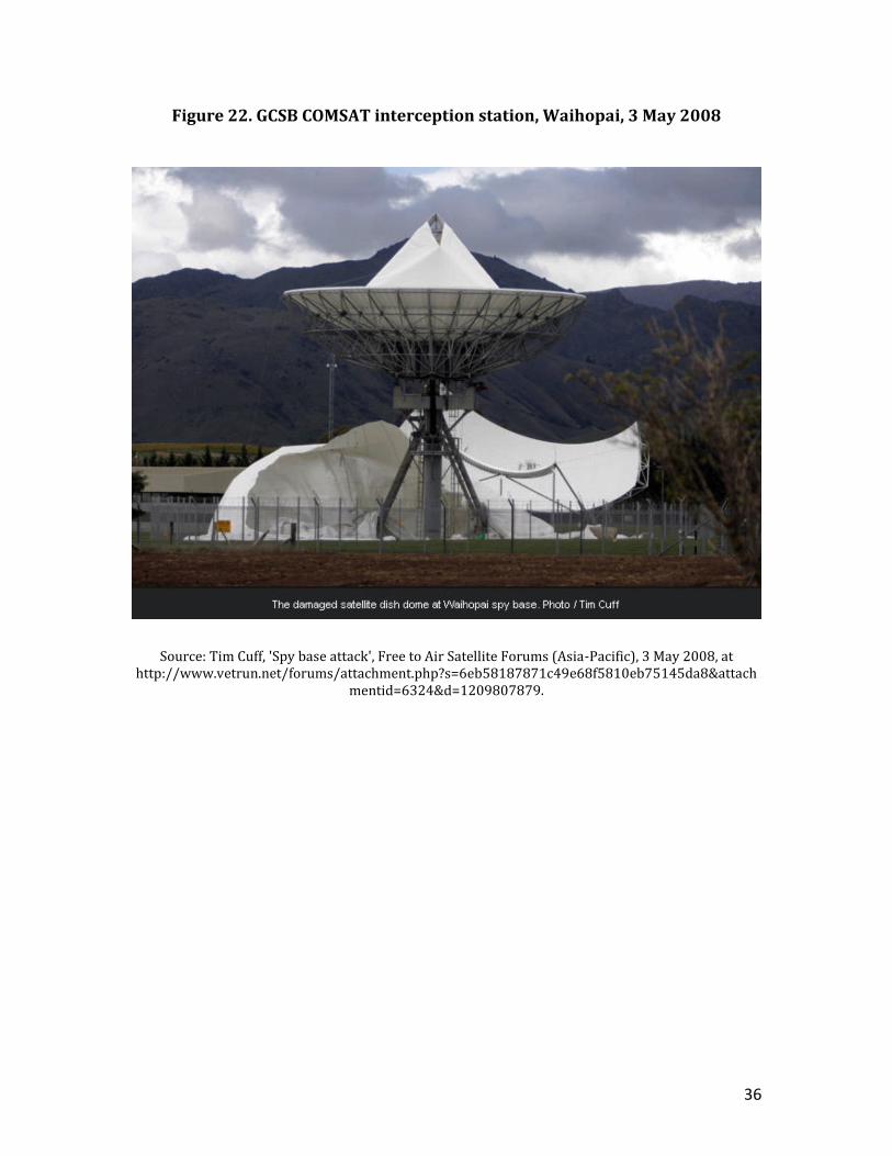
The second dish, uncovered for 15 months from April 2008, when anti-war
protesters destroyed the radome, was not fixed on one satellite, but shifted between
satellites for periods of weeks or months. However, it always pointed towards East
Asian rather than Pacific satellites. On 10 July 2009, for example, it was pointed to
132 degrees East.37 It was probably monitoring a Japanese communications satellite,
JCSAT-5A, but may have been monitoring Vietnam’s first communications satellite,
Vinasat 1, stationed nearby.
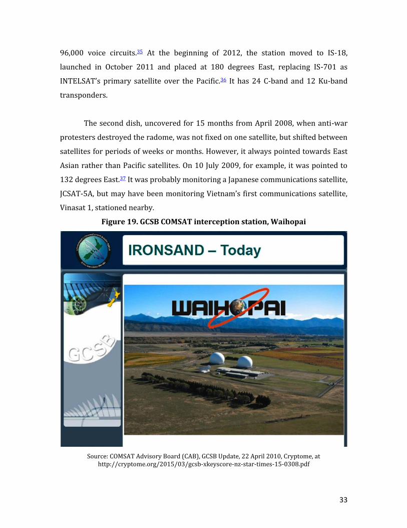
Figure 19. GCSB COMSAT interception station, Waihopai
Source: COMSAT Advisory Board (CAB), GCSB Update, 22 April 2010, Cryptome, at http://cryptome.org/2015/03/gcsb-xkeyscore-nz-star-times-15-0308.pdf
34
The Torus antenna was installed about June 2007 and was scheduled to be
‘up and running’ around September/October 2007. According to Air Marshal Bruce
Ferguson, the then Director of the GCSB, the new antenna cost less than $1 million
and ‘was very good value for money’. He said that: ‘It’s simply an enhancement of
our capabilities. It’s a new, modern aerial which will increase our ability to conduct
the tasks we do’. He said that unlike the previous two dishes, which were covered by
radomes ‘to ward off the weather’, the new Torus antenna would ‘remain in the
open’.38
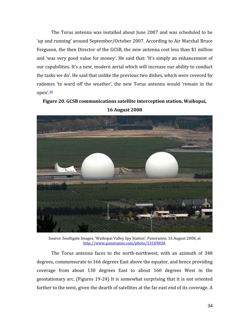
Figure 20. GCSB communications satellite interception station, Waihopai,
16 August 2008
Source: Southgate Images, 'Waihopai Valley Spy Station', Panoramio, 16 August 2008, at http://www.panoramio.com/photo/13169830.
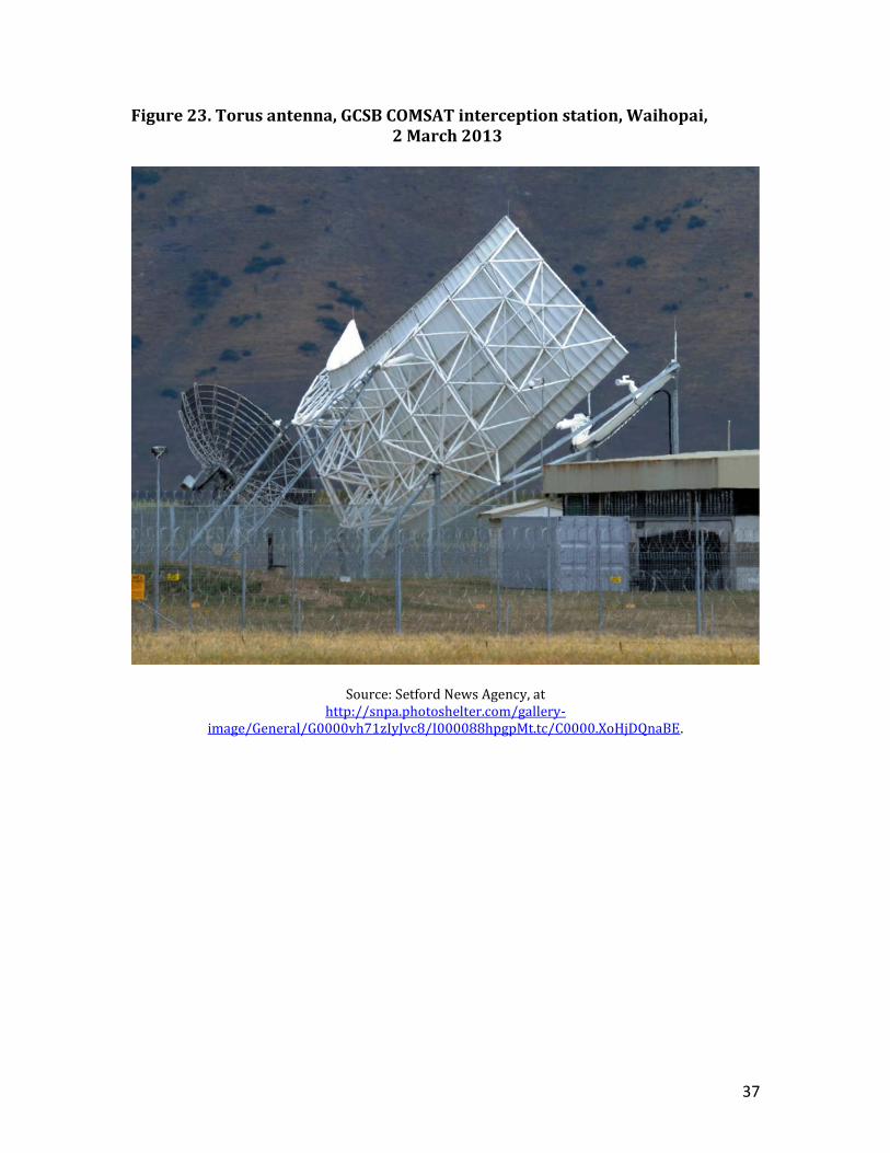
The Torus antenna faces to the north-northwest, with an azimuth of 348
degrees, commensurate to 166 degrees East above the equator, and hence providing
coverage from about 130 degrees East to about 160 degrees West in the
geostationary arc. (Figures 19-24) It is somewhat surprising that it is not oriented
further to the west, given the dearth of satellites at the far east end of its coverage. A
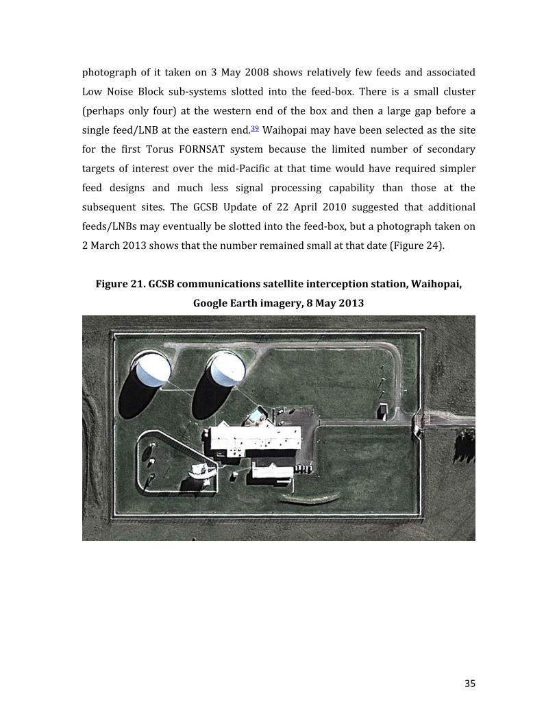
35
photograph of it taken on 3 May 2008 shows relatively few feeds and associated
Low Noise Block sub-systems slotted into the feed-box. There is a small cluster
(perhaps only four) at the western end of the box and then a large gap before a
single feed/LNB at the eastern end.39 Waihopai may have been selected as the site
for the first Torus FORNSAT system because the limited number of secondary
targets of interest over the mid-Pacific at that time would have required simpler
feed designs and much less signal processing capability than those at the
subsequent sites. The GCSB Update of 22 April 2010 suggested that additional
feeds/LNBs may eventually be slotted into the feed-box, but a photograph taken on
2 March 2013 shows that the number remained small at that date (Figure 24).
Figure 21. GCSB communications satellite interception station, Waihopai,
Google Earth imagery, 8 May 2013
36
Figure 22. GCSB COMSAT interception station, Waihopai, 3 May 2008
Source: Tim Cuff, 'Spy base attack', Free to Air Satellite Forums (Asia-Pacific), 3 May 2008, at
http://www.vetrun.net/forums/attachment.php?s=6eb58187871c49e68f5810eb75145da8&attachmentid=6324&d=1209807879.
37
Figure 23. Torus antenna, GCSB COMSAT interception station, Waihopai, 2 March 2013
Source: Setford News Agency, at http://snpa.photoshelter.com/gallery-
image/General/G0000vh71zIyJvc8/I000088hpgpMt.tc/C0000.XoHjDQnaBE.
38
Figure 24. GCSB COMSAT interception station, Waihopai, 20 June 2012
Source: Gilbert van Reenen, Clean Green Images Ltd, Wanaka, New Zealand
3. Technical and historical aspects of multi-beam
systems
3.1 Technical aspects
Multi-beam antennas are different in both shape and operation from most
other satellite communications antennas, which are usually parabolic in shape.
Parabolic dish antennas are designed to have a single focal point to optimise the
directivity of the reception of radio waves from one particular source: the parabolic
reflects all incoming radio waves to a feed antenna located at the dish’s focal point.
To receive efficiently from another satellite in a different location, the antenna must
be rotated horizontally and/or vertically.
In multi-beam antennas which are fixed in position and have no moving
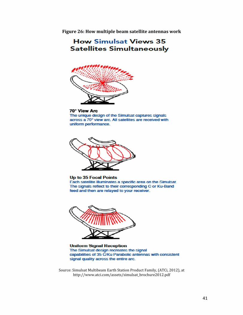
parts, the reflector, shaped spherically in its horizontal plane, reflects incoming
radio waves back toward their source, to be captured at their particular focal points
39
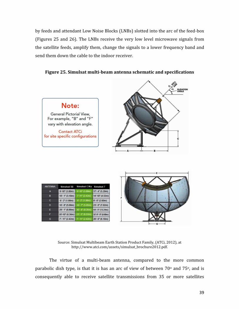
by feeds and attendant Low Noise Blocks (LNBs) slotted into the arc of the feed-box
(Figures 25 and 26). The LNBs receive the very low level microwave signals from
the satellite feeds, amplify them, change the signals to a lower frequency band and
send them down the cable to the indoor receiver.
Figure 25. Simulsat multi-beam antenna schematic and specifications
Source: Simulsat Multibeam Earth Station Product Family, (ATCi, 2012), at http://www.atci.com/assets/simulsat_brochure2012.pdf.
The virtue of a multi-beam antenna, compared to the more common
parabolic dish type, is that it is has an arc of view of between 70o and 75o, and is
consequently able to receive satellite transmissions from 35 or more satellites
40
simultaneously without degradation in performance (given a nominal separation
between satellites of 2 degrees).40 Moreover, a large number of transponders on all
of these satellites can each be monitored simultaneously, meaning, for example, that
even a smaller commercial ATCi-manufactured Simulsat antenna of this type can
receive almost 1,000 satellite channels simultaneously (compared with 24-32
simultaneously received channels for a comparable parabolic antenna).41
In practice, many geostationary satellites are closer than 2 degrees apart.
Indeed, with more than 400 active satellites currently in geostationary orbit, the
average separation is only 0.87 degrees.42 Comprehensive coverage of all satellites
in some 70o segments of the geostationary belt therefore requires more than one
multi-beam system.
A major disadvantage of Simulsat-type antennas is that maintenance of
systematic coverage of the relevant purview, keeping abreast of all new satellite
launches, requires frequent re-peaking of the feeds and sometimes re-alignment of
the antenna itself. Minor adjustments can be done by hand, using ‘only a satellite
receiver and video monitor and peaking to minimize noise in the video’. However, it
is usually best to use a spectrum analyser, attached to the LNBs, to ‘optimize signal
strength’.43 ATCi has produced a line of spectrum analysers for this purpose (the
TE900, the TE1200, the TE2000HD and, introduced in January 2015, the TE3000).
Sooner or later, systematic monitoring efforts require re-peaking of all of the
feeds/LNBs across the whole feed-box. This usually takes a contractor-provided
field technician about two days to perform.
Realignment of the Simulsat antenna to a new 70o arc is usually done every
several years, depending on the rapidity of changes in satellite positions. It involves
using a crane to raise the reflector assembly from the mount and change its roll
angle and elevation angle to the desired values, and pivoting the mount to the new
azimuth angle. The ATCi Simulsat mount ‘affords ± 10o of azimuth adjustment’. In
some cases, the desired azimuth is sufficiently different from the previous azimuth
as to require re-setting of the mount and its concrete support pad. The final step in
41
Figure 26: How multiple beam satellite antennas work
Source: Simulsat Multibeam Earth Station Product Family, (ATCi, 2012), at http://www.atci.com/assets/simulsat_brochure2012.pdf
42
the realignment process is to adjust each of the feeds/LNBs ‘for the desired 70o
satellite view’ so that they ‘peak within the confines of the feed box’.44
3.2 Historical development for orthodox satellite reception
Torus multi-beam antenna designs were pioneered by Comsat Laboratories
at Clarksburg, Maryland, in the 1970s. An experimental Torus system, 16.5 metres
wide and 9.6 metres high, was installed at Clarksburg in 1973. It was able to receive
transmissions from ‘as many as seven’ communications satellites simultaneously.45
A two-volume, 420-page technical study prepared by COMSAT Laboratories for the
Defense Communications Agency (DCA) in March 1977 showed that four
appropriately-spaced Torus sites (for example, at Saint Margaret near Nairobi,
Sweden, Iceland and Ascension Island) provided communications with all the LES-9,
FLTSATCOM, NATO-II, NATO-III and DSCS satellites then in geostationary orbit. It
noted, however, that ‘a major disadvantage of the fixed reflector MBTA [Multi-beam
Torus Antenna] is the lack of pointing flexibility’, hence constraining it to satellites
in well-defined orbital positions within ‘a fixed position of the geosynchronous
arc’.46
A report by a COMSAT engineer in 1982 noted that there were 16 satellites in
orbit in the 70-143° geostationary arc at that time, three Canadian and thirteen U.S.
domestic communications satellites, and that this was expected to increase to 27 by
1985. The total U.S. domestic communications satellite capacity in orbit amounted
to about 250 transponders in 1982, and was expected to exceed 400 by 1985. It
provided ‘technical details, specifications and test data on the SatCom Technologies
4.5 meter Torus antenna’, and suggested that one of these could provide
simultaneous reception of a large proportion of this traffic well into the 1980s.47
In 1981, COMSAT Corp reached an agreement with Radiation Systems Inc
(RSI) which allowed the latter to manufacture and sell a variety of Torus multi-beam
43
antennas, ranging in size from 3 to 8.5 metres.48 RSI was acquired by COMSAT Corp
in 1994. In 1998-2000, RSI was amalgamated with Vertex Communications Inc,
forming VertexRSI, which produced a highly regarded 7-metre Torus multi-beam
antenna system. VertexRSI was acquired by General Dynamics SATCOM Tech-
nologies in 2004.
Several other companies also entered the multi-beam market in the 1980s, of
which the most important was Antenna Technology Communications Inc (ATCi),
based in Chandler, Arizona. By the mid-1980s, ATCi had emerged as a leader in the
design of small Simulsat [Simultaneous Multiple Satellites] antennas, producing two
principal models, the Simulsat 5 and Simulsat 7 systems, each with several variants
in antenna dimensions.49
GTE Communications Products Corp was also interested in the new
technology in the early 1980s. For example, it produced a study of the design and
performance of a Torus multi-beam antenna for the U.S. Army Satellite
Communications Agency at Fort Monmouth, New Jersey, the results of which were
published in March 1984.50
The first U.S. Department of Defense agency to deploy Simulsat multi-beam
antennas for its core mission was the Armed Forces Radio and Television Service
(AFRTS). It installed two ATCi Simulsat antennas at its Broadcast Center (AFRTS-
BC) at Sun Valley in California in the 1980s. One was a 7-meter receive-only
reflector, set on a 60- x 40-foot foundation; the other was a 5-meter receive-only
reflector on a 50- x 25-foot foundation.51 A report by the Department of the Air
Force in February 1995 stated that the AFRTS was ‘a DoD field activity under the
direction of the Assistant to the Secretary of Defense for Public Affairs’ and that its
mission ‘is to provide radio and television news, sports, religious, information and
entertainment programming to 1 million DoD personnel and their families stationed
overseas or at sea where English language broadcast service is unavailable or
inadequate’.52
44
4. Russian and Ukrainian multi-beam communications
interception antennas
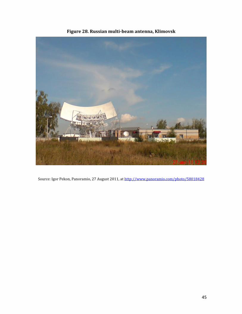
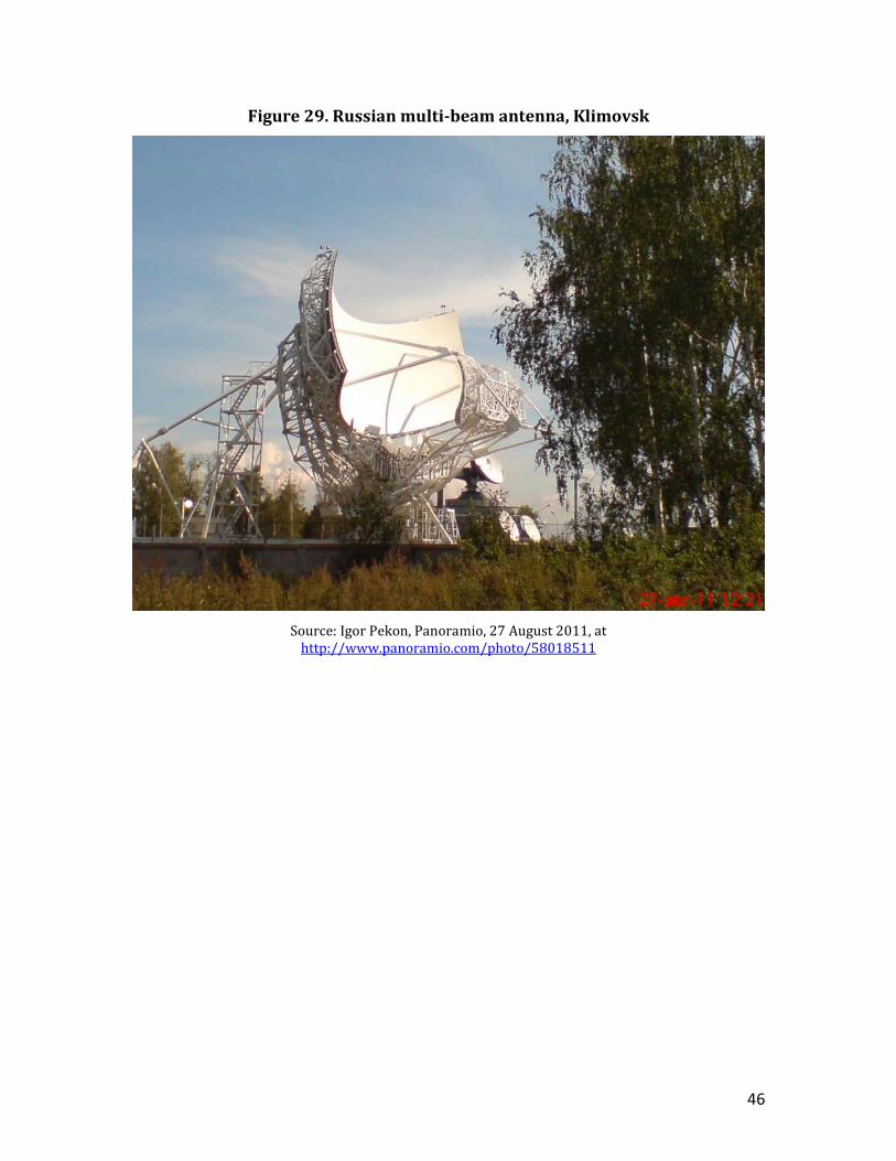
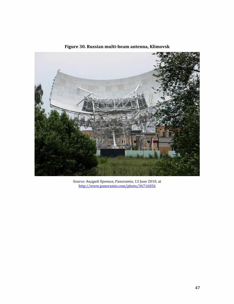
4.1 Russian multi-beam system, Klimovsk
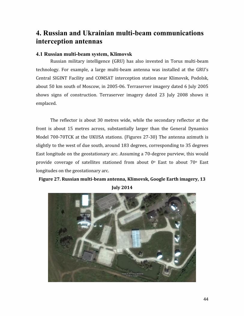
Russian military intelligence (GRU) has also invested in Torus multi-beam
technology. For example, a large multi-beam antenna was installed at the GRU’s
Central SIGINT Facility and COMSAT interception station near Klimovsk, Podolsk,
about 50 km south of Moscow, in 2005-06. Terraserver imagery dated 6 July 2005
shows signs of construction. Terraserver imagery dated 23 July 2008 shows it
emplaced.
The reflector is about 30 metres wide, while the secondary reflector at the
front is about 15 metres across, substantially larger than the General Dynamics
Model 700-70TCK at the UKUSA stations. (Figures 27-30) The antenna azimuth is
slightly to the west of due south, around 183 degrees, corresponding to 35 degrees
East longitude on the geostationary arc. Assuming a 70-degree purview, this would
provide coverage of satellites stationed from about 0o East to about 70o East
longitudes on the geostationary arc.
Figure 27. Russian multi-beam antenna, Klimovsk, Google Earth imagery, 13
July 2014
45
Figure 28. Russian multi-beam antenna, Klimovsk
Source: Igor Pekon, Panoramio, 27 August 2011, at http://www.panoramio.com/photo/58018428
46
Figure 29. Russian multi-beam antenna, Klimovsk
Source: Igor Pekon, Panoramio, 27 August 2011, at http://www.panoramio.com/photo/58018511
47
Figure 30. Russian multi-beam antenna, Klimovsk
Source: Андрей Хромых, Panoramio, 13 June 2010, at http://www.panoramio.com/photo/36716056
48
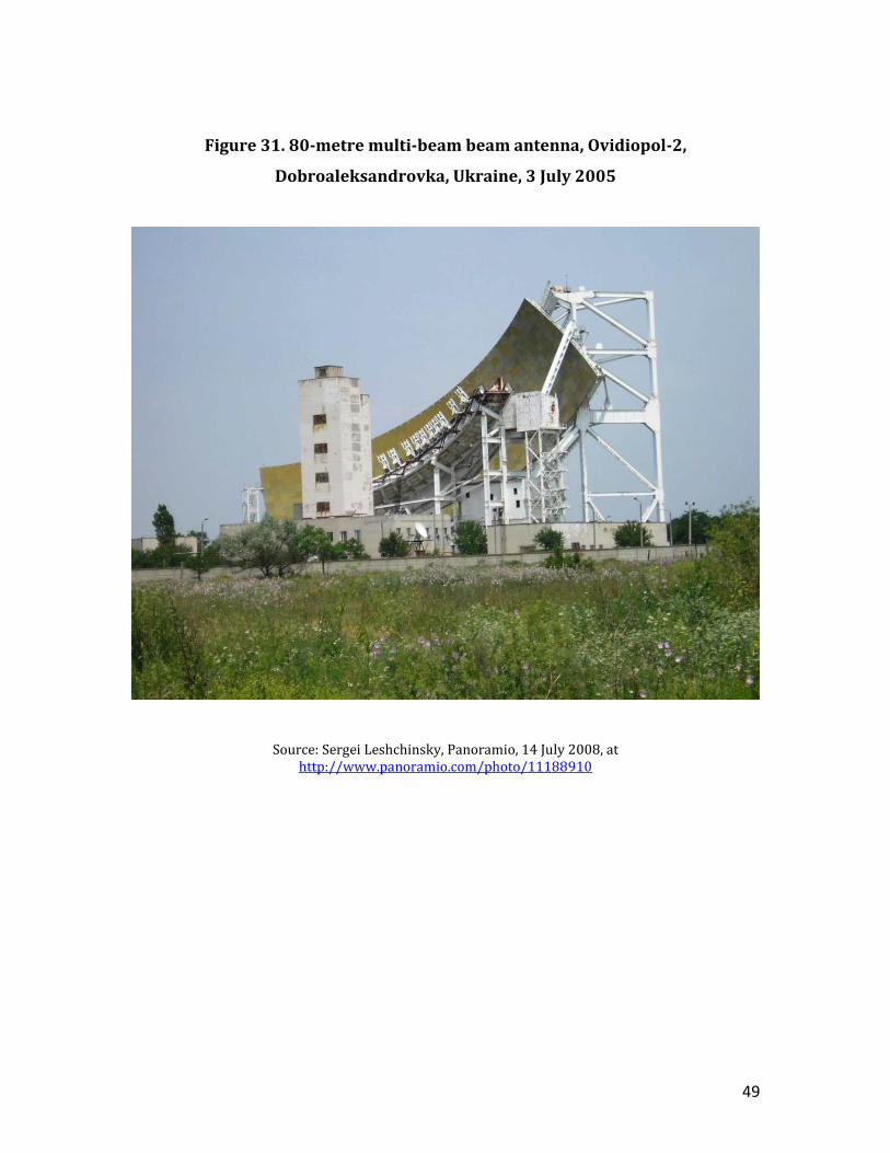
4.2 Ukrainian multi-beam system, Ovidiopol-2, Dobroaleksandrovka
Ukraine’s Foreign Intelligence Service (SZRU) maintains a COMSAT
interception station called Ovidiopol-2 near Dobroaleksandrovka in Ukraine which
has two multi-beam antennas, one of them of staggering dimensions. The station is
located about 4 km southwest of the town of Dobroaleksandrovka and 18 km
southwest of Odessa. It was established by the Soviet KGB’s 16th Directorate,
originally for HF radio interception, but began COMSAT interception activities in
1978. It was apparently taken over by Ukraine’s Security Service (SBU) after the
collapse of the Soviet Union in 1991, and then by the SZRU after its creation in
2005.53 There are now nine parabolic antennas at the station, most of which are
oriented to the southeast towards communications satellites stationed over the
Indian Ocean.54
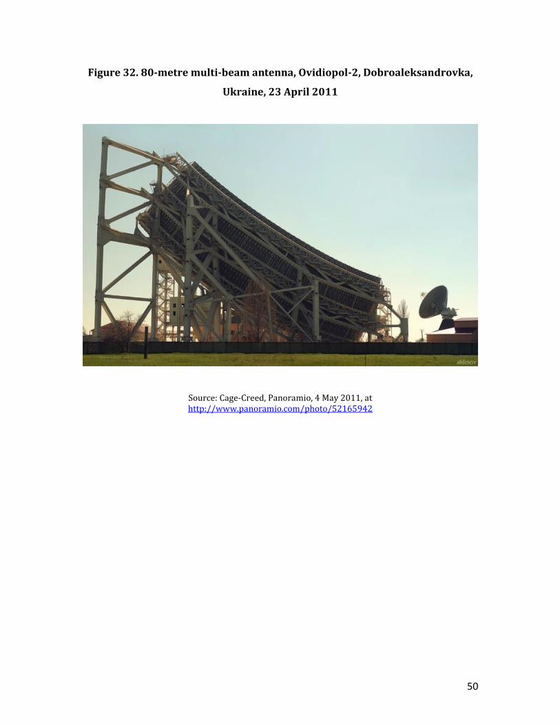
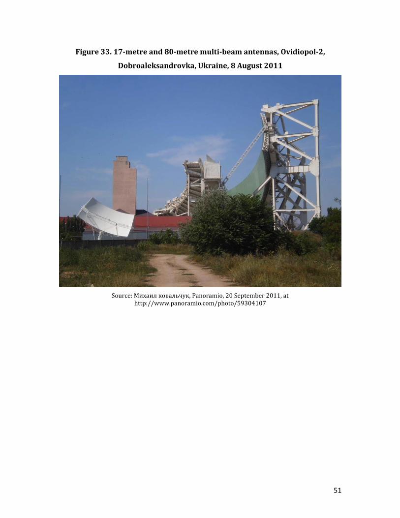
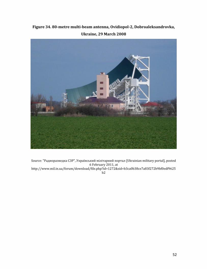
The very large multi-beam antenna is 80 metres wide, and points towards
the southwest, with an azimuth of about 220 degrees, corresponding to about 1
degree West longitude at the equator. The system is informally called the ‘Comb’. It
was evidently installed around 1987.55 (It was not there in 1983. The earliest Google
Earth image of the site is dated 29 September 2003, at which time it looked like it
had already been there for a long time). Photographs of the site on the Web show
that major renovations were undertaken between 2005 and 2008. The associated
Operations Building was renovated, the main reflector was re-painted, and the feeds
on rails on the feed-box may have been re-peaked. However, photographs taken in
2005, 2008 and 2011 show only 11-13 feeds on the feed-box, indicating that it was
monitoring 13 satellites simultaneously. (Figures 31-34)
The second, smaller multi-beam antenna, located in the southeast part of the
base, measures about 17 metres wide. Terraserver images show that it was installed
sometime between 24 July 2009 and 6 June 2010. It points to the southeast, with a
boresight around 150 degrees, corresponding to about 53 degrees East.
49
Figure 31. 80-metre multi-beam beam antenna, Ovidiopol-2,
Dobroaleksandrovka, Ukraine, 3 July 2005
Source: Sergei Leshchinsky, Panoramio, 14 July 2008, at http://www.panoramio.com/photo/11188910
50
Figure 32. 80-metre multi-beam antenna, Ovidiopol-2, Dobroaleksandrovka,
Ukraine, 23 April 2011
Source: Cage-Creed, Panoramio, 4 May 2011, at http://www.panoramio.com/photo/52165942
51
Figure 33. 17-metre and 80-metre multi-beam antennas, Ovidiopol-2,
Dobroaleksandrovka, Ukraine, 8 August 2011
Source: Михаил ковальчук, Panoramio, 20 September 2011, at http://www.panoramio.com/photo/59304107
52
Figure 34. 80-metre multi-beam antenna, Ovidiopol-2, Dobroaleksandrovka,
Ukraine, 29 March 2008
Source: "Радиоразведка СЗР", Український мілітарний портал [Ukrainian military portal], posted 6 February 2011, at
http://www.mil.in.ua/forum/download/file.php?id=1272&sid=b3ca0b38ce7a83f272b9bf0edf9625b2
53
5. Non-SIGINT U.S. military multi-beam antennas
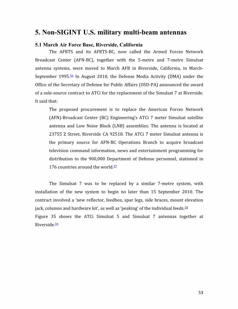
5.1 March Air Force Base, Riverside, California
The AFRTS and its AFRTS-BC, now called the Armed Forces Network
Broadcast Center (AFN-BC), together with the 5-metre and 7-metre Simulsat
antenna systems, were moved to March AFB in Riverside, California, in March-
September 1995.56 In August 2010, the Defense Media Activity (DMA) under the
Office of the Secretary of Defense for Public Affairs (OSD-PA) announced the award
of a sole-source contract to ATCi for the replacement of the Simulsat 7 at Riverside.
It said that:
The proposed procurement is to replace the American Forces Network
(AFN)-Broadcast Center (BC) Engineering’s ATCi 7 meter Simulsat satellite
antenna and Low Noise Block (LNB) assemblies. The antenna is located at
23755 Z Street, Riverside CA 92518. The ATCi 7 meter Simulsat antenna is
the primary source for AFN-BC Operations Branch to acquire broadcast
television command information, news and entertainment programming for
distribution to the 900,000 Department of Defense personnel, stationed in
176 countries around the world.57
The Simulsat 7 was to be replaced by a similar 7-metre system, with
installation of the new system to begin no later than 15 September 2010. The
contract involved a ‘new reflector, feedbox, spar legs, side braces, mount elevation
jack, columns and hardware kit’, as well as ‘peaking’ of the individual feeds.58
Figure 35 shows the ATCi Simulsat 5 and Simulsat 7 antennas together at
Riverside.59
54
Figure 35. ATCi Simulsat 5 and Simulsat 7 antennas, March AFB, Riverside,
California
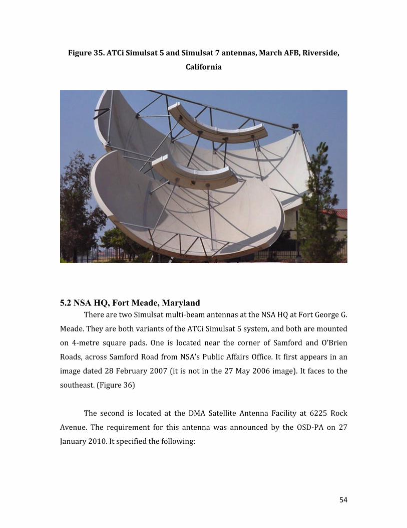
5.2 NSA HQ, Fort Meade, Maryland
There are two Simulsat multi-beam antennas at the NSA HQ at Fort George G.
Meade. They are both variants of the ATCi Simulsat 5 system, and both are mounted
on 4-metre square pads. One is located near the corner of Samford and O’Brien
Roads, across Samford Road from NSA’s Public Affairs Office. It first appears in an
image dated 28 February 2007 (it is not in the 27 May 2006 image). It faces to the
southeast. (Figure 36)
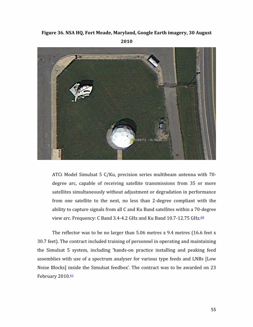
The second is located at the DMA Satellite Antenna Facility at 6225 Rock
Avenue. The requirement for this antenna was announced by the OSD-PA on 27
January 2010. It specified the following:
55
Figure 36. NSA HQ, Fort Meade, Maryland, Google Earth imagery, 30 August
2010
ATCi Model Simulsat 5 C/Ku, precision series multibeam antenna with 70-
degree arc, capable of receiving satellite transmissions from 35 or more
satellites simultaneously without adjustment or degradation in performance
from one satellite to the next, no less than 2-degree compliant with the
ability to capture signals from all C and Ku Band satellites within a 70-degree
view arc. Frequency: C Band 3.4-4.2 GHz and Ku Band 10.7-12.75 GHz.60
The reflector was to be no larger than 5.06 metres x 9.4 metres (16.6 feet x
30.7 feet). The contract included training of personnel in operating and maintaining
the Simulsat 5 system, including ‘hands-on practice installing and peaking feed
assemblies with use of a spectrum analyser for various type feeds and LNBs [Low
Noise Blocks] inside the Simulsat feedbox’. The contract was to be awarded on 23
February 2010.61
56
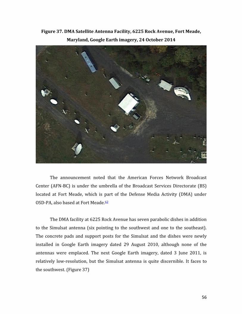
Figure 37. DMA Satellite Antenna Facility, 6225 Rock Avenue, Fort Meade,
Maryland, Google Earth imagery, 24 October 2014
The announcement noted that the American Forces Network Broadcast
Center (AFN-BC) is under the umbrella of the Broadcast Services Directorate (BS)
located at Fort Meade, which is part of the Defense Media Activity (DMA) under
OSD-PA, also based at Fort Meade.62
The DMA facility at 6225 Rock Avenue has seven parabolic dishes in addition
to the Simulsat antenna (six pointing to the southwest and one to the southeast).
The concrete pads and support posts for the Simulsat and the dishes were newly
installed in Google Earth imagery dated 29 August 2010, although none of the
antennas were emplaced. The next Google Earth imagery, dated 3 June 2011, is
relatively low-resolution, but the Simulsat antenna is quite discernible. It faces to
the southwest. (Figure 37)
57
The Simulsat 5 at the DMA facility provides ‘over 50 satellite feeds’.63
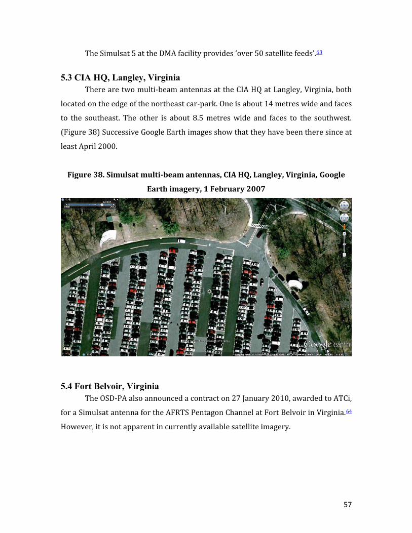
5.3 CIA HQ, Langley, Virginia
There are two multi-beam antennas at the CIA HQ at Langley, Virginia, both
located on the edge of the northeast car-park. One is about 14 metres wide and faces
to the southeast. The other is about 8.5 metres wide and faces to the southwest.
(Figure 38) Successive Google Earth images show that they have been there since at
least April 2000.
Figure 38. Simulsat multi-beam antennas, CIA HQ, Langley, Virginia, Google
Earth imagery, 1 February 2007
5.4 Fort Belvoir, Virginia
The OSD-PA also announced a contract on 27 January 2010, awarded to ATCi,
for a Simulsat antenna for the AFRTS Pentagon Channel at Fort Belvoir in Virginia.64
However, it is not apparent in currently available satellite imagery.
58
5.5 Naval Information Operations Command (NIOC), Suitland, Maryland
The Naval Information Operations Command (NIOC), located at 4251
Suitland Road in Suitland, Maryland, has a Simulsat 5 multi-beam antenna. It is
located in the southwest part of the NIOC compound, and faces to the southwest. It
is the largest variant of the Simulsat 5, with a width of 8.86 metres. Archival
sequences of Google Earth images show that it has been there since the early 1990s.
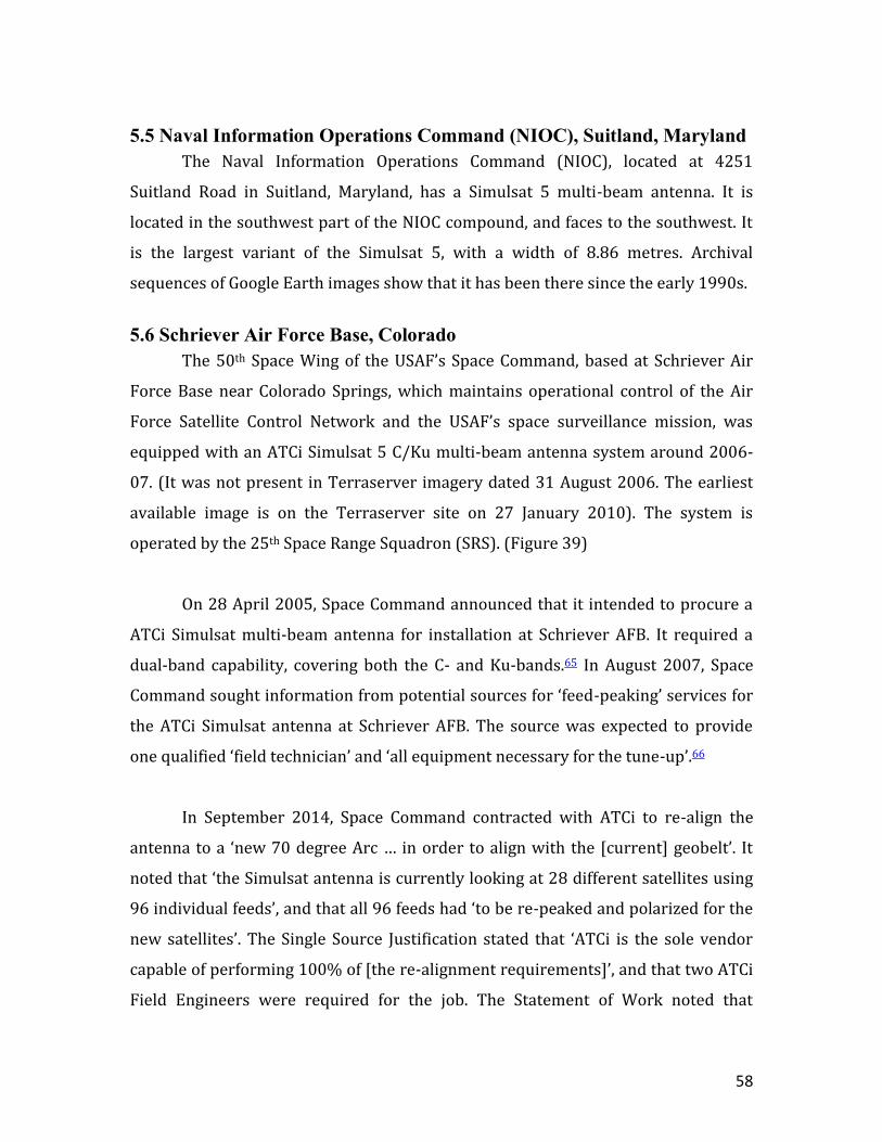
5.6 Schriever Air Force Base, Colorado
The 50th Space Wing of the USAF’s Space Command, based at Schriever Air
Force Base near Colorado Springs, which maintains operational control of the Air
Force Satellite Control Network and the USAF’s space surveillance mission, was
equipped with an ATCi Simulsat 5 C/Ku multi-beam antenna system around 2006-
07. (It was not present in Terraserver imagery dated 31 August 2006. The earliest
available image is on the Terraserver site on 27 January 2010). The system is
operated by the 25th Space Range Squadron (SRS). (Figure 39)
On 28 April 2005, Space Command announced that it intended to procure a
ATCi Simulsat multi-beam antenna for installation at Schriever AFB. It required a
dual-band capability, covering both the C- and Ku-bands.65 In August 2007, Space
Command sought information from potential sources for ‘feed-peaking’ services for
the ATCi Simulsat antenna at Schriever AFB. The source was expected to provide
one qualified ‘field technician’ and ‘all equipment necessary for the tune-up’.66
In September 2014, Space Command contracted with ATCi to re-align the
antenna to a ‘new 70 degree Arc … in order to align with the [current] geobelt’. It
noted that ‘the Simulsat antenna is currently looking at 28 different satellites using
96 individual feeds’, and that all 96 feeds had ‘to be re-peaked and polarized for the
new satellites’. The Single Source Justification stated that ‘ATCi is the sole vendor
capable of performing 100% of [the re-alignment requirements]’, and that two ATCi
Field Engineers were required for the job. The Statement of Work noted that
59
repositioning of the Simulsat ‘will cause the antenna structure to sit slightly off the
current concrete pad’, and hence ‘concrete additions’ were required. It also stated
that Space Command ‘will furnish a listing of satellites which the feeds will be
peaked upon’, as well as ‘provide [the] contractor with new antenna look angle’.67
The Simulsat antenna at Schriever is 9.5 metres wide, the standard size of the ATCi
Simulsat 5B system. It is located at 38.8006 North, 104.522 West, in the southeast
part of the base, 25th Space Range Squadron's Advanced Capabilities Environment
laboratory.68 It is oriented towards the south.
Figure 39. Simulsat antenna, Schriever Air Force Base, Google Map imagery
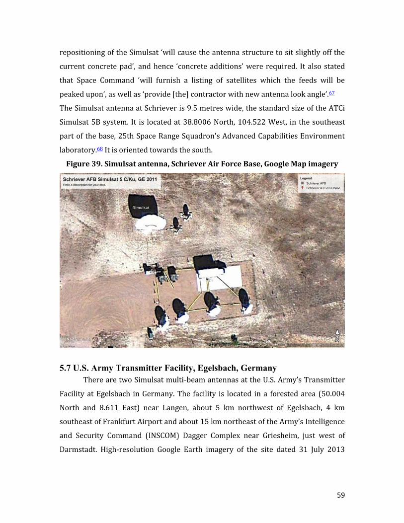
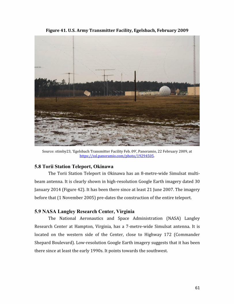
5.7 U.S. Army Transmitter Facility, Egelsbach, Germany
There are two Simulsat multi-beam antennas at the U.S. Army’s Transmitter
Facility at Egelsbach in Germany. The facility is located in a forested area (50.004
North and 8.611 East) near Langen, about 5 km northwest of Egelsbach, 4 km
southeast of Frankfurt Airport and about 15 km northeast of the Army’s Intelligence
and Security Command (INSCOM) Dagger Complex near Griesheim, just west of
Darmstadt. High-resolution Google Earth imagery of the site dated 31 July 2013
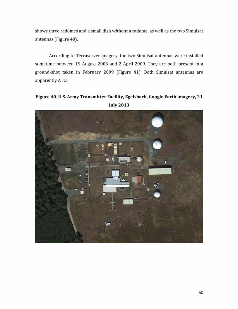
60
shows three radomes and a small dish without a radome, as well as the two Simulsat
antennas (Figure 40).
According to Terraserver imagery, the two Simulsat antennas were installed
sometime between 19 August 2006 and 2 April 2009. They are both present in a
ground-shot taken in February 2009 (Figure 41). Both Simulsat antennas are
apparently ATCi.
Figure 40. U.S. Army Transmitter Facility, Egelsbach, Google Earth imagery, 21
July 2013
61
Figure 41. U.S. Army Transmitter Facility, Egelsbach, February 2009
Source: stimby23, ‘Egelsbach Transmitter Facility Feb. 09’, Panoramio, 22 February 2009, at https://ssl.panoramio.com/photo/19294505.
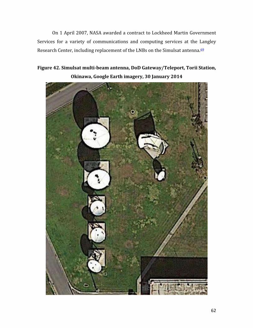
5.8 Torii Station Teleport, Okinawa
The Torii Station Teleport in Okinawa has an 8-metre-wide Simulsat multi-
beam antenna. It is clearly shown in high-resolution Google Earth imagery dated 30
January 2014 (Figure 42). It has been there since at least 21 June 2007. The imagery
before that (1 November 2005) pre-dates the construction of the entire teleport.
5.9 NASA Langley Research Center, Virginia
The National Aeronautics and Space Administration (NASA) Langley
Research Center at Hampton, Virginia, has a 7-metre-wide Simulsat antenna. It is
located on the western side of the Center, close to Highway 172 (Commander
Shepard Boulevard). Low-resolution Google Earth imagery suggests that it has been
there since at least the early 1990s. It points towards the southwest.
62
On 1 April 2007, NASA awarded a contract to Lockheed Martin Government
Services for a variety of communications and computing services at the Langley
Research Center, including replacement of the LNBs on the Simulsat antenna.69
Figure 42. Simulsat multi-beam antenna, DoD Gateway/Teleport, Torii Station,
Okinawa, Google Earth imagery, 30 January 2014
63
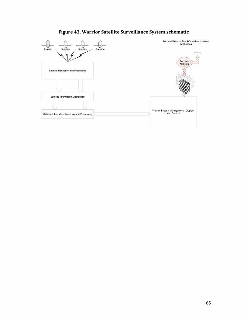
5.10 ATCi Warrior Satellite Surveillance System
In January 2008, ATCi announced that it had developed the Warrior Satellite
Surveillance System for simultaneously monitoring satellites across the
geostationary belt, designed specifically ‘for the unique requirements of government
and military entities’. (Figure 43) In May of that year, ATCi’s CEO, Gary Hatch, stated
that ‘Warrior’s core technology is an already proven and delivered solution that is
key to many large Department of Defense Systems as well as other government,
military and multimedia systems in operation today’. He also noted that the
company ‘has a long standing history in successfully implementing sensitive
surveillance and monitoring systems for the Department of Defense and other like
government and military agencies in the US’.70
In addition to its standard Simulsat capabilities for simultaneously
monitoring RF [radio frequency] transmissions from multiple geostationary
satellites, the Warrior system is able ‘to automatically analyse, manage, control, and
archive the content being carried on any given transponder on any given satellite in
its viewing arc’. Moreover, the Warrior system uses two Simulsat antennas with
azimuths angled 70 degrees apart to monitor the signals of 70 or more satellites
over an arc of 140 degrees. It is able to ‘simultaneously process thousands of RF
carriers’ in the X-band, C-band, Ka-band and Ku-band. It can be networked with
other stations to provide complete global coverage. A ‘full satellite arc RF jamming’
capability can also be provided. Mobile systems are also available.71
The Warrior system incorporates a new ARC (Archive/Retrieval/Catalogue)
Sentry feature, which displays the status of the satellites being monitored and can
automatically trigger various alarms. According to ATCi, the advanced system
‘enables planned and non-planned event analysis of activities transpiring over any
of the satellites simultaneously within the 140 degree view arc’. It says that the
‘proprietary search and retrieve technology loads key information METADATA into
64
an interlinked network of IP storage servers to provide unparalleled surveillance
tools for today’s fluid and ever-changing communication markets’. The system
enables ‘geo-location and tracking of rogue RF [carriers]’ as well as ‘voice/data
interdiction’ and storage of the metadata ‘over many years’.72
The ATCi CEO, Gary Hatch, an enthusiastic advocate of multi-beam
technology, has said that ‘monitoring virtually everything in the sky has become
critical in today’s digital world’, and that:
It is not enough to simply monitor FSS [Fixed-Satellite Service] satellites;
today’s skyway and highway surveillance must also have the ability to
associate and provide critical algorithms and patterning data. [The Warrior
system] can ultimately process and index massive IP data troves thereby
delivering greater relational data pattern information to make the best
rational decisions [and provide] much greater security.73
In November 2008, ATCi announced that its Warrior system had been
deployed in ‘the Asian region’. It stated that ‘several’ Warrior-like systems were
employed in ‘Asian defense networks’, but it did not identify the country or
countries involved.74 In January 2009, the Indian government announced that it had
procured the Warrior system to cover the sub-continent region. Hatch said that
following the terrorist attacks in Mumbai in November 2008, India had ‘a
heightened requisite for extensive monitoring and surveillance of everything in the
sky’.75
65
Figure 43. Warrior Satellite Surveillance System schematic
66
Annexe 1: Analysis of satellite terminals at Five Eyes FORNSAT/COMSAT sites,
2000–2015
Site Covername Notes Survey period 1: 1995-2004
Trad COTS Survey period 2: 2003-2010
Trad COTS Survey period
3: 2011 to present
Trad COTS Torus
Ayios Nikolaos
SOUNDER -
1x33m, 1x18m, 2x12m, 3x8m, 1x6mr, 1x4m
[2003]
8 1
1x33m, 3x18m, 2x12m, 3x8m, 1x6mr, 2x5m, 1x4m [2008]
10 3
1x33m, 3x18m, 2x12m, 3x8m, 1x6mr, 2x5m, 7x4m, 2x3m,
6x2.5m?, Torus [2015]
10 17 1
Bad Aibling GARLICK
Transfer-red to BND
2004; not counted
after 2004
1x30mr, 1x27mr, 1x21mr, 1x18mr, 4x16mr, 1x13mr, 4x12mr, 4x10mr,
2x9.5mr, 1x7mr, 1x5m [2002]
20 1
1x30mr, 1x27mr, 1x18mr, 4x16mr, 1x13mr, 1x12mr
[2009]
(9) (0)
1x30mr, 1x27mr, 1x18mr, 4x16mr, 1x13mr,
1x12mr, 1x8m [2012]
(10) (0) (0)
Bude CARBOY -
3x33m, 1x30mr, 3x19.5m,
3x14m, 2x13mr, 4x12m, 1x7.5m,
2x4m [2001]
17 2
3x33m, 1x30mr, 3x19.5m, 3x14m, 2x13mr, 4x12m, 1x7.5m, 1x5m, 2x4m, 3x2m?
[2005]
17 6
3x33m, 1x30mr, 3x19.5m,
3x14m, 1x13mr, 4x12m, 1x9.5m, 1x7.5m, 2x4m, 1x2m?, Torus
[2013 ]
17 3 1
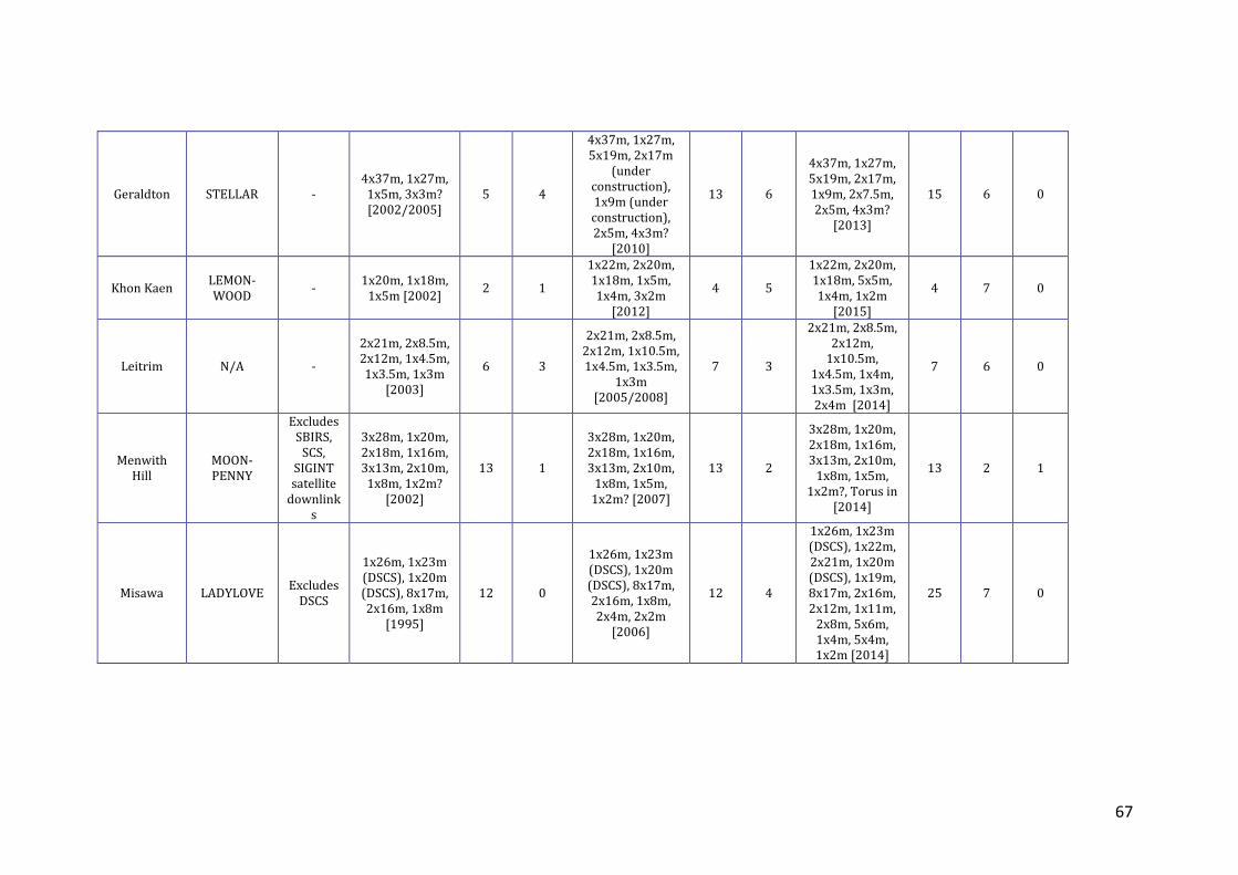
67
Geraldton STELLAR - 4x37m, 1x27m,
1x5m, 3x3m? [2002/2005]
5 4
4x37m, 1x27m, 5x19m, 2x17m
(under construction), 1x9m (under construction), 2x5m, 4x3m?
[2010]
13 6
4x37m, 1x27m, 5x19m, 2x17m, 1x9m, 2x7.5m, 2x5m, 4x3m?
[2013]
15 6 0
Khon Kaen LEMON-WOOD
- 1x20m, 1x18m,
1x5m [2002] 2 1
1x22m, 2x20m, 1x18m, 1x5m, 1x4m, 3x2m
[2012]
4 5
1x22m, 2x20m, 1x18m, 5x5m, 1x4m, 1x2m
[2015]
4 7 0
Leitrim N/A -
2x21m, 2x8.5m, 2x12m, 1x4.5m, 1x3.5m, 1x3m
[2003]
6 3
2x21m, 2x8.5m, 2x12m, 1x10.5m, 1x4.5m, 1x3.5m,
1x3m [2005/2008]
7 3
2x21m, 2x8.5m, 2x12m,
1x10.5m, 1x4.5m, 1x4m, 1x3.5m, 1x3m, 2x4m [2014]
7 6 0
Menwith Hill
MOON-PENNY
Excludes SBIRS,
SCS, SIGINT satellite
downlinks
3x28m, 1x20m, 2x18m, 1x16m, 3x13m, 2x10m,
1x8m, 1x2m? [2002]
13 1
3x28m, 1x20m, 2x18m, 1x16m, 3x13m, 2x10m,
1x8m, 1x5m, 1x2m? [2007]
13 2
3x28m, 1x20m, 2x18m, 1x16m, 3x13m, 2x10m,
1x8m, 1x5m, 1x2m?, Torus in
[2014]
13 2 1
Misawa LADYLOVE Excludes
DSCS
1x26m, 1x23m (DSCS), 1x20m (DSCS), 8x17m, 2x16m, 1x8m
[1995]
12 0
1x26m, 1x23m (DSCS), 1x20m (DSCS), 8x17m, 2x16m, 1x8m, 2x4m, 2x2m
[2006]
12 4
1x26m, 1x23m (DSCS), 1x22m, 2x21m, 1x20m (DSCS), 1x19m, 8x17m, 2x16m, 2x12m, 1x11m,
2x8m, 5x6m, 1x4m, 5x4m, 1x2m [2014]
25 7 0
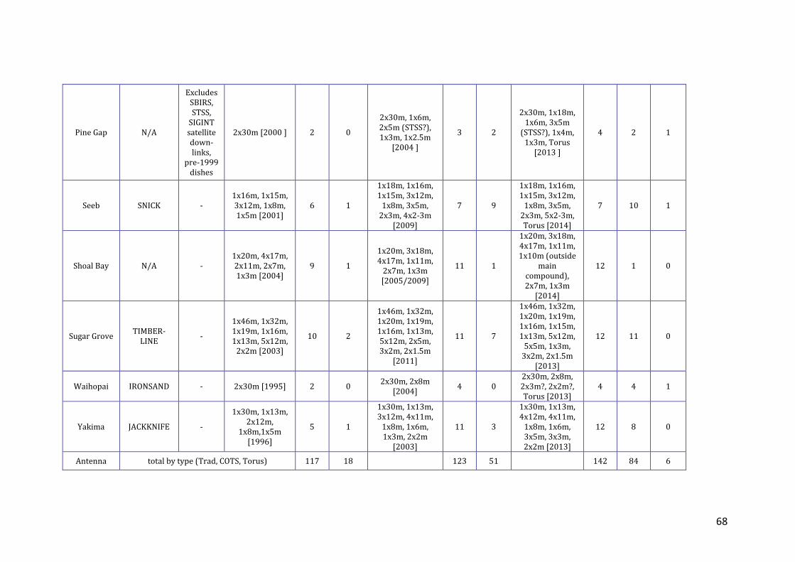
68
Pine Gap N/A
Excludes SBIRS, STSS,
SIGINT satellite down-links,
pre-1999 dishes
2x30m [2000 ] 2 0
2x30m, 1x6m, 2x5m (STSS?), 1x3m, 1x2.5m
[2004 ]
3 2
2x30m, 1x18m, 1x6m, 3x5m
(STSS?), 1x4m, 1x3m, Torus
[2013 ]
4 2 1
Seeb SNICK - 1x16m, 1x15m, 3x12m, 1x8m, 1x5m [2001]
6 1
1x18m, 1x16m, 1x15m, 3x12m,
1x8m, 3x5m, 2x3m, 4x2-3m
[2009]
7 9
1x18m, 1x16m, 1x15m, 3x12m,
1x8m, 3x5m, 2x3m, 5x2-3m, Torus [2014]
7 10 1
Shoal Bay N/A - 1x20m, 4x17m, 2x11m, 2x7m, 1x3m [2004]
9 1
1x20m, 3x18m, 4x17m, 1x11m,
2x7m, 1x3m [2005/2009]
11 1
1x20m, 3x18m, 4x17m, 1x11m, 1x10m (outside
main compound), 2x7m, 1x3m
[2014]
12 1 0
Sugar Grove TIMBER-
LINE -
1x46m, 1x32m, 1x19m, 1x16m, 1x13m, 5x12m,
2x2m [2003]
10 2
1x46m, 1x32m, 1x20m, 1x19m, 1x16m, 1x13m, 5x12m, 2x5m, 3x2m, 2x1.5m
[2011]
11 7
1x46m, 1x32m, 1x20m, 1x19m, 1x16m, 1x15m, 1x13m, 5x12m,
5x5m, 1x3m, 3x2m, 2x1.5m
[2013]
12 11 0
Waihopai IRONSAND - 2x30m [1995] 2 0 2x30m, 2x8m
[2004] 4 0
2x30m, 2x8m, 2x3m?, 2x2m?, Torus [2013]
4 4 1
Yakima JACKKNIFE -
1x30m, 1x13m, 2x12m,
1x8m,1x5m [1996]
5 1
1x30m, 1x13m, 3x12m, 4x11m,
1x8m, 1x6m, 1x3m, 2x2m
[2003]
11 3
1x30m, 1x13m, 4x12m, 4x11m,
1x8m, 1x6m, 3x5m, 3x3m, 2x2m [2013]
12 8 0
Antenna total by type (Trad, COTS, Torus) 117 18 123 51 142 84 6
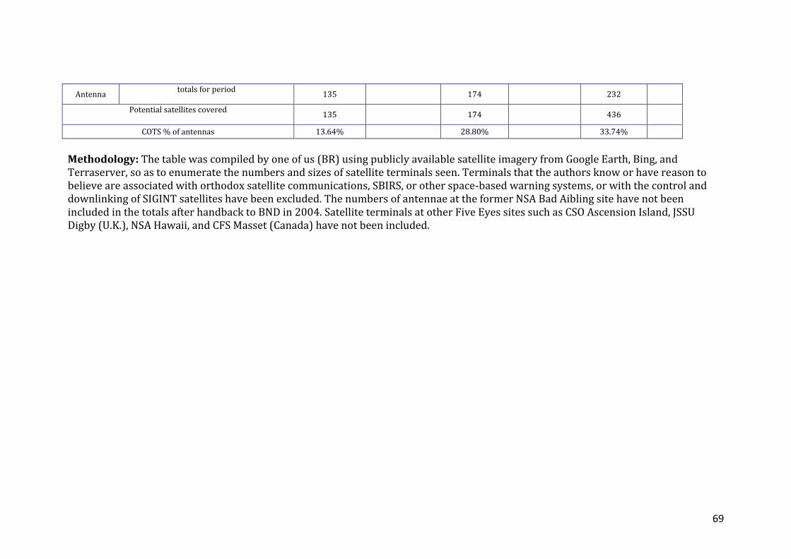
69
Antenna totals for period
135 174 232
Potential satellites covered
135 174 436
COTS % of antennas 13.64% 28.80% 33.74%
Methodology: The table was compiled by one of us (BR) using publicly available satellite imagery from Google Earth, Bing, and Terraserver, so as to enumerate the numbers and sizes of satellite terminals seen. Terminals that the authors know or have reason to believe are associated with orthodox satellite communications, SBIRS, or other space-based warning systems, or with the control and downlinking of SIGINT satellites have been excluded. The numbers of antennae at the former NSA Bad Aibling site have not been included in the totals after handback to BND in 2004. Satellite terminals at other Five Eyes sites such as CSO Ascension Island, JSSU Digby (U.K.), NSA Hawaii, and CFS Masset (Canada) have not been included.
70
References 1 The terms FORNSAT and COMSAT have the same meaning in this report, but are used to reflect different usage as between NSA (FORNSAT) and its Second Party partners (COMSAT). 2 Building on WW2 signals intelligence cooperation arrangements, the UKUSA agreements negotiated from 1940 to 1955 between the principal signals intelligence agencies of the United States and the United Kingdom, and subsequently with those of Australia, Canada, and New Zealand, form the basis for what Richelson and Ball described as ‘a truly multinational community’. The term ‘Five Eyes’ (FVEY) is now generally used in SIGINT documents seen in the Snowden disclosures in place of the former term UKUSA, but also applies to a wider range of US-auspiced military and intelligence cooperation arrangements between the partner countries. See Jeffrey T. Richelson and Desmond Ball, The Ties That Bind: Intelligence Cooperation Between the UKUSA Countries - the United Kingdom, the United States of America, Canada, Australia and New Zealand, Sydney, London and Boston: George Allen and Unwin, 1985; Jeffrey T. Richelson, The US Intelligence Community, sixth edition, Westview, 2011, pp. 292-296; and similar in other editions; UKUSA Agreement Release 1940-1956, National Security Agency, 24 June 2010, at https://www.nsa.gov/public_info/declass/ukusa.shtml; and Richard Tanter, The ‘Joint Facilities’ revisited – Desmond Ball, democratic debate on security, and the human interest, Special Report, Nautilus Institute for Security and Sustainability, 12 December 2012, at http://nautilus.org/wp-content/uploads/2012/12/The-_Joint-Facilities_-revisited-1000-8-December-2012-2.pdf. 3 Glenn Greenwald, No Place to Hide: Edward Snowden, the NSA, and the U.S Surveillance State, (Metropolitan Books, New York, 2014), p. 97; and Glenn Greenwald, ‘Documents from No Place to Hide’, at http://glenngreenwald.net/pdf/NoPlaceToHide-Documents-Compressed.pdf. 4 ‘GCSB Update 22 April 2010’, at http://cryptome.org/2015/03/gcsb-xkeyscore-nz-star-times-15-0308.pdf; Nicky Hager and Ryan Gallagher, ‘Snowden Revelations. The Price of the Five Eyes Club: Mass Spying on Friendly Nations’, The New Zealand Herald, 5 March 2015, at http://www.nzherald.co.nz/nz/news/article.cfm?c_id=1&objectid=11411759. 5 Massive Volume Reduction is a SIGINT technique for sifting the entirety of large communications channels while the data is being held in a large temporary storage cache, typically for three days. 6 See Figure 1. 7 The meaning of the coverterm TARMAC has not been disclosed in published Snowden documents but appears to refer to improved technology, expanded collection, and better target development as indicated in Figure 3. 8 ‘GCSB Update 22 April 2010’, op.cit. 9 Ibid. 10 ‘Footprints’, Satbeams, at http://www.satbeams.com/footprints. 11 Duncan Campbell, Interception Capabilities 2000, Report to the Director General for Research of the European Parliament (Scientific and Technical Options Assessment programme office), April, 1999, at http://www.duncancampbell.org/menu/surveillance/echelon/IC2000_Report%20.pdf. 12 For a notable exception, see 'Torus: the antenna to significantly increase satellite interception', Top Level Communications, 8 April 2015, at http://electrospaces.blogspot.ca/2015/04/torus-antenna-to-significantly-increase.html.

71
13 Identified in multiple career resumes and recruitment listings for or by SIGINT staff. 14 'Spying Close to Home: German Intelligence Under Fire for NSA Cooperation', Spiegel Online International, 24 April 2015, at http://www.spiegel.de/international/germany/german-intelligence-agency-bnd-under-fire-for-nsa-cooperation-a-1030593.html; and 'Berlin deleted '12,000 NSA spy requests', The Local (de), 1 May 2015, at http://www.thelocal.de/20150501/berlin-deleted-12000-nsa-spying-requests-report. 15 'Old Soviet Listening Posts', Google Maps, at https://www.google.com/maps/d/viewer?mid=zp2K5WStbci8.kRGSb08LIoys&msa=0. 16 Matthew Aid, 'Chinese SIGINT Sites', Matthew Aid.com, 4 June 2012, at http://www.matthewaid.com/post/24424601613/chinese-sigint-sites. 17 Report by Duncan Campbell for the Wired magazine, forthcoming at the time of this publication. 18 Campbell, Interception Capabilities 2000, op.cit. 19 Duncan Campbell, ‘Revealed: GCHQ’s Beyond Top Secret Middle Eastern Internet Spy Base’, The Register, 3 June 2014, at http://www.theregister.co.uk/2014/06/03/revealed_beyond_top_secret_british_intelligence_middleeast_internet_spy_base. 20 'GCHQ Seeb Submarine Cables Interception Base', Cryptome, 8 June 2014, at http://cryptome.org/2014-info/gchq-seeb/gchq-seeb.htm. 21 Published later by Der Spiegel magazine in a different typeface. 22 See Bill Robinson, 'CAC-98CG monitors Internet and/or IM traffic', 15 October 2013, at http://luxexumbra.blogspot.ca/2013/10/cac-98cg-monitors-internet-andor-im.html 23 General Dynamics, ‘Model 700-70TCK Torus Multiple Band Antenna’, at http://www.gdsatcom.com/Antennas/Data_Sheets/655-0037C_7M_Torus.pdf. 24 Nicky Hager, Secret Power: New Zealand’s Role in the International Spy Network, (Craig Potton, Nelson, 1996), p.33. 25 ‘“Poodle” UK: MPs to Quiz GCHQ Spies Over $150Mln Payments from US Government’, 3 August 2013, at http://rt.com/news/nsa-gchq-mps-questions-007/; and ‘Die Überwacher überwachen beim GCHQ Bude’, Youtube, uploaded 15 November 2013, at https://www.youtube.com/watch?v=gKImRK_BPAg. 26 Richard Norton-Taylor, ‘Menwith Hill Eavesdropping Base Undergoes Massive Expansion’, The Guardian, 2 March 2012, at http://www.theguardian.com/world/2012/mar/01/menwith-hill-eavesdropping-base-expansion. 27 Campaign for the Accountability of American Bases, ‘Planning Applications’, at http://www.caab.org.uk/the-american-bases/planning-applications. 28 Nicky Hager and Stefania Maurizi, ‘Cyprus: the home of British/American Internet surveillance in the Middle East', L'Espresso, 5 November 2013, at http://espresso.repubblica.it/inchieste/2013/11/04/news/the-history-of-british-intelligence-operations-in-cyprus-1.139978.
72
29 Des Ball, Pine Gap: Australia and the US Geostationary Signals Intelligence Satellite Program, (Allen & Unwin, Sydney, 1988); Desmond Ball, ‘Foreword’, in Leonce Kealy, The Pine Gap Saga: Personal Experience Working with the American CIA in Australia, (2008); and David Rosenberg, Inside Pine Gap: The Spy Who Came in from the Desert, (Hardie Grant Books, Melbourne, 2011). 30 Richard Tanter, Bill Robinson and Desmond Ball, ‘Recent Developments at the Joint Defence Facility Pine Gap’, Nautilus Institute, Special Report, forthcoming. 31 Jeffrey T. Richelson, The US Intelligence Community, (Westview Press, Boulder, Colorado, Sixth edition, 2012), pp. 223-224. 32 Jeff Ford, LinkedIn, at https://www.linkedin.com/in/jeffreyford97. 33 Robert Donaldson, LinkedIn, at https://www.linkedin.com/pub/robert-donaldson/91/57b/2b8. 34 ‘25 Air Force Organization Chart’, 29 September 2014, copy provided by Jeffrey Richelson. 35 Nicky Hager, Secret Power: New Zealand’s Role in the International Spy Network, (Craig Potton, Nelson, 1996), pp. 26-28. 36 ‘GCSB Update 21 March 2012’, Cryptome, at http://cryptome.org/2015/03/gcsb-xkeyscore-nz-star-times-15-0308.pdf. 37 Nicky Hager, 'What does Waihopai spy on?’Peace Researcher, 40, July 2010 at http://www.converge.org.nz/abc/pr40-195.htm. 38 ‘New Dish Joins Golf Balls at Spy Base’, Marlborough Express, ca June 2007, at http://www.apsattv.com/history/july200710th-16th.html. 39 ‘Spybase Attack’, Free to Air Satellite Forums, 3 and 4 May 2008, at http://www.vetrun.net/forums/showthread.php?t=8403. 40 ‘For the satellites that are reflected by the edges of the reflector, there is some spill-over and there is also more ground noise that the feeds are exposed to. However, the overall effect of this is minor and we have not seen a discernible difference in performance between edge feeds and middle feeds.’ Simulsat Explained - Frequently Asked Questions, ATCi, at http://www.atci.com/assets/simulsat-faq.pdf. 41 Simulsat Multibeam Earth Station Product Family, (ATCi, 2012), at http://www.atci.com/assets/simulsat_brochure2012.pdf. The CEO of ATCi boasted that ‘the ability to enable surveillance of 70 satellites simultaneously on approximately two parking spaces has created an incredible tool for the U.S. Department of Defense and other like agencies worldwide’. Spotlight interview with Gary Hatch, ATCi CEO, at http://www.atci.com/assets/spotlight-interview.pdf. 42 Eric Johnston, ‘List of Satellites in Geostationary Orbit’, 11 November 2014, at http://www.satsig.net/sslist.htm; and ‘How Closely Spaced Are Satellites at GEO?’, 24 October 2013, at http://space.stackexchange.com/questions/2515/how-closely-spaced-are-satellites-at-geo. 43 ATCi, Simulsat Operation and Maintenance Manual, (ATCi, Chandler, Arizona, 16 March 2000), p. 3. 44 Ibid, pp. 4-6. 45 ‘Satellite Station Does the Job of Three’, New Scientist, 26 July 1979, p. 291.

73
46 COMSAT Laboratories, ‘Final Report on Multiple Beam Torus Antenna Study Prepared for Defense Communications Agency: Volume 1’, March 1977, at http://www.dtic.mil/dtic/tr/fulltext/u2/a047157.pdf; and COMSAT Laboratories, ‘Final Report on Multiple Beam Torus Antenna Study Prepared for Defense Communications Agency: Volume II’, March 1977, at http://www.dtic.mil/dtic/tr/fulltext/u2/a047158.pdf. 47 Marvin D. Shoemake, ‘The Torus Antenna’, NCTA Technical Papers 1982, at http://www.nctatechnicalpapers.com/Paper/1982/1982-the-torus-antenna. 48 ‘Radiation Systems Manufacturing, Selling Torus Antennas’, COMSAT: Communications Satellite Corporation Magazine, (No. 3, 1981), p. 3, at http://www.comara.org/legacy/comsat_magazine/COMSAT_Magazine_3.pdf. 49 Simulsat Multibeam Earth Station Product Family, (ATCi, 2012), at http://www.atci.com/assets/simulsat_brochure2012.pdf. 50 L. Blaisdell, S. Carrillo and H. Gelman, ‘RF Design and Performance of a Multibeam, Multiband Antenna’, RADC Proceedings of the Antenna Applications Symposium, March 1984, Vol. 2, pp. 239-263, at http://adsabs.harvard.edu/abs/1984anap....2..239B. 51 ‘Environmental Impact Analysis Process: Final Environmental Assessment, Armed Forces Radio and Television Service – Broadcast Center, Move to March AFB, California’, (Department of the Air Force, February 1995), at http://www.dtic.mil/dtic/tr/fulltext/u2/a413221.pdf. 52 Ibid. 53 ‘Veterans of KGB Signals Intelligence – Unite!’, at http://www.mil.in.ua/forum/viewtopic.php?f=83&t=764. 54 Matthew Aid, ‘Most Soviet-Era KGB Listening Posts Still Operating and Listening to the West’, 2 July 2013, at http://www.matthewaid.com/post/54433673869/most-soviet-era-kgb-listening-posts-still. 55 ‘Comments’, at https://ssl.panoramio.com/photo/11188910#c33751879. 56 ‘Environmental Impact Analysis Process: Final Environmental Assessment, Armed Forces Radio and Television Service – Broadcast Center, Move to March AFB, California’, (Department of the Air Force, February 1995), at http://www.dtic.mil/dtic/tr/fulltext/u2/a413221.pdf. 57 ‘Simulsat 7 Meter Antenna’, FedBizOps (Federal Business Opportunities), 5 August 2010, at https://www.fbo.gov/?s=opportunity&mode=form&id=21c26918a63984b837b8ed4b18469bb0&tab=core&_cview=0. 58 Ibid. 59 ‘ATCi Simulsat Projects’, at http://www.atci.com/images/ca_riverside_ss5n7.jpg. 60 ‘Simulsat Antenna System’, FedBizOps (Federal Business Opportunities), 27 January 2010, at https://www.fbo.gov/?s=opportunity&mode=form&id=5cbe9d0e11b2a303c5535db658dfb351&tab=core&_cview=1. 61 Ibid. 62 Ibid. 63 Bill Dingman, LinkedIn, at https://www.linkedin.com/pub/bill-dingman/54/88a/799.

74
64 ‘Simulsat Antenna System’, 27 January 2010, op.cit. 65 ‘Satellite Earth Station Antenna’, FedBizOps (Federal Business Opportunities), 28 April 2005, at https://www.fbo.gov/index?s=opportunity&mode=form&id=518020799a27c91e4179ce447a558c08&tab=core&_cview=0. 66 Department of the Air Force, ‘Sources Sought for Simulsat Tuning’, FedBizOps (Federal Business Opportunities), 10 August 2007, at https://www.fbo.gov/index?s=opportunity&mode=form&id=e291d81608da532162dacc1dd74a2b3d&tab=core&_cview=1. 67 ‘Single Source Justification (Simplified Acquisition): Simulsat Antenna Re-alignment’, FedBizOps (Federal Business Opportunities), 17 September 2014, at https://www.fbo.gov/index?s=opportunity&mode=form&id=d586c59f7cdeb2f423e78d462227de8b&tab=core&_cview=1. 68 Stacy Foster, “AFSPC Commander Visits 'Masters Of Space'”, 50th Space Wing Public Affairs, Schriever AFB CO (AFNS), Space War, 2 November 2009, at http://www.spacewar.com/reports/AFSPC_Commander_Visits_Masters_Of_Space_999.html. 69 NASA Langley Research Center, ‘Solicitation/Contract/Order for Commercial Items’, 1 April 2007, at http://www.nasa.gov/sites/default/files/files/contract-nnl07aa69d.pdf. 70 ACTi Corporate Office, ‘ATCi Introduces Warrior Satellite Monitoring System’, Press Release, 8 January 2008, at http://www.atci.com/assets/warrior.pdf; ‘ACTi Introduces New Features to Its Warrior Satellite Surveillance System’, PR Newswire, 20 May 2008, at http://www.prnewswire.com/news-releases/atci-introduces-new-features-to-its-warrior-satellite-surveillance-system-57268847.html; and ‘ATCi’s Warrior Satellite Surveillance and Monitoring System’, Space Daily, 7 July 2009, at http://www.spacedaily.com/reports/ATCi_Warrior_Satellite_Surveillance_And_Monitoring_System_999.html. 71 ACTi Corporate Office, ‘ATCi Introduces Warrior Satellite Monitoring System’, op. cit.; ‘ACTi Introduces New Features to Its Warrior Satellite Surveillance System’, op.cit. 72 ‘ACTi Introduces New Features to Its Warrior Satellite Surveillance System’, op. cit.; ‘ATCi’s Warrior Satellite Surveillance and Monitoring Systems Deployed to Foreign Asian Defense Networks’, PR Newswire, 19 November 2008, at http://www.prnewswire.com/news-releases/atcis-warrior-satellite-surveillance-and-monitoring-systems-deployed-to-foreign-asian-defense-networks-65482307.html; and ‘ATCi to Host Industry’s First Satellite Surveillance and Monitoring Workshop’, 18 September 2008, at http://www.businesswire.com/news/home/20080918005328/en/ATCi-Host-Industrys-Satellite-Surveillance-Monitoring-Workshop#.VSXLhvAf7vA. 73 ACTi Corporate Office, ‘ATCi Introduces Warrior Satellite Monitoring System’, op. cit; ‘ATCi’s Warrior Satellite Surveillance and Monitoring Systems Deployed to Foreign Asian Defense Networks’, op.cit.; and ‘Warrior Satellite Monitoring and Surveillance System Manifests Quantum Certification’, PR Newswire, 26 February 2014, at http://www.prnewswire.com/news-releases/warrior-satellite-monitoring-and-surveillance-system-manifests-quantum-certification-247300611.html. 74 ‘ATCi’s Warrior Satellite Surveillance and Monitoring Systems Deployed to Foreign Asian Defense Networks’, op.cit. 75 ‘India Embraces ATCi’s Warrior Satellite Surveillance and Monitoring Systems Deployed for Foreign Indian Defense Networks’, PR Newswire, 18 January 2009, at

75
http://www.prnewswire.com/news-releases/india-embraces-atcis-warrior-satellite-surveillance-and-monitoring-systems-deployed-for-foreign-indian-defense-networks-61107957.html.


