
Exp 5 Intro to AC Phase Control
8
EEK 471 LAB 5 1 Universiti Sains Malaysia Electrical Engineering Department Advanced Power Electronic Laboratory EEK471 Introduction to AC Phase Control OBJECTIVE To become familiar w ith the principles of ac phase control. To observe the operation o f full-wave and half-wave p hase control circuits. INTRODUCTION Control principles In ac phase control, one or more thyristors are used to control the current in an ac circuit. The thyristors may also rectify the ac source voltage to convert it into dc. A thyristor begins to conduct when a firing pulse is applied to the gate, providing that the thyristor is forward biased at that time. The firing pulses are timed with respect to the phase of the ac source voltage. In a single- phase circuit, the control circuit detects the beginning (0') of each cycle of the ac source voltage, that is, when the waveform passes through zero, going from negative to positive. Then, the control circuits ends firing pulses to the various thyristors. Each pulse is delayed a certain number of degrees, so the thyristors begin to conduct at precisely the desired point in the cycle. Full-wave phase control The circuit of Figure 1 can provide full-wave ac phase control. With this circuit, and the appropriate control circuitry, you can control the power P O consumed by the load. A common example of this type of circuit is the "dimmer" circuit used to control incandescent lamps. Figure 1: Full-wave ac phase control circuit. Figure 2 shows the waveforms associated with this circuit, when the load is purely resistive. The control circuit sends a firing pulse to the gate of Q 1 , α° after the beginning of the cycle so that this thyristor begins to conduct. lt conducts for the remainder of the first half-cycle. A second firing pulse is sent to Q 1 , 180° after the pulse to Q 1 , causing Q 2 to conduct from that point to the end of the second half-cycle.
-
Upload
usmpowerlab -
Category
Documents
-
view
460 -
download
0
description
EEK471
Transcript of Exp 5 Intro to AC Phase Control
7/15/2019 Exp 5 Intro to AC Phase Control
http://slidepdf.com/reader/full/exp-5-intro-to-ac-phase-control 1/8
EEK 471 LAB 5
1
Universiti Sains MalaysiaElectrical Engineering DepartmentAdvanced Power Electronic Laboratory EEK471
Introduction to AC Phase Control
OBJECTIVE
To become familiar with the principles of ac phase control.
To observe the operation of full-wave and half-wave phase control circuits.
INTRODUCTION
Control principles
In ac phase control, one or more thyristors are used to control the current in an ac circuit. Thethyristors may also rectify the ac source voltage to convert it into dc. A thyristor begins to conductwhen a firing pulse is applied to the gate, providing that the thyristor is forward biased at thattime. The firing pulses are timed with respect to the phase of the ac source voltage. In a single-phase circuit, the control circuit detects the beginning (0') of each cycle of the ac source voltage,that is, when the waveform passes through zero, going from negative to positive. Then, thecontrol circuits ends firing pulses to the various thyristors. Each pulse is delayed a certain number of degrees, so the thyristors begin to conduct at precisely the desired point in the cycle.
Full-wave phase control
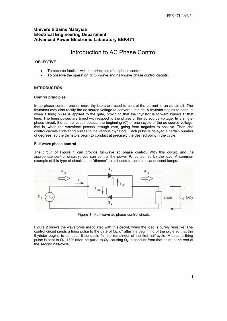
The circuit of Figure 1 can provide full-wave ac phase control. With this circuit, and theappropriate control circuitry, you can control the power PO consumed by the load. A commonexample of this type of circuit is the "dimmer" circuit used to control incandescent lamps.
Figure 1: Full-wave ac phase control circuit.
Figure 2 shows the waveforms associated with this circuit, when the load is purely resistive. Thecontrol circuit sends a firing pulse to the gate of Q1, α° after the beginning of the cycle so that thisthyristor begins to conduct. lt conducts for the remainder of the first half-cycle. A second firingpulse is sent to Q1, 180° after the pulse to Q1, causing Q2 to conduct from that point to the end of the second half-cycle.
7/15/2019 Exp 5 Intro to AC Phase Control
http://slidepdf.com/reader/full/exp-5-intro-to-ac-phase-control 2/8
EEK 471 LAB 5
2
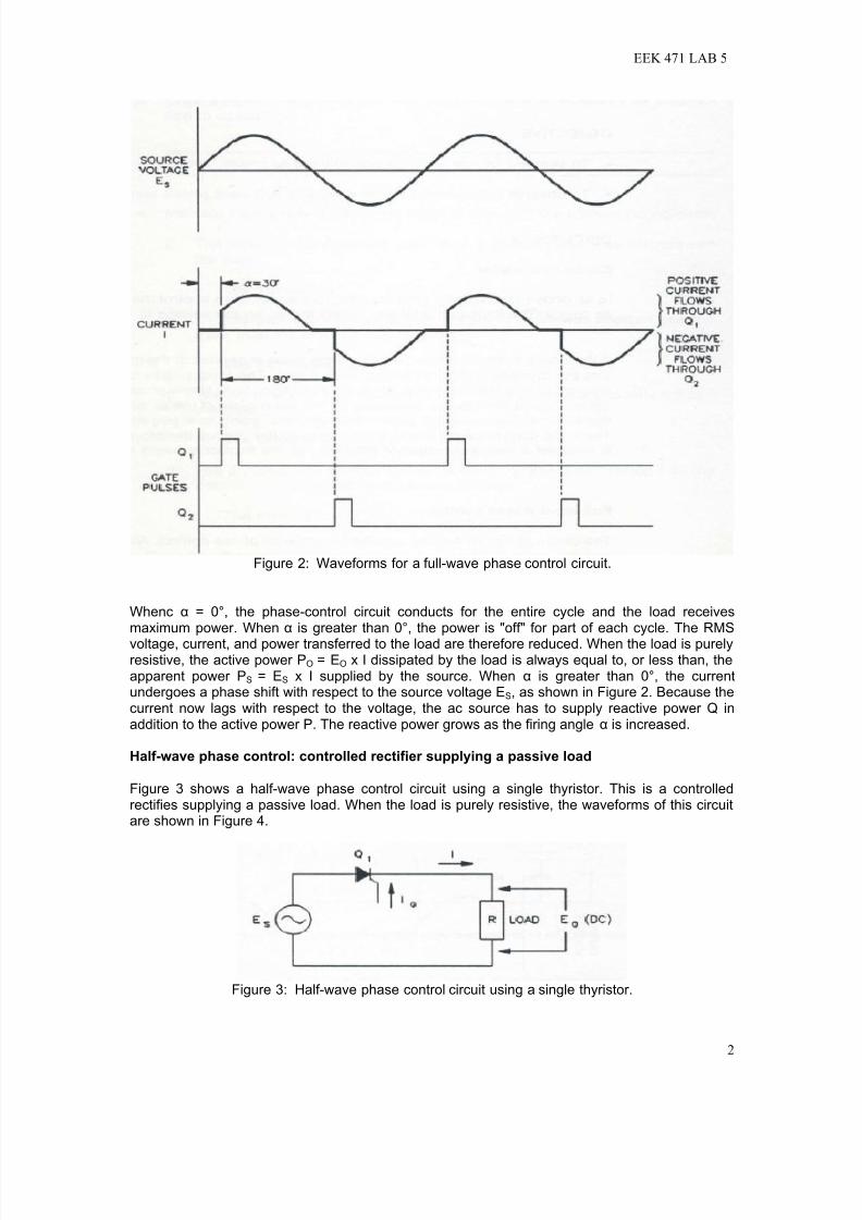
Figure 2: Waveforms for a full-wave phase control circuit.
Whenc α = 0°, the phase-control circuit conducts for the entire cycle and the load receivesmaximum power. When α is greater than 0°, the power is "off" for part of each cycle. The RMS
voltage, current, and power transferred to the load are therefore reduced. When the load is purelyresistive, the active power PO = EO x I dissipated by the load is always equal to, or less than, theapparent power PS = ES x I supplied by the source. When α is greater than 0°, the currentundergoes a phase shift with respect to the source voltage ES, as shown in Figure 2. Because thecurrent now lags with respect to the voltage, the ac source has to supply reactive power Q inaddition to the active power P. The reactive power grows as the firing angle α is increased.
Half-wave phase control: controlled rectifier supplying a passive load
Figure 3 shows a half-wave phase control circuit using a single thyristor. This is a controlledrectifies supplying a passive load. When the load is purely resistive, the waveforms of this circuitare shown in Figure 4.
Figure 3: Half-wave phase control circuit using a single thyristor.
7/15/2019 Exp 5 Intro to AC Phase Control
http://slidepdf.com/reader/full/exp-5-intro-to-ac-phase-control 3/8
EEK 471 LAB 5
3
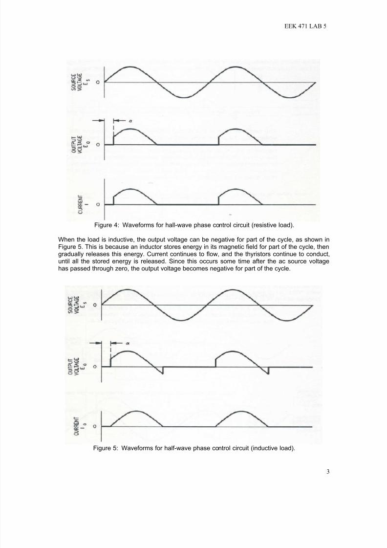
Figure 4: Waveforms for hall-wave phase control circuit (resistive load).
When the load is inductive, the output voltage can be negative for part of the cycle, as shown inFigure 5. This is because an inductor stores energy in its magnetic field for part of the cycle, thengradually releases this energy. Current continues to flow, and the thyristors continue to conduct,until all the stored energy is released. Since this occurs some time after the ac source voltagehas passed through zero, the output voltage becomes negative for part of the cycle.
Figure 5: Waveforms for half-wave phase control circuit (inductive load).

7/15/2019 Exp 5 Intro to AC Phase Control
http://slidepdf.com/reader/full/exp-5-intro-to-ac-phase-control 4/8
EEK 471 LAB 5
4
The negative part of the output voltage waveform reduces the average output voltage EO. Toprevent the output voltage from going negative, a free-wheeling diode can be placed in the circuitas shown in Figure 6. When the output voltage begins to go negative, the free-wheeling diodebegins to conduct. This maintains the output voltage at approximately zero while the energystored in the inductor is being released. The output voltage waveform is the same as for a purelyresistive load (Figure 4), and the average output voltage is therefore greater than it would bewithout the free-wheeling diode.
Figure 6: Half-wave phase control circuit with free-wheeling diode.
EQUIPMENTS
EMS 8821 Enclosure Power Supply
EMS 8840-0A PE Power Supply
EMS 8841-2A Power Thyristor Module
EMS 9030-30 Thyristor Firing Unit
EMS 8425 Lab-Volt AC Ammeter
EMS 8426 Lab-Volt AC Voltmeter
EMS 8412-05 Lab-Volt DC Voltmeter/Ammeter
EMS 8311 Variable Resistance EMS 8325 Smoothing Inductor
EMS 9056-15 and EMS 9056-05 Voltage/Current Isolator
24V AC Power Switch
Textronic Oscilloscope
Connection Leads
WARNINGS
The voltages and currents that are used during this lab are larger and rated at 240V AC Line-to-
Neutral with current as high as 20 amps (or higher if circuits are improperly connected). Pleasetake the proper precautions and use your head before touching any circuitry. NEVER change anycircuit connections while the power supply is turned on. Ask the demonstrator to check your
connections before turning on the switches. And follow the rating of voltmeters and ammetersgiven to prevent equipments from damaged.
7/15/2019 Exp 5 Intro to AC Phase Control
http://slidepdf.com/reader/full/exp-5-intro-to-ac-phase-control 5/8
EEK 471 LAB 5
5
Experiment: Part IFull-wave phase control
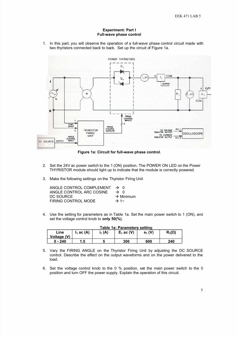
1. In this part, you will observe the operation of a full-wave phase control circuit made withtwo thyristors connected back to back. Set up the circuit of Figure 1a.
Figure 1a: Circuit for full-wave phase control.
2. Set the 24V ac power switch to the 1 (ON) position. The POWER ON LED on the Power THYRISTOR module should light up to indicate that the module is correctly powered.
3. Make the following settings on the Thyristor Firing Unit
ANGLE CONTROL COMPLEMENT 0 ANGLE CONTROL ARC COSINE 0DC SOURCE MinimumFIRING CONTROL MODE 1~
4. Use the setting for parameters as in Table 1a. Set the main power switch to 1 (ON), andset the voltage control knob to only 50(%).
Table 1a: Parameters setting
Line
Voltage (V)
I1 ac (A) i1 (A) E1 ac (V) e1 (V) R1(Ω)
0 - 240 1.5 5 300 600 240
5. Vary the FIRING ANGLE on the Thyristor Firing Unit by adjusting the DC SOURCEcontrol. Describe the effect on the output waveforms and on the power delivered to theload.
6. Set the voltage control knob to the 0 % position, set the main power switch to the 0position and turn OFF the power supply. Explain the operation of this circuit.
7/15/2019 Exp 5 Intro to AC Phase Control
http://slidepdf.com/reader/full/exp-5-intro-to-ac-phase-control 6/8
EEK 471 LAB 5
6
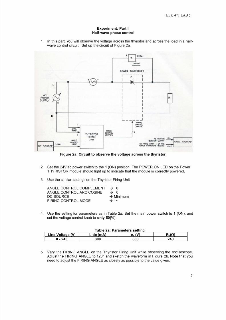
Experiment: Part IIHalf-wave phase control
1. In this part, you will observe the voltage across the thyristor and across the load in a half-wave control circuit. Set up the circuit of Figure 2a.
Figure 2a: Circuit to observe the voltage across the thyristor.
2. Set the 24V ac power switch to the 1 (ON) position. The POWER ON LED on the Power THYRISTOR module should light up to indicate that the module is correctly powered.
3. Use the similar settings on the Thyristor Firing Unit
ANGLE CONTROL COMPLEMENT 0 ANGLE CONTROL ARC COSINE 0DC SOURCE MinimumFIRING CONTROL MODE 1~
4. Use the setting for parameters as in Table 2a. Set the main power switch to 1 (ON), andset the voltage control knob to only 50(%).
Table 2a: Parameters setting
Line Voltage (V) I1 dc (mA) e1 (V) R1(Ω)
0 - 240 300 600 240
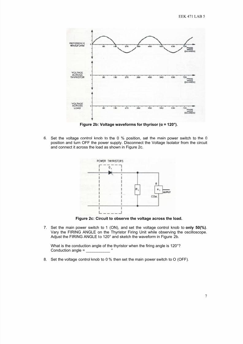
5. Vary the FIRING ANGLE on the Thyristor Firing Unit while observing the oscilloscope. Adjust the FIRING ANGLE to 120° and sketch the waveform in Figure 2b. Note that youneed to adjust the FIRING ANGLE as closely as possible to the value given.
7/15/2019 Exp 5 Intro to AC Phase Control
http://slidepdf.com/reader/full/exp-5-intro-to-ac-phase-control 7/8
EEK 471 LAB 5
7
Figure 2b: Voltage waveforms for thyrisor (α = 120°).
6. Set the voltage control knob to the 0 % position, set the main power switch to the 0position and turn OFF the power supply. Disconnect the Voltage Isolator from the circuitand connect it across the load as shown in Figure 2c.
Figure 2c: Circuit to observe the voltage across the load.
7. Set the main power switch to 1 (ON), and set the voltage control knob to only 50(%).Vary the FIRING ANGLE on the Thyristor Firing Unit while observing the oscilloscope. Adjust the FIRING ANGLE to 120° and sketch the waveform in Figure 2b.
What is the conduction angle of the thyristor when the firing angle is 120°?Conduction angle = ___________ °
8. Set the voltage control knob to 0 % then set the main power switch to O (OFF).

7/15/2019 Exp 5 Intro to AC Phase Control
http://slidepdf.com/reader/full/exp-5-intro-to-ac-phase-control 8/8
EEK 471 LAB 5
8
REVIEW QUESTIONS
1. What point in a single-phase ac waveform is used as a reference point for timing thethyristor gate pulses?
2. Why are the gate pulses in a thyristor circuit delayed with respect to the reference point.
3. What is the relationship of the gate pulses to the two thyristors in a full-wave ac phasecontrol circuit?
4. Why does the source for a thyristor circuit sometimes have to supply reactive power?
5. What is the advantage of using a thyristor in a battery charging circuit?