
EXOR Asset Manager User Guide - Bentley · EXOR Asset Manager User Guide Trademark Bentley and the...
291
EXOR Asset Manager User Guide March 2014 Version: 4.7 Submitted by: Bentley Systems (UK) Ltd., 9th Floor, 20 Gracechurch Street, London EC3V 0BG
Transcript of EXOR Asset Manager User Guide - Bentley · EXOR Asset Manager User Guide Trademark Bentley and the...

EXOR
Asset Manager User Guide
March 2014
Version: 4.7
Submitted by:
Bentley Systems (UK) Ltd.,
9th Floor,
20 Gracechurch Street,
London
EC3V 0BG

EXOR
ASSET MANAGER USER GUIDE
DOCUMENT TRACKER
Version: 4.7 i
CONFIDENTIALITY STATEMENT
The contents of this document, including system ideas and concepts, are confidential and proprietary in nature and are not to be distributed in any form without the prior written consent of Bentley, Inc.
EXOR Asset Manager User Guide
Trademark
Bentley and the "B" Bentley logo are either registered or unregistered trademarks or service marks of
Bentley Systems, Incorporated, or one of its direct or indirect wholly-owned subsidiaries.
Other brands and product names are trademarks of their respective owners.
Copyright
Copyright © 2013 Bentley Systems, Incorporated.
All Rights Reserved.
Including software, file formats, and audiovisual displays; may only be used pursuant to applicable
software license agreement; contains confidential and proprietary information of Bentley Systems,
Incorporated and/or third parties which is protected by copyright and trade secret law and may not be
provided or otherwise made available without proper authorization.
Restricted Rights Legend
If this software is acquired for or on behalf of the United States of America, its agencies and/or
instrumentalities ("U.S. Government"), it is provided with restricted rights. This software and
accompanying documentation are "commercial computer software" and "commercial computer software
documentation", respectively, pursuant to 48 C.F.R. 12.212 and 227.7202, and "restricted computer
software" pursuant to 48 C.F.R. 52.227-19(a), as applicable. Use, modification, reproduction, release,
performance, display or disclosure of this software and accompanying documentation by the U.S.
Government are subject to restrictions as set forth in this Agreement and pursuant to 48 C.F.R. 12.212,
52.227-19, 227.7202, and 1852.227-86, as applicable.
Contractor/Manufacturer is Bentley Systems, Incorporated, 685 Stockton Drive, Exton, PA 19341-0678.
Unpublished - rights reserved under the Copyright Laws of the United States and International treaties.

EXOR
ASSET MANAGER USER GUIDE
DOCUMENT TRACKER
Version: 4.7 ii
CONFIDENTIALITY STATEMENT
The contents of this document, including system ideas and concepts, are confidential and proprietary in nature and are not to be distributed in any form without the prior written consent of Bentley, Inc.
Document Tracker
Document Details
File:
Asset Manager User Guide v4.7.docx
Prepared by:
T.C. Stewart
Manual Name:
Asset Manager User Guide
Reviewed by:
Version:
4.7
Approved for issue by:
T.C. Stewart
Date of Issue:
March 2014
Product Manager:
T.C. Stewart
File Name:
Document Centre/Exor/Product Manuals/4.7.0.0 Product Manuals/4.7 completed documentation/Asset Manager User Guide v4.7.docx
Document Version Control
Revision Date By Chapter/Page Description
1 18-July-2208 CS 19 Filled objects corrected
2 Nov 2010 IS Reviewed for 4.3 release
3 May 2011 IS None No changes for 4.4
4 Nov 2011 IS None No changes for 4.5
5 Oct 2012 IS All Document reviewed and updated for 4.6 release. Included the addition of Navigator button on NM0560, NM0590, NM0570, NM0510
6 Mar 2014 BA/IS All Re-formatted into Bentley template

EXOR
ASSET MANAGER USER GUIDE
TABLE OF CONTENTS
Version: 4.7 iii
CONFIDENTIALITY STATEMENT
The contents of this document, including system ideas and concepts, are confidential and proprietary in nature and are not to be distributed in any form without the prior written consent of Bentley, Inc.
Table of Contents
1 Introduction ........................................................................................................................................... 1
2 Asset Management ................................................................................................................................ 2
2.1 Asset Maintenance –NM0590 ....................................................................................................... 3
2.1.1 Restrict Search by Network Location/Locate Asset by Route .............................................. 5
2.1.2 Querying Assets by Location ................................................................................................ 5
2.1.3 Extent Limits ......................................................................................................................... 8
2.1.4 Scenario 1 .............................................................................................................................. 8
2.1.5 Scenario 2 .............................................................................................................................. 9
2.1.6 Scenario 3 .............................................................................................................................. 9
2.1.7 Sub Class ............................................................................................................................... 9
2.1.8 Ambiguous References ....................................................................................................... 10
2.1.9 Restrict to Exclusive ........................................................................................................... 11
2.1.10 Start Point ............................................................................................................................ 12
2.1.11 End Point ............................................................................................................................. 12
2.1.12 Create new Assets on a linear network ............................................................................... 12
2.1.13 Asset Grid ........................................................................................................................... 14
2.1.14 ‘Fixed’ Attribute Panel ........................................................................................................ 17
2.1.15 Flexible Attribute Panel ...................................................................................................... 20
2.1.16 Querying Exists Assets ....................................................................................................... 21
2.1.17 Advanced Query ................................................................................................................. 23
2.1.18 Assets (Defining Query Types) ........................................................................................... 25
2.1.19 Asset Types Panel ............................................................................................................... 26
2.1.20 Attributes Panel ................................................................................................................... 27
2.1.21 Values Panel ........................................................................................................................ 28
2.1.22 Viewing an Assets Location ............................................................................................... 29
2.1.23 Locate/Relocate or Append a Location to an Asset ............................................................ 31
2.1.24 Route Panel ......................................................................................................................... 32
2.1.25 Sub Class Panel ................................................................................................................... 32
2.1.26 Start Panel ........................................................................................................................... 32
2.1.27 End Panel ............................................................................................................................ 33
2.1.28 Extent Limits ....................................................................................................................... 34
2.1.29 Scenario 1 ............................................................................................................................ 34
2.1.30 Scenario 2 ............................................................................................................................ 34
2.1.31 Scenario 3 ............................................................................................................................ 35
2.1.32 Sub Class ............................................................................................................................. 35
2.1.33 Restrict to Exclusive ........................................................................................................... 35

EXOR
ASSET MANAGER USER GUIDE
TABLE OF CONTENTS
Version: 4.7 iv
CONFIDENTIALITY STATEMENT
The contents of this document, including system ideas and concepts, are confidential and proprietary in nature and are not to be distributed in any form without the prior written consent of Bentley, Inc.
2.1.34 Ambiguous References ....................................................................................................... 36
2.1.35 Start Point ............................................................................................................................ 38
2.1.36 End Point ............................................................................................................................. 39
2.1.37 Locate an Asset using a saved Extent ................................................................................. 40
2.1.38 Locate an Asset using Reference Post Referencing ............................................................ 42
2.1.39 Route Panel ......................................................................................................................... 44
2.1.40 Start/End Reference ............................................................................................................ 44
2.1.41 View an Asset Location ...................................................................................................... 46
2.1.42 Viewing an Asset Location using Reference Post Referencing .......................................... 48
2.1.43 Closing an Asset.................................................................................................................. 49
2.1.44 Managing Hierarchical Assets ............................................................................................ 50
2.1.45 Creating a new Asset Hierarchy .......................................................................................... 50
2.1.46 Navigator ............................................................................................................................. 51
2.1.47 Viewing Assets Attribute within the Matrix Grid ............................................................... 51
2.1.48 Viewing an Asset on the Map ............................................................................................. 54
2.1.49 Selecting Assets using the Map .......................................................................................... 55
2.1.50 Selecting Assets using the Asset Maintenance Map ........................................................... 55
2.1.51 Selecting Assets Using Locator as a List Of Values ........................................................... 58
2.2 Asset Items – NM0510 ............................................................................................................... 60
2.2.1 Asset Items .......................................................................................................................... 61
2.2.2 Attributes ............................................................................................................................. 63
2.2.3 Find Assets .......................................................................................................................... 66
2.2.4 Find Assets (NORMAL Access Mode) .............................................................................. 67
2.2.5 Location Panel (Standard and Advanced modes) ............................................................... 67
2.2.6 Extent Limits ....................................................................................................................... 69
2.2.7 Scenario 1 ............................................................................................................................ 69
2.2.8 Scenario 2 ............................................................................................................................ 69
2.2.9 Scenario 3 ............................................................................................................................ 69
2.2.10 Sub Class ............................................................................................................................. 70
2.2.11 Restrict to Exclusive ........................................................................................................... 70
2.2.12 Ambiguous References ....................................................................................................... 71
2.2.13 Start Point ............................................................................................................................ 72
2.2.14 End Point ............................................................................................................................. 72
2.2.15 Point Items Filter ................................................................................................................. 73
2.2.16 Standard Mode .................................................................................................................... 74
2.2.17 Advanced Mode .................................................................................................................. 75
2.2.18 Attributes Panel ................................................................................................................... 76
2.2.19 Values Panel ........................................................................................................................ 77

EXOR
ASSET MANAGER USER GUIDE
TABLE OF CONTENTS
Version: 4.7 v
CONFIDENTIALITY STATEMENT
The contents of this document, including system ideas and concepts, are confidential and proprietary in nature and are not to be distributed in any form without the prior written consent of Bentley, Inc.
2.2.20 Matching Items ................................................................................................................... 79
2.2.21 Location Panel..................................................................................................................... 80
2.2.22 Find Assets (READONLY access Mode) ........................................................................... 82
2.2.23 Locations ............................................................................................................................. 83
2.2.24 Viewing an Asset Location using Reference Post Referencing .......................................... 86
2.2.25 Locate Asset ........................................................................................................................ 87
2.2.26 Locate a Continuous Item ................................................................................................... 88
2.2.27 Extent Limits ....................................................................................................................... 89
2.2.28 Scenario 1 ............................................................................................................................ 89
2.2.29 Scenario 2 ............................................................................................................................ 89
2.2.30 Scenario 3 ............................................................................................................................ 90
2.2.31 Sub Class ............................................................................................................................. 90
2.2.32 Restrict to Exclusive ........................................................................................................... 90
2.2.33 Ambiguous References ....................................................................................................... 91
2.2.34 Start Point ............................................................................................................................ 93
2.2.35 End Point ............................................................................................................................. 94
2.2.36 Locate a Point Item ............................................................................................................. 95
2.2.37 Locate Asset using a Saved Network Extent ...................................................................... 97
2.2.38 Locate an Asset using Reference Post Referencing ............................................................ 99
2.2.39 Route Panel ....................................................................................................................... 101
2.2.40 Start/End Reference .......................................................................................................... 101
2.2.41 Hierarchy ........................................................................................................................... 104
2.2.42 Groupings .......................................................................................................................... 105
2.2.43 Asset Location History ...................................................................................................... 106
2.2.44 Copy Asset ........................................................................................................................ 107
2.2.45 End Location ..................................................................................................................... 108
2.2.46 Navigator ........................................................................................................................... 109
2.3 Assets on a Route – NM0560 ................................................................................................... 110
2.3.1 Assets on a Route selection Wizard .................................................................................. 112
2.3.2 Extent Limits ..................................................................................................................... 114
2.3.3 Scenario 1 .......................................................................................................................... 114
2.3.4 Scenario 2 .......................................................................................................................... 115
2.3.5 Scenario 3 .......................................................................................................................... 115
2.3.6 Sub Class ........................................................................................................................... 115
2.3.7 Restrict to Exclusive ......................................................................................................... 115
2.3.8 Ambiguous References ..................................................................................................... 116
2.3.9 Start Point .......................................................................................................................... 117
2.3.10 End Point ........................................................................................................................... 117

EXOR
ASSET MANAGER USER GUIDE
TABLE OF CONTENTS
Version: 4.7 vi
CONFIDENTIALITY STATEMENT
The contents of this document, including system ideas and concepts, are confidential and proprietary in nature and are not to be distributed in any form without the prior written consent of Bentley, Inc.
2.3.11 Step 2–Reference Event .................................................................................................... 119
2.3.12 Referencing against the Selected Network ....................................................................... 120
2.3.13 Example 1 ......................................................................................................................... 120
2.3.14 Example 2 ......................................................................................................................... 121
2.3.15 Example 3 ......................................................................................................................... 121
2.3.16 Example 4 ......................................................................................................................... 122
2.3.17 Referencing against Items of an Asset Type ..................................................................... 123
2.3.18 Referencing against a Specific Asset Item ........................................................................ 126
2.3.19 Step 3–Display Items ........................................................................................................ 127
2.3.20 Step 4–Assets (Defining Display Items) ........................................................................... 130
2.3.21 Inv Types Panel ................................................................................................................. 131
2.3.22 Attributes Panel ................................................................................................................. 131
2.3.23 Values Panel ...................................................................................................................... 132
2.3.24 Create a New PBI Query ................................................................................................... 134
2.3.25 Assets on Route Results .................................................................................................... 135
2.3.26 Region of Interest Panel .................................................................................................... 137
2.3.27 Asset Panel ........................................................................................................................ 138
2.3.28 Offsets Panel ..................................................................................................................... 140
2.3.29 Item Attributes Panel ........................................................................................................ 140
2.3.30 Navigator Button ............................................................................................................... 141
2.3.31 Ref Item Attributes............................................................................................................ 142
2.3.32 Item Route Location.......................................................................................................... 142
2.3.33 Item Datum Location ........................................................................................................ 143
2.3.34 Item Groups Location ....................................................................................................... 143
2.3.35 Graphical Strip Map .......................................................................................................... 144
2.3.36 Asset on Route Reports ..................................................................................................... 146
2.3.37 NM0562–Assets on a Route Report–By offset ................................................................. 147
2.3.38 Example when Referencing to Selected Network ............................................................. 148
2.3.39 Example when Referencing to a specific Asset Item ........................................................ 149
2.3.40 Example when Referencing against Items of another Asset Type .................................... 150
2.3.41 NM0563–Asset on a Route Report–By Type and Offset .................................................. 151
2.3.42 Example when Referencing to Selected Network ............................................................. 152
2.3.43 Example when Referencing to a specific Asset Item ........................................................ 153
2.3.44 Example when Referencing against Items of another Asset Type .................................... 154
2.4 Find Assets–NM0570 ............................................................................................................... 155
2.4.1 Location Panel (Standard and Advanced modes) ............................................................. 157
2.4.2 Extent Limits ..................................................................................................................... 159
2.4.3 Scenario 1 .......................................................................................................................... 159

EXOR
ASSET MANAGER USER GUIDE
TABLE OF CONTENTS
Version: 4.7 vii
CONFIDENTIALITY STATEMENT
The contents of this document, including system ideas and concepts, are confidential and proprietary in nature and are not to be distributed in any form without the prior written consent of Bentley, Inc.
2.4.4 Scenario 2 .......................................................................................................................... 160
2.4.5 Scenario 3 .......................................................................................................................... 160
2.4.6 Sub Class ........................................................................................................................... 160
2.4.7 Restrict to Exclusive ......................................................................................................... 161
2.4.8 Ambiguous References ..................................................................................................... 162
2.4.9 Start Point .......................................................................................................................... 162
2.4.10 End Point ........................................................................................................................... 163
2.4.11 Point Items Filter ............................................................................................................... 164
2.4.12 Standard Mode .................................................................................................................. 165
2.4.13 Advanced Mode ................................................................................................................ 166
2.4.14 Attributes Panel ................................................................................................................. 167
2.4.15 Values Panel ...................................................................................................................... 168
2.4.16 Matching Items ................................................................................................................. 170
2.4.17 Navigator Button ............................................................................................................... 171
2.4.18 Location Panel................................................................................................................... 172
2.5 Global Asset Update – NM0530 ............................................................................................... 174
2.5.1 Global Asset Update ......................................................................................................... 175
2.6 Delete Global Assets – NM0575 .............................................................................................. 177
2.6.1 Delete Global Assets ......................................................................................................... 178
2.6.2 Step 1–Network Restriction .............................................................................................. 178
2.6.3 Step 2 – Asset Categories .................................................................................................. 181
2.6.4 Step 3 – Assets to Process ................................................................................................. 182
2.6.5 Hierarchical Assets ........................................................................................................... 184
2.6.6 Step 4 –Results Log .......................................................................................................... 185
2.7 Asset Admin Unit Security Maintenance–NM1861 ................................................................. 186
2.7.1 Asset Admin Unit Security Maintenance .......................................................................... 188
3 Asset Queries .................................................................................................................................... 189
3.1 PBI Query Setup – NM7040 ..................................................................................................... 190
3.1.1 Example 1–Filtering on Network Attributes ..................................................................... 192
3.1.2 Example 2–Filtering on Single Asset Type ...................................................................... 192
3.1.3 Example 3–Filtering on Multiple Asset Types ................................................................. 192
3.1.4 Example 4 ......................................................................................................................... 194
3.1.5 PBI Queries ....................................................................................................................... 197
3.1.6 Query Panel ....................................................................................................................... 198
3.1.7 Item Type Panel ................................................................................................................ 198
3.1.8 Attributes Panel ................................................................................................................. 199
3.1.9 Values Panel ...................................................................................................................... 200
3.1.10 PBI Toolbar ....................................................................................................................... 202

EXOR
ASSET MANAGER USER GUIDE
TABLE OF CONTENTS
Version: 4.7 viii
CONFIDENTIALITY STATEMENT
The contents of this document, including system ideas and concepts, are confidential and proprietary in nature and are not to be distributed in any form without the prior written consent of Bentley, Inc.
3.1.11 Create New Attribute Set .................................................................................................. 203
3.2 PBI Query Results – NM7041 .................................................................................................. 204
3.2.1 Displaying PBI Query Results by User Preferred LRM ................................................... 205
3.2.2 PBI Query Results ............................................................................................................. 206
3.2.3 Results ............................................................................................................................... 207
3.2.4 Route Tab (middle panel) ................................................................................................. 208
3.2.5 Datum Tab (middle panel) ................................................................................................ 209
3.2.6 Route Tab (bottom panel) ................................................................................................. 209
3.2.7 Datum Tab (bottom panel) ................................................................................................ 210
3.2.8 PBI Jobs ............................................................................................................................ 211
3.3 Merge Query Defaults –NM7053 ............................................................................................. 212
3.3.1 Merge Query Defaults ....................................................................................................... 213
3.4 Merge Queries – NM7050 ........................................................................................................ 214
3.4.2 Attribute Bandings ............................................................................................................ 217
3.4.3 Merge Queries ................................................................................................................... 218
3.4.4 Merge Query Roles ........................................................................................................... 220
3.4.5 User Security with Merge Queries .................................................................................... 224
3.5 Merge Query Results – NM7051 .............................................................................................. 225
3.5.1 Route Tab (middle panel) ................................................................................................. 228
3.5.2 Datum Tab (middle panel) ................................................................................................ 229
3.5.3 Route Tab (bottom panel) ................................................................................................. 230
3.5.4 Datum Tab (bottom panel) ................................................................................................ 231
3.5.5 Asset Tab .......................................................................................................................... 232
3.5.6 Merge Jobs ........................................................................................................................ 232
3.5.7 Displaying Merge Query Results by User Preferred LRM ............................................... 233
3.6 Merge Results Extract – NM7057 ............................................................................................ 234
3.6.1 Example of Flat File Text Format Extract ........................................................................ 236
3.6.2 Example of CSV Format Extract ...................................................................................... 237
3.6.3 Example of HTML Format ............................................................................................... 237
3.7 Merge File Extract Definition – NM7055 ................................................................................. 238
3.7.1 Merge Output File Panel ................................................................................................... 242
3.7.2 File Columns Panel ........................................................................................................... 244
3.7.3 Decode Values .................................................................................................................. 246
3.8 Engineering Dynamic Segmentation Functions ........................................................................ 247
3.8.1 Mean (NM3ENG_DYNSEG.GET_MEAN_VALUE) ..................................................... 249
3.8.2 Variance (NM3ENG_DYNSEG.GET_VARIANCE) ...................................................... 250
3.8.3 Biased Variance (NM3ENG_DYNSEG.GET_BIASED_VARIANCE) .......................... 251
3.8.4 Standard Deviation (NM3ENG_DYNSEG.GET_STANDARD_DEVIATION) ............. 252

EXOR
ASSET MANAGER USER GUIDE
TABLE OF CONTENTS
Version: 4.7 ix
CONFIDENTIALITY STATEMENT
The contents of this document, including system ideas and concepts, are confidential and proprietary in nature and are not to be distributed in any form without the prior written consent of Bentley, Inc.
3.8.5 Biased Standard Deviation
(NM3ENG_DYNSEG.GET_BIASED_STANDARD_DEVIATION) ............................................ 253
3.8.6 Median (NM3ENG_DYNSEG.GET_MEDIAN_VALUE) .............................................. 254
3.8.7 Length Weighted Average (NM3ENG_DYNSEG.GET_LENGTH_WEIGHTED_AVE)
255
3.8.8 First Value (NM3ENG_DYNSEG.GET_FIRST_VALUE) ............................................. 256
3.8.9 Last Value (NM3ENG_DYNSEG.GET_LAST_VALUE)............................................... 257
3.8.10 Minimum Value (NM3ENG_DYNSEG.GET_MINIMUM_VALUE) ............................ 258
3.8.11 Maximum Value (NM3ENG_DYNSEG.GET_MAXIMUM_VALUE) .......................... 259
3.8.12 Most Common Value (NM3ENG_DYNSEG.GET_MOST_COMMON_VALUE) ........ 260
3.8.13 Most Common Value Dets
(NM3ENG_DYNSEG.GET_MOST_COMMON_VALUE_DETS) ............................................... 261
3.8.14 Most Frequent Value (NM3ENG_DYNSEG.GET_MOST_FREQUENT_VALUE) ...... 262
3.8.15 Most Frequent Value Dets
(NM3ENG_DYNSEG.GET_MOST_FREQUENT_VALUE_DETS) ............................................. 263
3.8.16 Sum (NM3ENG_DYNSEG.GET_SUM) ......................................................................... 264
3.8.17 Value Count (NM3ENG_DYNSEG.GET_VALUE_COUNT) ........................................ 265
3.8.18 Value Distributions (NM3ENG_DYNSEG.GET_VALUE_DISTRIBUTIONS) ............ 266
3.9 Web Based Engineering Dynamic Segmentation–NMWEB0020 ............................................ 267
3.9.1 General Information .......................................................................................................... 267
3.9.2 Logging onto a Web Session ............................................................................................ 269
3.9.3 Hyper Links ...................................................................................................................... 269
3.9.4 Source of Area for EDS .................................................................................................... 270
3.9.5 Functions Page .................................................................................................................. 272
3.9.6 EDS Results ...................................................................................................................... 274
3.10 Reconcile Map Capture Load Errors – NM0511 ...................................................................... 275
3.10.1 Details ............................................................................................................................... 276
3.10.2 Known Issues .................................................................................................................... 279
3.10.3 MapCapture Load Failures ................................................................................................ 280

EXOR
ASSET MANAGER USER GUIDE
INTRODUCTION
Version: 4.7 1
CONFIDENTIALITY STATEMENT
The contents of this document, including system ideas and concepts, are confidential and proprietary in nature and are not to be distributed in any form without the prior written consent of Bentley, Inc.
1 Introduction
This Guide provides information on the use of Asset Manager from V3 onwards. It is aimed at general users who wish to
carry out simple management and query of asset/Asset data.
More information on asset modeling is provided in the Asset Manager System Administrator’s Guide.

EXOR
ASSET MANAGER USER GUIDE
ASSET MANAGEMENT
Version: 4.7 2
CONFIDENTIALITY STATEMENT
The contents of this document, including system ideas and concepts, are confidential and proprietary in nature and are not to be distributed in any form without the prior written consent of Bentley, Inc.
2 Asset Management
Figure 1–Asset Maintenance Menu
This chapter describes the modules and process’s required for managing Asset data within Exor. The following modules
are detailed:
Asset Maintenance – NM0590
Asset Items – NM0510
Assets on a Route – NM0560
Find Assets–NM0570
Global Asset Update – NM0530
Delete Global Assets – NM0575
Asset Admin Unit Security Maintenance–NM1861

EXOR
ASSET MANAGER USER GUIDE
ASSET MANAGEMENT
Version: 4.7 3
CONFIDENTIALITY STATEMENT
The contents of this document, including system ideas and concepts, are confidential and proprietary in nature and are not to be distributed in any form without the prior written consent of Bentley, Inc.
2.1 Asset Maintenance –NM0590
Figure 2 - Asset Maintenance Menu Option
Road Maintainers are under increasing pressure to deliver Asset Management Plans and Asset Valuation for the Assets
under their stewardship. The base Asset Register is a critical component that underpins these 2 deliverables. One of the
many challenges an Organisation faces is keeping the Asset Register up to date to ensure the Asset Management Plan is
being delivered and to underpin an accurate Asset Valuation.
Using the Asset Maintenance module in combination with our Web Mapping option, Exor can deliver an easy to use map
based Asset maintenance environment which will help an Organisation to meet its service delivery objectives by ensuring
the Asset Register is maintained on time and with high accuracy.
The Asset Maintenance module allows the creation and subsequent maintenance of Assets stored within the Exor system.
Additionally, ANY dataset held within Exor or data held externally to Exor, which has been defined as an ‘External
Asset’ (refer to the Asset Manager System Admin Guide for more information on ‘External Assets’) may be queried,
allowing the Assets defining Attributes to be displayed.
When a search is conducted based upon the Assets located along a Linear Network Type or Group, e.g., a Maintenance
Section or County Route, the resulting Assets are ordered by their Offset measure, relative to the start of the selected
network, with the Start and End measure being displayed within the Asset Grid.
If a non-linear Group is used for a location based Asset search the resulting Assets are ordered by Asset Type. In this case
no Asset locations are displayed within the Asset Grid. An Assets’ location may be viewed relative to the Route(s) (Linear
Group) e.g., Maintenance Section, Groups (non-linear Groups) e.g., a Street and Datum Elements on which the Asset is
placed by pressing the [Asset Locations] button on the Toolbar.
The Asset Maintenance module is designed to allow for fast, accurate data entry by the User. When adding new Assets
that are located along on a linear network e.g., Maintenance Section or Route, the User may initially select the required
Section or Route, then for each Asset simply enter the Start and End measures for each Asset relative to the Route along
with the Assets Attribute values.
Unlocated Assets, i.e., Assets not located directly on a Network, may also be added using the Asset Maintenance module.
Data input accuracy is essential when maintaining a high quality Asset Register. Using the Asset Maintenance module
helps ensure that data input errors are minimised through the use of Attribute Validation. This Validation may take the
form of simple checking for minimum or maximum values or validation against a list of values or may involve complex
Cross Attribute Validation, where the attribute values for an Asset are cross referenced against other attribute values of the
same Asset (refer to the Asset Management System Admin Guide for further details).

EXOR
ASSET MANAGER USER GUIDE
ASSET MANAGEMENT
Version: 4.7 4
CONFIDENTIALITY STATEMENT
The contents of this document, including system ideas and concepts, are confidential and proprietary in nature and are not to be distributed in any form without the prior written consent of Bentley, Inc.
If the Web Mapping option has been licensed and installed and an Asset has a spatial representation, it may be viewed on
the in the web Map by pressing the [Show Map] button on the menu toolbar. When pressed, the map tab will become
the ‘active’ window and the map will zoom and centre on the selected Asset allowing business functions such as creating
an Enquiry or a Defect to be carried out against the Asset.
Note: The Map window within the Asset Maintenance – NM0590 module contains all the business functionality
available within the Locator Module Map Window (refer to the Locator and Web Mapping User Guide).
The Asset Maintenance module also integrates with Document Manager by Exor allowing the retrieval of documents of
any media type (e.g., CAD photographs, video, etc) within a simple and easy to use interface.
Figure 3 – Asset Maintenance

EXOR
ASSET MANAGER USER GUIDE
ASSET MANAGEMENT
Version: 4.7 5
CONFIDENTIALITY STATEMENT
The contents of this document, including system ideas and concepts, are confidential and proprietary in nature and are not to be distributed in any form without the prior written consent of Bentley, Inc.
2.1.1 Restrict Search by Network Location/Locate Asset by Route
Figure 4 – Asset Maintenance - Location
This panel is used in one of two ways depending on whether Assets are being queried or new Assets are being created and
located relative to a Linear Network or Group, e.g., a Maintenance Section or County Route.
2.1.2 Querying Assets by Location
When querying Assets, a Network restriction may be applied so that only those assets that are located either wholly or
partially within the selected region of interest will be included in the query. By default the [All Items] check box is
checked, which means that queries are not restricted by a Network Location. To define a region of interest on which to
base a query, uncheck the [All Items] option.
All Items (Checkbox)
If this option is selected the Asset query will be based purely on the selection criteria defined and not further restricted by
the location of an Asset. If the option is ‘checked’ the remaining fields within the Location Panel will be disabled.
Name
Enter the required Region Of Interest or select from the Gazetteer (refer the Network Manager User guide). If a Default
Region of Interest has been defined using the User Preferences module (General User Guide) it will be automatically
displayed. Default Regions of Interest allow commonly used network area’s such as Divisions, Council Office area’s or
Regional Office area’s to be pre-selected in various modules within Exor making the system faster and easier to use. If a
Default Region of Interest has been defined it may be overridden if required.
If a Linear Group, e.g., a Maintenance Section or Route is selected, the queried Assets will be ordered by their Start Offset
measure, relative to the start of the selected network, with the Start and End measure being displayed within the Asset
Grid.
If a non-linear Group is used for a location based Asset search the resulting Assets are ordered by Asset Type. In this case
no Asset locations are displayed within the Asset Grid. An Assets’ location may be viewed relative to the Route(s) (Linear
Group) e.g., Maintenance Section, Groups (non-linear Groups) e.g., a Street and Datum Elements on which the Asset is
placed by pressing the [Asset Locations] button on the Toolbar.
EXOR
ASSET MANAGER USER GUIDE
ASSET MANAGEMENT
Version: 4.7 6
CONFIDENTIALITY STATEMENT
The contents of this document, including system ideas and concepts, are confidential and proprietary in nature and are not to be distributed in any form without the prior written consent of Bentley, Inc.
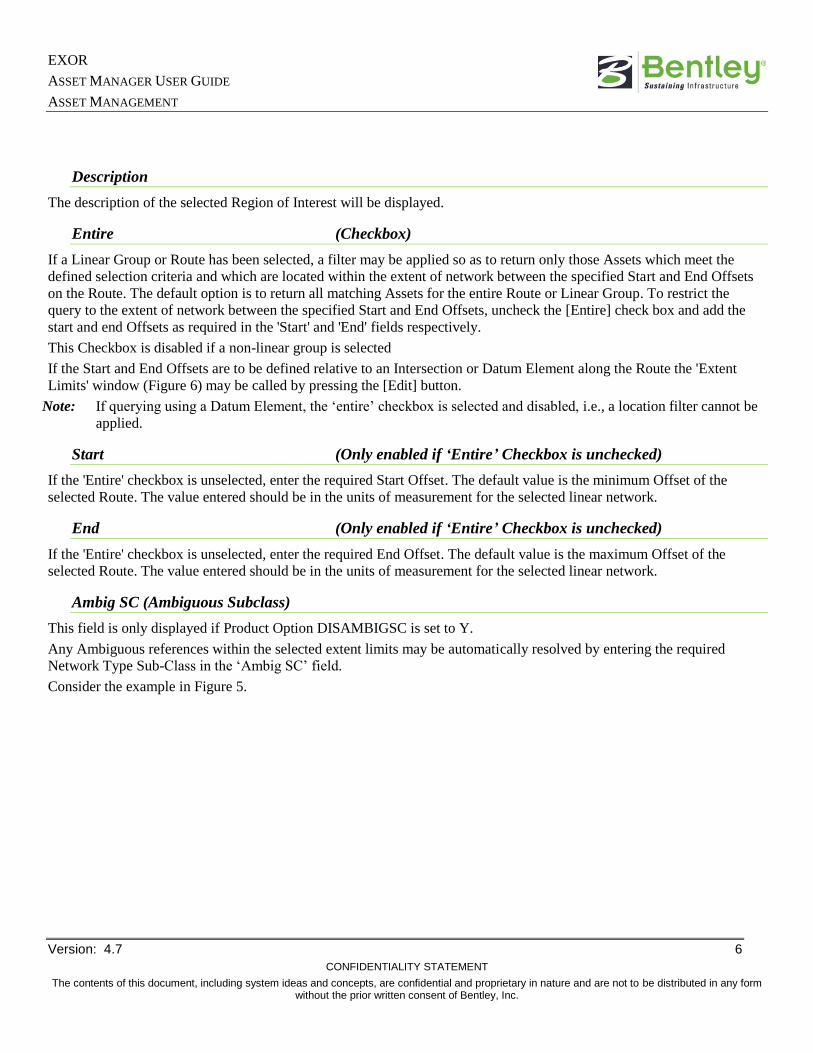
Description
The description of the selected Region of Interest will be displayed.
Entire (Checkbox)
If a Linear Group or Route has been selected, a filter may be applied so as to return only those Assets which meet the
defined selection criteria and which are located within the extent of network between the specified Start and End Offsets
on the Route. The default option is to return all matching Assets for the entire Route or Linear Group. To restrict the
query to the extent of network between the specified Start and End Offsets, uncheck the [Entire] check box and add the
start and end Offsets as required in the 'Start' and 'End' fields respectively.
This Checkbox is disabled if a non-linear group is selected
If the Start and End Offsets are to be defined relative to an Intersection or Datum Element along the Route the 'Extent
Limits' window (Figure 6) may be called by pressing the [Edit] button.
Note: If querying using a Datum Element, the ‘entire’ checkbox is selected and disabled, i.e., a location filter cannot be
applied.
Start (Only enabled if ‘Entire’ Checkbox is unchecked)
If the 'Entire' checkbox is unselected, enter the required Start Offset. The default value is the minimum Offset of the
selected Route. The value entered should be in the units of measurement for the selected linear network.
End (Only enabled if ‘Entire’ Checkbox is unchecked)
If the 'Entire' checkbox is unselected, enter the required End Offset. The default value is the maximum Offset of the
selected Route. The value entered should be in the units of measurement for the selected linear network.
Ambig SC (Ambiguous Subclass)
This field is only displayed if Product Option DISAMBIGSC is set to Y.
Any Ambiguous references within the selected extent limits may be automatically resolved by entering the required
Network Type Sub-Class in the ‘Ambig SC’ field.
Consider the example in Figure 5.

EXOR
ASSET MANAGER USER GUIDE
ASSET MANAGEMENT
Version: 4.7 7
CONFIDENTIALITY STATEMENT
The contents of this document, including system ideas and concepts, are confidential and proprietary in nature and are not to be distributed in any form without the prior written consent of Bentley, Inc.
Figure 5
The Route displayed in Figure 5 contains a combination of Network Type Subclasses. A query is required within the
extent limits shown, but only where the Network Type Sub Class is either ‘S’ – Single or ‘L’ – Left.
By entering a value of ‘L’ – left in the 'Ambig SC' field, the query will include ALL Elements (or parts of) with a
Network Type Subclass of ‘S’ – Single and those Elements (or parts of) with a Network Type Sub Class of ‘L’ –Left.
Therefore the query would include the following Elements:–
1-S, 2-S, 3-L, 4-L, 5-S, 8-L, 9-L, 12-S

EXOR
ASSET MANAGER USER GUIDE
ASSET MANAGEMENT
Version: 4.7 8
CONFIDENTIALITY STATEMENT
The contents of this document, including system ideas and concepts, are confidential and proprietary in nature and are not to be distributed in any form without the prior written consent of Bentley, Inc.
2.1.3 Extent Limits
Figure 6 – Extent Limits
The Extent Limits window may be called by pressing the [Edit] button and allows the Start and End points on the selected
Route to be defined by Route Offset, Intersection or Section/Datum Offset. For example, to select a Route extent
comprising of the first Kilometre of the Route, the Start Point would be defined as having a Route Offset of ‘0’ and the
End Point defined as having a Route Offset of ‘1’ (assuming the minimum Offset of the Route is Zero)
The tables below show 3 scenarios for Extent Limits, to demonstrate the possibilities.
2.1.4 Scenario 1
Parameters Start Point End Point Result
Route Offset 1 3.5 Elements or partial Elements contained between Route Offset 1 and 3.5 Kilometers
Intersection
Section Offset

EXOR
ASSET MANAGER USER GUIDE
ASSET MANAGEMENT
Version: 4.7 9
CONFIDENTIALITY STATEMENT
The contents of this document, including system ideas and concepts, are confidential and proprietary in nature and are not to be distributed in any form without the prior written consent of Bentley, Inc.
2.1.5 Scenario 2
Parameters Start Point End Point Result
Route Offset 0.24 Elements or partial Elements contained between the Intersection at Node 82730 and Route Offset 0.24
Intersection 082730
Section Offset
2.1.6 Scenario 3
Parameters Start Point End Point Result
Route Offset 5.6 Elements or partial Element contained between 35m along Element H004/1-S and Route Offset 5.6 Kilometers
Intersection
Section Offset H004/1-S
35
2.1.7 Sub Class
Figure 7 - Network Extent Subclass
The ‘Sub Class’ panel of the Extent Limits window allows the User to choose the Sub Class of the Elements, within the
defined extent limits, to be included in the Network Extent. If neither the Sub Class ‘When Ambiguous’ or ‘Restrict to
Exclusive’ field are populated, the Elements of all Sub-Classes within the defined extent limits will be entered into the
Network Extent.

EXOR
ASSET MANAGER USER GUIDE
ASSET MANAGEMENT
Version: 4.7 10
CONFIDENTIALITY STATEMENT
The contents of this document, including system ideas and concepts, are confidential and proprietary in nature and are not to be distributed in any form without the prior written consent of Bentley, Inc.
2.1.8 Ambiguous References
Any Ambiguous references within the selected extent limits may be automatically resolved by entering the required
Network Type Sub-Class in the ‘Subclass When Ambiguous’ field. For example:
Figure 8
The Route displayed in Figure 8 contains a combination of Network Type Subclasses. A Network Extent is required
within the extent limits shown, but only where the Network Type Sub Class is either ‘S’ – Single or ‘L’ – Left.
By entering a value of ‘L’ – Left in the Sub Class ‘When Ambiguous’ field of the extent limits window, the Network
Extent will include ALL Elements (or parts of) with a Network Type Subclass of ‘S’ – Single and those Elements (or parts
of) with a Network Type Sub Class of ‘L’ – Left. Therefore the Network Extent would include the following Elements:–
1-S, 2-S, 3-L, 4-L, 5-S, 8-L, 9-L, 12-S
When the Start and End parameters have been defined press the [OK] button on the Extent Limits window.
EXOR
ASSET MANAGER USER GUIDE
ASSET MANAGEMENT
Version: 4.7 11
CONFIDENTIALITY STATEMENT
The contents of this document, including system ideas and concepts, are confidential and proprietary in nature and are not to be distributed in any form without the prior written consent of Bentley, Inc.
2.1.9 Restrict to Exclusive
Elements may be restricted to a single ‘Exclusive’ Sub Class by selecting the ‘Restrict to Exclusive’ check box and
entering the required Sub-Class in the adjacent field. This will restrict the Elements selected to those that match the
selected Sub Class.
Consider the example in Figure 9.
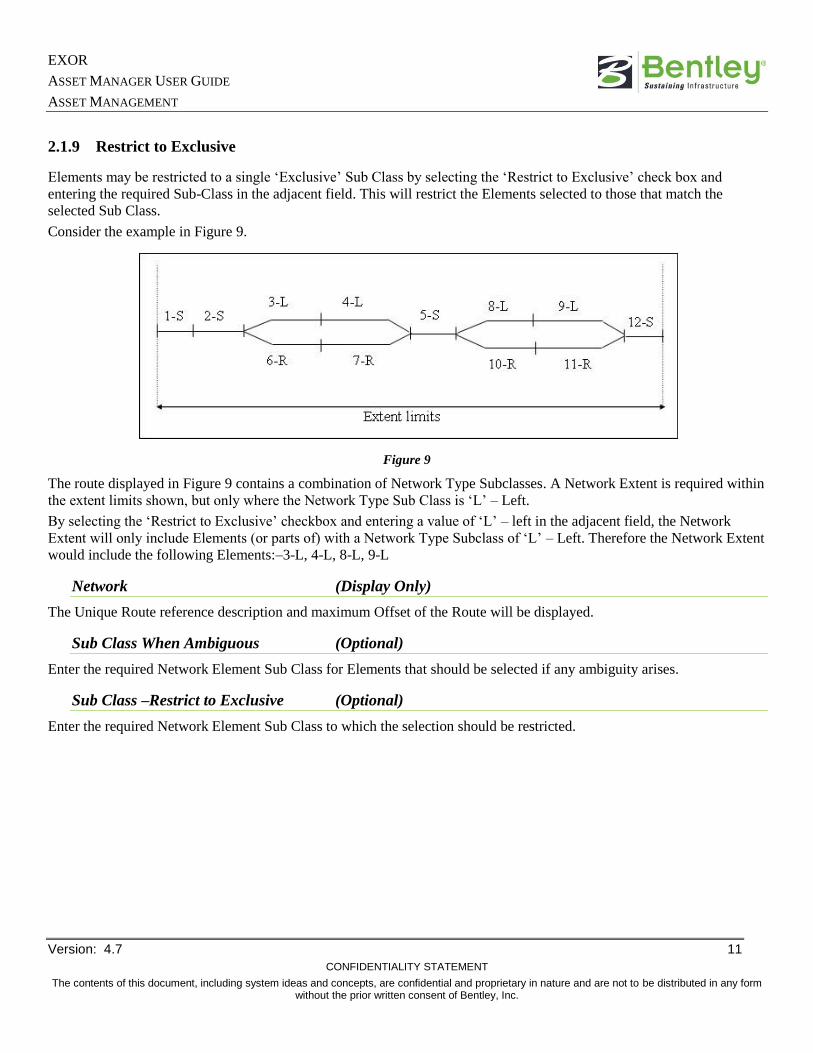
Figure 9
The route displayed in Figure 9 contains a combination of Network Type Subclasses. A Network Extent is required within
the extent limits shown, but only where the Network Type Sub Class is ‘L’ – Left.
By selecting the ‘Restrict to Exclusive’ checkbox and entering a value of ‘L’ – left in the adjacent field, the Network
Extent will only include Elements (or parts of) with a Network Type Subclass of ‘L’ – Left. Therefore the Network Extent
would include the following Elements:–3-L, 4-L, 8-L, 9-L
Network (Display Only)
The Unique Route reference description and maximum Offset of the Route will be displayed.
Sub Class When Ambiguous (Optional)
Enter the required Network Element Sub Class for Elements that should be selected if any ambiguity arises.
Sub Class –Restrict to Exclusive (Optional)
Enter the required Network Element Sub Class to which the selection should be restricted.
EXOR
ASSET MANAGER USER GUIDE
ASSET MANAGEMENT
Version: 4.7 12
CONFIDENTIALITY STATEMENT
The contents of this document, including system ideas and concepts, are confidential and proprietary in nature and are not to be distributed in any form without the prior written consent of Bentley, Inc.
2.1.10 Start Point
Select one of the following Radio button to define the Start Point along the selected Route. The default selection is by
Route Offset.
Route Offset
Enter the Route Offset for the Start Point. This should be entered in the unit of measurement defined for the selected
Group or Network Type. The defined Unit will be displayed adjacent to the Route Offset measure.
Intersection (List)
Enter the Node point of the Intersection for the Start Point. The list of values will display all the Intersection Node details
for the selected Route.
Section Offset (List)
Enter the Unique Element reference for the Start Point. The Element description will be displayed in the adjacent field.
The list of values will display all the Network Element within the selected Route.
Enter the Element Offset in the unit of measurement defined for the Datum Element in Network Types–NM0002. The
measured length of the Element will be displayed in the adjacent field.
2.1.11 End Point
Select one of the following Radio button to define the Start Point along the selected Route. The default selection is by
Route Offset
Route Offset
Enter the Route Offset for the End Point. This should be entered in the unit of measurement defined for the selected
Group or Network Type. The defined Unit will be displayed adjacent to the Route Offset measure.
Intersection (List)
Enter the Node point of the Intersection for the End Point. The list of values will display all the Intersection Node details
for the selected Route.
Section Offset (List)
Enter the Unique Element reference for the End Point. The Element description will be displayed in the adjacent field.
The list of values will display all the Network Element within the selected Route.
Enter the Element Offset in the unit of measurement defined for the Datum Element in Network Types–NM0002. The
measured length of the Element will be displayed in the adjacent field.
2.1.12 Create new Assets on a linear network
When creating located Assets it is possible to ‘pre select’ a linear network e.g., a Maintenance Section or Route, on which
the Assets are to be located. This ensures that the User does not have to repeatedly select the same Network Group for
each Asset. Instead the User merely needs to define the Begin and End offsets for each Asset (note 1–Figure 10).

EXOR
ASSET MANAGER USER GUIDE
ASSET MANAGEMENT
Version: 4.7 13
CONFIDENTIALITY STATEMENT
The contents of this document, including system ideas and concepts, are confidential and proprietary in nature and are not to be distributed in any form without the prior written consent of Bentley, Inc.
When creating located Assets by pre selecting the Route on which they are located, the ‘Entire’ checkbox and any values
entered for the Start and End values (note 2–Figure 10) are disregarded as these are only used when querying existing
Assets.
If a non-linear group or group of groups is selected, this is ignored when creating new assets. To locate Asses in this case
use the [Locate Asset] button on the floating Toolbar (page 31).
Figure 10
Ambig SC (Ambiguous Subclass) List
Note: This field is only displayed if Product Option DISAMBIGSC is set to Y.
Any Ambiguous references within the selected extent limits may be automatically resolved by entering the required
Network Type Sub-Class in the ‘Ambig SC’ field.
Consider the example in Figure 11.
Figure 11
The Route displayed in Figure 11 contains a combination of Network Type Subclasses. A query is required within the
extent limits shown, but only where the Network Type Sub Class is either ‘S’ – Single or ‘L’ – Left.
By entering a value of ‘L’ – left in the 'Ambig SC' field, the query will include ALL Elements (or parts of) with a
Network Type Subclass of ‘S’ – Single and those Elements (or parts of) with a Network Type Sub Class of ‘L’ –Left.
Therefore the query would include the following Elements:–
1-S, 2-S, 3-L, 4-L, 5-S, 8-L, 9-L, 12-S

EXOR
ASSET MANAGER USER GUIDE
ASSET MANAGEMENT
Version: 4.7 14
CONFIDENTIALITY STATEMENT
The contents of this document, including system ideas and concepts, are confidential and proprietary in nature and are not to be distributed in any form without the prior written consent of Bentley, Inc.
2.1.13 Asset Grid
Figure 12 – Asset Grid
The Asset Grid is used to display the Asset Type, Asset Description, Cross Sectional Position (XSP) and in the case of a
linear route being selected, the Begin and End Offsets for each Asset relative to the selected linear group or network.
When existing Assets are queried using a linear group or network, the Assets are ordered by their Begin Offset, relative to
the start of the selected network. To view an Assets location relative to another LRM (Linear referencing method) or
group, press the [Asset Location] button on the floating Toolbar (page 29).
If a non-linear region of interest or no network restriction is selected the ‘Begin’ and ‘End’ columns are not displayed
within the grid as shown in Figure 13.
.

EXOR
ASSET MANAGER USER GUIDE
ASSET MANAGEMENT
Version: 4.7 15
CONFIDENTIALITY STATEMENT
The contents of this document, including system ideas and concepts, are confidential and proprietary in nature and are not to be distributed in any form without the prior written consent of Bentley, Inc.
Figure 13 - Non linear or No location selected
Note:
‘Multipart’ Assets, i.e., Assets with disparate locations, will be displayed on several rows within the Asset Grid,
one row for each distinct location when queried using a linear group or network restriction.
Figure 14 shows an example.
In the example an Asset of an ‘Exclusive’ type (ID1001), i.e., only one Asset of the type may be placed at the
same location within an XSP’, is located on a Route between Offsets 0 and 100.
A second Asset (ID2002) of the same type is subsequently placed on the Route between Offsets 40 and 60. The
location of the existing Asset is automatically updated to reflect this fact resulting in the Asset being located on
the Route between 0 – 40 AND 60 –100, i.e., a ‘Multipart’ Asset.
Figure 14
Note: When queried relative to a linear group or network this Asset would be displayed on separate rows within the
Grid as shown in Figure 15.

EXOR
ASSET MANAGER USER GUIDE
ASSET MANAGEMENT
Version: 4.7 16
CONFIDENTIALITY STATEMENT
The contents of this document, including system ideas and concepts, are confidential and proprietary in nature and are not to be distributed in any form without the prior written consent of Bentley, Inc.
Figure 15 – Asset locations
Asset Type (Required) List
This is the Asset Type code. Only Asset Types to which the User has been granted Role based access will be available.
The Asset Type Description will be displayed in the ‘Asset Descr’ field of the ‘fixed’ attribute panel.
Asset Types will have been previously defined using Asset Types–NM0410 (refer to the Asset Manager System Admin
Guide).
Description (Optional)
This is the description for the Asset. A maximum of 40 characters is allowed.
Begin (Optional)
If a linear group or network, e.g., a Maintenance Section, has been selected the Begin Offset of the Asset, relative to the
selected network will be displayed. When creating and locating new Assets, the Begin Offset may be entered. The value
will be displayed in the Units of the selected network.
Note: This column is not displayed if a non linear group or no location is selected.
End (Optional)
If a linear group or network, e.g., a Maintenance Section, has been selected the End Offset of the Asset, relative to the
selected network will be displayed (for point Assets, the Begin and End value will be the same. When creating and
locating new Assets the End Offset may be entered for continuous Assets only. The value will be displayed in the Units of
the selected network. The End Measure
Note: This column is not displayed if a non linear group or no location is selected.
XSP (Optional) (List)
This is the cross sectional position of the Asset. The XSP Description will be displayed in the ‘XSP’ field of the ‘fixed’
attribute panel. The XSP description for the Asset Type will have been previously defined using Asset XSP’s–NM0306 .
Valid XSP’s for the Asset Type will have been defined using XSP and Reversal Rules–NM0305.

EXOR
ASSET MANAGER USER GUIDE
ASSET MANAGEMENT
Version: 4.7 17
CONFIDENTIALITY STATEMENT
The contents of this document, including system ideas and concepts, are confidential and proprietary in nature and are not to be distributed in any form without the prior written consent of Bentley, Inc.
2.1.14 ‘Fixed’ Attribute Panel
Figure 16 – Fixed Attributes
This panel is used to display and maintain an Assets ‘fixed’ attributes, such as the Start Date and Admin Unit.
Primary Key (Display Only)
The ‘primary key’ for the Asset Item will be displayed. This field will only be displayed if Product/User Option
'SHOWINVPK' is set to ‘Y’.
If the IIT_PRIMARY_KEY column is not defined as a flexible attribute, the value will be automatically populated by the
system, based upon a database sequence and equates the internal database primary key column IIT_NE_ID.
Note: If flexible attributes are used to define the ‘primary key’ it is unique only within its Asset Type. This means that
an item of Type ‘SIGN’ may have a ‘primary key’ of ‘1001’ whilst an item of Type ‘GRDL’ may also have a
‘primary key’ of ‘1001’.
XSP (Display Only)
The XSP description, if applicable will be displayed. The XSP descriptions for the Asset Type will have been previously
defined using Asset XSP’s–NM0306 (refer to the Asset Manager System Admin Guide for further details).
Asset Descr (Display Only)
The Asset Type description will be displayed.
Detailed XSP (Optional)
This field is only used for UKPMS condition data.
Surveyed By (Display Only)
If this Asset item was loaded onto the system as a result of a DCD inspection the Inspectors initials will be displayed.

EXOR
ASSET MANAGER USER GUIDE
ASSET MANAGEMENT
Version: 4.7 18
CONFIDENTIALITY STATEMENT
The contents of this document, including system ideas and concepts, are confidential and proprietary in nature and are not to be distributed in any form without the prior written consent of Bentley, Inc.
Length (Display Only)
If the Asset is ‘Continuous’ and is located on a network, the length of the Item will be automatically calculated and
displayed. The unit of measurement used to display the length will be determined by the unit defined for the Datum
Network type on which the item is located. The value may be converted and displayed in any Unit of Measurement, which
has been defined using the Units and Conversions–HIG1820 by calling the Unit Converter Window.
Note: This may be called by clicking the right mouse button and selected the Units option from the context menu.
Figure 17 - Unit Converter
Admin Unit (Required) (List)
This is the Admin Unit code for the Asset. Only Users who have been granted access to this Admin Unit in Users –
HIG1832 (or User’s Flagged as Unrestricted) will have access to this Asset. Assets having different Admin Units of the
same Admin Type and at the same level within an Admin Unit hierarchy may not overlap on a given network Element. If
when the Item location is entered the system detects this conflict a message will be displayed as shown in Figure 18
preventing the placement of the Item.
Figure 18 – Conflict Message
The List of Values is restricted to those Admin Units of the Admin Type associated with the Network Types on which
Asset Items of this type may be located. Asset Types are associated with Network Types using the ‘Networks’ window on
form Asset Types – NM0410. Admin Types are associated with Network Types using Network Types–NM0002. The List
of allowable Admin Units will be restricted to those that the User has NORMAL access when creating new Assets.
Refer to the Network Manager System Admin Guide for more information on Admin Unit based security.

EXOR
ASSET MANAGER USER GUIDE
ASSET MANAGEMENT
Version: 4.7 19
CONFIDENTIALITY STATEMENT
The contents of this document, including system ideas and concepts, are confidential and proprietary in nature and are not to be distributed in any form without the prior written consent of Bentley, Inc.
Notes (Optional)
Enter any notes required. A maximum of 40 characters is allowed.
Start Date (Required, Default) Calendar
The date the Asset Item was loaded onto the system will be displayed. If the Asset Item is entered manually the default is
the system date.
Note: Once the Asset Item record is saved to the database the Start Date in non updateable.
End Date (Optional) Calendar
To close the Asset, enter an End Date. ‘Closed’ Assets may only be viewed by setting the ‘Effective Date’ date in the
User Preferences window, to a date when the Asset was ‘Open’.
EXOR
ASSET MANAGER USER GUIDE
ASSET MANAGEMENT
Version: 4.7 20
CONFIDENTIALITY STATEMENT
The contents of this document, including system ideas and concepts, are confidential and proprietary in nature and are not to be distributed in any form without the prior written consent of Bentley, Inc.
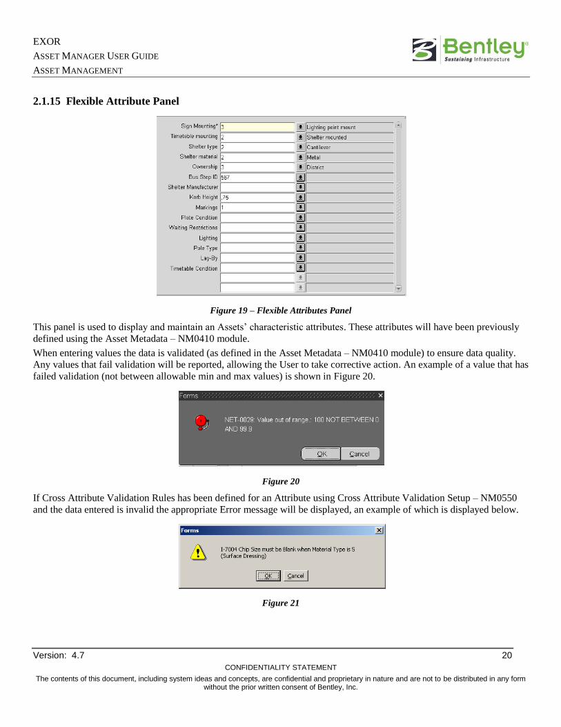
2.1.15 Flexible Attribute Panel
Figure 19 – Flexible Attributes Panel
This panel is used to display and maintain an Assets’ characteristic attributes. These attributes will have been previously
defined using the Asset Metadata – NM0410 module.
When entering values the data is validated (as defined in the Asset Metadata – NM0410 module) to ensure data quality.
Any values that fail validation will be reported, allowing the User to take corrective action. An example of a value that has
failed validation (not between allowable min and max values) is shown in Figure 20.
Figure 20
If Cross Attribute Validation Rules has been defined for an Attribute using Cross Attribute Validation Setup – NM0550
and the data entered is invalid the appropriate Error message will be displayed, an example of which is displayed below.
Figure 21

EXOR
ASSET MANAGER USER GUIDE
ASSET MANAGEMENT
Version: 4.7 21
CONFIDENTIALITY STATEMENT
The contents of this document, including system ideas and concepts, are confidential and proprietary in nature and are not to be distributed in any form without the prior written consent of Bentley, Inc.
2.1.16 Querying Exists Assets
Existing Assets may be queried using any combination of their characteristic Attributes and/or Location. Assets of a
particular types can be queried by using the Asset Type code or individual Assets can be queried using their description,
XSP or primary key value for example. Using the [Advanced Query] option Users may query Assets based upon the
criteria from a saved Parameter Based Inquiry (PBI) (page 190) or may choose individual Assets Types as required.
If the query is driven by location, and a Linear Group or Route is selected, a filter may be applied to restrict the query to
only those Assets which are located either wholly or partially within the specified extent on the selected Route. Figure 22
shows an example of a location-based query that has been restricted to the first 250 metres of a linear Group.
Figure 22
The results of the query are depicted in Figure 23. Assets A, B, D and E would be included within the query as they are
either wholly or partially located within the selected Extent. Assets C and F would not be included as these are located
outside the selected extent.
Figure 23
Note: An offset range can only be applied when the selected location is a linear group, i.e., not a Datum Element or non-
linear group.
For full details of restricting a query by Asset Location refer to page 5.
To query Assets the form must be in Query mode. To do this press the [Enter Query] button on the menu toolbar or
press the F7 hotkey.
EXOR
ASSET MANAGER USER GUIDE
ASSET MANAGEMENT
Version: 4.7 22
CONFIDENTIALITY STATEMENT
The contents of this document, including system ideas and concepts, are confidential and proprietary in nature and are not to be distributed in any form without the prior written consent of Bentley, Inc.
Any combination of the following fields may be used as query criteria directly on the form:
Asset Type (List of Values available)
Asset Description
Asset XSP (List of Values available)
Primary key
Admin Unit
Start Date
To run the query, press the [Execute Query] button on the menu toolbar or press the F8 hotkey.
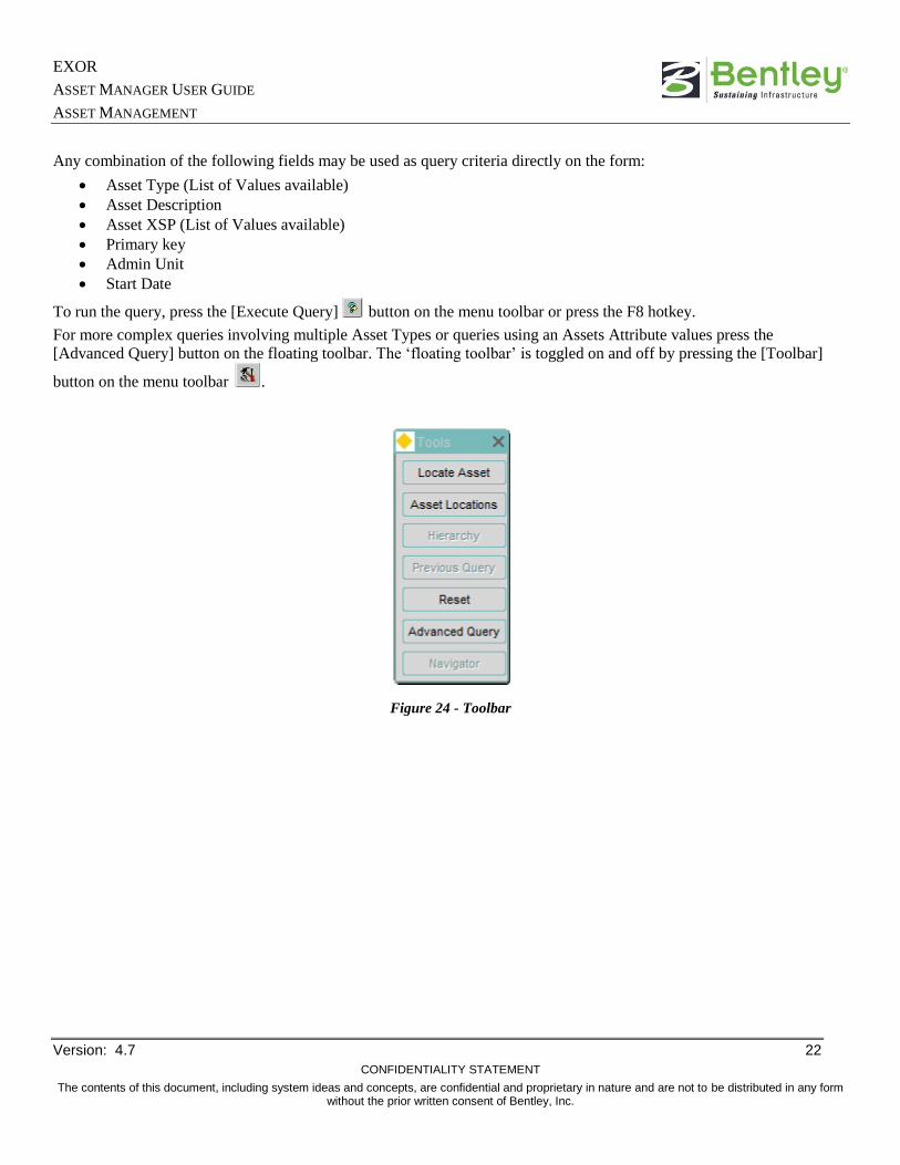
For more complex queries involving multiple Asset Types or queries using an Assets Attribute values press the
[Advanced Query] button on the floating toolbar. The ‘floating toolbar’ is toggled on and off by pressing the [Toolbar]
button on the menu toolbar .
Figure 24 - Toolbar
EXOR
ASSET MANAGER USER GUIDE
ASSET MANAGEMENT
Version: 4.7 23
CONFIDENTIALITY STATEMENT
The contents of this document, including system ideas and concepts, are confidential and proprietary in nature and are not to be distributed in any form without the prior written consent of Bentley, Inc.
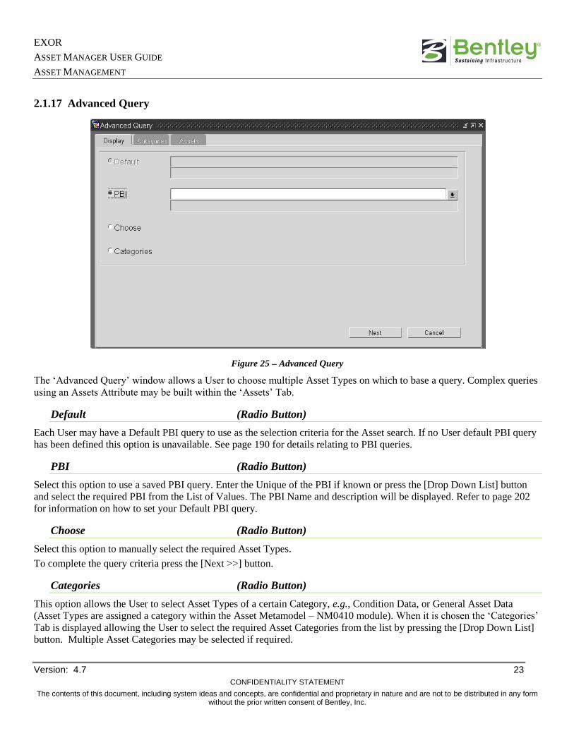
2.1.17 Advanced Query
Figure 25 – Advanced Query
The ‘Advanced Query’ window allows a User to choose multiple Asset Types on which to base a query. Complex queries
using an Assets Attribute may be built within the ‘Assets’ Tab.
Default (Radio Button)
Each User may have a Default PBI query to use as the selection criteria for the Asset search. If no User default PBI query
has been defined this option is unavailable. See page 190 for details relating to PBI queries.
PBI (Radio Button)
Select this option to use a saved PBI query. Enter the Unique of the PBI if known or press the [Drop Down List] button
and select the required PBI from the List of Values. The PBI Name and description will be displayed. Refer to page 202
for information on how to set your Default PBI query.
Choose (Radio Button)
Select this option to manually select the required Asset Types.
To complete the query criteria press the [Next >>] button.
Categories (Radio Button)
This option allows the User to select Asset Types of a certain Category, e.g., Condition Data, or General Asset Data
(Asset Types are assigned a category within the Asset Metamodel – NM0410 module). When it is chosen the ‘Categories’
Tab is displayed allowing the User to select the required Asset Categories from the list by pressing the [Drop Down List]
button. Multiple Asset Categories may be selected if required.

EXOR
ASSET MANAGER USER GUIDE
ASSET MANAGEMENT
Version: 4.7 24
CONFIDENTIALITY STATEMENT
The contents of this document, including system ideas and concepts, are confidential and proprietary in nature and are not to be distributed in any form without the prior written consent of Bentley, Inc.
Figure 26 - Categories
To complete the query criteria press the [Next >>] button. All Asset Types, to which the User has Role based access, of
the selected category(s) will be displayed within the ‘Assets’ panel (Figure 27).

EXOR
ASSET MANAGER USER GUIDE
ASSET MANAGEMENT
Version: 4.7 25
CONFIDENTIALITY STATEMENT
The contents of this document, including system ideas and concepts, are confidential and proprietary in nature and are not to be distributed in any form without the prior written consent of Bentley, Inc.
2.1.18 Assets (Defining Query Types)
Figure 27 - Assets
This panel allows the required Asset Types to be entered along with any attribute criteria to be used within the Asset
Query. If either the 'Default' or 'PBI' options have been selected a copy of the PBI Query definition will be displayed. This
may be amended if required without affecting the original PBI query.
If the Asset ‘Categories’ option has been selected all Asset Types, to which the User has Role based access, of the
selected category(s) will be displayed.
To remove any unwanted Asset Types from the query, select the unwanted Type and press the [Delete Record] button
on the menu toolbar.
When applying an attribute-based filter to an Asset Type each Type may be queried on a single Attribute and value or
Multiple Attribute and value combinations. If multiple Attributes are selected the relationship between the Attributes may
be defined as an 'AND' or 'OR' relationship. Attribute criteria may also be nested with 5 levels of nesting available if
required.
BS Bus Stop
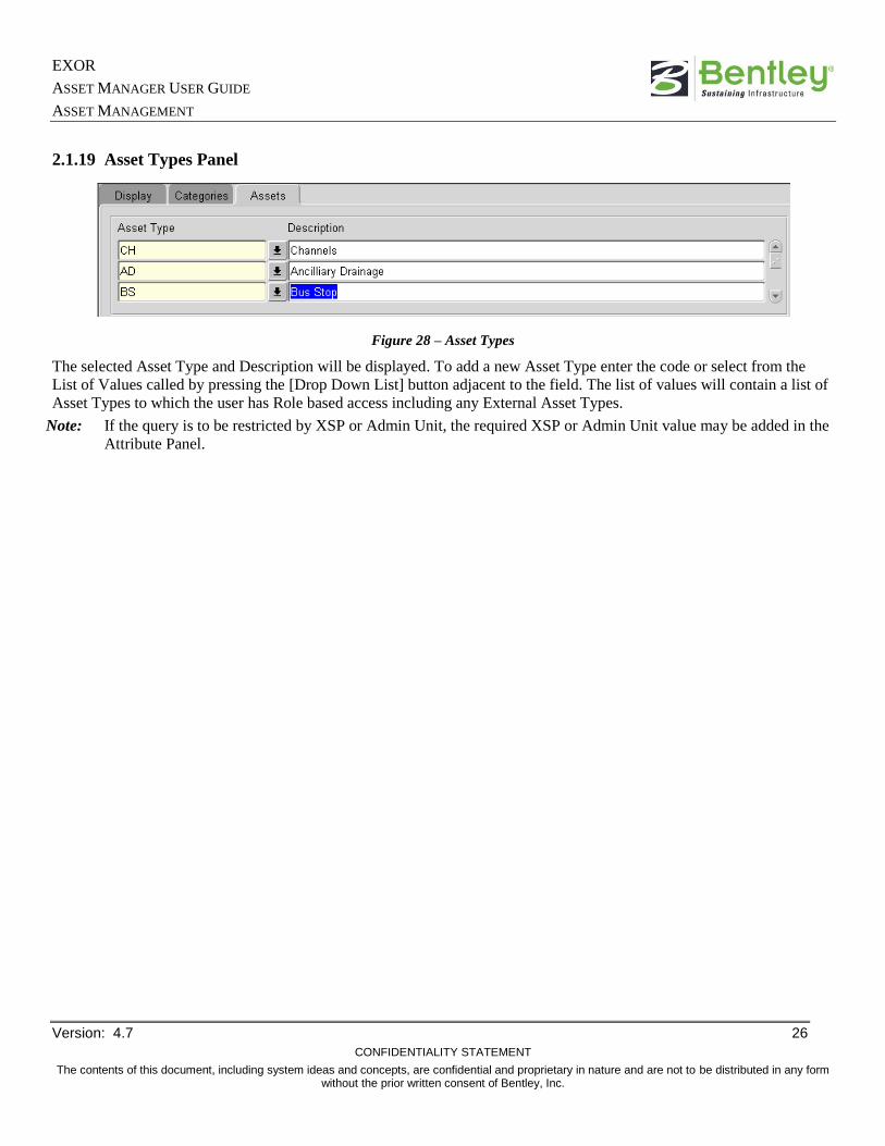
EXOR
ASSET MANAGER USER GUIDE
ASSET MANAGEMENT
Version: 4.7 26
CONFIDENTIALITY STATEMENT
The contents of this document, including system ideas and concepts, are confidential and proprietary in nature and are not to be distributed in any form without the prior written consent of Bentley, Inc.
2.1.19 Asset Types Panel
Figure 28 – Asset Types
The selected Asset Type and Description will be displayed. To add a new Asset Type enter the code or select from the
List of Values called by pressing the [Drop Down List] button adjacent to the field. The list of values will contain a list of
Asset Types to which the user has Role based access including any External Asset Types.
Note: If the query is to be restricted by XSP or Admin Unit, the required XSP or Admin Unit value may be added in the
Attribute Panel.
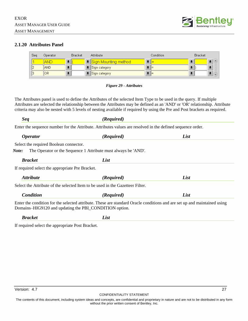
EXOR
ASSET MANAGER USER GUIDE
ASSET MANAGEMENT
Version: 4.7 27
CONFIDENTIALITY STATEMENT
The contents of this document, including system ideas and concepts, are confidential and proprietary in nature and are not to be distributed in any form without the prior written consent of Bentley, Inc.
2.1.20 Attributes Panel
Figure 29 - Attributes
The Attributes panel is used to define the Attributes of the selected Item Type to be used in the query. If multiple
Attributes are selected the relationship between the Attributes may be defined as an 'AND' or 'OR' relationship. Attribute
criteria may also be nested with 5 levels of nesting available if required by using the Pre and Post brackets as required.
Seq (Required)
Enter the sequence number for the Attribute. Attributes values are resolved in the defined sequence order.
Operator (Required) List
Select the required Boolean connector.
Note: The Operator or the Sequence 1 Attribute must always be 'AND'.
Bracket List
If required select the appropriate Pre Bracket.
Attribute (Required) List
Select the Attribute of the selected Item to be used in the Gazetteer Filter.
Condition (Required) List
Enter the condition for the selected attribute. These are standard Oracle conditions and are set up and maintained using
Domains–HIG9120 and updating the PBI_CONDITION option.
Bracket List
If required select the appropriate Post Bracket.

EXOR
ASSET MANAGER USER GUIDE
ASSET MANAGEMENT
Version: 4.7 28
CONFIDENTIALITY STATEMENT
The contents of this document, including system ideas and concepts, are confidential and proprietary in nature and are not to be distributed in any form without the prior written consent of Bentley, Inc.
2.1.21 Values Panel
Figure 30 - Values
This panel is used to define the parameter values for the currently selected Attribute.
Value (Required) (List)
Enter the required ‘Query’ value for the currently selected Attribute. If the attribute values are held in a Domain, the List
of Values may be called and the description of the selected value will be displayed. If the ‘Condition’ entered for the
Attribute is ‘BETWEEN’ enter the second value in the field below.
If a List of Values is called the extended LOV window will be called as shown in Figure 31.
Figure 31 – Extended LOV
This list will display the Domain Lookup Values and Descriptions associated with the selected Attribute.
The Display of the available Values may be ordered by the Lookup Value or by the Description by pressing the [Value]
button or the [Meaning] button respectively.
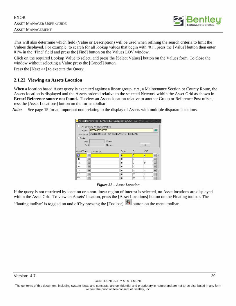
EXOR
ASSET MANAGER USER GUIDE
ASSET MANAGEMENT
Version: 4.7 29
CONFIDENTIALITY STATEMENT
The contents of this document, including system ideas and concepts, are confidential and proprietary in nature and are not to be distributed in any form without the prior written consent of Bentley, Inc.
This will also determine which field (Value or Description) will be used when refining the search criteria to limit the
Values displayed. For example, to search for all lookup values that begin with ‘01’, press the [Value] button then enter
01% in the ‘Find’ field and press the [Find] button on the Values LOV window.
Click on the required Lookup Value to select, and press the [Select Values] button on the Values form. To close the
window without selecting a Value press the [Cancel] button.
Press the [Next >>] to execute the Query.
2.1.22 Viewing an Assets Location
When a location based Asset query is executed against a linear group, e.g., a Maintenance Section or County Route, the
Assets location is displayed and the Assets ordered relative to the selected Network within the Asset Grid as shown in
Error! Reference source not found.. To view an Assets location relative to another Group or Reference Post offset,
ress the [Asset Locations] button on the forms toolbar.
Note: See page 15 for an important note relating to the display of Assets with multiple disparate locations.
Figure 32 – Asset Location
If the query is not restricted by location or a non-linear region of interest is selected, no Asset locations are displayed
within the Asset Grid. To view an Assets’ location, press the [Asset Locations] button on the Floating toolbar. The
‘floating toolbar’ is toggled on and off by pressing the [Toolbar] button on the menu toolbar.

EXOR
ASSET MANAGER USER GUIDE
ASSET MANAGEMENT
Version: 4.7 30
CONFIDENTIALITY STATEMENT
The contents of this document, including system ideas and concepts, are confidential and proprietary in nature and are not to be distributed in any form without the prior written consent of Bentley, Inc.
Figure 33
For full details on viewing Asset Locations see page 46.

EXOR
ASSET MANAGER USER GUIDE
ASSET MANAGEMENT
Version: 4.7 31
CONFIDENTIALITY STATEMENT
The contents of this document, including system ideas and concepts, are confidential and proprietary in nature and are not to be distributed in any form without the prior written consent of Bentley, Inc.
2.1.23 Locate/Relocate or Append a Location to an Asset
An existing Asset can be located/relocated using the [Locate Asset] (Error! Reference source not found.) option
vailable on the floating toolbar. The ‘floating toolbar’ is toggled on and off by pressing the [Toolbar] button on the
menu toolbar. This option can be used to change the location of an existing Asset or locate an Asset that is currently un-
located.
Figure 34 – Locate/relocate
Assets may be located on a Network, relative to any Linear Group that contains the appropriate base Datum Network
Elements or on appropriate Datum Elements. This could include an Inspection Route, State Highway, Abnormal Load
Movement Route, etc.
When an Asset Item is located the system will check if the Item already has a Network location. If this is the case the User
will be prompted to either ‘Append’ the new location to the existing or replace the existing location with the newly
defined location.

EXOR
ASSET MANAGER USER GUIDE
ASSET MANAGEMENT
Version: 4.7 32
CONFIDENTIALITY STATEMENT
The contents of this document, including system ideas and concepts, are confidential and proprietary in nature and are not to be distributed in any form without the prior written consent of Bentley, Inc.
Figure 35
Note: The Asset Item Type must have the ‘Multiple Allowed’ flag selected in the Asset Metamodel – NM0410 module
in order to have more than one location record.
2.1.24 Route Panel
Network Gaz
Enter the name of the Linear Group/Section or Datum on which the Asset is located or select from the Gazetteer.
2.1.25 Sub Class Panel
Any ambiguous Linear References supplied may be automatically resolved by specifying the Network Type Subclass on
which to locate the Asset. If the Network Type Subclass is unspecified and an ambiguous reference is supplied a List of
Values will be supplied from which the User must select the required Network Element.
The Start and End Route Offset measures for the Asset can be entered relative to various methods using the Extent Limits
form that is called by pressing the [Edit Location…] button (see page 34).
2.1.26 Start Panel
This panel is used enter/display the start offset of the Asset.
Intersection Display Only
If the start offset has been defined relative to a Node along the selected Route using the extent limits window, the Node
name will be displayed.
Section Display Only
If the start offset has been defined relative to a Datum element using the extent limits window, the Datum Name of
relative offset will be displayed.
Route Offset
Enter the Start Offset of the Asset relative to the selected Network. If the start offset has been defined using the extent
limits window the Start Offset will be automatically displayed.

EXOR
ASSET MANAGER USER GUIDE
ASSET MANAGEMENT
Version: 4.7 33
CONFIDENTIALITY STATEMENT
The contents of this document, including system ideas and concepts, are confidential and proprietary in nature and are not to be distributed in any form without the prior written consent of Bentley, Inc.
2.1.27 End Panel
This panel is used enter/display the end offset of the Asset for continuous Assets (this panel is disabled for Point Items).
Intersection Display Only
If the end offset has been defined relative to a Node along the selected Route using the extent limits window, the Node
name will be displayed.
Section Display Only
If the end offset has been defined relative to a Datum element using the extent limits window, the Datum Name of relative
offset will be displayed.
Route Offset
Enter the end Offset of the Asset relative to the selected Network. If the end offset has been defined using the extent limits
window the end Offset will be automatically displayed.
Effective Date (Required, Default)
Enter the effective date of the Asset Location. This may be a different date than the effective date of the Asset, but may
not precede the Asset Start Date.
To Locate the Asset Item press the [Locate] button.
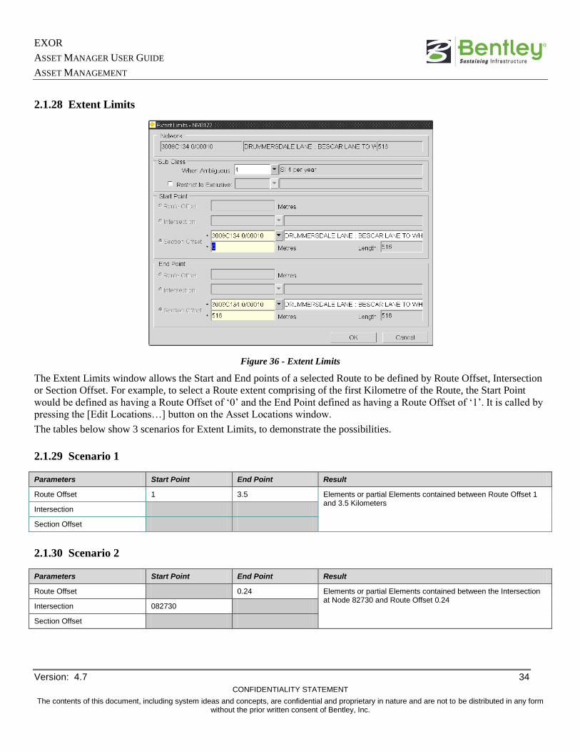
EXOR
ASSET MANAGER USER GUIDE
ASSET MANAGEMENT
Version: 4.7 34
CONFIDENTIALITY STATEMENT
The contents of this document, including system ideas and concepts, are confidential and proprietary in nature and are not to be distributed in any form without the prior written consent of Bentley, Inc.
2.1.28 Extent Limits
Figure 36 - Extent Limits
The Extent Limits window allows the Start and End points of a selected Route to be defined by Route Offset, Intersection
or Section Offset. For example, to select a Route extent comprising of the first Kilometre of the Route, the Start Point
would be defined as having a Route Offset of ‘0’ and the End Point defined as having a Route Offset of ‘1’. It is called by
pressing the [Edit Locations…] button on the Asset Locations window.
The tables below show 3 scenarios for Extent Limits, to demonstrate the possibilities.
2.1.29 Scenario 1
Parameters Start Point End Point Result
Route Offset 1 3.5 Elements or partial Elements contained between Route Offset 1 and 3.5 Kilometers
Intersection
Section Offset
2.1.30 Scenario 2
Parameters Start Point End Point Result
Route Offset 0.24 Elements or partial Elements contained between the Intersection at Node 82730 and Route Offset 0.24
Intersection 082730
Section Offset

EXOR
ASSET MANAGER USER GUIDE
ASSET MANAGEMENT
Version: 4.7 35
CONFIDENTIALITY STATEMENT
The contents of this document, including system ideas and concepts, are confidential and proprietary in nature and are not to be distributed in any form without the prior written consent of Bentley, Inc.
2.1.31 Scenario 3
Parameters Start Point End Point Result
Route Offset 5.6 Elements or partial Element contained between 35m along Element H004/1-S and Route Offset 5.6 Kilometers
Intersection
Section Offset H004/1-S
35
2.1.32 Sub Class
Figure 37 - Subclass
The ‘Sub Class’ panel allows the User to choose the Sub Class of the Elements, within the defined extent limits, on which
to locate the Asset Item. If neither the Sub Class ‘When Ambiguous’ or ‘Restrict to Exclusive’ field are populated, the
Asset Item will be located on Elements of all Sub-Classes within the defined extent limits.
2.1.33 Restrict to Exclusive
An Asset Items location may be restricted to a single ‘Exclusive’ Sub Class by selecting the ‘Restrict to Exclusive’ check
box and entering the required Sub-Class in the adjacent field. This will restrict the Asset Locations to Elements whose
Sub Class match the selected Sub Class.
Consider the example in Figure 38

EXOR
ASSET MANAGER USER GUIDE
ASSET MANAGEMENT
Version: 4.7 36
CONFIDENTIALITY STATEMENT
The contents of this document, including system ideas and concepts, are confidential and proprietary in nature and are not to be distributed in any form without the prior written consent of Bentley, Inc.
Figure 38
The Route displayed above contains a combination of Network Type Subclasses. An item of Asset is to be located within
the extent limits shown, but only where the Network Type Sub Class is ‘L’ – Left.
By selecting the ‘Restrict to Exclusive’ checkbox and entering a value of ‘L’ – left in the adjacent field, the Asset Item
will only be located on Elements (or parts of) with a Network Type Subclass of ‘L’ – Left. Therefore the Asset Location
would include the following Elements:- 3-L,4-L, 8-L, 9-L
2.1.34 Ambiguous References
Any Ambiguous references within the selected extent limits may be automatically resolved by entering the required
Network Type Sub-class in the ‘Subclass’ field.
Consider the example in Figure 39.
Figure 39
The Route displayed above contains a combination of Network Type Subclasses. An item of Asset is to be located within
the extent limits shown, but only where the Network Type Sub Class is either ‘S’ – Single or ‘L’ – Left.
By entering a value of ‘L’ – left in the Sub Class ‘When Ambiguous’ field of the extent limits window, the Asset Item
will only be located on Elements (or parts of) with a Network Type Subclass of ‘S’ – Single and those Elements (or parts

EXOR
ASSET MANAGER USER GUIDE
ASSET MANAGEMENT
Version: 4.7 37
CONFIDENTIALITY STATEMENT
The contents of this document, including system ideas and concepts, are confidential and proprietary in nature and are not to be distributed in any form without the prior written consent of Bentley, Inc.
of) with a Network Type Sub Class of ‘L’ –Left. Therefore the Asset Location would include the following Elements:–1-
S, 2-S, 3-L, 4-L, 5-S, 8-L, 9-L, 12-S
Route (Display Only)
The Unique Route reference description and Route Length will be displayed.
Sub Class When Ambiguous (Optional)
Enter the required Network Element Sub Class for Elements that should be selected if any ambiguity arises.
Sub Class –Restrict to Exclusive (Optional)
Enter the required Network Element Sub Class to which the selection should be restricted.
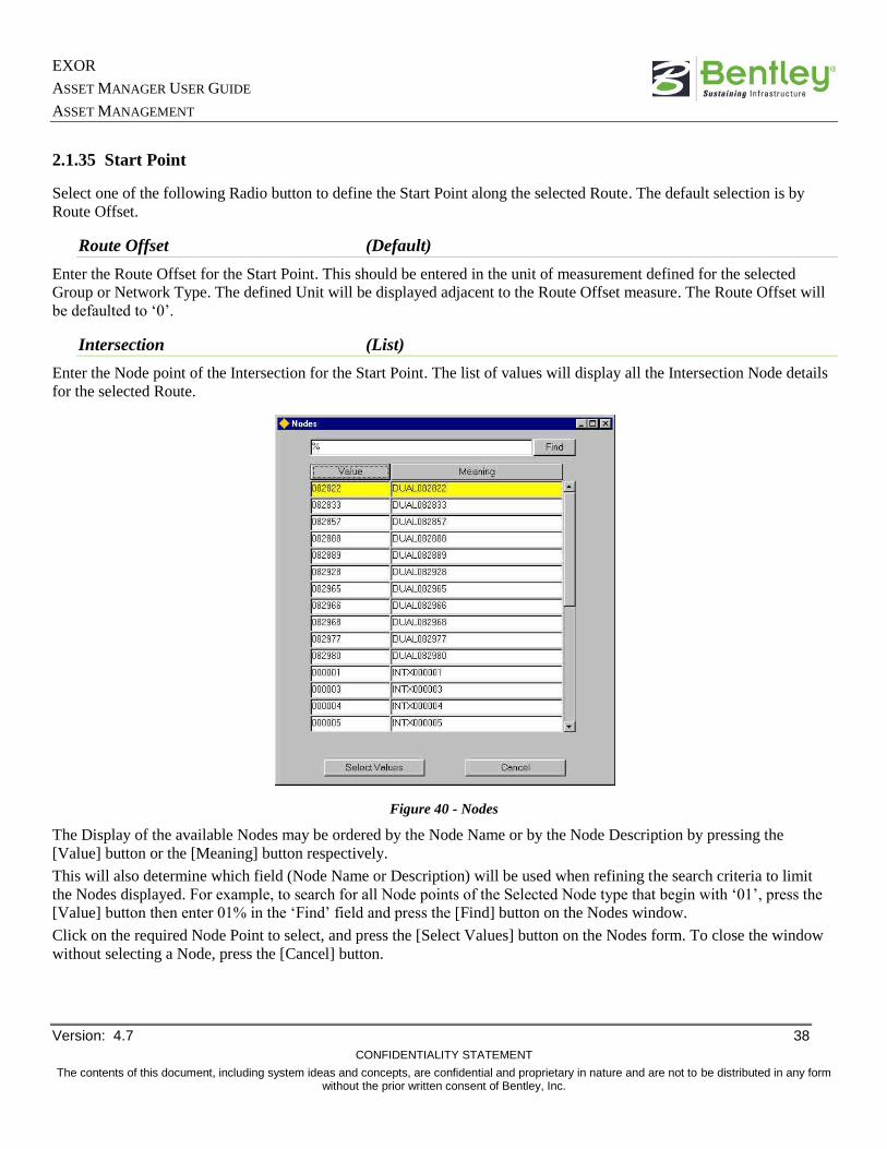
EXOR
ASSET MANAGER USER GUIDE
ASSET MANAGEMENT
Version: 4.7 38
CONFIDENTIALITY STATEMENT
The contents of this document, including system ideas and concepts, are confidential and proprietary in nature and are not to be distributed in any form without the prior written consent of Bentley, Inc.
2.1.35 Start Point
Select one of the following Radio button to define the Start Point along the selected Route. The default selection is by
Route Offset.
Route Offset (Default)
Enter the Route Offset for the Start Point. This should be entered in the unit of measurement defined for the selected
Group or Network Type. The defined Unit will be displayed adjacent to the Route Offset measure. The Route Offset will
be defaulted to ‘0’.
Intersection (List)
Enter the Node point of the Intersection for the Start Point. The list of values will display all the Intersection Node details
for the selected Route.
Figure 40 - Nodes
The Display of the available Nodes may be ordered by the Node Name or by the Node Description by pressing the
[Value] button or the [Meaning] button respectively.
This will also determine which field (Node Name or Description) will be used when refining the search criteria to limit
the Nodes displayed. For example, to search for all Node points of the Selected Node type that begin with ‘01’, press the
[Value] button then enter 01% in the ‘Find’ field and press the [Find] button on the Nodes window.
Click on the required Node Point to select, and press the [Select Values] button on the Nodes form. To close the window
without selecting a Node, press the [Cancel] button.

EXOR
ASSET MANAGER USER GUIDE
ASSET MANAGEMENT
Version: 4.7 39
CONFIDENTIALITY STATEMENT
The contents of this document, including system ideas and concepts, are confidential and proprietary in nature and are not to be distributed in any form without the prior written consent of Bentley, Inc.
Section Offset (List)
Enter the Unique Element reference for the Start Point. The Element description will be displayed in the adjacent field.
The list of values will display all the Network Element within the selected Route.
Enter the Element Offset in the unit of measurement defined for the Datum Element in Network Types–NM0002. The
measured length of the Element will be displayed in the adjacent field.
2.1.36 End Point
Select one of the following Radio button to define the Start Point along the selected Route. The default selection is by
Route Offset
Route Offset (Default)
Enter the Route Offset for the End Point. This should be entered in the unit of measurement defined for the selected
Group or Network Type. The defined Unit will be displayed adjacent to the Route Offset measure. The Route Offset of
the End of the Route will be displayed as the default value.
Intersection (List)
Enter the Node point of the Intersection for the End Point. The list of values will display all the Intersection Node details
for the selected Route.
Section Offset (List)
Enter the Unique Element reference for the End Point. The Element description will be displayed in the adjacent field.
The list of values will display all the Network Element within the selected Route.
Enter the Element Offset in the unit of measurement defined for the Datum Element in Network Types–NM0002. The
measured length of the Element will be displayed in the adjacent field.
The ‘Locate Asset’ window will be displayed and the Extent Limits selected will be displayed as Offset values relative to
the selected Network Type or Group.

EXOR
ASSET MANAGER USER GUIDE
ASSET MANAGEMENT
Version: 4.7 40
CONFIDENTIALITY STATEMENT
The contents of this document, including system ideas and concepts, are confidential and proprietary in nature and are not to be distributed in any form without the prior written consent of Bentley, Inc.
2.1.37 Locate an Asset using a saved Extent
Continuous Assets may be located using a Saved Network Extent (see the Network Manager User Guide). This will place
the Asset on all ‘segments’ of network within the saved extent. Assets may be located on a saved Extent using the ‘Saved
Extent’ tab of the Locate Asset window. This is called by pressing the [Locate Asset] button on the floating toolbar.
Figure 41
The Network Extent used to locate an Item of Continuous Asset may include Elements which a wholly or partially
contained within the extent.
When using a Network Extent to locate Asset Product Option MULTINVRTE must be set to suit your Organisational
Requirements. If this option is set to ‘Y’ the Network Extent may contain Elements from multiple Routes or Groups. If
the Option is set to ‘N’ the Network Extent must contain Elements from within a single Group. If MULTINVRTE is set to
‘N’ and an inappropriate Network Extent is used the message in Figure 42 be displayed.
Figure 42
These need not be connected but ALL the member Elements must be wholly within a Single Network Group, e.g., a
Single Route.
If the selected Network Extent contains Overlaps (i.e., the same extent of network is included more than once within the
Network Extent) the message below will be displayed, preventing the Network Extent be used.
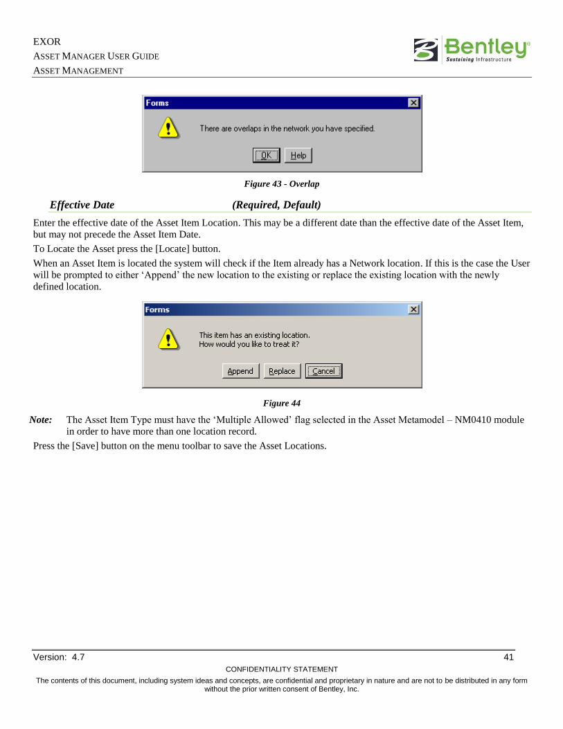
EXOR
ASSET MANAGER USER GUIDE
ASSET MANAGEMENT
Version: 4.7 41
CONFIDENTIALITY STATEMENT
The contents of this document, including system ideas and concepts, are confidential and proprietary in nature and are not to be distributed in any form without the prior written consent of Bentley, Inc.
Figure 43 - Overlap
Effective Date (Required, Default)
Enter the effective date of the Asset Item Location. This may be a different date than the effective date of the Asset Item,
but may not precede the Asset Item Date.
To Locate the Asset press the [Locate] button.
When an Asset Item is located the system will check if the Item already has a Network location. If this is the case the User
will be prompted to either ‘Append’ the new location to the existing or replace the existing location with the newly
defined location.
Figure 44
Note: The Asset Item Type must have the ‘Multiple Allowed’ flag selected in the Asset Metamodel – NM0410 module
in order to have more than one location record.
Press the [Save] button on the menu toolbar to save the Asset Locations.

EXOR
ASSET MANAGER USER GUIDE
ASSET MANAGEMENT
Version: 4.7 42
CONFIDENTIALITY STATEMENT
The contents of this document, including system ideas and concepts, are confidential and proprietary in nature and are not to be distributed in any form without the prior written consent of Bentley, Inc.
2.1.38 Locate an Asset using Reference Post Referencing
Assets may be located relative to the absolute distance from a known reference marker, such as a Route Milepost, using
the ‘Reference Post’ tab of the Locate Asset window (Figure 45). This is called by pressing the [Locate Asset] button on
the floating toolbar.
Figure 45 – Reference Post
Reference Post or ‘Route Mile Post’ referencing, allows the location of an Asset to be expressed relative to the distance
from a known ‘reference’ Asset, located on the selected Route. The ‘Reference’ Asset must be a ‘Point Item’ and can be
either an Asset stored within the Exor database or an External Asset.
The ‘Reference Post Offset’ is always entered relative to the Route cardinality. Therefore a positive distance from a
Reference Post means that the Asset is located further along the Route than the ‘reference Post’, where as a negative
distance means the Asset is located on the Route before the ‘reference post’.
If no reference Item is specified, the Reference Offset is taken as the distance from the Start of the Route.
Consider the example in Figure 46.
Figure 46
Asset ‘A’ could be located in several different ways relative to the Marker Posts (MP) shown in the diagram. Its start
location could be expressed as follows.

EXOR
ASSET MANAGER USER GUIDE
ASSET MANAGEMENT
Version: 4.7 43
CONFIDENTIALITY STATEMENT
The contents of this document, including system ideas and concepts, are confidential and proprietary in nature and are not to be distributed in any form without the prior written consent of Bentley, Inc.
Figure 47
Its end location could be expressed as follows:
Figure 48
Figure 49

EXOR
ASSET MANAGER USER GUIDE
ASSET MANAGEMENT
Version: 4.7 44
CONFIDENTIALITY STATEMENT
The contents of this document, including system ideas and concepts, are confidential and proprietary in nature and are not to be distributed in any form without the prior written consent of Bentley, Inc.
2.1.39 Route Panel
Route Required List, Gaz
Enter the Route on which the Asset is to be located. The Route description will be displayed in the adjacent field.
Start/End
The Min and Max Offsets for Route will be displayed. Only Reference Post Assets, of the selected Type, that are located
between the specified Start and End Offsets will be available for selection when the Start/End Ref post Offsets are
entered. This allows the LOV of Reference Post items to be restricted on long Routes.
2.1.40 Start/End Reference
Figure 50
The Start and End Reference panels are used to specify the start and end locations of an Asset relative to a Reference Post
Item
Note: The End Reference panel is disabled when locating a ‘Point’ Asset.
Type Default List
This is ‘referencing Asset Type’. Any Point Asset Type of categories ‘I’ – General Assets, ‘F’ – External Assets or ‘D’ –
Derived Assets, to which the User has access and which can be located on the selected Route Type, may be chosen. A
default Reference Type can be defined by setting User/product Option DEFITEMTYP to the required Point Asset Type.
Refer to the General User Guide for information on how to define User Options.
Item List
This is the Reference Post item against which the Asset is being located. Only Assets of the selected Type located within
the specified Route Start and End Offsets are available selection. The LOV displays the following details:
Reference Post Asset Description (IIT_DESCR)
Location on the selected Route
For example, MP – 13098652 @ 3.00 Miles
The units displayed are derived from the selected Route.

EXOR
ASSET MANAGER USER GUIDE
ASSET MANAGEMENT
Version: 4.7 45
CONFIDENTIALITY STATEMENT
The contents of this document, including system ideas and concepts, are confidential and proprietary in nature and are not to be distributed in any form without the prior written consent of Bentley, Inc.
Figure 51
If no reference Item is specified, the Reference Offset is taken as the distance from the Start of the Route.
Offset
This is the distance from the selected Reference Post for the Start/End of the Assets. A positive values means that the
Asset is located further along the Route than the Reference Post. A negative value means it is located on the Route before
the ‘reference post’.
Effective Date (Required, Default)
Enter the effective date of the Asset Item Location. This may be a different date than the effective date of the Asset Item,
but may not precede the Asset Item Date.
To Locate the Asset press the [Locate] button.
When an Asset Item is located the system will check if the Item already has a Network location. If this is the case the User
will be prompted to either ‘Append’ the new location to the existing or replace the existing location with the newly
defined location.
Figure 52
Note: The Asset Item Type must have the ‘Multiple Allowed’ flag selected in the Asset Metamodel – NM0410 module
in order to have more than one location record.

EXOR
ASSET MANAGER USER GUIDE
ASSET MANAGEMENT
Version: 4.7 46
CONFIDENTIALITY STATEMENT
The contents of this document, including system ideas and concepts, are confidential and proprietary in nature and are not to be distributed in any form without the prior written consent of Bentley, Inc.
2.1.41 View an Asset Location
An Assets location, relative to the Route(s), Route Mile Post, Datum Elements and Groups (non linear) on which it is
located may be viewed using the Asset Location button on the Floating Toolbar. The ‘floating toolbar’ is toggled on and
off by pressing the [Toolbar] button on the menu toolbar.
Figure 53 - Routes
Figure 54 - Datum
Figure 55 - Groups
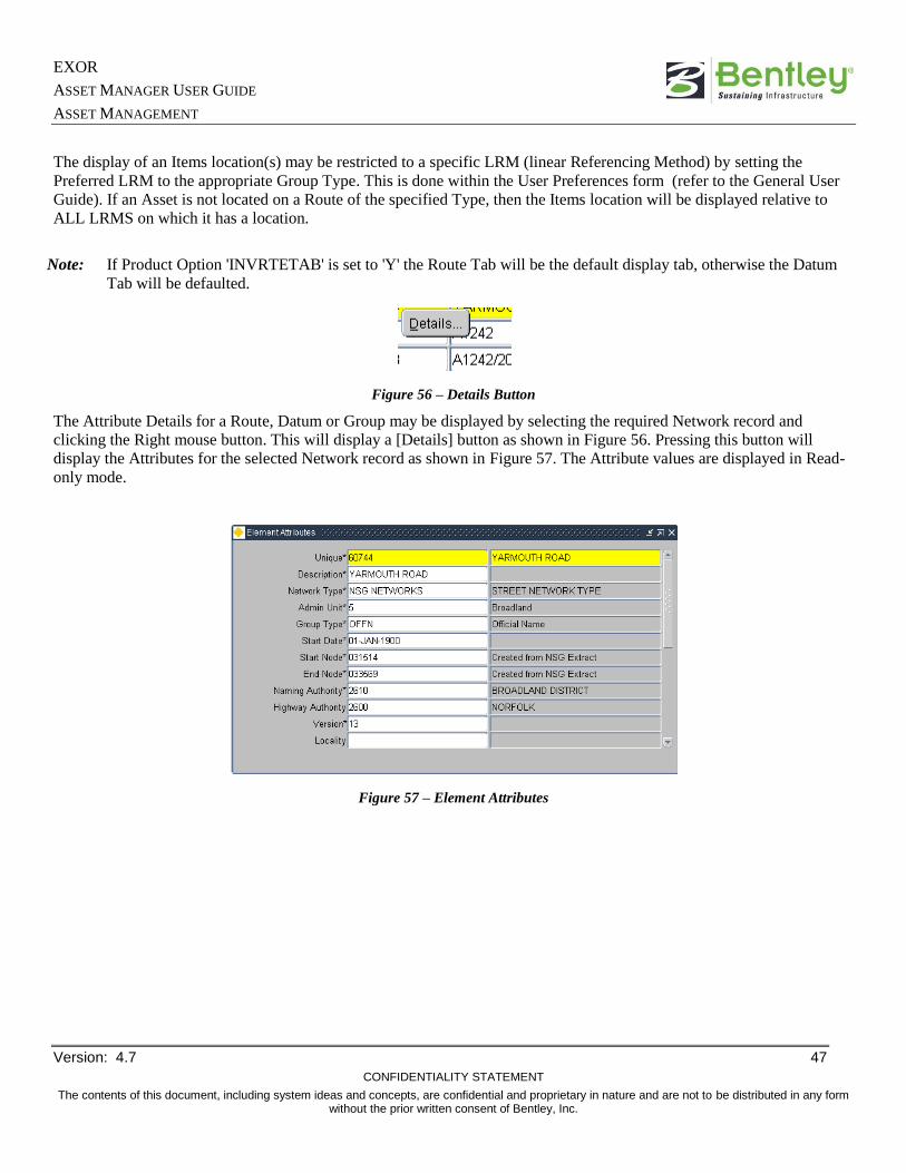
EXOR
ASSET MANAGER USER GUIDE
ASSET MANAGEMENT
Version: 4.7 47
CONFIDENTIALITY STATEMENT
The contents of this document, including system ideas and concepts, are confidential and proprietary in nature and are not to be distributed in any form without the prior written consent of Bentley, Inc.
The display of an Items location(s) may be restricted to a specific LRM (linear Referencing Method) by setting the
Preferred LRM to the appropriate Group Type. This is done within the User Preferences form (refer to the General User
Guide). If an Asset is not located on a Route of the specified Type, then the Items location will be displayed relative to
ALL LRMS on which it has a location.
Note: If Product Option 'INVRTETAB' is set to 'Y' the Route Tab will be the default display tab, otherwise the Datum
Tab will be defaulted.
Figure 56 – Details Button
The Attribute Details for a Route, Datum or Group may be displayed by selecting the required Network record and
clicking the Right mouse button. This will display a [Details] button as shown in Figure 56. Pressing this button will
display the Attributes for the selected Network record as shown in Figure 57. The Attribute values are displayed in Read-
only mode.
Figure 57 – Element Attributes

EXOR
ASSET MANAGER USER GUIDE
ASSET MANAGEMENT
Version: 4.7 48
CONFIDENTIALITY STATEMENT
The contents of this document, including system ideas and concepts, are confidential and proprietary in nature and are not to be distributed in any form without the prior written consent of Bentley, Inc.
2.1.42 Viewing an Asset Location using Reference Post Referencing
Figure 58 – Reference Post Referencing
If Reference Post referencing has been deployed, the location of the selected Asset relative to the nearest preceding
Reference Post will be displayed. If no preceding Reference Post exists the distance to the next Reference Post on the
Route will be displayed. This will be represented as a negative value.
The Reference Post Asset Type used to display the Reference Post Offsets is defined by entering the required Asset Type
for Product or User Option DEFITEMTYP. If a value has been entered in the User Option this will take precedence over
the Product Option value. Refer the General System Admin Guide for further details on Product and User Options.
Start/End Reference Item
The Start and End locations of the currently selected Asset will be displayed relative to the nearest preceding Reference
Post Asset. For point Asset Types the start and end Reference values will be the same.
The following details are displayed:
Reference Post Asset Type
Asset Description (IIT_DESCR)
Distance from preceding Ref Post (or –ve distance to next if no preceding)
Figure 59

EXOR
ASSET MANAGER USER GUIDE
ASSET MANAGEMENT
Version: 4.7 49
CONFIDENTIALITY STATEMENT
The contents of this document, including system ideas and concepts, are confidential and proprietary in nature and are not to be distributed in any form without the prior written consent of Bentley, Inc.
2.1.43 Closing an Asset
An Asset may be closed by entering the required closure or end-date in the ‘End Date’ field. The date may be manually
entered or selected from the calendar.
Figure 60
Closed’ Assets may be viewed by setting the ‘Effective Date’ date in the User Preferences window, to a date when the
Asset was ‘Open’.

EXOR
ASSET MANAGER USER GUIDE
ASSET MANAGEMENT
Version: 4.7 50
CONFIDENTIALITY STATEMENT
The contents of this document, including system ideas and concepts, are confidential and proprietary in nature and are not to be distributed in any form without the prior written consent of Bentley, Inc.
2.1.44 Managing Hierarchical Assets
Asset Hierarchies are created and managed using the ‘Hierarchy’ Window, which is toggled on/off using the [Hierarchy]
button on the floating Toolbar.
Figure 61
When any Asset within a Hierarchy is queried, the entire Asset grouping within which the Asset exists can be displayed
by pressing the [Hierarchy] button. The Asset Type code and Primary Key are displayed. To view the details of any Asset
within the Hierarchy, double click the required record within the Hierarchy Tree. The Asset Maintenance form will be
called recursively and display the details of the selected Asset. To return to the original record set, press the [Previous
Query] button on the floating toolbar.
2.1.45 Creating a new Asset Hierarchy
When creating a new Asset Hierarchy the ‘Top Level’ Asset should be added first in the normal manner within the form.
Once saved, the Asset Type code and Primary key value will be displayed within the Hierarchy browser (toggled on/off
using the [Hierarchy] button on the floating toolbar). To add a ‘child asset’ within the hierarchy, select the relevant ‘parent
Asset’ and press the [Create Child Item] button on the Hierarchy browser window.
Figure 62
The Hierarchy Window will be closed and the cursor focus will be set on the next available row within the Asset Grid
awaiting the Child Asset Type to be selected. The List of allowable Assets Types will be restricted to those types defined
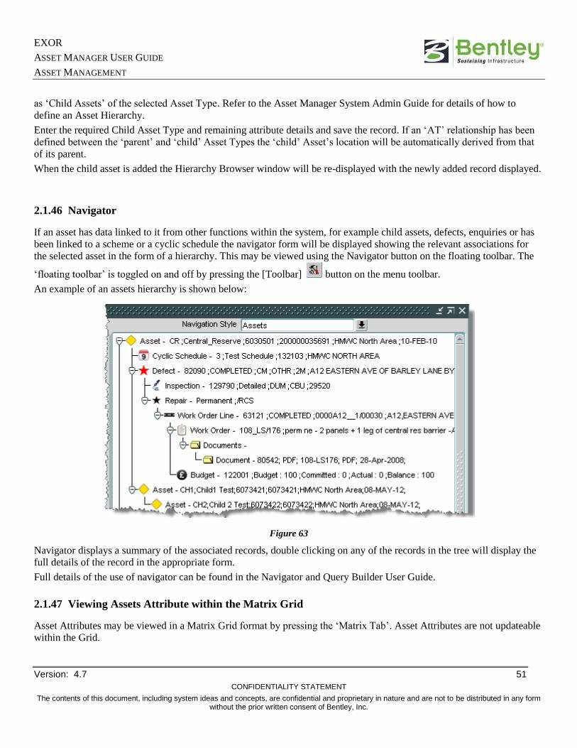
EXOR
ASSET MANAGER USER GUIDE
ASSET MANAGEMENT
Version: 4.7 51
CONFIDENTIALITY STATEMENT
The contents of this document, including system ideas and concepts, are confidential and proprietary in nature and are not to be distributed in any form without the prior written consent of Bentley, Inc.
as ‘Child Assets’ of the selected Asset Type. Refer to the Asset Manager System Admin Guide for details of how to
define an Asset Hierarchy.
Enter the required Child Asset Type and remaining attribute details and save the record. If an ‘AT’ relationship has been
defined between the ‘parent’ and ‘child’ Asset Types the ‘child’ Asset’s location will be automatically derived from that
of its parent.
When the child asset is added the Hierarchy Browser window will be re-displayed with the newly added record displayed.
2.1.46 Navigator
If an asset has data linked to it from other functions within the system, for example child assets, defects, enquiries or has
been linked to a scheme or a cyclic schedule the navigator form will be displayed showing the relevant associations for
the selected asset in the form of a hierarchy. This may be viewed using the Navigator button on the floating toolbar. The
‘floating toolbar’ is toggled on and off by pressing the [Toolbar] button on the menu toolbar.
An example of an assets hierarchy is shown below:
Figure 63
Navigator displays a summary of the associated records, double clicking on any of the records in the tree will display the
full details of the record in the appropriate form.
Full details of the use of navigator can be found in the Navigator and Query Builder User Guide.
2.1.47 Viewing Assets Attribute within the Matrix Grid
Asset Attributes may be viewed in a Matrix Grid format by pressing the ‘Matrix Tab’. Asset Attributes are not updateable
within the Grid.

EXOR
ASSET MANAGER USER GUIDE
ASSET MANAGEMENT
Version: 4.7 52
CONFIDENTIALITY STATEMENT
The contents of this document, including system ideas and concepts, are confidential and proprietary in nature and are not to be distributed in any form without the prior written consent of Bentley, Inc.
Figure 64 – Matrix Grid
The Matrix is useful when Assets such as Footway or Roadway are queried using a Linear Route or Section. It allows the
user to scan through the grid to see where the Road Width value changes for example, as the Assets are ordered in
ascending Offset order. An example is shown in Figure 65.

EXOR
ASSET MANAGER USER GUIDE
ASSET MANAGEMENT
Version: 4.7 53
CONFIDENTIALITY STATEMENT
The contents of this document, including system ideas and concepts, are confidential and proprietary in nature and are not to be distributed in any form without the prior written consent of Bentley, Inc.
Figure 65 – Order Assets
Hint text is available to display the Attribute Name by hovering over an Attribute value. The Hint text displayed is that of
the currently selected Asset within the left hand grid. The example below shows the Hint Text for column 2, which is the
‘Surface Code’ attribute as the selected Asset is a VG – verge.
Figure 66 – Hint Text

EXOR
ASSET MANAGER USER GUIDE
ASSET MANAGEMENT
Version: 4.7 54
CONFIDENTIALITY STATEMENT
The contents of this document, including system ideas and concepts, are confidential and proprietary in nature and are not to be distributed in any form without the prior written consent of Bentley, Inc.
2.1.48 Viewing an Asset on the Map
Assets with a spatial representation may be viewed on the map by pressing the [Show Map] button on the menu toolbar.
Figure 67 shows an example where a Bridge has been queried and its attributes displayed.
Figure 67 – Show Map
If the selected Asset Type has multiple Themes, a list will be displayed (Figure 68) from which the required Theme may
be selected. Highlight the required Theme and press the [Select Values] button.
Figure 68 – Theme Selection
The Map tab will be made active and the map will zoom and centre on the selected feature (Figure 69). The selected
Theme will automatically be made the Active Layer. This allows Enquiries, Defects etc to be raised against the Asset
directly from the Asset Maintenance Map window.
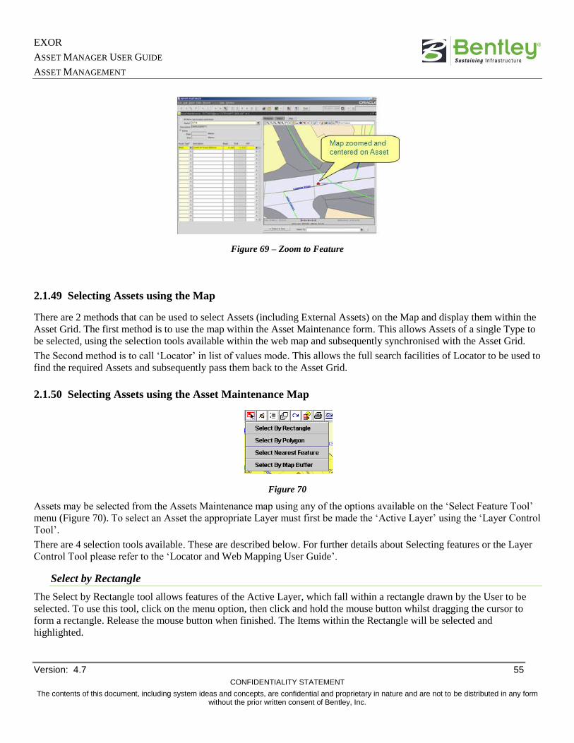
EXOR
ASSET MANAGER USER GUIDE
ASSET MANAGEMENT
Version: 4.7 55
CONFIDENTIALITY STATEMENT
The contents of this document, including system ideas and concepts, are confidential and proprietary in nature and are not to be distributed in any form without the prior written consent of Bentley, Inc.
Figure 69 – Zoom to Feature
2.1.49 Selecting Assets using the Map
There are 2 methods that can be used to select Assets (including External Assets) on the Map and display them within the
Asset Grid. The first method is to use the map within the Asset Maintenance form. This allows Assets of a single Type to
be selected, using the selection tools available within the web map and subsequently synchronised with the Asset Grid.
The Second method is to call ‘Locator’ in list of values mode. This allows the full search facilities of Locator to be used to
find the required Assets and subsequently pass them back to the Asset Grid.
2.1.50 Selecting Assets using the Asset Maintenance Map
Figure 70
Assets may be selected from the Assets Maintenance map using any of the options available on the ‘Select Feature Tool’
menu (Figure 70). To select an Asset the appropriate Layer must first be made the ‘Active Layer’ using the ‘Layer Control
Tool’.
There are 4 selection tools available. These are described below. For further details about Selecting features or the Layer
Control Tool please refer to the ‘Locator and Web Mapping User Guide’.
Select by Rectangle
The Select by Rectangle tool allows features of the Active Layer, which fall within a rectangle drawn by the User to be
selected. To use this tool, click on the menu option, then click and hold the mouse button whilst dragging the cursor to
form a rectangle. Release the mouse button when finished. The Items within the Rectangle will be selected and
highlighted.

EXOR
ASSET MANAGER USER GUIDE
ASSET MANAGEMENT
Version: 4.7 56
CONFIDENTIALITY STATEMENT
The contents of this document, including system ideas and concepts, are confidential and proprietary in nature and are not to be distributed in any form without the prior written consent of Bentley, Inc.
Select by Polygon
The Select by Polygon tool allows features of the Active Layer, which fall within a polygon drawn by the User to be
selected. To use this tool, click on the menu option, and then digitise the polygon’s vertices. Double clicking will
automatically close the polygon. The Items within the Polygon will be selected and highlighted.
Select Nearest Feature
The Select Nearest Feature tool allows the nearest feature to position the User clicks on of the Active Layer to be selected.
To use this tool click on the menu option, then click on the required position on the map. The nearest feature of the Active
Layer will be selected and highlighted.
Select By Map Buffer
The Select by Map Buffer tool allows features of the Active Layer, which fall within a Buffer created using the ‘Show
Buffer Area’ tool.
When using the ‘Select by Rectangle’, ‘Select by Polygon’ or ‘Select By map Buffer’ selection methods, the number of
records selected will be displayed in a dialogue, as shown in Figure 71, allowing the User to confirm their selection.

EXOR
ASSET MANAGER USER GUIDE
ASSET MANAGEMENT
Version: 4.7 57
CONFIDENTIALITY STATEMENT
The contents of this document, including system ideas and concepts, are confidential and proprietary in nature and are not to be distributed in any form without the prior written consent of Bentley, Inc.
Figure 71 – Select by map Buffer
To confirm the selection press [OK]. To synchronize the Asset Maintenance Grid with the selected features within the
map, press the [<< Select to Grid] button. The Assets details currently displayed will be cleared and the Grid will be
synchronised with the features selected within the map. The ‘Attributes’ will also be made Active to allow the Asset
Attributes to be displayed or maintained. Figure 72 shows the grid synchronised with the features selected in Figure 71.
Figure 72 – Asset Grid

EXOR
ASSET MANAGER USER GUIDE
ASSET MANAGEMENT
Version: 4.7 58
CONFIDENTIALITY STATEMENT
The contents of this document, including system ideas and concepts, are confidential and proprietary in nature and are not to be distributed in any form without the prior written consent of Bentley, Inc.
2.1.51 Selecting Assets Using Locator as a List Of Values
The full search and selection functionality available within Locator may be used to select Assets (including External
Assets) by calling Locator in ‘List of Values’ Mode. This is done using the [Find] button on the Exor menu toolbar.
Note: The [Find] button is only available when the form is in Query mode.
Tip: Enter the Asset Type code you wish to search for before pressing the [Find] button. The selected Asset Type
will be displayed as the default ‘Search For’ Asset Type within Locator
Figure 73
When the [Find Asset] button is pressed the Locator module (see the Locator and Web Mapping User Guide for full
details) is called allowing the User to search for the required Assets. Once the required Assets have been selected, press
the [OK] button on the Locator form.
Figure 74

EXOR
ASSET MANAGER USER GUIDE
ASSET MANAGEMENT
Version: 4.7 59
CONFIDENTIALITY STATEMENT
The contents of this document, including system ideas and concepts, are confidential and proprietary in nature and are not to be distributed in any form without the prior written consent of Bentley, Inc.
Figure 75

EXOR
ASSET MANAGER USER GUIDE
ASSET MANAGEMENT
Version: 4.7 60
CONFIDENTIALITY STATEMENT
The contents of this document, including system ideas and concepts, are confidential and proprietary in nature and are not to be distributed in any form without the prior written consent of Bentley, Inc.
2.2 Asset Items – NM0510
Figure 76 - Asset Items Menu Option
This module is used to enter new, modify existing or End-Date (close) existing items of Asset.
Note: Asset Items may also be ‘End Dated’ by some Network Operations and when adding ‘Exclusive’ Asset Types.
This form allows individual Asset items to be entered or the defining characteristics of the Asset item held as ‘flexible
attributes’ to be maintained. Cross Attribute Validation may also be imposed by defining the appropriate rules in NM0550
– Cross Attribute Validation Setup (see the Asset Manager Admin Guide).
Asset Items that are ‘End-Dated’ are NOT deleted from the Exor database; instead they are ‘hidden’ from normal display.
Closed Asset Items may be viewed by setting the ‘Effective Date’ in the User preferences window to a point in time when
the required Asset Item was not End-Dated
Asset Locations are maintained using the Location button on the floating toolbar and are displayed relative to the Route(s)
(linear Groups), Groups (non-linear Groups) and Datum Elements on which the Asset is placed on the Route, Datum and
Group Tabs respectively. A single Asset Item may span multiple Routes or Groups. The location(s) of an Asset Item will
be displayed relative to all Linear Groups on which the Item is located or if a Preferred LRM (Linear Referencing
Method) has been defined the location(s) will only be displayed relative to that LRM.
Any changes made to the location of an Asset Item after it has been entered into the Exor database are recorded and may
be reported on to provide an audit trail of the Asset location changes.
An Item of Asset may be copied and subsequently located on a piece of Network using the [C] copy Asset button on the
Floating Toolbar.
Note: A User flagged as ‘Unrestricted’ in the Users–HIG1832 will have Access to all Asset Items. Items which the
'Unrestricted' User has no specific Admin Unit or Roles based access will be available in READONLY mode.

EXOR
ASSET MANAGER USER GUIDE
ASSET MANAGEMENT
Version: 4.7 61
CONFIDENTIALITY STATEMENT
The contents of this document, including system ideas and concepts, are confidential and proprietary in nature and are not to be distributed in any form without the prior written consent of Bentley, Inc.
2.2.1 Asset Items
Figure 77 - Asset Items
When you enter this panel the cursor sits in the ‘Type’ window waiting for you to either query back existing Asset Items
or to add a new Asset Item. Existing Asset Items may be queried back by using the Gazetteer to select a Network
Grouping or Network Extent or by Standard Query Techniques using any of the ‘Type’, ‘Description’, ‘XSP’, or ‘Primary
key’ fields.
Note: If Product Option 'SHOWINVPK' is set to 'N', the Primary Key Column will not be displayed except when the
form is in Enter Query Mode. Individual User may 'override' this Product Option by setting User Option
'SHOWINVPK' to 'Y'. In this case the User Option will have precedence over the Product Option.
If the Gazetteer is used, all subsequent Asset queries will be restricted to the Network Group or Network Extent selected.
To clear the ‘buffer’ and allow full Querying capabilities press the [Reset Query] button on the form.
To create a new Asset Item press the [Create Record] button on the menu toolbar (or press F6).
Type (Required) List
Enter the Asset Type code. If User Role based security has been implemented on Asset Types, the list of values will only
display the Asset Types applicable to the current User. The Asset Type Description will be displayed in the ‘Attributes’
window in the ‘Type’ field.
Asset Types will have been previously defined using Asset Types–NM0410.
Description (Optional)
Enter a description for the Asset Item. A maximum of 40 characters is allowed.

EXOR
ASSET MANAGER USER GUIDE
ASSET MANAGEMENT
Version: 4.7 62
CONFIDENTIALITY STATEMENT
The contents of this document, including system ideas and concepts, are confidential and proprietary in nature and are not to be distributed in any form without the prior written consent of Bentley, Inc.
XSP (Optional) (List)
Enter the cross sectional position of the Asset Item. The XSP Description for the Asset Type will be displayed in the
‘Attributes’ window in the ‘XSP’ field. The XSP description for the Asset Type will have been previously defined using
Asset XSP’s–NM0306
Valid XSP’s for the Asset Type will have been defined using XSP and Reversal Rules–NM0305.
Primary Key (Display Only)
The ‘primary key’ for the Asset Item will be displayed.
Note: If the Item is manually entered via the Form the ‘primary key’ is displayed when the Item is saved.
The value for the ‘primary key’ field is auto-generated by the system and equates to the internal database primary key
column IIT_NE_ID.
If the ‘primary key’ value is to be User definable, an Attribute should be created using the column IIT_PRIMARY_KEY.
This attribute should be flagged as ‘Mandatory’ to ensure an appropriate value is entered. The value entered for this
Attribute will then be displayed in the ‘primary key’ field and also as an Attribute value. Asset Attributes are defined
using the Asset Metamodel – NM0410 module (see Asset Manager Sys Admin Guide).
Note: If flexible attributes are used to define the ‘primary key’ it is unique only within its Asset Type. This means that
an item of Type ‘SIGN’ may have a ‘primary key’ of ‘1001’ whilst an item of Type ‘GRDL’ may also have a
‘primary key’ of ‘1001’.
This field will be displayed in accordance with the values set for Product/User Option 'SHOWINVPK'.
Attribute Columns (Display Only)
Enter Values entered for the Asset Item Attributes in be displayed in the attribute columns.

EXOR
ASSET MANAGER USER GUIDE
ASSET MANAGEMENT
Version: 4.7 63
CONFIDENTIALITY STATEMENT
The contents of this document, including system ideas and concepts, are confidential and proprietary in nature and are not to be distributed in any form without the prior written consent of Bentley, Inc.
2.2.2 Attributes
Figure 78 - Attributes
This panel is used to enter the defining characteristics of the Asset Item. Some of these defining characteristics are ‘static’
attributes e.g., Admin Unit or Start Date, whilst the remainder are flexible attributes defined for the Asset Item Type using
Asset Types–NM0410.
Asset Items may be ‘closed’ by entering a date in the ‘End Date’ field on this window. ‘Closed’ Asset Items may only be
viewed by setting the ‘Effective Date’ date in the User Preferences window, to a date when the Asset Item was ‘Open’.
Type (Display Only)
The Asset Item Type description will be displayed.
XSP (Display Only)
If an XSP has been enter for the Asset Item in the ‘XSP’ field on the Asset Items window the XSP description for the
Asset Type (as defined using Asset XSP’s–NM0306) will be displayed.
Detailed XSP (Optional)
This field is only used for UKPMS condition data.
Surveyed By (Display Only)
If this Asset item was loaded onto the system as a result of a DCD inspection the Inspectors initials will be displayed,
otherwise the field will be auto populated with the text ‘No DCD Inspector’.
Admin Unit (Required) (List)
Enter the Admin Unit code for the Admin Unit to which this Asset Item is associated. Only Users who have been granted
access to this Admin Unit area in Users – HIG1832 (or User’s Flagged as Unrestricted) will have access to this Asset
Item. Asset Items having different Admin Units of the same Admin Type and at the same level within an Admin Unit
hierarchy may not overlap on a given Element. If when the Item location is entered the system detects this conflict a
message will be displayed as shown in Figure 79 preventing the placement of the Item.

EXOR
ASSET MANAGER USER GUIDE
ASSET MANAGEMENT
Version: 4.7 64
CONFIDENTIALITY STATEMENT
The contents of this document, including system ideas and concepts, are confidential and proprietary in nature and are not to be distributed in any form without the prior written consent of Bentley, Inc.
Figure 79 – Conflict Message
The List Of Values is restricted to those Admin Unit areas of the Admin Types associated with the Network Types on
which Asset Items of this type may be located. Asset Types are associated with Network Types using the ‘Networks’
window on form Asset Types – NM0410. Admin Types are associated with Network Types using Network Types–
NM0002. The List of allowable Admin Units will be restricted to those which the User has NORMAL access.
Refer to the Network Manager System Admin Guide for more information on Admin Unit based security.
Notes (Optional) Edit
Enter any notes required. A maximum of 40 characters is allowed.
Length (Display Only)
If the Asset Item is ‘Continuous’ and is located on a network, the length of the Item will be automatically calculated and
displayed. The unit of measurement used to display the length will be determined by the unit defined for the Datum
Network type on which the item is located. The value may be converted and displayed in any Unit of Measurement, which
has been defined using the Units and Conversions–HIG1820 by calling the Unit Converter Window (Figure 80).
Note: This may be called by clicking the right mouse button and selected the Units option from the context menu.
Figure 80 - Unit Converter

EXOR
ASSET MANAGER USER GUIDE
ASSET MANAGEMENT
Version: 4.7 65
CONFIDENTIALITY STATEMENT
The contents of this document, including system ideas and concepts, are confidential and proprietary in nature and are not to be distributed in any form without the prior written consent of Bentley, Inc.
Start Date (Required, Default)
The date the Asset Item was loaded onto the system will be displayed. If the Asset Item is entered manually the default is
the system date.
Note: Once the Asset Item record is saved to the database the Start Date in non updateable.
End Date (Optional)
To effectively remove the Asset Item from the system, enter an End Date. ‘Closed’ Asset Items may only be viewed by
setting the ‘Effective Date’ date in the User Preferences window, to a temporal stage when the Asset Item was ‘Open’.
Attributes
The defining attributes and their current values for the Asset Item will be displayed on the right of the window. These will
have been previously set up using Asset Types–NM0410. Mandatory attributes, i.e., those attributes which must have a
value, are signified by a ‘*’.
If Cross Attribute Validation Rules has been defined for an Attribute using Cross Attribute Validation Setup – NM0550
and the data entered is invalid the appropriate Error message will be displayed, an example of which is displayed below.
Figure 81

EXOR
ASSET MANAGER USER GUIDE
ASSET MANAGEMENT
Version: 4.7 66
CONFIDENTIALITY STATEMENT
The contents of this document, including system ideas and concepts, are confidential and proprietary in nature and are not to be distributed in any form without the prior written consent of Bentley, Inc.
2.2.3 Find Assets
The Find Assets window may be called by pressing the [Find] button on the menu toolbar. The Find Assets window
allows Assets Items to be queried using their defining Attributes and is based on the actual Items and not the Items
location, allowing Items which are not located on a Network to be easily found. The selection criteria may optionally be
restricted to a defined Region of Interest.
There are 2 versions of the 'Find Assets' windows. The version displayed to a User will depend upon the mode of access
the User has to the Asset Items–NM0510 module. If a User has NORMAL access to the module the Find Assets window
displayed in Figure 82 will be called. Users with READONLY access to the Asset Items module will see the Find Assets
window displayed in Figure 83.
Figure 82 – Find Assets
Figure 83

EXOR
ASSET MANAGER USER GUIDE
ASSET MANAGEMENT
Version: 4.7 67
CONFIDENTIALITY STATEMENT
The contents of this document, including system ideas and concepts, are confidential and proprietary in nature and are not to be distributed in any form without the prior written consent of Bentley, Inc.
2.2.4 Find Assets (NORMAL Access Mode)
The Find Assets–NM0570 module allows Assets Items to be queried using their defining Attributes and is based on the
actual Items and not the Items location, allowing Items which are not located on a Network to be easily found. Unlike a
PBI query or Gazetteer Filter, the Find Assets functionality returns the actual Asset Items and not purely their locations.
However, the selection criteria may optionally be restricted to a defined Region of Interest.
The Find Assets module can be used in either ‘Standard’ (the default) or Advanced mode. In ‘Standard’ mode the query is
restricted to a single Asset Type, Attribute and Value combination. This is particularly useful when searching for an Asset
with a known Primary or business Key value.
The ‘Advanced’ mode allows a more complex query to be constructed where each Item Type selected may be queried on
a single Attribute and value or Multiple Attribute and value combinations. If multiple Attributes are selected the
relationship between the Attributes may be defined as an 'AND' or 'OR' relationship. Attribute criteria may also be nested
with 5 levels of nesting available if required.
To select all Items of a particular Asset Type no attribute criteria should be applied, i.e., the only selection criteria entered
is the required Asset Type
2.2.5 Location Panel (Standard and Advanced modes)
Figure 84
All Items (Checkbox)
If this option is selected the Find Assets filter will be based purely on the selection criteria defined and not further
restricted by the location of an Asset. If the option is selected the remaining fields within the Location Panel will be
disabled.
Name
Enter the required Region Of Interest or select from the Gazetteer (refer the Network Manager User guide). If a Default
Region of Interest has been defined using the User Preferences module (General User Guide) it will be automatically
displayed. This may be changed if required.
Description
The description of the selected Region of Interest will be displayed.
If a Linear Group or Route has been selected a filter may be applied so as to return only those Items which meet the
defined selection criteria and are located within the extent of Network between specified Start and End Offsets on the

EXOR
ASSET MANAGER USER GUIDE
ASSET MANAGEMENT
Version: 4.7 68
CONFIDENTIALITY STATEMENT
The contents of this document, including system ideas and concepts, are confidential and proprietary in nature and are not to be distributed in any form without the prior written consent of Bentley, Inc.
Route. The default option is to return the entire Route or Linear Group. To restrict the Find Assets query to the extent of
Network between specified Start and End Offsets uncheck the 'Entire' check box and add the required start and end
Offsets as required in the 'Start' and 'End' fields respectively.
If the Start and End Offsets are to be defined relative to an Intersection or Datum Element along the Route the 'Extent
Limits' window (Figure 198) may be called by pressing the [Edit] button.
Note: If an entire Route is required, performance will be enhanced by ensuring the 'Entire' checkbox is selected as
opposed to specifying the minimum and maximum Offsets of the Route.
Entire (Checkbox)
Uncheck this if the Linear Group or Route is to be restricted by Start and End Offsets. This option is only available if a
linear Group or Route is selected.
Start
If the 'Entire' checkbox is unselected, enter the required Start Offset. The default value is the minimum Offset of the
selected Route.
End
If the 'Entire' checkbox is unselected, enter the required End Offset. The default value is the maximum Offset of the
selected Route.
Ambig SC (Ambiguous Subclass)
Any Ambiguous references within the selected extent limits may be automatically resolved by entering the required
Network Type Sub-Class in the ‘Ambig SC’ field.
Consider the example in Figure 85.
Figure 85
The Route displayed in Figure 85 contains a combination of Network Type Subclasses. A query is required within the
extent limits shown, but only where the Network Type Sub Class is either ‘S’ – Single or ‘L’ – Left.
By entering a value of ‘L’ – left in the 'Ambig SC' field, the query will include ALL Elements (or parts of) with a
Network Type Subclass of ‘S’ – Single and those Elements (or parts of) with a Network Type Sub Class of ‘L’ –Left.
Therefore the query would include the following Elements:– 1-S, 2-S, 3-L, 4-L, 5-S, 8-L, 9-L, 12-S

EXOR
ASSET MANAGER USER GUIDE
ASSET MANAGEMENT
Version: 4.7 69
CONFIDENTIALITY STATEMENT
The contents of this document, including system ideas and concepts, are confidential and proprietary in nature and are not to be distributed in any form without the prior written consent of Bentley, Inc.
2.2.6 Extent Limits
Figure 86
The Extent Limits window may be called by pressing the [Edit] button on the Filter panel and allows the Start and End
points on the selected Route to be defined by Route Offset, Intersection or Section Offset. For example, to select a Route
extent comprising of the first Kilometre of the Route, the Start Point would be defined as having a Route Offset of ‘0’ and
the End Point defined as having a Route Offset of ‘1’ (assuming the minimum Offset of the Route is Zero)
The tables below show 3 scenarios for Extent Limits, to demonstrate the possibilities.
2.2.7 Scenario 1
Parameters Start Point End Point Result
Route Offset 1 3.5
Elements or partial Elements contained between Route Offset 1 and 3.5 Kilometers
Intersection
Section Offset
2.2.8 Scenario 2
Parameters Start Point End Point Result
Route Offset 0.24 Elements or partial Elements contained between the Intersection at Node 82730 and Route Offset 0.24
Intersection 082730
Section Offset
2.2.9 Scenario 3
Parameters Start Point End Point Result
Route Offset 5.6 Elements or partial Element contained between

EXOR
ASSET MANAGER USER GUIDE
ASSET MANAGEMENT
Version: 4.7 70
CONFIDENTIALITY STATEMENT
The contents of this document, including system ideas and concepts, are confidential and proprietary in nature and are not to be distributed in any form without the prior written consent of Bentley, Inc.
Intersection 35m along Element H004/1-S and Route Offset 5.6 Kilometers
Section Offset H004/1-S35
2.2.10 Sub Class
Figure 87 - Network Extent Subclass
The ‘Sub Class’ panel of the Extent Limits window allows the User to choose the Sub Class of the Elements, within the
defined extent limits, to be included in the Network Extent. If neither the Sub Class ‘When Ambiguous’ or ‘Restrict to
Exclusive’ field are populated, the Elements of all Sub-Classes within the defined extent limits will be entered into the
Network Extent.
2.2.11 Restrict to Exclusive
Elements may be restricted to a single ‘Exclusive’ Sub Class by selecting the ‘Restrict to Exclusive’ check box and
entering the required Sub-Class in the adjacent field. This will restrict the Elements selected to those that match the
selected Sub Class.
Consider the example in Figure 88.
Figure 88
The Route displayed in Figure 88 contains a combination of Network Type Subclasses. A Network Extent is required
within the extent limits shown, but only where the Network Type Sub Class is ‘L’ – Left.
By checking the ‘Restrict to Exclusive’ box and entering a value of ‘L’ – left in the adjacent field, the Network Extent will
only include Elements (or parts of) with a Network Type Subclass of ‘L’ – Left. Therefore the Network Extent would
include the following Elements:–3-L, 4-L, 8-L, 9-L

EXOR
ASSET MANAGER USER GUIDE
ASSET MANAGEMENT
Version: 4.7 71
CONFIDENTIALITY STATEMENT
The contents of this document, including system ideas and concepts, are confidential and proprietary in nature and are not to be distributed in any form without the prior written consent of Bentley, Inc.
2.2.12 Ambiguous References
Any Ambiguous references within the selected extent limits may be automatically resolved by entering the required
Network Type Sub-Class in the ‘Subclass When Ambiguous’ field.
Consider the example in Figure 89.
Figure 89
The Route displayed in Figure 89 contains a combination of Network Type Subclasses. A Network Extent is required
within the extent limits shown, but only where the Network Type Sub Class is either ‘S’ – Single or ‘L’ – Left.
By entering a value of ‘L’ – Left in the Sub Class ‘When Ambiguous’ field of the extent limits window, the Network
Extent will include ALL Elements (or parts of) with a Network Type Subclass of ‘S’ – Single and those Elements (or parts
of) with a Network Type Sub Class of ‘L’ – Left. Therefore the Network Extent would include the following Elements:–
1-S, 2-S, 3-L, 4-L, 5-S, 8-L, 9-L, 12-S
When the Start and End parameters have been defined press the [OK] button on the Extent Limits window.
Network (Display Only)
The Unique Route reference description and maximum Offset of the Route will be displayed.
Sub Class When Ambiguous (Optional)
Enter the required Network Element Sub Class for Elements that should be selected if any ambiguity arises.
Sub Class –Restrict to Exclusive (Optional)
Enter the required Network Element Sub Class to which the selection should be restricted.

EXOR
ASSET MANAGER USER GUIDE
ASSET MANAGEMENT
Version: 4.7 72
CONFIDENTIALITY STATEMENT
The contents of this document, including system ideas and concepts, are confidential and proprietary in nature and are not to be distributed in any form without the prior written consent of Bentley, Inc.
2.2.13 Start Point
Select one of the following Radio button to define the Start Point along the selected Route. The default selection is by
Route Offset.
Route Offset
Enter the Route Offset for the Start Point. This should be entered in the unit of measurement defined for the selected
Group or Network Type. The defined Unit will be displayed adjacent to the Route Offset measure.
Intersection (List)
Enter the Node point of the Intersection for the Start Point. The list of values will display all the Intersection Node details
for the selected Route.
Section Offset (List)
Enter the Unique Element reference for the Start Point. The Element description will be displayed in the adjacent field.
The list of values will display all the Network Element within the selected Route.
Enter the Element Offset in the unit of measurement defined for the Datum Element in Network Types–NM0002. The
measured length of the Element will be displayed in the adjacent field.
2.2.14 End Point
Select one of the following Radio button to define the Start Point along the selected Route. The default selection is by
Route Offset
Route Offset
Enter the Route Offset for the End Point. This should be entered in the unit of measurement defined for the selected
Group or Network Type. The defined Unit will be displayed adjacent to the Route Offset measure.
Intersection (List)
Enter the Node point of the Intersection for the End Point. The list of values will display all the Intersection Node details
for the selected Route.
Section Offset (List)
Enter the Unique Element reference for the End Point. The Element description will be displayed in the adjacent field.
The list of values will display all the Network Element within the selected Route.
Enter the Element Offset in the unit of measurement defined for the Datum Element in Network Types–NM0002. The
measured length of the Element will be displayed in the adjacent field.

EXOR
ASSET MANAGER USER GUIDE
ASSET MANAGEMENT
Version: 4.7 73
CONFIDENTIALITY STATEMENT
The contents of this document, including system ideas and concepts, are confidential and proprietary in nature and are not to be distributed in any form without the prior written consent of Bentley, Inc.
2.2.15 Point Items Filter
Figure 90
A point Items Filter may be set to include or exclude point Events which are located coincident with a Network Node
point on the selected Group or Route, but which has actually been located on an adjacent Route. If the Point Item Filter is
'Open' then all Point Items located on the selected Route extent or located on connected Routes, but coincident with the
connecting Node point will be included in the Gazetteer query. If the Point Item Filter is 'Closed' only Point Items that are
specifically located on the selected Route (within the selected Route extent) will be included.
Consider an example.
Figure 91 shows a Route (9999) that has 2 intersecting Routes, namely 9991 and 9992. Two Point Items are located on
Route 9999, namely P1 and P3. Items P2 and P4 are located on Routes 9991and 9992 respectively but are coincident with
the Network Node Points which provide the connectivity with Route 9999, i.e., Item P4 is located on Route 9992 at an
Offset of 0.
Figure 91
If an 'Open' Filter is applied to Route 9999 all 4 point Items would be selected. However, if the Filter was 'Closed' only
items, P1 and P3 would be returned.

EXOR
ASSET MANAGER USER GUIDE
ASSET MANAGEMENT
Version: 4.7 74
CONFIDENTIALITY STATEMENT
The contents of this document, including system ideas and concepts, are confidential and proprietary in nature and are not to be distributed in any form without the prior written consent of Bentley, Inc.
2.2.16 Standard Mode
Figure 92
In Standard Mode the Find Asset module allows for simple Asset Queries based upon a Single Asset Type and Attribute
Value, optionally restricted to a Region of Interest as described earlier. To query all Items of a particular Asset Type do
not enter a criteria for the Attribute value.
1. Select Asset Type Required List
Enter the required Asset Type. The List of Values will be restricted to those Asset Type to which the User has been
granted Role based access. The Asset Type description will be displayed in the adjacent field.
2. Select Query Attribute Optional List
Enter the Attribute on which to base the query.
2. Condition List
Enter the condition, e.g., =, >,<, etc. for the query Attribute
3. Enter Attribute Value
Enter the required ‘Query’ value for the selected Attribute. If the attribute values are held in a Domain, the List of Values
may be called and the description of the selected value will be displayed.
To call Find Assets in ‘Advanced’ mode without running the query press the [Advanced >] button. Any criteria already
entered will be passed into the advanced mode Find Asset form.
To Run the query and find all Assets that match the selection criteria press the [Find >] button.
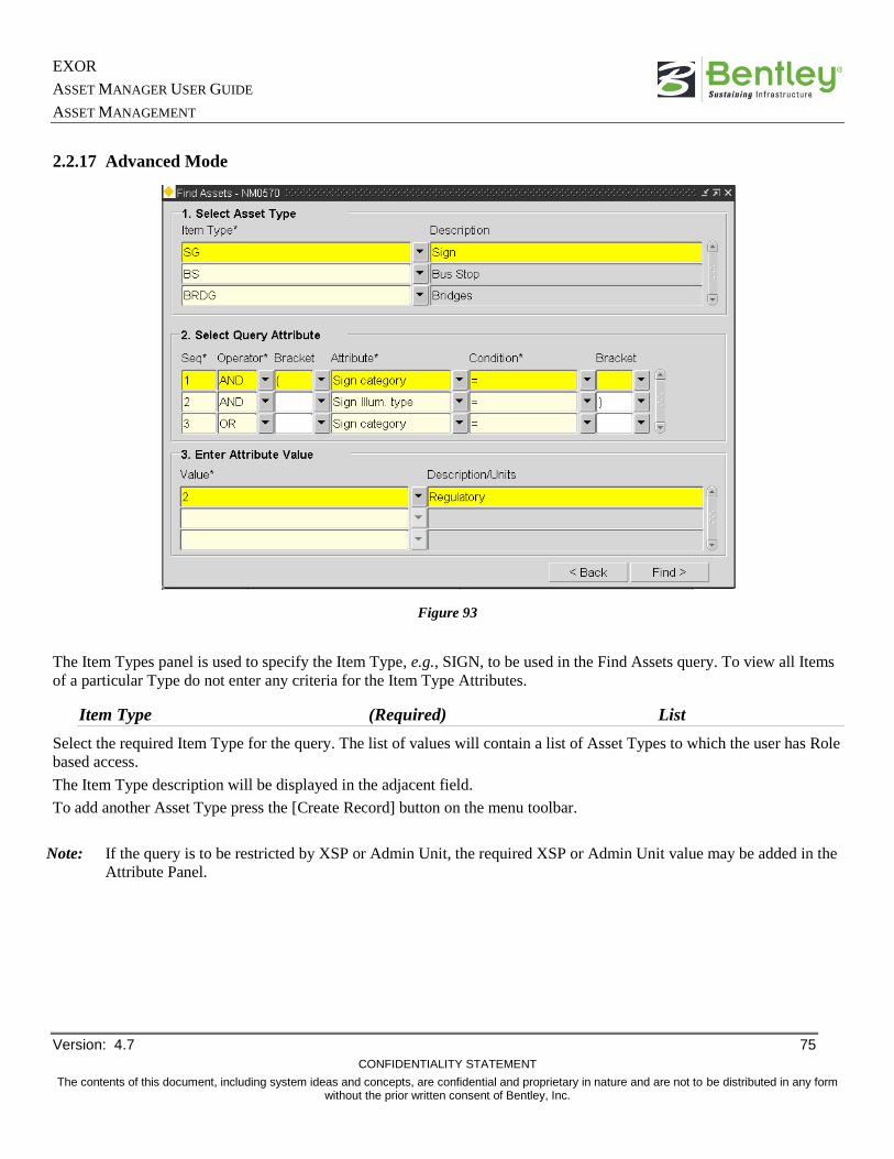
EXOR
ASSET MANAGER USER GUIDE
ASSET MANAGEMENT
Version: 4.7 75
CONFIDENTIALITY STATEMENT
The contents of this document, including system ideas and concepts, are confidential and proprietary in nature and are not to be distributed in any form without the prior written consent of Bentley, Inc.
2.2.17 Advanced Mode
Figure 93
The Item Types panel is used to specify the Item Type, e.g., SIGN, to be used in the Find Assets query. To view all Items
of a particular Type do not enter any criteria for the Item Type Attributes.
Item Type (Required) List
Select the required Item Type for the query. The list of values will contain a list of Asset Types to which the user has Role
based access.
The Item Type description will be displayed in the adjacent field.
To add another Asset Type press the [Create Record] button on the menu toolbar.
Note: If the query is to be restricted by XSP or Admin Unit, the required XSP or Admin Unit value may be added in the
Attribute Panel.

EXOR
ASSET MANAGER USER GUIDE
ASSET MANAGEMENT
Version: 4.7 76
CONFIDENTIALITY STATEMENT
The contents of this document, including system ideas and concepts, are confidential and proprietary in nature and are not to be distributed in any form without the prior written consent of Bentley, Inc.
2.2.18 Attributes Panel
Figure 94
The Attributes panel is used to define the Attributes of the selected Item Type to be used in the filter. If multiple
Attributes are selected the relationship between the Attributes may be defined as an 'AND' or 'OR' relationship. Attribute
criteria may also be nested with 5 levels of nesting available if required by using the Pre and Post brackets as required.
Seq (Required)
Enter the sequence number for the Attribute. Attributes values are resolved in the defined sequence order.
Operator (Required) List
Select the required Boolean connector.
Note: The Operator or the Sequence 1 Attribute must always be 'AND'.
Bracket List
If required select the appropriate Pre Bracket.
Attribute (Required) List
Select the Attribute of the selected Item to be used in the Gazetteer Filter.
Condition (Required) List
Enter the condition for the selected attribute. These are standard Oracle conditions and are set up and maintained using
Domains–HIG9120 and updating the PBI_CONDITION option.
Bracket List
If required select the appropriate Post Bracket.

EXOR
ASSET MANAGER USER GUIDE
ASSET MANAGEMENT
Version: 4.7 77
CONFIDENTIALITY STATEMENT
The contents of this document, including system ideas and concepts, are confidential and proprietary in nature and are not to be distributed in any form without the prior written consent of Bentley, Inc.
2.2.19 Values Panel
Figure 95 - Values
This panel is used to define the parameter values for the currently selected Attribute.
Value (Required) (List)
Enter the required ‘Query’ value for the currently selected Attribute. If the attribute values are held in a Domain, the List
of Values may be called and the description of the selected value will be displayed. If the ‘Condition’ entered for the
Attribute is ‘BETWEEN’ enter the second value in the field below.
If a List of Values is called the extended LOV window will be called as shown in Figure 96.

EXOR
ASSET MANAGER USER GUIDE
ASSET MANAGEMENT
Version: 4.7 78
CONFIDENTIALITY STATEMENT
The contents of this document, including system ideas and concepts, are confidential and proprietary in nature and are not to be distributed in any form without the prior written consent of Bentley, Inc.
Figure 96
This list will display the Domain Lookup Values and Descriptions associated with the selected Attribute.
The Display of the available Values may be ordered by the Lookup Value or by the Description by pressing the [Value]
button or the [Meaning] button respectively.
This will also determine which field (Value or Description) will be used when refining the search criteria to limit the
Values displayed. For example, to search for all lookup values that begin with ‘01’, press the [Value] button then enter
01% in the ‘Find’ field and press the [Find] button on the Values LOV window.
Click on the required Lookup Value to select, and press the [Select Values] button on the Values form. To close the
window without selecting a Value press the [Cancel] button.
To exit the Find Assets window and return to the Asset Item window without executing the query press the [Cancel]
button otherwise press [Next >] to view the list of Assets which met the selection criteria. The available Assets are
displayed in the Matching Items window.

EXOR
ASSET MANAGER USER GUIDE
ASSET MANAGEMENT
Version: 4.7 79
CONFIDENTIALITY STATEMENT
The contents of this document, including system ideas and concepts, are confidential and proprietary in nature and are not to be distributed in any form without the prior written consent of Bentley, Inc.
2.2.20 Matching Items
Figure 97
The Matching Items window displays the details of the Assets that met the selection criteria defined in the Find Assets
window.
The Asset Type and Asset Type description are displayed along with the Item Attributes. These attribute include the User
definable flexible attributes along with the following 'fixed' attributes:
XSP
Admin Unit
Description
Start Date
The Asset location is displayed in the Location Panel as shown in Figure 97.
This window is displayed in READONLY mode therefore attribute values may not be updated. If however an Items
attributes are to be updated, the currently selected Asset or Reference Item may 'expanded' to call the Asset Items–
NM0510 module where the attribute details, location, etc may be amended so long as the User has the required Role based
access to that module, by pressing the [Expand] button on the menu toolbar.

EXOR
ASSET MANAGER USER GUIDE
ASSET MANAGEMENT
Version: 4.7 80
CONFIDENTIALITY STATEMENT
The contents of this document, including system ideas and concepts, are confidential and proprietary in nature and are not to be distributed in any form without the prior written consent of Bentley, Inc.
2.2.21 Location Panel
Figure 98 - Locations
The Route, Datum and Groups Tabs in the Locations panel are used to display the location(s) of an Asset Item on a
Network relative to the Route(s) (linear Groups), member Datum Elements and Groups (non linear) on which it is located.
The Network Type, Group Type, Group Description and Unit of Measurement are displayed for the currently selected
record within the 'Route' tab. The Unit of Measurement displayed will be in accordance with the Unit defined for the
Group Type or Datum Network on which the Item is located.
Figure 99 – Details Button
The Attribute Details of a Route, Datum or Group may be displayed by selecting the required Network record and
clicking the Right mouse button. This will display a [Details] button as shown in Figure 99. Pressing this button will
display the Attributes for the selected Network record as shown in Figure 100. The Attribute values are displayed in Read-
only mode.

EXOR
ASSET MANAGER USER GUIDE
ASSET MANAGEMENT
Version: 4.7 81
CONFIDENTIALITY STATEMENT
The contents of this document, including system ideas and concepts, are confidential and proprietary in nature and are not to be distributed in any form without the prior written consent of Bentley, Inc.
Figure 100 - Attributes
The display of an Items location(s) may be restricted to a specific LRM (linear Referencing Method) by setting the
Preferred LRM to the appropriate Group Type. This is done within the User Preferences form (refer to the General User
Guide). If an Item is not located on a Route of the specified Type, then the Items location will be displayed relative to
ALL LRMS on which it has a location.
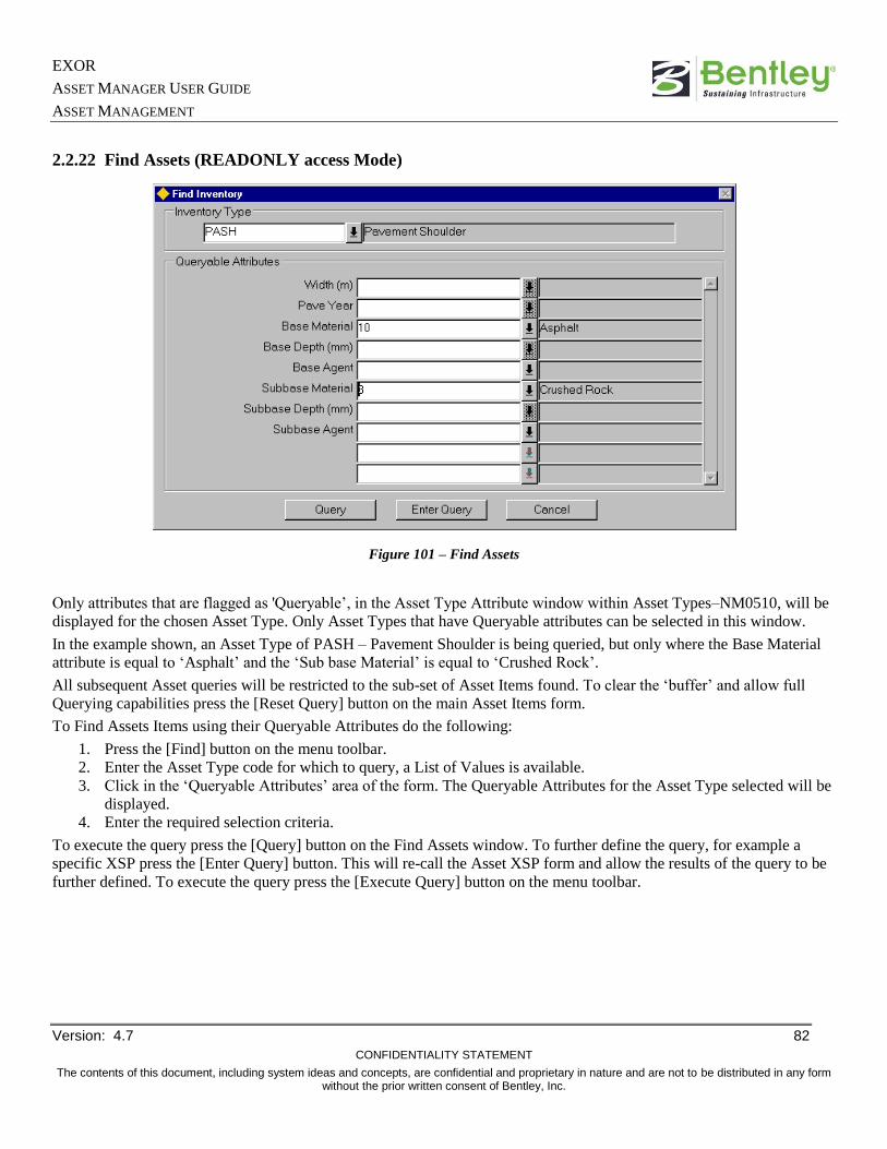
EXOR
ASSET MANAGER USER GUIDE
ASSET MANAGEMENT
Version: 4.7 82
CONFIDENTIALITY STATEMENT
The contents of this document, including system ideas and concepts, are confidential and proprietary in nature and are not to be distributed in any form without the prior written consent of Bentley, Inc.
2.2.22 Find Assets (READONLY access Mode)
Figure 101 – Find Assets
Only attributes that are flagged as 'Queryable’, in the Asset Type Attribute window within Asset Types–NM0510, will be
displayed for the chosen Asset Type. Only Asset Types that have Queryable attributes can be selected in this window.
In the example shown, an Asset Type of PASH – Pavement Shoulder is being queried, but only where the Base Material
attribute is equal to ‘Asphalt’ and the ‘Sub base Material’ is equal to ‘Crushed Rock’.
All subsequent Asset queries will be restricted to the sub-set of Asset Items found. To clear the ‘buffer’ and allow full
Querying capabilities press the [Reset Query] button on the main Asset Items form.
To Find Assets Items using their Queryable Attributes do the following:
1. Press the [Find] button on the menu toolbar.
2. Enter the Asset Type code for which to query, a List of Values is available.
3. Click in the ‘Queryable Attributes’ area of the form. The Queryable Attributes for the Asset Type selected will be
displayed.
4. Enter the required selection criteria.
To execute the query press the [Query] button on the Find Assets window. To further define the query, for example a
specific XSP press the [Enter Query] button. This will re-call the Asset XSP form and allow the results of the query to be
further defined. To execute the query press the [Execute Query] button on the menu toolbar.

EXOR
ASSET MANAGER USER GUIDE
ASSET MANAGEMENT
Version: 4.7 83
CONFIDENTIALITY STATEMENT
The contents of this document, including system ideas and concepts, are confidential and proprietary in nature and are not to be distributed in any form without the prior written consent of Bentley, Inc.
2.2.23 Locations
Figure 102 - Locations
The Route, Datum and Groups Tabs in the ‘Hierarchy and Locations’ window are used to display the location(s) of an
Asset Item on a Network relative to the Route(s) (linear Groups), Route Mile Post, Datum Elements and Groups (non
linear) on which the Item is located. The Group Type and description and Unit of Measurement are displayed for the
currently selected record in the 'Route' tab. The Unit of Measurement displayed will be in accordance with the Unit
defined for the Group Type or Datum Network on which the Item is located.
Figure 103 - Details
The Attribute Details of a Route, Datum or Group may be displayed by selecting the required Network record and
clicking the Right mouse button. This will display a [Details] button as shown in Figure 103. Pressing this button will
display the Attributes for the selected Network record as shown in Figure 104. The Attribute values are displayed in Read-
only mode.

EXOR
ASSET MANAGER USER GUIDE
ASSET MANAGEMENT
Version: 4.7 84
CONFIDENTIALITY STATEMENT
The contents of this document, including system ideas and concepts, are confidential and proprietary in nature and are not to be distributed in any form without the prior written consent of Bentley, Inc.
Figure 104 - Attributes
The display of an Items location(s) may be restricted to a specific LRM (linear Referencing Method) by setting the
Preferred LRM to the appropriate Group Type. This is done within the User Preferences form (refer to the General User
Guide). If an Item is not located on a Route of the specified Type, then the Items location will be displayed relative to
ALL LRMS on which it has a location.
Note: If Product Option 'INVRTETAB' is set to 'Y' the Route Tab will be the default display tab, otherwise the Datum
Tab will be defaulted.
A ‘Continuous’ Asset Item may be located within the extent of a single Network Element, span many contiguous or non
contiguous Elements on a Route or span multiple Routes. If the Item spans multiple Routes or non contiguous Elements
the Item locations may be added separately for each extent of Network on which the Item is located or alternatively may
be located through the use of a Saved Network Extent. When an Asset Item is located the system will check if the Item
already has a Network location. If this is the case the User will be prompted to either ‘Append’ the new location to the
existing or replace the existing location with the newly defined location.
Figure 105 – Existing Location
Note: The Asset Item Type must have the ‘Multiple Allowed’ flag selected in the Asset Metamodel – NM0410 module
in order to have more than one location record.
Asset Items may be located on a Network, relative to any Linear Group that contains the appropriate base Datum Network
Elements. This could include an Inspection Route, State Highway, Abnormal Load Movement Route, etc. When an Asset
Item is located, its position will be displayed relative to each Route (Group) of which the ‘underlying’ Base Datum
Network Element(s) on which the Item is located is a member. This will also include any Groups that do not contain all of
the base Datum Network Elements on which the Item is located.

EXOR
ASSET MANAGER USER GUIDE
ASSET MANAGEMENT
Version: 4.7 85
CONFIDENTIALITY STATEMENT
The contents of this document, including system ideas and concepts, are confidential and proprietary in nature and are not to be distributed in any form without the prior written consent of Bentley, Inc.
Consider the example below.
A continuous Asset Item has been located over the entire extent of 3 Datum Network Elements. The resulting locations
relative to the appropriate Routes or Groups are displayed (note that only Elements 2 & 3 are members of Inspection
Route 2).
Figure 106
An Asset Item may only be located on a Network Type that have been associated with the Asset Item Type in the
‘Networks’ window within the Asset Metamodel form.
If the Asset Type has an associated XSP value, it cannot be located on an extent of Network for which the appropriate
Network Type, Subclass and XSP combination has not been defined for the Asset Item Type.
The following information is displayed for each Asset Item located on a Network in the Datum Tab.
Unique Element Reference on which the Item is Located or partially located.
Start and End Offset relative to the Element
If the Asset Item is ‘split’ and contains a break, or the Datum Network Element(s) belong to multiple Linear Groups, the
Route Tab will display the Start and End Offsets, relative to the Route, of each ‘chunk’ of the Asset Item.

EXOR
ASSET MANAGER USER GUIDE
ASSET MANAGEMENT
Version: 4.7 86
CONFIDENTIALITY STATEMENT
The contents of this document, including system ideas and concepts, are confidential and proprietary in nature and are not to be distributed in any form without the prior written consent of Bentley, Inc.
2.2.24 Viewing an Asset Location using Reference Post Referencing
Figure 107
If Reference Post referencing has been deployed, the location of the selected Asset relative to the nearest preceding
Reference Post will be displayed. If no preceding Reference Post exists the distance to the next Reference Post on the
Route will be displayed. This will be represented as a negative value.
The Reference Post Asset Type used to display the Reference Post Offsets is defined by entering the required Asset Type
for Product or User Option DEFITEMTYP. If a value has been entered in the User Option this will take precedence over
the Product Option value. Refer the General System Admin Guide for further details on Product and User Options.
Start/End Reference Item
The Start and End locations of the currently selected Asset will be displayed relative to the nearest preceding Reference
Post Asset. For point Asset Types the start and end Reference values will be the same.
The following details are displayed:
Reference Post Asset Type
Asset Description (IIT_DESCR)
Distance from preceding Ref Post (or –ve distance to next if no preceding)
Figure 108

EXOR
ASSET MANAGER USER GUIDE
ASSET MANAGEMENT
Version: 4.7 87
CONFIDENTIALITY STATEMENT
The contents of this document, including system ideas and concepts, are confidential and proprietary in nature and are not to be distributed in any form without the prior written consent of Bentley, Inc.
2.2.25 Locate Asset
Figure 109 - Locate Asset (Continuous Item)
Figure 110 - Locate Asset (Point Item)
Asset Items are pl aced on a Network by a method known as Homogeneous Update. This allows ‘continuous’ Items of
Asset to be located within the extent of a single Network Element, span many contiguous or non-contiguous Elements on
a Route or span multiple Routes. If the Item spans multiple Routes or Groups or non-contiguous Elements the Item
locations must be added separately for each extent of Network on which the Item is located.
When an Asset Item is located the system will check if the Item already has a Network location. If this is the case the User
will be prompted to either ‘Append’ the new location to the existing or replace the existing location with the newly
defined location.

EXOR
ASSET MANAGER USER GUIDE
ASSET MANAGEMENT
Version: 4.7 88
CONFIDENTIALITY STATEMENT
The contents of this document, including system ideas and concepts, are confidential and proprietary in nature and are not to be distributed in any form without the prior written consent of Bentley, Inc.
Figure 111
Note: That the Asset Item Type must have the ‘Multiple Allowed’ flag selected in the Asset Metamodel – NM0410
module in order to have more than one location record.
Alternatively a saved Network Extent may be used to locate the ‘continuous’ Asset item.
To locate an Item of Asset on a Network press the [L] Locate Asset button on the floating toolbar.
Note: If the toolbar is not currently displayed press the [Toolbar] button on the menu toolbar.
This will display the Locate Asset dialogue box( Figure 109 and Figure 110). This dialogue box allows the User to select
the Required Network Type or Group Type on which to locate the Asset Item. This is done by pressing the ‘Drop Down
List’ icon adjacent to the ‘Network’ field.
This will call the Gazetteer from where the required Network Type or Group can be selected.
Any ambiguous Linear References supplied may be automatically resolved by specifying the Network Type Subclass on
which to locate the item of Asset. If the Network Type Subclass is unspecified and an ambiguous reference is supplied a
List of Values will be supplied from which the User must select the required Network Element.
2.2.26 Locate a Continuous Item
When the required Network Type, Group or Extent has been selected, the Extent Limits within the selected Group or
Network Type may be defined by pressing the ‘Drop Down List’ icon adjacent to the Location field. This will call the
Extent Limits window (Figure 112).

EXOR
ASSET MANAGER USER GUIDE
ASSET MANAGEMENT
Version: 4.7 89
CONFIDENTIALITY STATEMENT
The contents of this document, including system ideas and concepts, are confidential and proprietary in nature and are not to be distributed in any form without the prior written consent of Bentley, Inc.
Figure 112 - Extent Limits
2.2.27 Extent Limits
The Extent Limits window allows the Start and End points of a selected Route to be defined by Route Offset, Intersection
or Section Offset. For example, to select a Route extent comprising of the first Kilometer of the Route, the Start Point
would be defined as having a Route Offset of ‘0’ and the End Point defined as having a Route Offset of ‘1’.
The tables below show 3 scenarios for Extent Limits, to demonstrate the possibilities.
2.2.28 Scenario 1
Parameters Start Point End Point Result
Route Offset 1 3.5 Elements or partial Elements contained between Route Offset 1 and 3.5 Kilometers
Intersection
Section Offset
2.2.29 Scenario 2
Parameters Start Point End Point Result
Route Offset 0.24 Elements or partial Elements contained between the Intersection at Node 82730 and Route Offset 0.24
Intersection 082730
Section Offset

EXOR
ASSET MANAGER USER GUIDE
ASSET MANAGEMENT
Version: 4.7 90
CONFIDENTIALITY STATEMENT
The contents of this document, including system ideas and concepts, are confidential and proprietary in nature and are not to be distributed in any form without the prior written consent of Bentley, Inc.
2.2.30 Scenario 3
Parameters Start Point End Point Result
Route Offset 5.6 Elements or partial Element contained between 35m along Element H004/1-S and Route Offset 5.6 Kilometers
Intersection
Section Offset H004/1-S
35
2.2.31 Sub Class
Figure 113 - Subclass
The ‘Sub Class’ panel allows the User to choose the Sub Class of the Elements, within the defined extent limits, on which
to locate the Asset Item. If neither the Sub Class ‘When Ambiguous’ or ‘Restrict to Exclusive’ field are populated, the
Asset Item will be located on Elements of all Sub-Classes within the defined extent limits.
2.2.32 Restrict to Exclusive
An Asset Items location may be restricted to a single ‘Exclusive’ Sub Class by selecting the ‘Restrict to Exclusive’ check
box and entering the required Sub-Class in the adjacent field. This will restrict the Asset Locations to Elements whose
Sub Class match the selected Sub Class.
Consider the following example:
Figure 114
The Route displayed in Figure 114 contains a combination of Network Type Subclasses. An item of Asset is to be located
within the extent limits shown, but only where the Network Type Sub Class is ‘L’ – Left.

EXOR
ASSET MANAGER USER GUIDE
ASSET MANAGEMENT
Version: 4.7 91
CONFIDENTIALITY STATEMENT
The contents of this document, including system ideas and concepts, are confidential and proprietary in nature and are not to be distributed in any form without the prior written consent of Bentley, Inc.
By selecting the ‘Restrict to Exclusive’ checkbox and entering a value of ‘L’ – left in the adjacent field, the Asset Item
will only be located on Elements (or parts of) with a Network Type Subclass of ‘L’ – Left. Therefore the Asset Location
would include the following Elements:- 3-L,4-L, 8-L, 9-L
2.2.33 Ambiguous References
Any Ambiguous references within the selected extent limits may be automatically resolved by entering the required
Network Type Sub-class in the ‘Subclass’ field.
Consider the following example
Figure 115
The Route displayed in Figure 115 contains a combination of Network Type Subclasses. An item of Asset is to be located
within the extent limits shown, but only where the Network Type Sub Class is either ‘S’ – Single or ‘L’ – Left.
By entering a value of ‘L’ – left in the Sub Class ‘When Ambiguous’ field of the extent limits window, the Asset Item
will only be located on Elements (or parts of) with a Network Type Subclass of ‘S’ – Single and those Elements (or parts
of) with a Network Type Sub Class of ‘L’ –Left. Therefore the Asset Location would include the following Elements:–1-
S, 2-S, 3-L, 4-L, 5-S, 8-L, 9-L, 12-S

EXOR
ASSET MANAGER USER GUIDE
ASSET MANAGEMENT
Version: 4.7 92
CONFIDENTIALITY STATEMENT
The contents of this document, including system ideas and concepts, are confidential and proprietary in nature and are not to be distributed in any form without the prior written consent of Bentley, Inc.
Route (Display Only)
The Unique Route reference description and Route Length will be displayed.
Sub Class When Ambiguous (Optional)
Enter the required Network Element Sub Class for Elements that should be selected if any ambiguity arises.
Sub Class –Restrict to Exclusive (Optional)
Enter the required Network Element Sub Class to which the selection should be restricted.

EXOR
ASSET MANAGER USER GUIDE
ASSET MANAGEMENT
Version: 4.7 93
CONFIDENTIALITY STATEMENT
The contents of this document, including system ideas and concepts, are confidential and proprietary in nature and are not to be distributed in any form without the prior written consent of Bentley, Inc.
2.2.34 Start Point
Select one of the following Radio button to define the Start Point along the selected Route. The default selection is by
Route Offset.
Route Offset (Default)
Enter the Route Offset for the Start Point. This should be entered in the unit of measurement defined for the selected
Group or Network Type. The defined Unit will be displayed adjacent to the Route Offset measure. The Route Offset will
be defaulted to ‘0’.
Intersection (List)
Enter the Node point of the Intersection for the Start Point. The list of values will display all the Intersection Node details
for the selected Route.
Figure 116 - Nodes
The Display of the available Nodes may be ordered by the Node Name or by the Node Description by pressing the
[Value] button or the [Meaning] button respectively.
This will also determine which field (Node Name or Description) will be used when refining the search criteria to limit
the Nodes displayed. For example, to search for all Node points of the Selected Node type that begin with ‘01’, press the
[Value] button then enter 01% in the ‘Find’ field and press the [Find] button on the Nodes window.
Click on the required Node Point to select, and press the [Select Values] button on the Nodes form. To close the window
without selecting a Node, press the [Cancel] button.
Section Offset (List)
Enter the Unique Element reference for the Start Point. The Element description will be displayed in the adjacent field.
The list of values will display all the Network Element within the selected Route.
Enter the Element Offset in the unit of measurement defined for the Datum Element in Network Types–NM0002. The
measured length of the Element will be displayed in the adjacent field.

EXOR
ASSET MANAGER USER GUIDE
ASSET MANAGEMENT
Version: 4.7 94
CONFIDENTIALITY STATEMENT
The contents of this document, including system ideas and concepts, are confidential and proprietary in nature and are not to be distributed in any form without the prior written consent of Bentley, Inc.
2.2.35 End Point
Select one of the following Radio button to define the Start Point along the selected Route. The default selection is by
Route Offset
Route Offset (Default)
Enter the Route Offset for the End Point. This should be entered in the unit of measurement defined for the selected
Group or Network Type. The defined Unit will be displayed adjacent to the Route Offset measure. The Route Offset of
the End of the Route will be displayed as the default value.
Intersection (List)
Enter the Node point of the Intersection for the End Point. The list of values will display all the Intersection Node details
for the selected Route.
Section Offset (List)
Enter the Unique Element reference for the End Point. The Element description will be displayed in the adjacent field.
The list of values will display all the Network Element within the selected Route.
Enter the Element Offset in the unit of measurement defined for the Datum Element in Network Types–NM0002. The
measured length of the Element will be displayed in the adjacent field.
The ‘Locate Asset’ window will be displayed and the Extent Limits selected will be displayed as Offset values relative to
the selected Network Type or Group.
Effective Date (Required, Default)
Enter the effective date of the Asset Item Location. This may be a different date than the effective date of the Asset Item,
but may not precede the Asset Item Date.
To Locate the Asset Item press the [Locate] button.
When an Asset Item is located the system will check if the Item already has a Network location. If this is the case the User
will be prompted to either ‘Append’ the new location to the existing or replace the existing location with the newly
defined location.
Figure 117
Note: The Asset Item Type must have the ‘Multiple Allowed’ flag selected in the Asset Metamodel – NM0410 module
in order to have more than one location record.
Press the [Save] button on the menu toolbar to save the Asset Locations.

EXOR
ASSET MANAGER USER GUIDE
ASSET MANAGEMENT
Version: 4.7 95
CONFIDENTIALITY STATEMENT
The contents of this document, including system ideas and concepts, are confidential and proprietary in nature and are not to be distributed in any form without the prior written consent of Bentley, Inc.
2.2.36 Locate a Point Item
To add a Location for a Point Item of Asset use the Gazetteer to ‘Drill Down’ to the Network Element level in the
hierarchy and select the required Element or select the Route on which the Asset Item is located.
The Locate Asset window will be called allowing the User to specify the position of the Asset Item on the selected
Network Element. If a Route has been selected enter the Route Offset or if a Datum Element has been selected enter the
Offset relative to the start of the Element . The Unit of Measurement used will be determined by the Unit defined for the
Network Type associated with the Route Group or Datum Element.
To locate a point Item at an Intersection along a Route, press the [Edit Location] button. This will call the extent limits
window. Press the ‘Drop Down List’ icon adjacent to the ‘Intersection’ field. Enter the Node point of the Intersection for
the Start Point. The list of values will display all the Intersection Node details for the selected Route.
Figure 118 - Nodes
The Display of the available Nodes may be ordered by the Node Name or by the Node Description by pressing the
[Value] button or the [Meaning] button respectively.
This will also determine which field (Node Name or Description) will be used when refining the search criteria to limit
the Nodes displayed. For example, to search for all Node points of the Selected Node type that begin with ‘01’, press the
[Value] button then enter 01% in the ‘Find’ field and press the [Find] button on the Nodes window.
Click on the required Node Point to select, and press the [Select Values] button on the Nodes form. To close the window
without selecting a Node press the [Cancel] button.

EXOR
ASSET MANAGER USER GUIDE
ASSET MANAGEMENT
Version: 4.7 96
CONFIDENTIALITY STATEMENT
The contents of this document, including system ideas and concepts, are confidential and proprietary in nature and are not to be distributed in any form without the prior written consent of Bentley, Inc.
Effective Date (Required, Default)
Enter the effective date of the Asset Item Location. This may be a different date than the effective date of the Asset Item,
but may not precede the Asset Item Date.
To Locate the Asset Item press the [Locate] button.
When an Asset Item is located the system will check if the Item already has a Network location. If this is the case the User
will be prompted to either ‘Append’ the new location to the existing or replace the existing location with the newly
defined location.
Figure 119
Note: The Asset Item Type must have the ‘Multiple Allowed’ flag selected in the Asset Metamodel – NM0410 module
in order to have more than one location record.
Press the [Save] button on the menu toolbar to save the Asset Locations.

EXOR
ASSET MANAGER USER GUIDE
ASSET MANAGEMENT
Version: 4.7 97
CONFIDENTIALITY STATEMENT
The contents of this document, including system ideas and concepts, are confidential and proprietary in nature and are not to be distributed in any form without the prior written consent of Bentley, Inc.
2.2.37 Locate Asset using a Saved Network Extent
Figure 120 - Locate Asset by Saved Extent
Continuous Asset Items may be located on a network using a Saved Network Extent. This will place the Item on all
‘chunks’ of network within the saved extent.
The Network Extent used to locate an Item of Continuous Asset may include Elements which a wholly or partially
contained within the extent.
When using a Network Extent to locate Asset, Product Option MULTINVRTE must be set to suit your Organisational
Requirements. If this option is set to ‘Y’ the Network Extent may contain Elements from multiple Routes or Groups. If
the Option is set to ‘N’ the Network Extent must contain Elements from within a single Group. If MULTINVRTE is set to
‘N’ and an inappropriate Network Extent is used the message in to be displayed.
Figure 121
These need not be connected but ALL the member Elements must be wholly within a Single Network Group, e.g., a
Single Route.

EXOR
ASSET MANAGER USER GUIDE
ASSET MANAGEMENT
Version: 4.7 98
CONFIDENTIALITY STATEMENT
The contents of this document, including system ideas and concepts, are confidential and proprietary in nature and are not to be distributed in any form without the prior written consent of Bentley, Inc.
If the selected Network Extent contains Overlaps (i.e., the same extent of network is included more than once within the
Network Extent) the message below will be displayed, preventing the Network Extent be used.
Figure 122 - Overlap
Effective Date (Required, Default)
Enter the effective date of the Asset Item Location. This may be a different date than the effective date of the Asset Item,
but may not precede the Asset Item Date.
To Locate the Asset Item press the [Locate] button.
When an Asset Item is located the system will check if the Item already has a Network location. If this is the case the User
will be prompted to either ‘Append’ the new location to the existing or replace the existing location with the newly
defined location.
Figure 123
Note: The Asset Item Type must have the ‘Multiple Allowed’ flag selected in the Asset Metamodel – NM0410 module
in order to have more than one location record.
Press the [Save] button on the menu toolbar to save the Asset Locations.

EXOR
ASSET MANAGER USER GUIDE
ASSET MANAGEMENT
Version: 4.7 99
CONFIDENTIALITY STATEMENT
The contents of this document, including system ideas and concepts, are confidential and proprietary in nature and are not to be distributed in any form without the prior written consent of Bentley, Inc.
2.2.38 Locate an Asset using Reference Post Referencing
Assets may be located relative to the absolute distance from a known reference marker, such as a Route Milepost, using
the ‘Reference Post’ tab of the Locate Asset window (Figure 124). This is called by pressing the [Locate Asset] button on
the floating toolbar.
Figure 124
Reference Post or ‘Route Mile Post’ referencing, allows the location of an Asset to be expressed relative to the distance
from a known ‘reference’ Asset, located on the selected Route. The ‘Reference’ Asset must be a ‘Point Item’ and can be
either an Asset stored within the Exor database or an External Asset.
The ‘Reference Post Offset’ is always entered relative to the Route cardinality. Therefore a positive distance from a
Reference Post means that the Asset is located further along the Route than the ‘reference Post’, where as a negative
distance means the Asset is located on the Route before the ‘reference post’.
If no reference Item is specified, the Reference Offset is taken as the distance from the Start of the Route.
Consider the following example:
Figure 125

EXOR
ASSET MANAGER USER GUIDE
ASSET MANAGEMENT
Version: 4.7 100
CONFIDENTIALITY STATEMENT
The contents of this document, including system ideas and concepts, are confidential and proprietary in nature and are not to be distributed in any form without the prior written consent of Bentley, Inc.
Asset ‘A’ could be located in several different ways relative to the Marker Posts (MP) shown in the diagram. Its start
location could be expressed as follows.
Route
1
MP
1
Offset
0.75
Or
Route
1
MP
2
Offset
-0.25
Or
Route
1
MP
null
Offset
1.75
Its end location could be expressed as follows:
Route
1
MP
3
Offset
0.1
Or
Route
1
MP
4
Offset
-0.85
Or
Route
1
MP
null
Offset
3.1

EXOR
ASSET MANAGER USER GUIDE
ASSET MANAGEMENT
Version: 4.7 101
CONFIDENTIALITY STATEMENT
The contents of this document, including system ideas and concepts, are confidential and proprietary in nature and are not to be distributed in any form without the prior written consent of Bentley, Inc.
2.2.39 Route Panel
Figure 126
Route Required List, Gaz
Enter the Route on which the Asset is to be located. The Route description will be displayed in the adjacent field.
Start/End
The Min and Max Offsets for Route will be displayed. Only Reference Post Assets, of the selected Type, that are located
between the specified Start and End Offsets will be available for selection when the Start/End Ref post Offsets are
entered. This allows the LOV of Reference Post items to be restricted on long Routes.
2.2.40 Start/End Reference
Figure 127
The Start and End Reference panels are used to specify the start and end locations of an Asset relative to a Reference Post
Item
Note: The End Reference panel is disabled when locating a ‘Point’ Asset.
Type Default List
This is ‘referencing Asset Type’. Any Point Asset Type of categories ‘I’ – General Assets, ‘F’ – External Assets or ‘D’ –
Derived Assets, to which the User has access and which can be located on the selected Route Type, may be chosen. A
default Reference Type can be defined by setting User/product Option DEFITEMTYP to the required Point Asset Type.
Refer to the General User Guide for information on how to define User Options.
Item List
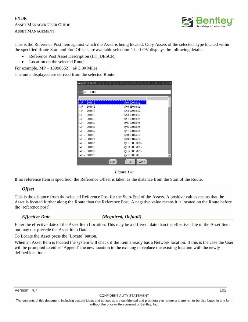
EXOR
ASSET MANAGER USER GUIDE
ASSET MANAGEMENT
Version: 4.7 102
CONFIDENTIALITY STATEMENT
The contents of this document, including system ideas and concepts, are confidential and proprietary in nature and are not to be distributed in any form without the prior written consent of Bentley, Inc.
This is the Reference Post item against which the Asset is being located. Only Assets of the selected Type located within
the specified Route Start and End Offsets are available selection. The LOV displays the following details:
Reference Post Asset Description (IIT_DESCR)
Location on the selected Route
For example, MP – 13098652 @ 3.00 Miles
The units displayed are derived from the selected Route.
Figure 128
If no reference Item is specified, the Reference Offset is taken as the distance from the Start of the Route.
Offset
This is the distance from the selected Reference Post for the Start/End of the Assets. A positive values means that the
Asset is located further along the Route than the Reference Post. A negative value means it is located on the Route before
the ‘reference post’.
Effective Date (Required, Default)
Enter the effective date of the Asset Item Location. This may be a different date than the effective date of the Asset Item,
but may not precede the Asset Item Date.
To Locate the Asset press the [Locate] button.
When an Asset Item is located the system will check if the Item already has a Network location. If this is the case the User
will be prompted to either ‘Append’ the new location to the existing or replace the existing location with the newly
defined location.

EXOR
ASSET MANAGER USER GUIDE
ASSET MANAGEMENT
Version: 4.7 103
CONFIDENTIALITY STATEMENT
The contents of this document, including system ideas and concepts, are confidential and proprietary in nature and are not to be distributed in any form without the prior written consent of Bentley, Inc.
Figure 129
Note: The Asset Item Type must have the ‘Multiple Allowed’ flag selected in the Asset Metamodel – NM0410 module
in order to have more than one location record.

EXOR
ASSET MANAGER USER GUIDE
ASSET MANAGEMENT
Version: 4.7 104
CONFIDENTIALITY STATEMENT
The contents of this document, including system ideas and concepts, are confidential and proprietary in nature and are not to be distributed in any form without the prior written consent of Bentley, Inc.
2.2.41 Hierarchy
Figure 130 - Asset Hierarchy
The Hierarchy Tab in the ‘Hierarchy and Locations’ panel is used to display a graphical representation of an Asset
Grouping. It is also used to add new ‘Child’ Items to a Grouping or hierarchy or to add new Asset Items of any type to the
database. The ‘primary key’ of each item within the hierarchy is displayed adjacent to the Item Type.
When adding Items in a Hierarchy the ‘Top Level’ item should be added first in the normal manner. Once saved this Item
will be displayed in the ‘Hierarchy’ window if an Icon has been associated with the Asset Type in the Asset Metamodel –
NM0410 form it will be displayed adjacent to the Asset Type Name and Unique Reference.
To add a ‘Child’ item to the grouping, select the ‘Childs’ parent Item in the Hierarchy window and press the [Create Child
Item] button on the Hierarchy Tab.
This will create a new sub item in the grouping with a temporary name of ‘New Item’.
The cursor will return to the ‘Type’ field in the main Asset Items form awaiting the selection and entry of the New Item
details. The List of allowable Asset types will be restricted to those Item Types which have the selected ‘Parent’ Item
Type defined in the ‘Groupings’ Tab of the Asset Metamodel form as the ‘Parent Type’. Enter the remaining Asset Item
details as required to complete the Asset Grouping.
To add further Items to the grouping, select the Parent Item in the Hierarchy Diagram and repeat the process.
When a hierarchical Inventory Item is queried back, the entire Asset Grouping of which the Item is a member will be
displayed in the hierarchy browser. To view the details of an Item in the grouping, Double Click on the required Item.
This will recursively call the Asset Item form and display the details of the selected Item. To return to the originally
queried Item press the [Previous Item] button on the Asset Item form.

EXOR
ASSET MANAGER USER GUIDE
ASSET MANAGEMENT
Version: 4.7 105
CONFIDENTIALITY STATEMENT
The contents of this document, including system ideas and concepts, are confidential and proprietary in nature and are not to be distributed in any form without the prior written consent of Bentley, Inc.
2.2.42 Groupings
Figure 131 - Groupings
The Asset Groupings window is only available for ‘Child Items’ within an Asset Grouping as if for Display purposes
only, i.e., no Updates may be made in the window.
It displays the following information for the selected ‘Child’ item within an Asset Grouping.
Top Item in Grouping
Immediate Parent Item (this may be the same as the Top Item)
The selected Item Name (and internal Unique NE_ID)
Start and End Dates of the Selected Item.

EXOR
ASSET MANAGER USER GUIDE
ASSET MANAGEMENT
Version: 4.7 106
CONFIDENTIALITY STATEMENT
The contents of this document, including system ideas and concepts, are confidential and proprietary in nature and are not to be distributed in any form without the prior written consent of Bentley, Inc.
2.2.43 Asset Location History
\
Figure 132 - Location History
Over a period of time Asset locations may amended, for example when a Network Split or Network Merge operation is
carried out on a section of Network on which an Item of Asset is located or when a resurvey is conducted and the
exclusivity rules force the ‘End Dating’ of a portion of the Asset extent.
The entire locational history for each Asset Item may be view by pressing the [H] – Location History button on the
floating toolbar. As well as the Asset Location (relative to the Datum Network) of an Asset Item, the Operation, e.g., Split
or Merge that resulted in a change in the Asset Location will be displayed. The display order of the Asset location history
may be determined by pressing the ‘Drop Down List’ icon adjacent to the ‘Order By’ field and selecting either ‘End Date’
or ‘True Distance’.

EXOR
ASSET MANAGER USER GUIDE
ASSET MANAGEMENT
Version: 4.7 107
CONFIDENTIALITY STATEMENT
The contents of this document, including system ideas and concepts, are confidential and proprietary in nature and are not to be distributed in any form without the prior written consent of Bentley, Inc.
2.2.44 Copy Asset
Figure 133 - Copy Asset
Asset Items and their associated Attribute details may be copied and subsequently located on a Network using the [C] –
Copy Current Item button on the floating toolbar.
The Attribute values of the resultant Asset Item may be edited as required.
Note: The Asset Item location(s) are not copied.
To Copy an Asset Item, do the following.
1. Query back the required Asset Item
2. Ensure that the required Asset Item is selected.
3. Press the [Copy] – Copy Current Item button on the menu toolbar.
This will call the ‘Copy Asset’ dialogue (Figure 134)
4. Enter the Start Date for the new Item.
5. Press the [Create] button on the window.
The Asset form will be called recursively and the new Item displayed.
6. To save the new Item, press the [Save] button on the menu toolbar.
The Asset Item may be located in the normal manner using the [L] – Locate Asset button on the floating toolbar.
If the Asset Item being copied has an Attribute that uses the column IIT_PRIMARY_KEY, the window will include the
Attribute to allow the User to enter a value. An example is shown in Figure 134.
Figure 134

EXOR
ASSET MANAGER USER GUIDE
ASSET MANAGEMENT
Version: 4.7 108
CONFIDENTIALITY STATEMENT
The contents of this document, including system ideas and concepts, are confidential and proprietary in nature and are not to be distributed in any form without the prior written consent of Bentley, Inc.
2.2.45 End Location
Figure 135 - End Date Location
Asset Item Locations may be end-dated (leaving the Asset Item ‘open’) by pressing the [End Location] button on the
Asset Items Floating Toolbar. This will also End Date the locations of any ‘child’ items that exist within an Asset
Hierarchy of which the selected Item is a member. The date at which to End the Location should be entered in the
‘Effective Date’ field.
Asset Items of a Type flagged as having a Mandatory Location in the ‘Networks’ panel of the Asset Metamodel –
NM0410 module cannot have their locations End Dated. If this operation is attempted, the message shown in Figure 136
will be displayed.
Figure 136
If the Asset Type of the Asset Item that has had its location End-Dated has been flagged as ‘Contiguous’ i.e., may have no
overlaps or gaps within the extent of an element, in the Asset Metamodel – NM0410 module, the message shown in
Figure 137 will be displayed to warn the User.
Figure 137
To save the End Dating of an Asset Item Location press the [Save] button on the menu Toolbar.
Note: The Full Location History of an item of Asset may be viewed by pressing the [Location History] button on the
Floating Toolbar.

EXOR
ASSET MANAGER USER GUIDE
ASSET MANAGEMENT
Version: 4.7 109
CONFIDENTIALITY STATEMENT
The contents of this document, including system ideas and concepts, are confidential and proprietary in nature and are not to be distributed in any form without the prior written consent of Bentley, Inc.
2.2.46 Navigator
If an asset has data linked to it from other functions within the system, for example child assets, defects, enquiries or has
been linked to a scheme or a cyclic schedule the navigator form will be displayed showing the relevant associations for
the selected asset in the form of a hierarchy. This may be viewed using the Navigator button on the floating toolbar. The
‘floating toolbar’ is toggled on and off by pressing the [Toolbar] button on the menu toolbar.
An example of an assets hierarchy is shown below:
Figure 138
Navigator displays a summary of the associated records, double clicking on any of the records in the tree will display the
full details of the record in the appropriate form.
Full details of the use of navigator can be found in the Navigator and Query Builder User Guide.

EXOR
ASSET MANAGER USER GUIDE
ASSET MANAGEMENT
Version: 4.7 110
CONFIDENTIALITY STATEMENT
The contents of this document, including system ideas and concepts, are confidential and proprietary in nature and are not to be distributed in any form without the prior written consent of Bentley, Inc.
2.3 Assets on a Route – NM0560
Figure 139 - Assets on a Route Menu Option
The Assets On Route–NM0560 module is used to display Asset Items located on the selected Route, ordered by Route
Offset, with a Reference Offset measure value being calculated for each Asset Item relative to the selected Reference
Event. The Reference Event may be selected from one of the following:
the start of the Route
a selected Offset along the Route
the nearest preceding Asset Item of a specified Type (or nearest Item of the Type if none are preceding)
a specific Asset Item
When selecting either an Item Type or specific Asset Item as the Reference Event, Asset data held in 'Foreign Tables' may
also be chosen. For further information on Foreign Table data refer to the Asset Manager System Admin Guide.
The Asset Items to be displayed on the Assets on Route Results window may be selected using a PBI (Parameter Based
Inquiry) query. This allows for both simple queries such as, display all Items of type SIGN and BRID, or more complex
queries such as, display Items of type SIGN where the TYPE attribute is equal to 'STOP' and the CONDITION RATING
attribute is less than 3.
When selecting the Displayable Items the User may select an existing PBI Query (see page 190 for information on
defining a PBI Query), create a new PBI style filter or use a Default PBI query if one has been defined for the User. As
with the Reference Events data held in 'Foreign Tables' may be chosen for display in the Assets on Route Results window.
The selected Asset Items may be displayed both in a Graphical 'Strip Map' and in tabular format to allow the visual
display of their relative position. The Strip Map is a 'floating window' and may be switched on by pressing the [Show
Strip Map] button on the Assets on a Route Results window. If System Option AORSTRMAP is set to 'Y' the Strip Map
will automatically be displayed when the Results page is displayed. This System Option is both a Product Option and a
User Option. If a User Option value is set this will take precedence over the Product Option.
The Strip Map does not display Asset Items relative to any XSP, instead each Item Type within an XSP is displayed on a
separate row. For example, if SIGNS where being displayed and there are 2 valid XSP's (Left and Right) for SIGN Items
along the selected Route, 2 separate rows of graphical Items would be displayed, i.e., SIGN (Right) and SIGN (Left). This
ensures that Asset Items of different Types that are located at the same Offset and XSP are not obscured.
The Asset attributes for the selected Item are displayed in the Item Attributes panel at the bottom left of the Results
window. The Asset Item Attributes may also be displayed in a 'matrix' format by pressing the 'Attribute' tab in the middle
Assets panel (Figure 140).

EXOR
ASSET MANAGER USER GUIDE
ASSET MANAGEMENT
Version: 4.7 111
CONFIDENTIALITY STATEMENT
The contents of this document, including system ideas and concepts, are confidential and proprietary in nature and are not to be distributed in any form without the prior written consent of Bentley, Inc.
The Attributes displayed for an Asset Type may be restricted by selecting an appropriate Asset Attribute Set. This will
restrict the Attributes displayed on the Assets on a Route Results window (and any subsequent reports called from the
AOR Results window) to those Attributes associated with the Attribute Set. Attribute Sets are created using the Asset
Attribute Sets–NM0415 module (refer to the Asset Manager System Admin Guide) and may be selected in 'Step 3-
Display' of the Assets on Route setup Wizard (page 127).
A User default Asset Attribute Set may be defined within the User Preferences–HIG1840 module (refer to the General
User Guide for more information on User Preferences).
Attribute Values of the selected Item may be updated in the Item Attribute panel so long as the User has 'Normal' Role
and Admin Unit based access to the Asset Item.
The Asset Items–NM0510 module may be called by pressing the [Expand] Button on the menu toolbar. This will
allow the location of the currently selected Item to be amended if required.
Both Document Manager and Spatial Data Manager are enabled from the Results window allowing documents associated
with an Item to be displayed or a GIS Theme to be added directly from the Assets on Route module via the [Show Map]
button on the menu toolbar.
Several Assets on a Route Reports are available from the AOR Results window. These are detailed on pages 147 and 151.
The Assets on Route selection criteria windows are 'wizard' based to assist with the business process flow of defining the
required criteria.
Note: Normal Role and Admin Unit security is imposed in this module
Figure 140 - Assets on a Route Results

EXOR
ASSET MANAGER USER GUIDE
ASSET MANAGEMENT
Version: 4.7 112
CONFIDENTIALITY STATEMENT
The contents of this document, including system ideas and concepts, are confidential and proprietary in nature and are not to be distributed in any form without the prior written consent of Bentley, Inc.
2.3.1 Assets on a Route selection Wizard
Step 1–Network
Figure 141
The Network Tab allows the required Route or Network Extent to be entered or selected from the Gazetteer, or if the
Assets on Route module has been called from the Gazetteer Toolbar will display the selected Route or Extent.
Linear Routes may be restricted to a specified Offset range by 'Unchecking' the 'Entire' check box and entering the
required Start and End Offsets. These may also be selected from the Extent Limits window called by pressing the [Edit…]
button. Any Items which match the selection criteria defined in Step 4 of the AOR Wizard and which are either wholly or
partially located within the selected extent will be displayed in the Assets on Route Results window.
Name (Required) List, Gaz
Enter the Unique of the required Route or Network Extent. To select from the Gazetteer press the button adjacent to
the field. The Route/Extent description will be displayed in the Description field.
If a Default Region Of Interest has been defined (see the Network Manager User Guide) it will automatically be displayed
as the selected Region of Interest. This may be amended if required.

EXOR
ASSET MANAGER USER GUIDE
ASSET MANAGEMENT
Version: 4.7 113
CONFIDENTIALITY STATEMENT
The contents of this document, including system ideas and concepts, are confidential and proprietary in nature and are not to be distributed in any form without the prior written consent of Bentley, Inc.
If a Linear Group or Route is selected a 'filter' may be applied so as to return only the extent of Network between
specified Start and End Offsets on the Route. The default option is to return the entire Route or Linear Group. To restrict
the Assets on Route query to the extent of Network between specified Start and End Offsets uncheck the 'Entire' check
box and add the required start and end Offsets as required in the 'Start' and 'End' fields respectively.
If the Start and End Offsets are to be defined relative to an Intersection or Datum Element along the Route the 'Extent
Limits' window may be called by pressing the [Edit] button.
Note: If an entire Route is required, performance will be enhanced by ensuring the 'Entire' checkbox is selected as
opposed to specifying the minimum and maximum Offsets of the Route.
Entire (Checkbox)
Uncheck this if the Linear Group or Route is to be restricted by Start and End Offsets. This option is only available if a
linear Group or Route is selected.
Start
If the 'Entire' checkbox is unselected, enter the required Start Offset. The default value is the minimum Offset of the
selected Route.
End
If the 'Entire' checkbox is unselected, enter the required End Offset. The default value is the maximum Offset of the
selected Route.
Ambig SC (Ambiguous Subclass)
Any Ambiguous references within the selected extent limits may be automatically resolved by entering the required
Network Type Sub-Class in the ‘Ambig SC’ field.
Consider the example below:
Figure 142
The Route displayed in Figure 142 contains a combination of Network Type Subclasses. A Gazetteer selection is required
within the extent limits shown, but only where the Network Type Sub Class is either ‘S’ – Single or ‘L’ – Left.
By entering a value of ‘L’ – left in the 'Ambig SC' field, the Gazetteer selection will include ALL Elements (or parts of)
with a Network Type Subclass of ‘S’ – Single and those Elements (or parts of) with a Network Type Sub Class of ‘L’ –
Left. Therefore the Gazetteer selection would include the following Elements:- 1-S, 2-S, 3-L, 4-L, 5-S, 8-L, 9-L, 12-S
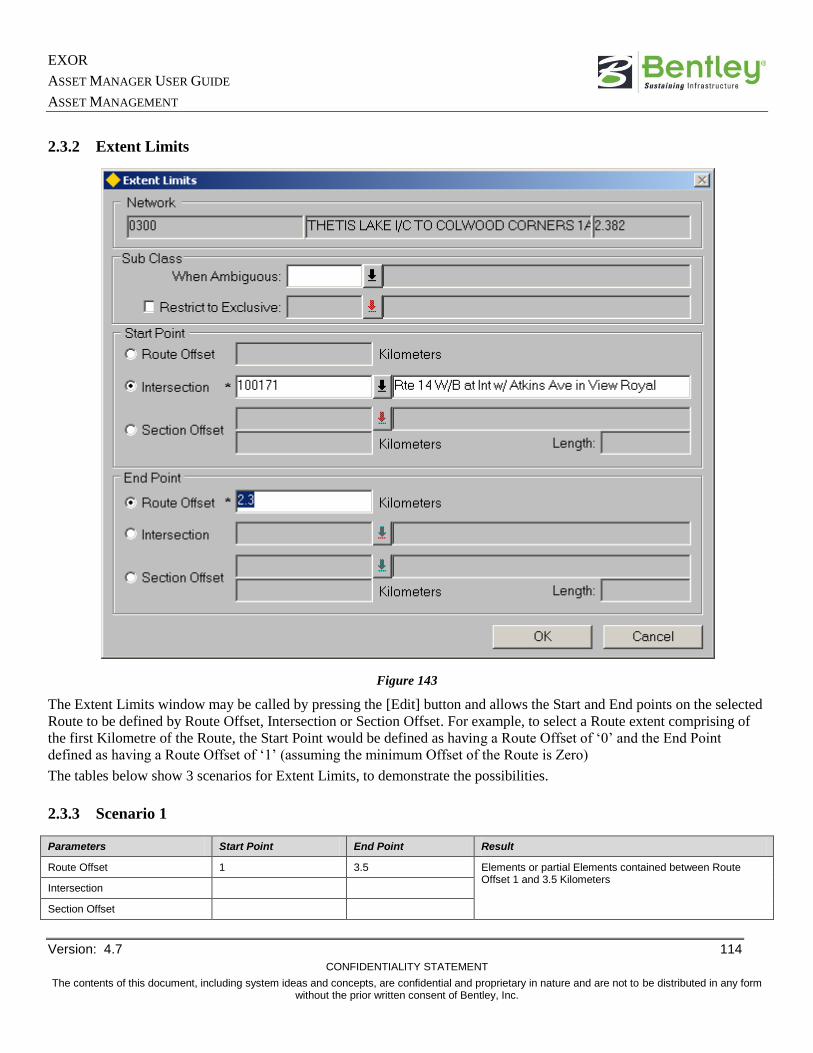
EXOR
ASSET MANAGER USER GUIDE
ASSET MANAGEMENT
Version: 4.7 114
CONFIDENTIALITY STATEMENT
The contents of this document, including system ideas and concepts, are confidential and proprietary in nature and are not to be distributed in any form without the prior written consent of Bentley, Inc.
2.3.2 Extent Limits
Figure 143
The Extent Limits window may be called by pressing the [Edit] button and allows the Start and End points on the selected
Route to be defined by Route Offset, Intersection or Section Offset. For example, to select a Route extent comprising of
the first Kilometre of the Route, the Start Point would be defined as having a Route Offset of ‘0’ and the End Point
defined as having a Route Offset of ‘1’ (assuming the minimum Offset of the Route is Zero)
The tables below show 3 scenarios for Extent Limits, to demonstrate the possibilities.
2.3.3 Scenario 1
Parameters Start Point End Point Result
Route Offset 1 3.5 Elements or partial Elements contained between Route Offset 1 and 3.5 Kilometers
Intersection
Section Offset

EXOR
ASSET MANAGER USER GUIDE
ASSET MANAGEMENT
Version: 4.7 115
CONFIDENTIALITY STATEMENT
The contents of this document, including system ideas and concepts, are confidential and proprietary in nature and are not to be distributed in any form without the prior written consent of Bentley, Inc.
2.3.4 Scenario 2
Parameters Start Point End Point Result
Route Offset 0.24 Elements or partial Elements contained between the Intersection at Node 82730 and Route Offset 0.24
Intersection 082730
Section Offset
2.3.5 Scenario 3
Parameters Start Point End Point Result
Route Offset 5.6 Elements or partial Element contained between 35m along Element H004/1-S and Route Offset 5.6 Kilometers
Intersection
Section Offset H004/1-S
35
2.3.6 Sub Class
Figure 144 - Network Extent Subclass
The ‘Sub Class’ panel of the Extent Limits window allows the User to choose the Sub Class of the Elements, within the
defined extent limits, to be included in the Network Extent. If neither the Sub Class ‘When Ambiguous’ or ‘Restrict to
Exclusive’ field are populated, the Elements of all Sub-Classes within the defined extent limits will be entered into the
Network Extent.
2.3.7 Restrict to Exclusive
Elements may be restricted to a single ‘Exclusive’ Sub Class by selecting the ‘Restrict to Exclusive’ check box and
entering the required Sub-Class in the adjacent field. This will restrict the Elements selected to those that match the
selected Sub Class.
Consider the example below:

EXOR
ASSET MANAGER USER GUIDE
ASSET MANAGEMENT
Version: 4.7 116
CONFIDENTIALITY STATEMENT
The contents of this document, including system ideas and concepts, are confidential and proprietary in nature and are not to be distributed in any form without the prior written consent of Bentley, Inc.
Figure 145
The Route displayed in Figure 145 contains a combination of Network Type Subclasses. A Network Extent is required
within the extent limits shown, but only where the Network Type Sub Class is ‘L’ – Left.
By selecting the ‘Restrict to Exclusive’ checkbox and entering a value of ‘L’ – left in the adjacent field, the Network
Extent will only include Elements (or parts of) with a Network Type Subclass of ‘L’ – Left. Therefore the Network Extent
would include the following Elements:- 3-L, 4-L, 8-L, 9-L
2.3.8 Ambiguous References
Any Ambiguous references within the selected extent limits may be automatically resolved by entering the required
Network Type Sub-Class in the ‘Sub–Class When Ambiguous’ field. For example:
Figure 146
The Route displayed in Figure 146 contains a combination of Network Type Subclasses. A Network Extent is required
within the extent limits shown, but only where the Network Type Sub Class is either ‘S’ – Single or ‘L’ – Left.
By entering a value of ‘L’ – Left in the Sub Class ‘When Ambiguous’ field of the extent limits window, the Network
Extent will include ALL Elements (or parts of) with a Network Type Subclass of ‘S’ – Single and those Elements (or parts
of) with a Network Type Sub Class of ‘L’ – Left. Therefore the Network Extent would include the following Elements:-
1-S, 2-S, 3-L, 4-L, 5-S, 8-L, 9-L, 12-S

EXOR
ASSET MANAGER USER GUIDE
ASSET MANAGEMENT
Version: 4.7 117
CONFIDENTIALITY STATEMENT
The contents of this document, including system ideas and concepts, are confidential and proprietary in nature and are not to be distributed in any form without the prior written consent of Bentley, Inc.
When the Start and End parameters have been defined press the [OK] button on the Extent Limits window.
Network (Display Only)
The Unique Route reference description and maximum Offset of the Route will be displayed.
Sub Class When Ambiguous (Optional)
Enter the required Network Element Sub Class for Elements that should be selected if any ambiguity arises.
Sub Class –Restrict to Exclusive (Optional)
Enter the required Network Element Sub Class to which the selection should be restricted.
2.3.9 Start Point
Select one of the following Radio button to define the Start Point along the selected Route. The default selection is by
Route Offset.
Route Offset
Enter the Route Offset for the Start Point. This should be entered in the unit of measurement defined for the selected
Group or Network Type. The defined Unit will be displayed adjacent to the Route Offset measure.
Intersection (List)
Enter the Node point of the Intersection for the Start Point. The list of values will display all the Intersection Node details
for the selected Route.
Section Offset (List)
Enter the Unique Element reference for the Start Point. The Element description will be displayed in the adjacent field.
The list of values will display all the Network Element within the selected Route.
Enter the Element Offset in the unit of measurement defined for the Datum Element in Network Types–NM0002. The
measured length of the Element will be displayed in the adjacent field.
2.3.10 End Point
Select one of the following Radio button to define the Start Point along the selected Route. The default selection is by
Route Offset
Route Offset
Enter the Route Offset for the End Point. This should be entered in the unit of measurement defined for the selected
Group or Network Type. The defined Unit will be displayed adjacent to the Route Offset measure.
Intersection (List)
Enter the Node point of the Intersection for the End Point. The list of values will display all the Intersection Node details
for the selected Route.

EXOR
ASSET MANAGER USER GUIDE
ASSET MANAGEMENT
Version: 4.7 118
CONFIDENTIALITY STATEMENT
The contents of this document, including system ideas and concepts, are confidential and proprietary in nature and are not to be distributed in any form without the prior written consent of Bentley, Inc.
Section Offset (List)
Enter the Unique Element reference for the End Point. The Element description will be displayed in the adjacent field.
The list of values will display all the Network Element within the selected Route.
Enter the Element Offset in the unit of measurement defined for the Datum Element in Network Types–NM0002. The
measured length of the Element will be displayed in the adjacent field.
Once the required Network has been selected press the [Next >] button to continue with the selection process of the Assets
on Route Query or [Cancel] to close the module. This will display the 'Reference Tab' from where the Reference Event
will be selected.

EXOR
ASSET MANAGER USER GUIDE
ASSET MANAGEMENT
Version: 4.7 119
CONFIDENTIALITY STATEMENT
The contents of this document, including system ideas and concepts, are confidential and proprietary in nature and are not to be distributed in any form without the prior written consent of Bentley, Inc.
2.3.11 Step 2–Reference Event
Figure 147
The Reference Tab allows the Reference Event to be selected. This will be the Event that all selected Assets will have
their relative Offset measure value calculated against. The allowable options are:
Selected Network
Items of Asset Type
Specific Asset Item
Note: If a value has been specified for Product Option DEFITEMTYP or the User Option of the same name has defined
for the User the default Reference Method will be 'Items of Asset Type', otherwise the 'Selected Network' option
will be defaulted.
Reference negatively until first item found
This checkbox affects the way in which relative Offset measures are calculated when referencing to an Asset Type or
specific Asset Item. If selected when an Asset is being referenced against an Asset Type and no Item of that Type
precedes the Asset or the Asset is being referenced against a specific Item which is located further along the Route, the
relative Offset will be calculated as a negative distance to the Reference Item, i.e., the distance back from the Reference
Item to the Asset. If unchecked the Offset measure would be calculated as the distance from the Start of the selected
Network.

EXOR
ASSET MANAGER USER GUIDE
ASSET MANAGEMENT
Version: 4.7 120
CONFIDENTIALITY STATEMENT
The contents of this document, including system ideas and concepts, are confidential and proprietary in nature and are not to be distributed in any form without the prior written consent of Bentley, Inc.
Figure 148vshows an example of a point Asset being referenced against another point item. If the 'Reference negatively…'
checkbox was selected the relative Offset would be calculated as -20. If the checkbox was unselected the relative Offset
would be measured from the start of the selected Network and therefore have a value of 10.
Figure 148
2.3.12 Referencing against the Selected Network
When referencing against the selected Network 2 sets of Offset measurements are available for each Item matching the
selection criteria defined in Step 4 of the Wizard. These are the 'True' Route Start and End Offsets and the Reference Start
and End Offsets. The Reference Start and End Offsets are calculated as the measured distance from the Start of the
selected Network to the Start and End of the Item respectively.
Consider the following examples.
2.3.13 Example 1
Figure 149 shows a continuous Asset that is located on a Route between Offsets 13 to 25, the minimum Route Offset is 0.
Figure 149
The Entire Route has been selected. The Route Start and End Offset and Reference Start and End Offset measures for the
Item would be calculated as follows:
Route Start 13
Route End 25
Reference Start Offset 13 (measured distance from start of selected Network)
Reference End Offset 25 (measured distance from start of selected Network)

EXOR
ASSET MANAGER USER GUIDE
ASSET MANAGEMENT
Version: 4.7 121
CONFIDENTIALITY STATEMENT
The contents of this document, including system ideas and concepts, are confidential and proprietary in nature and are not to be distributed in any form without the prior written consent of Bentley, Inc.
2.3.14 Example 2
In this example the minimum Route Offset is 20, i.e., the Route has been rescaled with a Start Offset of 20. Figure 150
shows a continuous Asset that is located on a Route between Offsets 33 to 45.
Figure 150
The Entire Route has been selected. The Route Start and End Offset and Reference Start and End Offset measures for the
Item would be calculated as follows:
Route Start 33
Route End 45
Reference Start Offset 13 (measured distance from start of selected Network)
Reference End Offset 25 (measured distance from start of selected Network)
2.3.15 Example 3
In this example the selected Route has been filtered to a display range of between Offsets 10 and 30 as shown in Figure
151. A continuous Asset that is located on the Route between Offsets 13 to 25 is being referenced. The minimum Route
Offset is 0.
Figure 151
The Route Start and End Offset and Reference Start and End Offset measures for the Item would be calculated as follows:
Route Start 13
Route End 25
Reference Start Offset 3 (measured distance from start of selected Network)
Reference End Offset 15 (measured distance from start of selected Network)
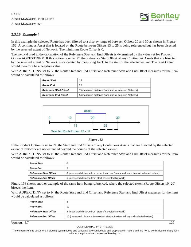
EXOR
ASSET MANAGER USER GUIDE
ASSET MANAGEMENT
Version: 4.7 122
CONFIDENTIALITY STATEMENT
The contents of this document, including system ideas and concepts, are confidential and proprietary in nature and are not to be distributed in any form without the prior written consent of Bentley, Inc.
2.3.16 Example 4
In this example the selected Route has been filtered to a display range of between Offsets 20 and 30 as shown in Figure
152. A continuous Asset that is located on the Route between Offsets 13 to 25 is being referenced but has been bisected
by the selected extent of Network. The minimum Route Offset is 0.
The method used in the calculation of the Reference Start and End Offsets is determined by the value set for Product
Option AOREXTDINV. If this option is set to 'Y', the Reference Start Offset of any Continuous Assets that are bisected
by the selected extent of Network, is calculated by measuring 'back' to the start of the selected extent. The Start Offset
would therefore be a negative value.
With AOREXTDINV set to 'Y' the Route Start and End Offset and Reference Start and End Offset measures for the Item
would be calculated as follows:
Route Start 13
Route End 25
Reference Start Offset 7 (measured distance from start of selected Network)
Reference End Offset 5 (measured distance from start of selected Network)
Figure 152
If the Product Option is set to 'N', the Start and End Offsets of any Continuous Assets that are bisected by the selected
extent of Network are not extended beyond the bounds of the selected extent.
With AOREXTDINV set to 'N' the Route Start and End Offset and Reference Start and End Offset measures for the Item
would be calculated as follows:
Route Start 0
Route End 5
Reference Start Offset 0 (measured distance from extent start not 'measured back' beyond selected extent)
Reference End Offset 5 (measured distance from start of selected Network)
Figure 153 shows another example of the same Item being referenced, where the selected extent (Route Offsets 10 -20)
bisects the Item.
With AOREXTDINV set to 'N' the Route Start and End Offset and Reference Start and End Offset measures for the Item
would be calculated as follows:
Route Start 3
Route End 10
Reference Start Offset 3 (measured distance from start of selected Network)
Reference End Offset 10 (measured distance from extent start not extended beyond selected extent)

EXOR
ASSET MANAGER USER GUIDE
ASSET MANAGEMENT
Version: 4.7 123
CONFIDENTIALITY STATEMENT
The contents of this document, including system ideas and concepts, are confidential and proprietary in nature and are not to be distributed in any form without the prior written consent of Bentley, Inc.
Figure 153
Refer the General System Admin Guide for further details on Product and User Options.
Note: The [Cancel] button will be replaced with a [Current Results] button when the Wizard is recalled from the Assets
on Route Results window. If pressed the current set of results will be redisplayed. Any changes made to any of
the selection parameters will be disregarded.
To reselect the required Network press the [< Back] button or press the 'Network' Tab'.
2.3.17 Referencing against Items of an Asset Type
If the 'Items of an Asset Type' option is selected Asset Items will have their relative Offset measure calculated as the
distance from the nearest preceding Asset of the selected Type. If no preceding Items of the Reference Type exist on the
selected Network, the relative Offset measure will be calculated as the distance to the nearest subsequent Asset of the
selected Reference Type. This Offset measure will be displayed as a negative value, e.g.. the Item is located 20m before
the Reference Asset. Alternatively, if no preceding Items of the Reference Type exist the relative Offset measure may be
calculated from the start of the selected Network (as described on page 120) by un-checking the 'Reference negatively
until first Item found' checkbox on the 'Reference Tab'.
The list of allowable Asset Types will be determined by the Role based security imposed on the Asset Types and User and
may include 'Foreign Table' Asset Types.
A default Referencing Asset Type may be defined by entering the required Asset Type for Product or User Option
DEFITEMTYP. If a value has been entered in the User Option this will take precedence over the Product Option value.
Refer the General System Admin Guide for further details on Product and User Options.
The selected Reference Asset Type may be filtered using the 'Assets Tab' to restrict those Items of the selected Asset Type
that are used as Reference Items. For example, if an Asset Type of SIGN was selected, Asset Items would be measured
relative to the nearest preceding Item of type SIGN as described above. However, if relative Offset measures were only
required relative to 'STOP' Signs a filter could be applied so as only those SIGN items where the attribute of TYPE
equaled STOP are displayed and used as Reference Items. If no filter is required against the selected Asset Type, the Type
does not need to be included in the selection criteria entered in the 'Asset Tab' when selecting the display items.
Relative Offset measures are calculated for each of the displayed Items as follows:
Distance from Start of Item to Start of Reference Item
Distance from End of Item to Start of Reference Item
Distance from Start of Item to End of Reference Item
Distance from End of Item to End of Reference Item
The Start and End Offsets for an Item relative to the Start of the selected Network is also displayed as described on page
120.
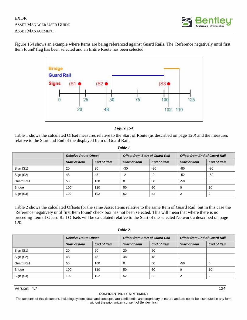
EXOR
ASSET MANAGER USER GUIDE
ASSET MANAGEMENT
Version: 4.7 124
CONFIDENTIALITY STATEMENT
The contents of this document, including system ideas and concepts, are confidential and proprietary in nature and are not to be distributed in any form without the prior written consent of Bentley, Inc.
Figure 154 shows an example where Items are being referenced against Guard Rails. The 'Reference negatively until first
Item found' flag has been selected and an Entire Route has been selected.
Figure 154
Table 1 shows the calculated Offset measures relative to the Start of Route (as described on page 120) and the measures
relative to the Start and End of the displayed Item of Guard Rail.
Table 1
Relative Route Offset Offset from Start of Guard Rail Offset from End of Guard Rail
Start of Item End of Item Start of Item End of Item Start of Item End of Item
Sign (S1) 20 20 -30 -30 -80 -80
Sign (S2) 48 48 -2 -2 -52 -52
Guard Rail 50 100 0 50 -50 0
Bridge 100 110 50 60 0 10
Sign (S3) 102 102 52 52 2 2
Table 2 shows the calculated Offsets for the same Asset Items relative to the same Item of Guard Rail, but in this case the
'Reference negatively until first Item found' check box has not been selected. This will mean that where there is no
preceding Item of Guard Rail Offsets will be calculated relative to the Start of the selected Network a described on page
120.
Table 2
Relative Route Offset Offset from Start of Guard Rail Offset from End of Guard Rail
Start of Item End of Item Start of Item End of Item Start of Item End of Item
Sign (S1) 20 20 20 20
Sign (S2) 48 48 48 48
Guard Rail 50 100 0 50 -50 0
Bridge 100 110 50 60 0 10
Sign (S3) 102 102 52 52 2 2

EXOR
ASSET MANAGER USER GUIDE
ASSET MANAGEMENT
Version: 4.7 125
CONFIDENTIALITY STATEMENT
The contents of this document, including system ideas and concepts, are confidential and proprietary in nature and are not to be distributed in any form without the prior written consent of Bentley, Inc.
The location of the Reference Asset Items of the selected Type are highlighted on the graphical Strip Map on the Assets
on Route Results window by a Red coloured marker on the base line. The location of the current Reference Item is
highlighted by a yellow coloured marker. Figure 155 shows an example where SIGN items are the Reference Type.
Figure 155
Items of the selected Reference Asset Type are highlighted in Green in the Assets multirow block of the Results window
with the currently selected display Item being shown in yellow. Figure 156 shows an example where the Reference Asset
Type is 'GR-Guard Rail' and the current display item is a SIGN.
Figure 156
Once the required Reference Event has been selected press the [Next >] button to continue with the selection process of
the Assets on Route Query or [Cancel] to close the module. This will call the 'Display Tab' from where the Display Items
may be selected.
Note: The [Cancel] button will be replaced with a [Current Results] button when the Wizard is recalled from the Assets
on Route Results window. If pressed the current set of results will be redisplayed. Any changes made to any of
the selection parameters will be disregarded.
To reselect the required Network press the [< Back] button or press the 'Network' Tab'.

EXOR
ASSET MANAGER USER GUIDE
ASSET MANAGEMENT
Version: 4.7 126
CONFIDENTIALITY STATEMENT
The contents of this document, including system ideas and concepts, are confidential and proprietary in nature and are not to be distributed in any form without the prior written consent of Bentley, Inc.
2.3.18 Referencing against a Specific Asset Item
If the 'Specific Asset Item' option is selected Asset Items will have their relative Offset measure calculated as the distance
from a specifically selected. Offset measures for the displayed Items are calculated relative to the specifically selected
Asset Item in the same manner as described on pages 123 to 125.
A default Referencing Asset Type may be defined by entering the required Asset Type for Product or User Option
DEFITEMTYP. If a value has been entered in the User Option this will take precedence over the Product Option value.
Refer the General System Admin Guide for further details on Product and User Options.
To select a specific Asset Item enter the Asset Type or press the [Drop Down List] button adjacent to the field and select
the required Type from the List of Values. The list of allowable Asset Types will be determined by the Role based
security imposed on the Asset Types and User and may include 'Foreign Table' Asset Types.
If known, enter the Primary key of the required Asset. If this is unknown press the [Drop Down List] button adjacent to
the field. This will call the 'Find Assets' window (see page 155), which will allow the required item to be queried and
selected. Once selected the Primary Key and Description of the selected Item will be displayed.
Once the required Reference Event has been selected press the [Next >] button to continue with the selection process of
the Assets on Route Query or [Cancel] to close the module. This will call the 'Display Tab' from where the Display Items
may be selected.
Note: The [Cancel] button will be replaced with a [Current Results] button when the Wizard is recalled from the Assets
on Route Results window. If pressed the current set of results will be redisplayed. Any changes made to any of
the selection parameters will be disregarded.
To reselect the required Network press the [< Back] button or press the 'Network' Tab'.

EXOR
ASSET MANAGER USER GUIDE
ASSET MANAGEMENT
Version: 4.7 127
CONFIDENTIALITY STATEMENT
The contents of this document, including system ideas and concepts, are confidential and proprietary in nature and are not to be distributed in any form without the prior written consent of Bentley, Inc.
2.3.19 Step 3–Display Items
Figure 157
The next stage in defining the Assets on Route query is to define the Items and Attributes that will be displayed on the
Assets on Route Results window. This is done using the 'Display Tab' of the Assets on Route Wizard.
Display Items are selected using either a saved PBI query (see page 190) or by defining a new query in the 'Assets Tab' of
the Assets on Route Wizard.
Default (Radio Button)
Each User may have a Default PBI query to use as the selection criteria for choosing the Display Items. A PBI may be
defined as the User default query for use on Assets on Route by pressing the [AR] button on the PBI Query Toolbar (see
page 202) or by selecting the 'Set new PBI query as default' check box if a new PBI query is created via the 'Asset Tab' on
the Asset on Route wizard (see page 134). If no User default PBI query has been defined this option is unavailable.
PBI (Radio Button)
Select this option to use a saved PBI query. Enter the Unique of the PBI if known or press the [Drop Down List] button
and select the required PBI from the List of Values. The PBI Name and description will be displayed.

EXOR
ASSET MANAGER USER GUIDE
ASSET MANAGEMENT
Version: 4.7 128
CONFIDENTIALITY STATEMENT
The contents of this document, including system ideas and concepts, are confidential and proprietary in nature and are not to be distributed in any form without the prior written consent of Bentley, Inc.
Choose (Radio Button)
Select this option to define a 'temporary' filter using the 'Assets Tab' of the Wizard. This filter may be saved as a new PBI
query if required.
Attribute Set (Optional) List
The flexible Asset Attributes displayed in the Attribute Matrix, Item Attributes panel and any Assets on a Route Reports
called from the AOR Results Window may be 'restricted' to those Attributes of particular interest by specifying an Asset
Attribute Set. This will restrict the Attribute displayed to only those Attributes within the Set.
If an Asset Type is selected for Display but has not been included in the selected Attribute Set only the following 'Fixed'
attributes will be displayed for Assets of that Type.
XSP (if applicable)
Admin Unit
Start Date
Item Description
If no Attribute Set is selected All attributes of the selected Asset Types will be displayed.
Attribute Sets are created using the Asset Attribute Sets–NM0415 module (refer to the Asset Manager System Admin
Guide).
A User default Asset Attribute Set may be defined within the User Preferences–HIG1840 module (refer to the General
User Guide for more information on User Preferences).
Units for Results (Required, Default) List
Select the Unit of measurement to be used in both the Graphical Strip Map and all Offset measures on the Assets on Route
Results window. The default Unit is that currently set as the Unit Name in the User Preferences module–HIG1840 (see
the General User Guide). Units and there respective Conversion factors are defined using Units and Conversions–
HIG1820 (refer to the General System Administration Guide).
Distance Point Interval (Default)
Enter the Interval between distance point markers to be used on the Base Line of the graphical Strip Map on the Assets on
Route Results window. A default Distance Point Interval may be set using either Product or User Option DEFAORDPI.
This Interval should be set in the Units of Measurement defined in the 'Units for Results' field. The smaller the Distance
Point Interval the more descriptive the Strip Map will be as displayed Items may appear 'merged' at large Distance Point
Intervals. Figure 158 shows an example of a Strip Map where the Distance Point Interval is set to a value of 0.2 Km

EXOR
ASSET MANAGER USER GUIDE
ASSET MANAGEMENT
Version: 4.7 129
CONFIDENTIALITY STATEMENT
The contents of this document, including system ideas and concepts, are confidential and proprietary in nature and are not to be distributed in any form without the prior written consent of Bentley, Inc.
Figure 158
It can be clearly seen that a total of 9 Items of type SIGN are located at an XSP of RS within the first Kilometre of the
selected Network. Figure 159 shows the same Assets on Route Results window but with the Distance Interval set to 1Km.
Figure 159
Although a greater extent of the selected Network is displayed it is more difficult to distinguish between individual Items.
The Distance Point Interval may be amended and the Strip Map redrawn within the Assets on Route Results window.
Once the Asset Types to be displayed option, Units and Distance Point Interval have been selected press [Next >] to
continue the selection process or [Cancel] to exit the module. To redefine the Reference Event press the [< Back] button.
Note: The [Cancel] button will be replaced with a [Current Results] button when the Wizard is recalled from the Assets
on Route Results window. If pressed the current set of results will be redisplayed. Any changes made to any of
the selection parameters will be disregarded

EXOR
ASSET MANAGER USER GUIDE
ASSET MANAGEMENT
Version: 4.7 130
CONFIDENTIALITY STATEMENT
The contents of this document, including system ideas and concepts, are confidential and proprietary in nature and are not to be distributed in any form without the prior written consent of Bentley, Inc.
2.3.20 Step 4–Assets (Defining Display Items)
Figure 160
This panel of the Assets on Route Wizard allows a query to be defined to select the required Items to be displayed on the
Results window. If either the 'Default' or 'PBI' options have been previously selected on the 'Display Tab' (page 127) a
copy of the PBI Query definition will be displayed. This may be amended if required without affecting the original PBI
query.
If ALL Items of a particular Type are to be displayed, the Item Type should be entered without defining any Attribute
based filter.
If the Reference Event selected (see page 123) was 'Items of an Asset Type' the Asset Type does not need to be entered in
the Asset query, as all Items of the Reference Type will be displayed. However, if only certain Items of the selected Asset
Type are to be used as reference Events a filter may be added. For example, if the Reference Asset Type was SIGN, a
filter may be applied to only display Signs of type STOP. This would mean that only Stop Signs would be displayed and
used as Reference Event features.
When applying an attribute-based filter to an Asset Type each Item Type may be queried on a single Attribute and value
or Multiple Attribute and value combinations. If multiple Attributes are selected the relationship between the Attributes
may be defined as an 'AND' or 'OR' relationship. Attribute criteria may also be nested with 5 levels of nesting available if
required.

EXOR
ASSET MANAGER USER GUIDE
ASSET MANAGEMENT
Version: 4.7 131
CONFIDENTIALITY STATEMENT
The contents of this document, including system ideas and concepts, are confidential and proprietary in nature and are not to be distributed in any form without the prior written consent of Bentley, Inc.
2.3.21 Inv Types Panel
Figure 161
The selected Asset Type and Description will be displayed. To change the Reference Event Asset Type enter the new
Asset Type code or select from the List of Values called by pressing the [Drop Down List] button adjacent to the field.
The list of values will contain a list of Asset Types to which the user has Role based access including any Foreign Table
Asset Types.
Note: If the query is to be restricted by XSP or Admin Unit, the required XSP or Admin Unit value may be added in the
Attribute Panel.
2.3.22 Attributes Panel
Figure 162
The Attributes panel is used to define the Attributes of the selected Item Type to be used in the filter. If multiple
Attributes are selected the relationship between the Attributes may be defined as an 'AND' or 'OR' relationship. Attribute
criteria may also be nested with 5 levels of nesting available if required by using the Pre and Post brackets as required.
Seq (Required)
Enter the sequence number for the Attribute. Attributes values are resolved in the defined sequence order.
Operator (Required) List
Select the required Boolean connector.
Note: The Operator or the Sequence 1 Attribute must always be 'AND'.
Bracket List
If required select the appropriate Pre Bracket.
Attribute (Required) List

EXOR
ASSET MANAGER USER GUIDE
ASSET MANAGEMENT
Version: 4.7 132
CONFIDENTIALITY STATEMENT
The contents of this document, including system ideas and concepts, are confidential and proprietary in nature and are not to be distributed in any form without the prior written consent of Bentley, Inc.
Select the Attribute of the selected Item to be used in the Gazetteer Filter.
Condition (Required) List
Enter the condition for the selected attribute. These are standard Oracle conditions and are set up and maintained using
Domains–HIG9120 and updating the PBI_CONDITION option.
Bracket List
If required select the appropriate Post Bracket.
2.3.23 Values Panel
Figure 163 - Values
This panel is used to define the parameter values for the currently selected Attribute.
Value (Required) (List)
Enter the required ‘Query’ value for the currently selected Attribute. If the attribute values are held in a Domain, the List
of Values may be called and the description of the selected value will be displayed. If the ‘Condition’ entered for the
Attribute is ‘BETWEEN’ enter the second value in the field below.
If a List of Values is called the extended LOV window will be called as shown in Figure 164.
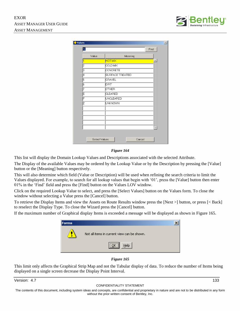
EXOR
ASSET MANAGER USER GUIDE
ASSET MANAGEMENT
Version: 4.7 133
CONFIDENTIALITY STATEMENT
The contents of this document, including system ideas and concepts, are confidential and proprietary in nature and are not to be distributed in any form without the prior written consent of Bentley, Inc.
Figure 164
This list will display the Domain Lookup Values and Descriptions associated with the selected Attribute.
The Display of the available Values may be ordered by the Lookup Value or by the Description by pressing the [Value]
button or the [Meaning] button respectively.
This will also determine which field (Value or Description) will be used when refining the search criteria to limit the
Values displayed. For example, to search for all lookup values that begin with ‘01’, press the [Value] button then enter
01% in the ‘Find’ field and press the [Find] button on the Values LOV window.
Click on the required Lookup Value to select, and press the [Select Values] button on the Values form. To close the
window without selecting a Value press the [Cancel] button.
To retrieve the Display Items and view the Assets on Route Results window press the [Next >] button, or press [< Back]
to reselect the Display Type. To close the Wizard press the [Cancel] button.
If the maximum number of Graphical display Items is exceeded a message will be displayed as shown in Figure 165.
Figure 165
This limit only affects the Graphical Strip Map and not the Tabular display of data. To reduce the number of Items being
displayed on a single screen decrease the Display Point Interval.

EXOR
ASSET MANAGER USER GUIDE
ASSET MANAGEMENT
Version: 4.7 134
CONFIDENTIALITY STATEMENT
The contents of this document, including system ideas and concepts, are confidential and proprietary in nature and are not to be distributed in any form without the prior written consent of Bentley, Inc.
2.3.24 Create a New PBI Query
Figure 166
The Asset query may be saved for future use by saving it as a new PBI Query. To do this press the [Create PBI Query…]
button. This will call the 'New PBI Query Details' window as shown in Figure 166.
To create a new PBI query enter a Unique name for the PBI Query and Description. To set the new PBI query to the User
Default PBI select the Checkbox. When the appropriate details have been entered press the [Create] button. A message
will be displayed when the PBI query has been successfully created.

EXOR
ASSET MANAGER USER GUIDE
ASSET MANAGEMENT
Version: 4.7 135
CONFIDENTIALITY STATEMENT
The contents of this document, including system ideas and concepts, are confidential and proprietary in nature and are not to be distributed in any form without the prior written consent of Bentley, Inc.
2.3.25 Assets on Route Results
Figure 167
The Assets on Route Results window shows the selected Display Items in tabular format in the Assets panel and if
required in a Graphical Strip Map (page 144) which may be displayed by pressing the [Show Strip Map] button. If
Product Option AORSTRMAP is set to Y the Strip Map will be automatically displayed.
Display Items are ordered by Route Offset with the Route Offsets and measure values relative to the selected Reference
Event being displayed in the Offsets panel. The Attributes Tab allows the Attributes of the Display Items to be viewed in
a 'matrix' format Figure 168 shows an example of the Assets Panel with the Attributes matrix active.

EXOR
ASSET MANAGER USER GUIDE
ASSET MANAGEMENT
Version: 4.7 136
CONFIDENTIALITY STATEMENT
The contents of this document, including system ideas and concepts, are confidential and proprietary in nature and are not to be distributed in any form without the prior written consent of Bentley, Inc.
Figure 168
The first 4 columns (3 if XSP is not applicable) display the following 'fixed Attribute' values:
XSP
Admin Unit
Start Date
Item Description
The Attributes of the currently selected Display Item, and if appropriate the Reference Item, are also displayed in the Item
Attributes and the Ref Item Attribute panels respectively.
The Attribute values of the currently selected Display Item may be updated in the Item Attributes panel. To update an
Item the User must have 'Normal' Role based access to the Asset Type and 'Normal' access to the Admin unit of the Asset
Item. Full validation of max, min values, Domain Lists and any Cross Attribute or Cross Item Validation Rules etc, is
carried out when an Attribute value is changed.
Note: No history is kept of the previous Attribute value.
The Asset Items–NM0510 module may be called by pressing the [Expand] button on the menu toolbar or by clicking
in the 'Asset Type' or 'Reference Item' field of the required record and selecting the 'Item Details…' option from the
context menu called by clicking the right mouse button. This will allow the location of the currently selected Item to be
amended if required.
The location of the selected Item, relative to any other LRM’s on which the Item is located is displayed in the Item Route
Location tab. The Datum Element locations for the Item are displayed in the Item Datum Location Tab.
Any associated Documents referenced within Document Manager for an Item may be viewed by selected the required
Item within the tabular Assets panel and pressing the [Document] button on the menu toolbar. This will call the
Document Associations window where any associated documents may be viewed.
Note: Performance may be improved by defining the required Route as the Default Region Of Interest. This will ensure
that only the GIS theme will only be applied to the selected extent of Network. Refer to the Network Manager
User or the General User Guides for more information on Default Region of Interest.

EXOR
ASSET MANAGER USER GUIDE
ASSET MANAGEMENT
Version: 4.7 137
CONFIDENTIALITY STATEMENT
The contents of this document, including system ideas and concepts, are confidential and proprietary in nature and are not to be distributed in any form without the prior written consent of Bentley, Inc.
2.3.26 Region of Interest Panel
Figure 169
The Region Of Interest Panel displays Network Details selected in the in the Network Tab on the Assets on Route Wizard.
To select a new Region of Interest press the [< Back To Criteria] button at the bottom the Results window. This will call
the Assets on Route Wizard from where the new Region Of Interest may be selected.
Route/Extent Unique and Description
The Unique and Description of the selected Network
Entire
If the Entire Route has been selected, i.e., no discreet Start and End points have been defined for the selected Network,
this checkbox will be ticked.
Start/End
If discreet Start and End points have been defined for the selected Network these will be displayed. The Units of
measurement will be determined by the Units associated with the Network Type of the Group.
Ambig SC
If a Sub Class has been selected to resolve any ambiguity it will be displayed.
Reference Event
The selected Reference Event will be displayed. The following examples display the possibilities:
Reference against a specific Item. The Item Type and
Primary Key will be displayed
Reference against an Asset Type. The Type will be
displayed
Reference against the selected Network. The Network
Unique will be displayed

EXOR
ASSET MANAGER USER GUIDE
ASSET MANAGEMENT
Version: 4.7 138
CONFIDENTIALITY STATEMENT
The contents of this document, including system ideas and concepts, are confidential and proprietary in nature and are not to be distributed in any form without the prior written consent of Bentley, Inc.
2.3.27 Asset Panel
Figure 170
The Assets panel displays the Asset Items along with the Route Start and End Offsets (ordered by Route Offset) along
with the relative Offset Reference measures as described earlier, displayed in the Offsets Panel.
An Asset Attribute 'matrix' panel may be displayed in place of the 'Offsets' panel by pressing the 'Attributes Tab'. An
example of the Assets panel with the Attributes matrix displayed is shown in Figure 171.
Figure 171
The Assets may be viewed by scrolling through the list using either the Vertical Scroll bar or by pressing the arrow keys
on the Keyboard. If whilst scrolling through the Assets the current Items Start Offset is outside the extent of Network
shown on the Strip Map Base Line, the Base Line will scroll as appropriate provided the 'Auto Zoom' check box is
selected. If the checkbox is not selected the Strip Map will remain static. To move the Strip Map Base Line to display the
selected Item press the [Zoom to Selected Asset] button.
It is also possible to Jump to any Display Item on the selected Network by pressing the [Jump to Item…] button. This will
display a list of all the selected Display Items on the selected Network as shown here:

EXOR
ASSET MANAGER USER GUIDE
ASSET MANAGEMENT
Version: 4.7 139
CONFIDENTIALITY STATEMENT
The contents of this document, including system ideas and concepts, are confidential and proprietary in nature and are not to be distributed in any form without the prior written consent of Bentley, Inc.
Figure 172
The list is ordered by the start Offset relative to the selected Network and displays the following details for each Display
Item:
Asset Type and Type Description
Route Start Offset
Route End Offset
Distance from Start of the Item to Start of Reference Event (*)
Distance from End of Item to Start of Reference Event (*)
Distance from Start of Item to End of Reference Event (*)
Distance from End of Item to End of Reference Event (*)
(*) Refer to pages 120 – 126 for calculation methods
To jump to the selected Item press the [OK] button. The selected Item will be displayed in the tabular Assets panel and if
the Auto Zoom checkbox is selected the Strip Map will zoom to the selected Item.
When the selected Reference Event is either Assets of a Selected Type or a specific Asset Item, the Reference Item
Type(s) are displayed in green
The following details are displayed for each of the display Items.
Asset Type
The Asset Type and Description
Start and End Offsets
This is the Route Start and End Offsets of the Item irrespecive of the Route extent selected, i.e., it is the 'true' Route offset.

EXOR
ASSET MANAGER USER GUIDE
ASSET MANAGEMENT
Version: 4.7 140
CONFIDENTIALITY STATEMENT
The contents of this document, including system ideas and concepts, are confidential and proprietary in nature and are not to be distributed in any form without the prior written consent of Bentley, Inc.
2.3.28 Offsets Panel
Reference Item
The Primary Key of the Reference Item, i.e., the Asset to which the currently selected Item is being referenced, will be
displayed. If the Reference Event is the selected Network the Unique of the Route will be displayed.
Reference Start Offsets (Start and End)
The Reference Start Offsets are the measured Offsets of the Start and End of the selected Item relative to the Start of the
current Reference Event. For more detailed information on how the Offsets are measured refer to page 120 (Referencing
to the selected Network) and page 123 (Referencing against an Asset).
Reference End Offsets (Start and End)
The Reference End Offsets are the measured Offsets of the Start and End of the selected Item relative to the End of the
current Reference Event. For more detailed information on how the Offsets are measured refer to page 120 (Referencing
to the selected Network) and page 123 (Referencing against an Asset).
To redefine any of the criteria used within the Assets on Route query press the [< Back to Criteria] button. This will recall
the Assets on Route Wizard where any of the criteria may be amended.
2.3.29 Item Attributes Panel
Figure 173
The Item Attributes panel displays the Attributes of the currently selected Display Item. If an Asset Attribute set has been
specified (page 128) only the flexible Attributes associated with the Attribute set will be displayed for an Asset Type
along with the following 'fixed' Attributes:
XSP (if applicable)
Admin Unit
Start Date
Item Description
The Attribute values of an Item may be updated using this panel only if the User has been granted 'Normal' access to any
Role associated with the Asset Type (refer the Asset Manager System Admin Guide for more details) and 'Normal' access
to the Admin Unit of the Asset Item (refer to the General System Admin Guide for more details). Full validation of max,
min values, Domain Lists and any Cross Attribute or Cross Item Validation Rules etc, is carried out when an Attribute
value is changed.
Note: No history is kept of the previous Attribute value.

EXOR
ASSET MANAGER USER GUIDE
ASSET MANAGEMENT
Version: 4.7 141
CONFIDENTIALITY STATEMENT
The contents of this document, including system ideas and concepts, are confidential and proprietary in nature and are not to be distributed in any form without the prior written consent of Bentley, Inc.
2.3.30 Navigator Button
If an asset has data linked to it from other functions within the system, for example child assets, defects, enquiries or has
been linked to a scheme or a cyclic schedule the navigator form will be displayed showing the relevant associations for
the selected asset in the form of a hierarchy. This may be viewed using the [Navigator] button. An example of an assets
hierarchy is shown here:
Figure 174
Navigator displays a summary of the associated records, double clicking on any of the records in the tree will display the
full details of the record in the appropriate form.
Full details of the use of navigator can be found in the Navigator and Query Builder User Guide.
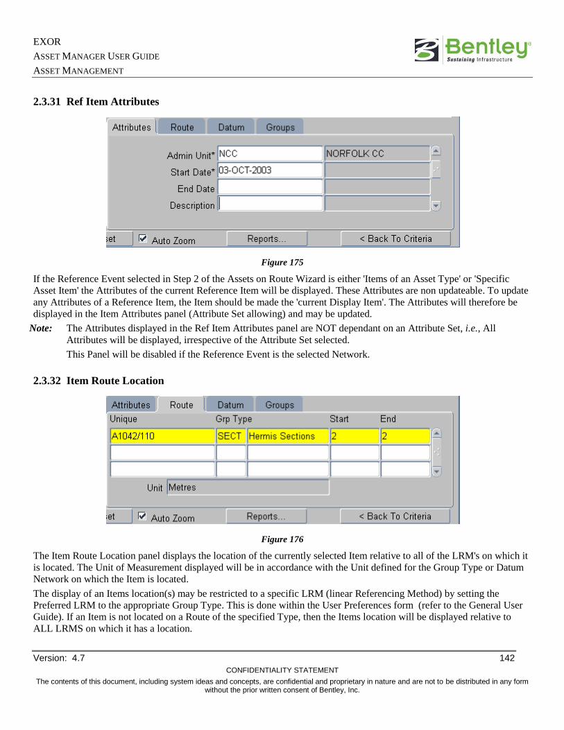
EXOR
ASSET MANAGER USER GUIDE
ASSET MANAGEMENT
Version: 4.7 142
CONFIDENTIALITY STATEMENT
The contents of this document, including system ideas and concepts, are confidential and proprietary in nature and are not to be distributed in any form without the prior written consent of Bentley, Inc.
2.3.31 Ref Item Attributes
Figure 175
If the Reference Event selected in Step 2 of the Assets on Route Wizard is either 'Items of an Asset Type' or 'Specific
Asset Item' the Attributes of the current Reference Item will be displayed. These Attributes are non updateable. To update
any Attributes of a Reference Item, the Item should be made the 'current Display Item'. The Attributes will therefore be
displayed in the Item Attributes panel (Attribute Set allowing) and may be updated.
Note: The Attributes displayed in the Ref Item Attributes panel are NOT dependant on an Attribute Set, i.e., All
Attributes will be displayed, irrespective of the Attribute Set selected.
This Panel will be disabled if the Reference Event is the selected Network.
2.3.32 Item Route Location
Figure 176
The Item Route Location panel displays the location of the currently selected Item relative to all of the LRM's on which it
is located. The Unit of Measurement displayed will be in accordance with the Unit defined for the Group Type or Datum
Network on which the Item is located.
The display of an Items location(s) may be restricted to a specific LRM (linear Referencing Method) by setting the
Preferred LRM to the appropriate Group Type. This is done within the User Preferences form (refer to the General User
Guide). If an Item is not located on a Route of the specified Type, then the Items location will be displayed relative to
ALL LRMS on which it has a location.

EXOR
ASSET MANAGER USER GUIDE
ASSET MANAGEMENT
Version: 4.7 143
CONFIDENTIALITY STATEMENT
The contents of this document, including system ideas and concepts, are confidential and proprietary in nature and are not to be distributed in any form without the prior written consent of Bentley, Inc.
2.3.33 Item Datum Location
Figure 177
The 'Item Datum Location' panel displays the location of the currently selected Display Item relative to the Datum
Elements on which it is located. The Unit of Measurement will be that which has been defined for the appropriate Datum
Network Type in the Network Types–NM0002 module (refer to the Network Manager System Admin Guide).
2.3.34 Item Groups Location
Figure 178
The ‘Groups’ location panel displays the Groups (non linear Groups of Sections) on which the currently selected Display
Item is either partially or wholly located. As these Group Types are non-linear no offset measures are displayed.

EXOR
ASSET MANAGER USER GUIDE
ASSET MANAGEMENT
Version: 4.7 144
CONFIDENTIALITY STATEMENT
The contents of this document, including system ideas and concepts, are confidential and proprietary in nature and are not to be distributed in any form without the prior written consent of Bentley, Inc.
2.3.35 Graphical Strip Map
Figure 179
The Strip Map provides a straight line interpretation of the selected Network and depicts the selected Display Items in
their relative linear Offset against a Base Line. The Base Line is divided into Distance Points with a total of 8 being
displayed on a single screen. The Distance Point Interval will have been defined in the 'Display Tab' of the Assets on
Route Wizard but can be reset by changing the value in the 'Distance Point Interval' field on the Strip Map.
The Interval is measured in the Units of Measurement defined in the 'Display Tab' of the Wizard. The combination of the
Distance Point Interval and the Units of Measurement used, determine the extent of Network displayed on a single screen.
For example, if the Interval was set to 5 and the Units were in Kilometres a total of 40 Km of Network would be visible
on a single screen.
Figure 180
To move along the Base Line press the [<] or [>] arrow buttons on the Base Line scroll bar (Figure 180). This will move
the Base Line 1 distance point interval for each click. Alternatively to jump to a specific Offset enter the required Offset
value in the Scroll Bar field and press return on the Keyboard. This will move the start point of the Base Line to the
appropriate Offset.
The selected Display Asset Types are subdivided into Asset Type/XSP combinations, with each combination being
displayed on separate rows within the Strip Map. For example if an Item Type of SIGN was selected and SIGN Items
existed in 2 different XSP's within the selected extent of Network, each SIGN/XSP combination would be displayed on
separate rows. This 'stacking' of different Asset Type/XSP combinations ensures that overlapping Items of different Types
or XSP's do not become obscured.
Figure 181
Asset Type/XSP combinations are ordered from top of page to bottom alphabetically by XSP then Asset Type, with those
Asset Type which do not have associated XSP values appearing at the bottom of the 'stack'. The Strip Map be scrolled
vertically to view other available Asset Type/XSP combinations by pressing the [Up] or [Down] buttons below the 'stack'
legend (Figure 181).
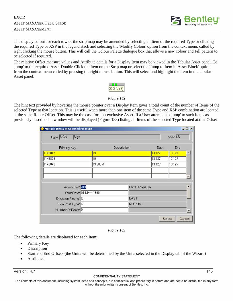
EXOR
ASSET MANAGER USER GUIDE
ASSET MANAGEMENT
Version: 4.7 145
CONFIDENTIALITY STATEMENT
The contents of this document, including system ideas and concepts, are confidential and proprietary in nature and are not to be distributed in any form without the prior written consent of Bentley, Inc.
The display colour for each row of the strip map may be amended by selecting an Item of the required Type or clicking
the required Type or XSP in the legend stack and selecting the 'Modify Colour' option from the context menu, called by
right clicking the mouse button. This will call the Colour Palette dialogue box that allows a new colour and Fill pattern to
be selected if required.
The relative Offset measure values and Attribute details for a Display Item may be viewed in the Tabular Asset panel. To
'jump' to the required Asset Double Click the Item on the Strip map or select the 'Jump to Item in Asset Block' option
from the context menu called by pressing the right mouse button. This will select and highlight the Item in the tabular
Asset panel.
Figure 182
The hint text provided by hovering the mouse pointer over a Display Item gives a total count of the number of Items of the
selected Type at that location. This is useful when more than one item of the same Type and XSP combination are located
at the same Route Offset. This may be the case for non-exclusive Asset. If a User attempts to 'jump' to such Items as
previously described, a window will be displayed (Figure 183) listing all Items of the selected Type located at that Offset
Figure 183
The following details are displayed for each Item:
Primary Key
Description
Start and End Offsets (the Units will be determined by the Units selected in the Display tab of the Wizard)
Attributes

EXOR
ASSET MANAGER USER GUIDE
ASSET MANAGEMENT
Version: 4.7 146
CONFIDENTIALITY STATEMENT
The contents of this document, including system ideas and concepts, are confidential and proprietary in nature and are not to be distributed in any form without the prior written consent of Bentley, Inc.
To jump to a specific Item in the tabular Asset panel select the required Item and press the [Select] button or press
[Cancel] to close the window without selecting an Item.
If the selected Reference Event is Asset based, i.e., Items are not be referenced relative to the start of the selected
Network, the location of the Reference Asset Items of the selected Type are highlighted on the Base Line by a Red
coloured marker. A yellow coloured marker highlights the location of the current Reference Item. Figure 184 shows an
example where SIGN items are the Reference Type.
Figure 184
2.3.36 Asset on Route Reports
Several reports are available which relate to the results of an Assets on Route query. The reports may be called directly
from the Network Manager Menu or by pressing the [Reports…] button on the AOR Results window.
When the Reports are called from the Assets on Route Results window a dialogue box will be displayed (Figure 185)
to allow the User to select the required AOR Report and if required the Attribute set for use with the report.
Figure 185
Report (Required) List
Select the required Report from the list of available reports. Full details of the reports available can be found on pages 147
and 151.
Attribute Set (Optional) List
If an Attribute Set has been selected in 'Step 3–Display' of the AOR setup Wizard this will be displayed as the default
Attribute Set. Only those flexible Attributes associated with the Attribute Set will be displayed within the report. The

EXOR
ASSET MANAGER USER GUIDE
ASSET MANAGEMENT
Version: 4.7 147
CONFIDENTIALITY STATEMENT
The contents of this document, including system ideas and concepts, are confidential and proprietary in nature and are not to be distributed in any form without the prior written consent of Bentley, Inc.
Attribute Set selected within the Wizard may be changed for the Reports or even deleted allowing All flexible Attributes
to be displayed.
To run the Report press [Run] or [Cancel] to return to the AOR Results window.
The Report Styles used in these Reports, i.e., Colour Schemes and Logo's etc may be amended using Report Styles–
HIG1850. The current Report Style is set using Product/User Option RPRTSTYLE. For more information refer to the
General System Admin Guide.
2.3.37 NM0562–Assets on a Route Report–By offset
This Report provides a listing of all those Asset Items meeting the selection criteria defined in Step 4- Assets of the AOR
Wizard which are located on the selected Network (Step 1–Network of the AOR Wizard). The Items are ordered in Route
Offset order.
The Offset measures displayed on the Report will be determined by the Reference Event selected in Step 2- Reference of
the AOR Wizard. If the Reference Event is the 'Selected Network' only the Route Start and End Offsets will be displayed.
If either 'Assets of Type' or a 'specific' Item has been selected the Report will also include the Reference Start and end
Offsets.
A 'Description' Column is included within the Report that is a Concatenation of the Attributes (within the selected
Attribute Set if applicable) for each Item. The Attributes may separated with a character which is defined by Product
Option–ATTRLSTSEP. For example, if the Product Option value is set to ',' (Comma) the description string for an Asset
Item may look like– 'W, T,1,WOOD’. The same description String separated with a ':' (Colon) would look like
'W:T:1:WOOD’.
Product Options are defined using the Product Option–HIG9130 module (refer to the General User System Admin Guide).
A summary of the Total Number and Length (if Item Type is continuous) of the each Item Type displayed within the
Report is displayed on the final Report page.
The Report Header includes the following information
Selected Region of Interest
Minimum Route Offset
Maximum Route Offset
Route Length
Start Measure of selected Network
End Measure of selected Network
Units of Measurement for Route
Display Units for Offset measures
The report will be displayed within the Reports Preview window allowing the User to view the Report before Printing.
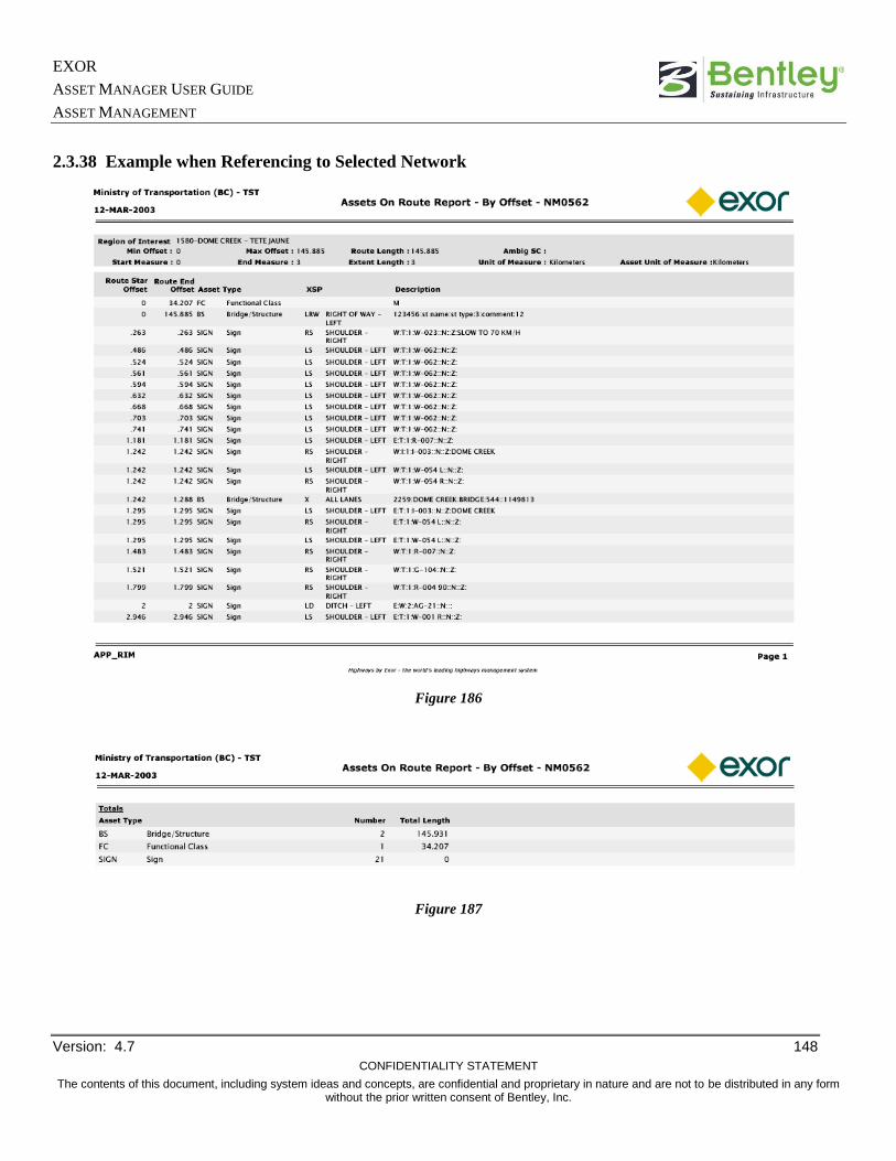
EXOR
ASSET MANAGER USER GUIDE
ASSET MANAGEMENT
Version: 4.7 148
CONFIDENTIALITY STATEMENT
The contents of this document, including system ideas and concepts, are confidential and proprietary in nature and are not to be distributed in any form without the prior written consent of Bentley, Inc.
2.3.38 Example when Referencing to Selected Network
Figure 186
Figure 187
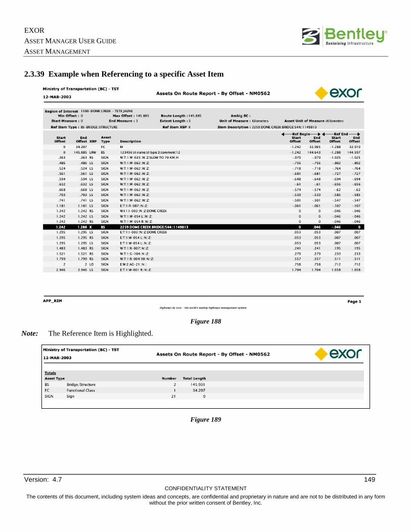
EXOR
ASSET MANAGER USER GUIDE
ASSET MANAGEMENT
Version: 4.7 149
CONFIDENTIALITY STATEMENT
The contents of this document, including system ideas and concepts, are confidential and proprietary in nature and are not to be distributed in any form without the prior written consent of Bentley, Inc.
2.3.39 Example when Referencing to a specific Asset Item
Figure 188
Note: The Reference Item is Highlighted.
Figure 189

EXOR
ASSET MANAGER USER GUIDE
ASSET MANAGEMENT
Version: 4.7 150
CONFIDENTIALITY STATEMENT
The contents of this document, including system ideas and concepts, are confidential and proprietary in nature and are not to be distributed in any form without the prior written consent of Bentley, Inc.
2.3.40 Example when Referencing against Items of another Asset Type
Figure 190
Note: Items of the Reference Type are Highlighted.

EXOR
ASSET MANAGER USER GUIDE
ASSET MANAGEMENT
Version: 4.7 151
CONFIDENTIALITY STATEMENT
The contents of this document, including system ideas and concepts, are confidential and proprietary in nature and are not to be distributed in any form without the prior written consent of Bentley, Inc.
2.3.41 NM0563–Asset on a Route Report–By Type and Offset
This Report provide a listing of all those Asset Items meeting the selection criteria defined in Step 4- Assets of the AOR
Wizard which are located on the selected Network (Step 1–Network of the AOR Wizard). The Items are grouped by Asset
Type and ordered by Route Offset.
The Offset measures displayed on the Report will be determined by the Reference Event selected in Step 2- Reference of
the AOR Wizard. If the Reference Event is the 'Selected Network' only the Route Start and End Offsets will be displayed.
If either 'Assets of Type' or a 'specific' Item has been selected the Report will also include the Reference Start and end
Offsets.
The Attribute Names and Values of those Attributes within the selected Attribute Set (if any) are displayed for each Item.
Note: It is advised that Attribute Sets are used to restrict the display of Attributes to those of particular interest.
A summary of the Total Number and Length (if Item Type is continuous) for each of the Item Types is displayed.
The Report Header includes the following information:
Selected Region of Interest
Minimum Route Offset
Maximum Route Offset
Route Length
Start Measure of selected Network
End Measure of selected Network
Units of Measurement for Route
Display Units for Offset measures
The report will be displayed within the Reports Preview window allowing the User to view the Report before Printing.

EXOR
ASSET MANAGER USER GUIDE
ASSET MANAGEMENT
Version: 4.7 152
CONFIDENTIALITY STATEMENT
The contents of this document, including system ideas and concepts, are confidential and proprietary in nature and are not to be distributed in any form without the prior written consent of Bentley, Inc.
2.3.42 Example when Referencing to Selected Network
Figure 191

EXOR
ASSET MANAGER USER GUIDE
ASSET MANAGEMENT
Version: 4.7 153
CONFIDENTIALITY STATEMENT
The contents of this document, including system ideas and concepts, are confidential and proprietary in nature and are not to be distributed in any form without the prior written consent of Bentley, Inc.
2.3.43 Example when Referencing to a specific Asset Item
Figure 192

EXOR
ASSET MANAGER USER GUIDE
ASSET MANAGEMENT
Version: 4.7 154
CONFIDENTIALITY STATEMENT
The contents of this document, including system ideas and concepts, are confidential and proprietary in nature and are not to be distributed in any form without the prior written consent of Bentley, Inc.
2.3.44 Example when Referencing against Items of another Asset Type
Figure 193

EXOR
ASSET MANAGER USER GUIDE
ASSET MANAGEMENT
Version: 4.7 155
CONFIDENTIALITY STATEMENT
The contents of this document, including system ideas and concepts, are confidential and proprietary in nature and are not to be distributed in any form without the prior written consent of Bentley, Inc.
2.4 Find Assets–NM0570
Figure 194 - Find Assets Menu Option
The Find Assets–NM0570 module allows Assets Items to be queried using their defining Attributes and is based on the
actual Items and not the Items location, allowing Items which are not located on a Network to be easily found. Unlike a
PBI query or Gazetteer Filter, the Find Assets functionality returns the actual Asset Items and not purely their locations.
However, the selection criteria may optionally be restricted to a defined Region of Interest.
The Find Assets module can be used in either ‘Standard’ (the default) or Advanced mode. In ‘Standard’ mode the query is
restricted to a single Asset Type, Attribute and Value combination. This is particularly useful when searching for an Asset
with a known Primary or business Key value.
The ‘Advanced’ mode allows a more complex query to be constructed where each Item Type selected may be queried on
a single Attribute and value or Multiple Attribute and value combinations. If multiple Attributes are selected the
relationship between the Attributes may be defined as an 'AND' or 'OR' relationship. Attribute criteria may also be nested
with 5 levels of nesting available if required.
To select all Items of a particular Asset Type no attribute criteria should be applied, i.e., the only selection criteria entered
is the required Asset Type.

EXOR
ASSET MANAGER USER GUIDE
ASSET MANAGEMENT
Version: 4.7 156
CONFIDENTIALITY STATEMENT
The contents of this document, including system ideas and concepts, are confidential and proprietary in nature and are not to be distributed in any form without the prior written consent of Bentley, Inc.
Figure 195

EXOR
ASSET MANAGER USER GUIDE
ASSET MANAGEMENT
Version: 4.7 157
CONFIDENTIALITY STATEMENT
The contents of this document, including system ideas and concepts, are confidential and proprietary in nature and are not to be distributed in any form without the prior written consent of Bentley, Inc.
2.4.1 Location Panel (Standard and Advanced modes)
Figure 196
All Items (Checkbox)
If this option is selected the Find Assets filter will be based purely on the selection criteria defined and not further
restricted by the location of an Asset. If the option is selected the remaining fields within the Location Panel will be
disabled.
Name
Enter the required Region Of Interest or select from the Gazetteer (refer the Network Manager User guide). If a Default
Region of Interest has been defined using the User Preferences module (General User Guide) it will be automatically
displayed. This may be changed if required.
Description
The description of the selected Region of Interest will be displayed.
If a Linear Group or Route has been selected a filter may be applied so as to return only those Items which meet the
defined selection criteria and are located within the extent of Network between specified Start and End Offsets on the
Route. The default option is to return the entire Route or Linear Group. To restrict the Find Assets query to the extent of
Network between specified Start and End Offsets uncheck the 'Entire' check box and add the required start and end
Offsets as required in the 'Start' and 'End' fields respectively.
If the Start and End Offsets are to be defined relative to an Intersection or Datum Element along the Route the 'Extent
Limits' window (Figure 198) may be called by pressing the [Edit] button.
Note: If an entire Route is required, performance will be enhanced by ensuring the 'Entire' checkbox is selected as
opposed to specifying the minimum and maximum Offsets of the Route.
Entire (Checkbox)
Uncheck this if the Linear Group or Route is to be restricted by Start and End Offsets. This option is only available if a
linear Group or Route is selected.
Start
If the 'Entire' checkbox is unselected, enter the required Start Offset. The default value is the minimum Offset of the
selected Route.
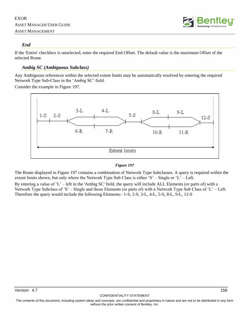
EXOR
ASSET MANAGER USER GUIDE
ASSET MANAGEMENT
Version: 4.7 158
CONFIDENTIALITY STATEMENT
The contents of this document, including system ideas and concepts, are confidential and proprietary in nature and are not to be distributed in any form without the prior written consent of Bentley, Inc.
End
If the 'Entire' checkbox is unselected, enter the required End Offset. The default value is the maximum Offset of the
selected Route.
Ambig SC (Ambiguous Subclass)
Any Ambiguous references within the selected extent limits may be automatically resolved by entering the required
Network Type Sub-Class in the ‘Ambig SC’ field.
Consider the example in Figure 197.
Figure 197
The Route displayed in Figure 197 contains a combination of Network Type Subclasses. A query is required within the
extent limits shown, but only where the Network Type Sub Class is either ‘S’ – Single or ‘L’ – Left.
By entering a value of ‘L’ – left in the 'Ambig SC' field, the query will include ALL Elements (or parts of) with a
Network Type Subclass of ‘S’ – Single and those Elements (or parts of) with a Network Type Sub Class of ‘L’ – Left.
Therefore the query would include the following Elements:- 1-S, 2-S, 3-L, 4-L, 5-S, 8-L, 9-L, 12-S

EXOR
ASSET MANAGER USER GUIDE
ASSET MANAGEMENT
Version: 4.7 159
CONFIDENTIALITY STATEMENT
The contents of this document, including system ideas and concepts, are confidential and proprietary in nature and are not to be distributed in any form without the prior written consent of Bentley, Inc.
2.4.2 Extent Limits
Figure 198
The Extent Limits window may be called by pressing the [Edit] button on the Filter panel and allows the Start and End
points on the selected Route to be defined by Route Offset, Intersection or Section Offset. For example, to select a Route
extent comprising of the first Kilometre of the Route, the Start Point would be defined as having a Route Offset of ‘0’ and
the End Point defined as having a Route Offset of ‘1’ (assuming the minimum Offset of the Route is Zero).
The tables below show 3 scenarios for Extent Limits, to demonstrate the possibilities.
2.4.3 Scenario 1
Parameters Start Point End Point Result
Route Offset 1 3.5 Elements or partial Elements contained between Route Offset 1 and 3.5 Kilometers
Intersection
Section Offset

EXOR
ASSET MANAGER USER GUIDE
ASSET MANAGEMENT
Version: 4.7 160
CONFIDENTIALITY STATEMENT
The contents of this document, including system ideas and concepts, are confidential and proprietary in nature and are not to be distributed in any form without the prior written consent of Bentley, Inc.
2.4.4 Scenario 2
Parameters Start Point End Point Result
Route Offset 0.24 Elements or partial Elements contained between the Intersection at Node 82730 and Route Offset 0.24
Intersection 082730
Section Offset
2.4.5 Scenario 3
Parameters Start Point End Point Result
Route Offset 5.6 Elements or partial Element contained between 35m along Element H004/1-S and Route Offset 5.6 Kilometers
Intersection
Section Offset H004/1-S
35
2.4.6 Sub Class
Figure 199 - Network Extent Subclass
The ‘Sub Class’ panel of the Extent Limits window allows the User to choose the Sub Class of the Elements, within the
defined extent limits, to be included in the Network Extent. If neither the Sub Class ‘When Ambiguous’ or ‘Restrict to
exclusive’ field are populated, the Elements of all Sub-Classes within the defined extent limits will be entered into the
Network Extent.

EXOR
ASSET MANAGER USER GUIDE
ASSET MANAGEMENT
Version: 4.7 161
CONFIDENTIALITY STATEMENT
The contents of this document, including system ideas and concepts, are confidential and proprietary in nature and are not to be distributed in any form without the prior written consent of Bentley, Inc.
2.4.7 Restrict to Exclusive
Elements may be restricted to a single ‘Exclusive’ Sub Class by selecting the ‘Restrict to Exclusive’ check box and
entering the required Sub-Class in the adjacent field. This will restrict the Elements selected to those that match the
selected Sub Class. For example:
Figure 200
The Route displayed in Figure 200 contains a combination of Network Type Subclasses. A Network Extent is required
within the extent limits shown, but only where the Network Type Sub Class is ‘L’ – Left.
By selecting the ‘Restrict to Exclusive’ checkbox and entering a value of ‘L’ – left in the adjacent field, the Network
Extent will only include Elements (or parts of) with a Network Type Subclass of ‘L’ – Left. Therefore the Network Extent
would include the following Elements:- 3-L, 4-L, 8-L, 9-L
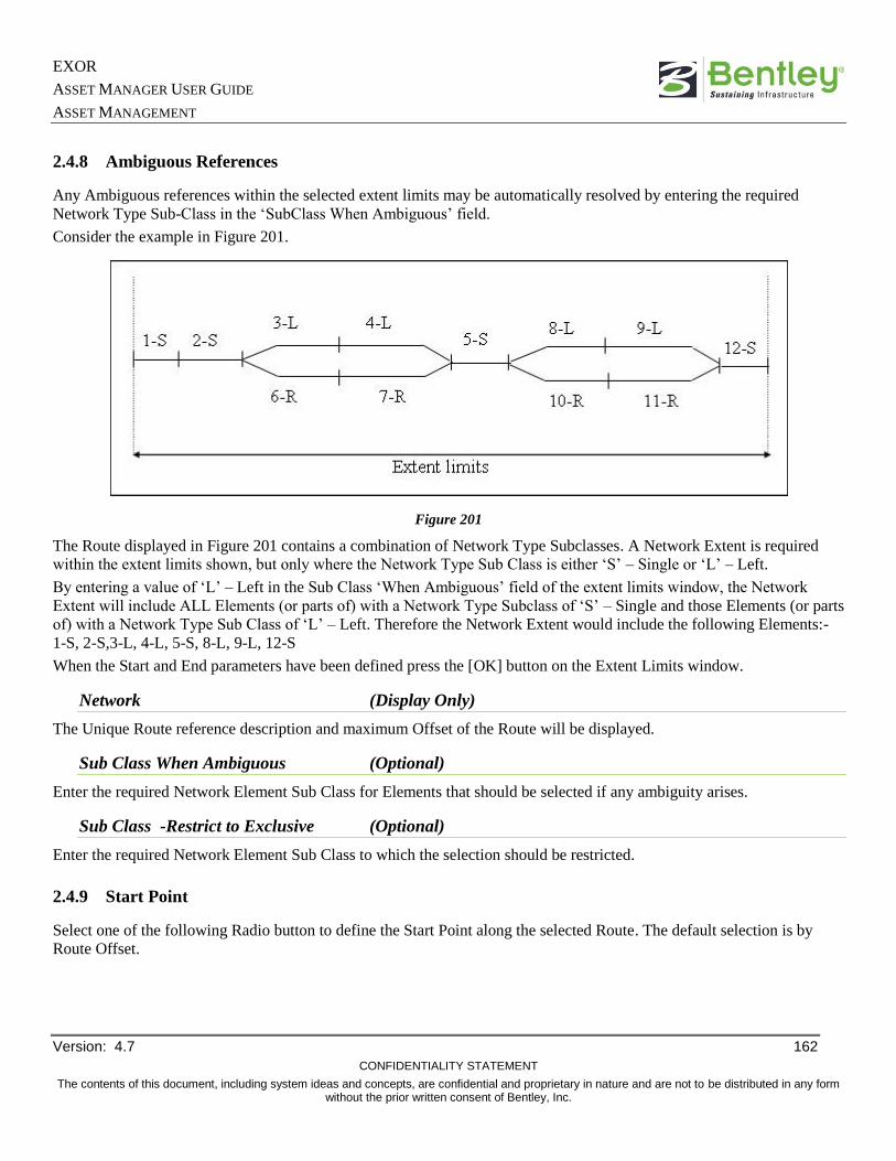
EXOR
ASSET MANAGER USER GUIDE
ASSET MANAGEMENT
Version: 4.7 162
CONFIDENTIALITY STATEMENT
The contents of this document, including system ideas and concepts, are confidential and proprietary in nature and are not to be distributed in any form without the prior written consent of Bentley, Inc.
2.4.8 Ambiguous References
Any Ambiguous references within the selected extent limits may be automatically resolved by entering the required
Network Type Sub-Class in the ‘SubClass When Ambiguous’ field.
Consider the example in Figure 201.
Figure 201
The Route displayed in Figure 201 contains a combination of Network Type Subclasses. A Network Extent is required
within the extent limits shown, but only where the Network Type Sub Class is either ‘S’ – Single or ‘L’ – Left.
By entering a value of ‘L’ – Left in the Sub Class ‘When Ambiguous’ field of the extent limits window, the Network
Extent will include ALL Elements (or parts of) with a Network Type Subclass of ‘S’ – Single and those Elements (or parts
of) with a Network Type Sub Class of ‘L’ – Left. Therefore the Network Extent would include the following Elements:-
1-S, 2-S,3-L, 4-L, 5-S, 8-L, 9-L, 12-S
When the Start and End parameters have been defined press the [OK] button on the Extent Limits window.
Network (Display Only)
The Unique Route reference description and maximum Offset of the Route will be displayed.
Sub Class When Ambiguous (Optional)
Enter the required Network Element Sub Class for Elements that should be selected if any ambiguity arises.
Sub Class -Restrict to Exclusive (Optional)
Enter the required Network Element Sub Class to which the selection should be restricted.
2.4.9 Start Point
Select one of the following Radio button to define the Start Point along the selected Route. The default selection is by
Route Offset.

EXOR
ASSET MANAGER USER GUIDE
ASSET MANAGEMENT
Version: 4.7 163
CONFIDENTIALITY STATEMENT
The contents of this document, including system ideas and concepts, are confidential and proprietary in nature and are not to be distributed in any form without the prior written consent of Bentley, Inc.
Route Offset
Enter the Route Offset for the Start Point. This should be entered in the unit of measurement defined for the selected
Group or Network Type. The defined Unit will be displayed adjacent to the Route Offset measure.
Intersection (List)
Enter the Node point of the Intersection for the Start Point. The list of values will display all the Intersection Node details
for the selected Route.
Section Offset (List)
Enter the Unique Element reference for the Start Point. The Element description will be displayed in the adjacent field.
The list of values will display all the Network Element within the selected Route.
Enter the Element Offset in the unit of measurement defined for the Datum Element in Network Types–NM0002. The
measured length of the Element will be displayed in the adjacent field.
2.4.10 End Point
Select one of the following Radio button to define the Start Point along the selected Route. The default selection is by
Route Offset
Route Offset
Enter the Route Offset for the End Point. This should be entered in the unit of measurement defined for the selected
Group or Network Type. The defined Unit will be displayed adjacent to the Route Offset measure.
Intersection (List)
Enter the Node point of the Intersection for the End Point. The list of values will display all the Intersection Node details
for the selected Route.
Section Offset (List)
Enter the Unique Element reference for the End Point. The Element description will be displayed in the adjacent field.
The list of values will display all the Network Element within the selected Route.
Enter the Element Offset in the unit of measurement defined for the Datum Element in Network Types–NM0002. The
measured length of the Element will be displayed in the adjacent field.

EXOR
ASSET MANAGER USER GUIDE
ASSET MANAGEMENT
Version: 4.7 164
CONFIDENTIALITY STATEMENT
The contents of this document, including system ideas and concepts, are confidential and proprietary in nature and are not to be distributed in any form without the prior written consent of Bentley, Inc.
2.4.11 Point Items Filter
Figure 202
A point Items Filter may be set to include or exclude point Events which are located coincident with a Network Node
point on the selected Group or Route, but which has actually been located on an adjacent Route. If the Point Item Filter is
'Open' then all Point Items located on the selected Route extent or located on connected Routes, but coincident with the
connecting Node point will be included in the Gazetteer query. If the Point Item Filter is 'Closed' only Point Items that are
specifically located on the selected Route (within the selected Route extent) will be included.
Consider an example.
Figure 203 shows a Route (9999) that has 2 intersecting Routes, namely 9991 and 9992. Two Point Items are located on
Route 9999, namely P1 and P3. Items P2 and P4 are located on Routes 9991and 9992 respectively but are coincident with
the Network Node Points which provide the connectivity with Route 9999, i.e., Item P4 is located on Route 9992 at an
Offset of 0.
Figure 203
If an 'Open' Filter is applied to Route 9999 all 4 point Items would be selected. However if the Filter was 'Closed' only
items P1 and P3 would be returned.
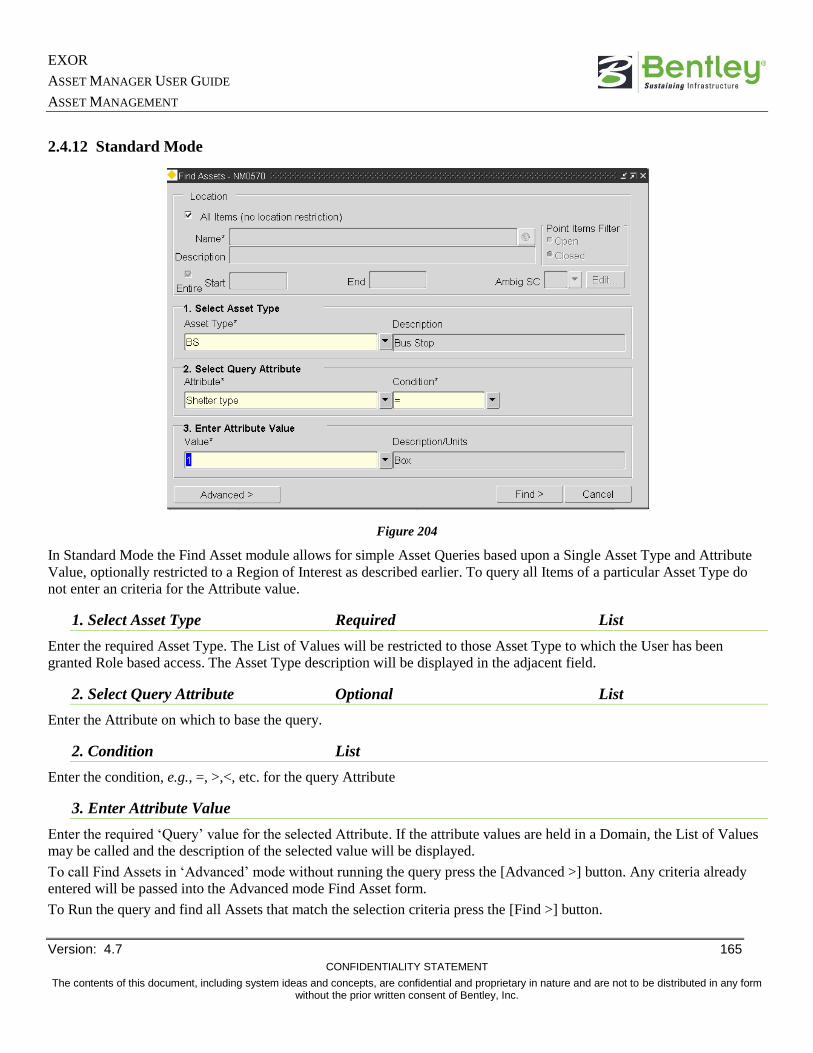
EXOR
ASSET MANAGER USER GUIDE
ASSET MANAGEMENT
Version: 4.7 165
CONFIDENTIALITY STATEMENT
The contents of this document, including system ideas and concepts, are confidential and proprietary in nature and are not to be distributed in any form without the prior written consent of Bentley, Inc.
2.4.12 Standard Mode
Figure 204
In Standard Mode the Find Asset module allows for simple Asset Queries based upon a Single Asset Type and Attribute
Value, optionally restricted to a Region of Interest as described earlier. To query all Items of a particular Asset Type do
not enter an criteria for the Attribute value.
1. Select Asset Type Required List
Enter the required Asset Type. The List of Values will be restricted to those Asset Type to which the User has been
granted Role based access. The Asset Type description will be displayed in the adjacent field.
2. Select Query Attribute Optional List
Enter the Attribute on which to base the query.
2. Condition List
Enter the condition, e.g., =, >,<, etc. for the query Attribute
3. Enter Attribute Value
Enter the required ‘Query’ value for the selected Attribute. If the attribute values are held in a Domain, the List of Values
may be called and the description of the selected value will be displayed.
To call Find Assets in ‘Advanced’ mode without running the query press the [Advanced >] button. Any criteria already
entered will be passed into the Advanced mode Find Asset form.
To Run the query and find all Assets that match the selection criteria press the [Find >] button.

EXOR
ASSET MANAGER USER GUIDE
ASSET MANAGEMENT
Version: 4.7 166
CONFIDENTIALITY STATEMENT
The contents of this document, including system ideas and concepts, are confidential and proprietary in nature and are not to be distributed in any form without the prior written consent of Bentley, Inc.
2.4.13 Advanced Mode
Figure 205
The Item Types panel is used to specify the Item Type, e.g., SIGN, to be used in the Find Assets query. To view all Items
of a particular Type do not enter any criteria for the Item Type Attributes.
Item Type (Required) List
Select the required Item Type for the query. The list of values will contain a list of Asset Types to which the user has Role
based access. The Item Type description will be displayed in the adjacent field.
To add another Asset Type press the [Create Record] button on the menu toolbar.
Note: If the query is to be restricted by XSP or Admin Unit, the required XSP or Admin Unit value may be added in the
Attribute Panel.

EXOR
ASSET MANAGER USER GUIDE
ASSET MANAGEMENT
Version: 4.7 167
CONFIDENTIALITY STATEMENT
The contents of this document, including system ideas and concepts, are confidential and proprietary in nature and are not to be distributed in any form without the prior written consent of Bentley, Inc.
2.4.14 Attributes Panel
Figure 206
The Attributes panel is used to define the Attributes of the selected Item Type to be used in the filter. If multiple
Attributes are selected the relationship between the Attributes may be defined as an 'AND' or 'OR' relationship. Attribute
criteria may also be nested with 5 levels of nesting available if required by using the Pre and Post brackets as required.
Seq (Required)
Enter the sequence number for the Attribute. Attributes values are resolved in the defined sequence order.
Operator (Required) List
Select the required Boolean connector.
Note: The Operator or the Sequence 1 Attribute must always be 'AND'.
Bracket List
If required select the appropriate Pre Bracket.
Attribute (Required) List
Select the Attribute of the selected Item to be used in the Gazetteer Filter.
Condition (Required) List
Enter the condition for the selected attribute. These are standard Oracle conditions and are set up and maintained using
Domains–HIG9120 and updating the PBI_CONDITION option.
Bracket List
If required select the appropriate Post Bracket.

EXOR
ASSET MANAGER USER GUIDE
ASSET MANAGEMENT
Version: 4.7 168
CONFIDENTIALITY STATEMENT
The contents of this document, including system ideas and concepts, are confidential and proprietary in nature and are not to be distributed in any form without the prior written consent of Bentley, Inc.
2.4.15 Values Panel
Figure 207 - Values
This panel is used to define the parameter values for the currently selected Attribute.
Value (Required) (List)
Enter the required ‘Query’ value for the currently selected Attribute. If the attribute values are held in a Domain, the List
of Values may be called and the description of the selected value will be displayed. If the ‘Condition’ entered for the
Attribute is ‘BETWEEN’ enter the second value in the field below. If a List of Values is called the extended LOV
window will be called as shown in Figure 208.

EXOR
ASSET MANAGER USER GUIDE
ASSET MANAGEMENT
Version: 4.7 169
CONFIDENTIALITY STATEMENT
The contents of this document, including system ideas and concepts, are confidential and proprietary in nature and are not to be distributed in any form without the prior written consent of Bentley, Inc.
Figure 208
This list will display the Domain Lookup Values and Descriptions associated with the selected Attribute.
The Display of the available Values may be ordered by the Lookup Value or by the Description by pressing the [Value]
button or the [Meaning] button respectively.
This will also determine which field (Value or Description) will be used when refining the search criteria to limit the
Values displayed. For example, to search for all lookup values that begin with ‘01’, press the [Value] button then enter
01% in the ‘Find’ field and press the [Find] button on the Values LOV window.
Click on the required Lookup Value to select, and press the [Select Values] button on the Values form. To close the
window without selecting a Value press the [Cancel] button.
To exit the Find Assets window and return to the Asset Item window without executing the query press the [Cancel]
button otherwise press [Next >] to view the list of Assets which met the selection criteria. The available Assets are
displayed in the Matching Items window.

EXOR
ASSET MANAGER USER GUIDE
ASSET MANAGEMENT
Version: 4.7 170
CONFIDENTIALITY STATEMENT
The contents of this document, including system ideas and concepts, are confidential and proprietary in nature and are not to be distributed in any form without the prior written consent of Bentley, Inc.
2.4.16 Matching Items
Figure 209
The Matching Items window displays the details of the Assets that met the selection criteria defined in the Find Assets
window.
The Asset Type and Asset Type description are displayed along with the Item Attributes. These attribute include the User
definable flexible attributes along with the following 'fixed' attributes:
XSP
Admin Unit
Description
Start Date
The Asset location is displayed in the Location Panel as shown in Figure 211.
This window is displayed in READONLY mode therefore attribute values may not be updated. If however an Items
attributes are to be updated, the currently selected Asset or Reference Item may 'expanded' to call the Asset Items–
NM0510 module where the attribute details, location, etc may be amended so long as the User has the required Role based
access to that module, by pressing the [Expand] button on the menu toolbar.
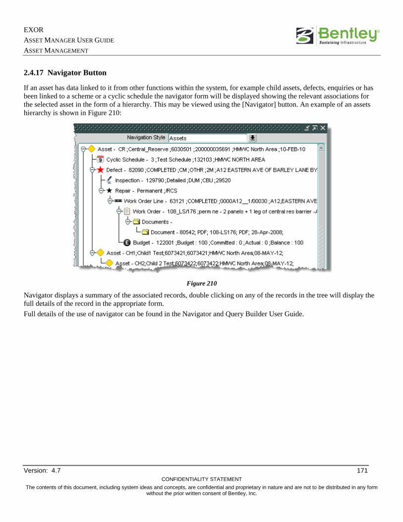
EXOR
ASSET MANAGER USER GUIDE
ASSET MANAGEMENT
Version: 4.7 171
CONFIDENTIALITY STATEMENT
The contents of this document, including system ideas and concepts, are confidential and proprietary in nature and are not to be distributed in any form without the prior written consent of Bentley, Inc.
2.4.17 Navigator Button
If an asset has data linked to it from other functions within the system, for example child assets, defects, enquiries or has
been linked to a scheme or a cyclic schedule the navigator form will be displayed showing the relevant associations for
the selected asset in the form of a hierarchy. This may be viewed using the [Navigator] button. An example of an assets
hierarchy is shown in Figure 210:
Figure 210
Navigator displays a summary of the associated records, double clicking on any of the records in the tree will display the
full details of the record in the appropriate form.
Full details of the use of navigator can be found in the Navigator and Query Builder User Guide.

EXOR
ASSET MANAGER USER GUIDE
ASSET MANAGEMENT
Version: 4.7 172
CONFIDENTIALITY STATEMENT
The contents of this document, including system ideas and concepts, are confidential and proprietary in nature and are not to be distributed in any form without the prior written consent of Bentley, Inc.
2.4.18 Location Panel
Figure 211
The Route, Datum and Groups Tabs in the Locations panel are used to display the location(s) of an Asset Item on a
Network relative to the Route(s) (linear Groups), member Datum Elements and Groups (non linear) on which it is located.
The Network Type, Group Type, Group Description and Unit of Measurement are displayed for the currently selected
record. in the 'Route' tab. The Unit of Measurement displayed will be in accordance with the Unit defined for the Group
Type or Datum Network on which the Item is located.
Figure 212
The Attribute Details of a Route, Datum or Group may be displayed by selecting the required Network record and
clicking the Right mouse button. This will display a [Details] button as shown in Figure 212. Pressing this button will
display the Attributes for the selected Network record as shown in Figure 213. The Attribute values are displayed in Read-
only mode.

EXOR
ASSET MANAGER USER GUIDE
ASSET MANAGEMENT
Version: 4.7 173
CONFIDENTIALITY STATEMENT
The contents of this document, including system ideas and concepts, are confidential and proprietary in nature and are not to be distributed in any form without the prior written consent of Bentley, Inc.
Figure 213
The display of an Items location(s) may be restricted to a specific LRM (linear Referencing Method) by setting the
Preferred LRM to the appropriate Group Type. This is done within the User Preferences form (refer to the General User
Guide). If an Item is not located on a Route of the specified Type, then the Items location will be displayed relative to
ALL LRMS on which it has a location.

EXOR
ASSET MANAGER USER GUIDE
ASSET MANAGEMENT
Version: 4.7 174
CONFIDENTIALITY STATEMENT
The contents of this document, including system ideas and concepts, are confidential and proprietary in nature and are not to be distributed in any form without the prior written consent of Bentley, Inc.
2.5 Global Asset Update – NM0530
Figure 214 - Global Asset Update
The Global Asset Update – NM0530 module is used to amend existing Asset Attribute values over a selected Region of
Interest, which may include a Group of Elements, a saved Network Extent or an individual Network Element.
If any of the Asset Items to be updated are only partially contained within the selected ‘Region of Interest’ a dialogue will
be displayed as shown here:
Figure 215
To update ONLY those ‘qualifying’ Items which are wholly located within the selected ‘Region of Interest’ select the
‘Ignore such items’ radio button, or select the ‘Update whole item’ radio button to update ALL ‘qualifying’ Items, either
wholly or partially contained within the selected ‘Region of Interest’.
When an attribute value is amended using Global Asset Update no history is kept of the ‘Old’ value. If more than 1
Attribute is entered, the Attribute Values become dependent on each other’s existence in order for the New Attribute
values to be added. For example, if an Asset Type of PAOR – Pavement Original was selected and Attributes of ‘Base
Material’ with a value of 3–Crushed Rock and ‘Formation Year’ with a value of 1968 where entered as the ‘Old’ values,
only those Asset Items of Type PAOR, within the selected Region of Interest, which currently had BOTH of these
Attribute Values would be updated.
EXOR
ASSET MANAGER USER GUIDE
ASSET MANAGEMENT
Version: 4.7 175
CONFIDENTIALITY STATEMENT
The contents of this document, including system ideas and concepts, are confidential and proprietary in nature and are not to be distributed in any form without the prior written consent of Bentley, Inc.
The same value may be entered in the ‘New Value’ column as is entered in the ‘Old Value’ column. This is especially
useful if an update of an Attribute Value is required, but only where another Attribute is of a certain value. An example of
this would be, if the Base Material Attribute of Asset Type ‘PAOR’ – Pavement Original was to be updated, but only
where the Formation Year was 1968.
Once the required values have been entered and the [Update] button is pressed on the form, the system will display the
number of Attributes that will be updated. The Asset – NM0510 form is called and the Asset Items to be updated are
displayed. To save the updates press the [Save] button on the menu toolbar.
Note: If this form is closed without saving the changes no values will be updated.
2.5.1 Global Asset Update
When you enter this form the cursor sits in the ‘Asset Type’ filed awaiting for an Item Type to be selected.
Asset Type (Required) List
Enter the Asset Type to be updated. Pressing the ‘Drop Down List’ icon adjacent to the field will display a List of
Allowable values.
Region of Interest (Required) List
Enter the Region of Interest in which Items of the selected Asset Type must be located in order to be ‘updated’. Pressing
the ‘Drop Down List’ icon adjacent to the field will call the Gazetteer from where the required Region of Interest may be
selected. The Region of Interest will default to that set in the User Preferences module if previously defined.
Attribute (Required) List
Select the required Attribute to be updated. The List of allowable values will be limited to Attributes of the selected Asset
Type.
Old Value (Required) (List)
Enter the ‘existing’ value of the Attribute that is to be updated. If the Attribute value is validated against an Asset Domain,
a List of allowable Values may be called by pressing the ‘Drop Down List’ icon adjacent to the field. A description will
be displayed in the adjacent field for such Attributes.
New Value (Required) (List)
Enter the ‘new’ value for the Attribute of the ‘qualifying’ Asset Items. If the Attribute value is validated against an Asset
Domain, a List of allowable Values may be called by pressing the ‘Drop Down List’ icon adjacent to the field. A
description will be displayed in the adjacent field for such Attributes.
Mandatory (Display Only)
If the selected Asset Attribute has been defined as Mandatory in the Asset Metamodel – NM0410 form, this checkbox will
be selected.
To Update the ‘qualifying’ Attribute values press the [Update] button on the form. The number of ‘qualifying’ Items will
be displayed in a Dialogue window. Press [OK] to continue.
If Cross Attribute Validation Rules has been defined for an Attribute using Cross Attribute Validation Set-up – NM0550
and the data entered is invalid the appropriate Error message will be displayed, an example of which is displayed below.

EXOR
ASSET MANAGER USER GUIDE
ASSET MANAGEMENT
Version: 4.7 176
CONFIDENTIALITY STATEMENT
The contents of this document, including system ideas and concepts, are confidential and proprietary in nature and are not to be distributed in any form without the prior written consent of Bentley, Inc.
Figure 216
The Asset – NM0510 form is called and the Asset Items to be updated are displayed. To save the updates press the [Save]
button on the menu toolbar.
Note: If this form is closed without saving the changes no values will be updated.

EXOR
ASSET MANAGER USER GUIDE
ASSET MANAGEMENT
Version: 4.7 177
CONFIDENTIALITY STATEMENT
The contents of this document, including system ideas and concepts, are confidential and proprietary in nature and are not to be distributed in any form without the prior written consent of Bentley, Inc.
2.6 Delete Global Assets – NM0575
Figure 217
Occasionally the Asset manager may want to end-date or even delete totally, large quantities of Asset Data in a single
transaction. This may be as a result of erroneously entered data or end-date existing data before a new Asset survey is
conducted over a section of the Network. End dating (retaining history) or deleting (no history retained) existing Asset
data before a new inspection, ensures that no duplicate items exist for any location.
The Delete Global Assets – NM0575 module allows Assets of Multiple Types and XSP’s to be either end dated or entirely
deleted. A network filter may be imposed to restrict the end-date/deletion to only those assets located either wholly or
partially within the selected region of interest. All Assets of a certain type may be end-dated/deleted by checking the ‘All
items – no location Restriction’) option.
Figure 218

EXOR
ASSET MANAGER USER GUIDE
ASSET MANAGEMENT
Version: 4.7 178
CONFIDENTIALITY STATEMENT
The contents of this document, including system ideas and concepts, are confidential and proprietary in nature and are not to be distributed in any form without the prior written consent of Bentley, Inc.
2.6.1 Delete Global Assets
Figure 219
Delete Global Assets is a wizard style module that guides the User through the various stages of either deleting or end-
dating the required Asset items. The first stage allows a Network Restriction to be imposed.
2.6.2 Step 1–Network Restriction
Figure 220
The Network Restriction tab allows a region of Interest to be selected in order to restrict the end-date/deletion of Assets to
those, that are either wholly or partially located within the selected network region. If a Datum element or linear group is
selected the extent may be further restricted by entering the required Start and End Offsets.

EXOR
ASSET MANAGER USER GUIDE
ASSET MANAGEMENT
Version: 4.7 179
CONFIDENTIALITY STATEMENT
The contents of this document, including system ideas and concepts, are confidential and proprietary in nature and are not to be distributed in any form without the prior written consent of Bentley, Inc.
If no Network Restriction is required, select the ‘All Items (no location restriction) checkbox. All items of the selected
Types will be processed irrespective of location.
All Items (Checkbox)
If this option is selected the end-date/deletion will be based purely on the selected Asset Types and XSP’s and not further
restricted by the location of an Asset. If the option is selected the remaining fields within the Location Panel will be
disabled.
Name
Enter the required Region Of Interest or select from the Gazetteer (refer the Network Manager User guide).
Description
The description of the selected Region of Interest will be displayed.
If a Datum Element or Linear Group has been selected a filter may be applied so as to include only those Items which
meet the defined selection criteria and are located within the extent of Network between specified Start and End Offsets
on the Route. The default option is to return the entire Route or Linear Group. To restrict the end-date/deletion to an
extent of Network between specified Start and End Offsets, uncheck the 'Entire' check box and add the required start and
end Offsets as required in the 'Start' and 'End' fields respectively.
Entire (Checkbox)
Uncheck this if the Datum or Route is to be restricted by Start and End Offsets. This option is only available if a Datum
Element or Linear Group is selected.
Start
If the 'Entire' checkbox is unselected, enter the required Start Offset. The default value is the minimum Offset of the
selected Route.
End
If the 'Entire' checkbox is unselected, enter the required End Offset. The default value is the maximum Offset of the
selected Route.
The Unit of measurement displayed will be determined by the select region of interest.
Ambig SC (Ambiguous Subclass)
Any Ambiguous references within the selected extent limits may be automatically resolved by entering the required
Network Type Sub-Class in the ‘Ambig SC’ field.
Consider the example in Figure 221.

EXOR
ASSET MANAGER USER GUIDE
ASSET MANAGEMENT
Version: 4.7 180
CONFIDENTIALITY STATEMENT
The contents of this document, including system ideas and concepts, are confidential and proprietary in nature and are not to be distributed in any form without the prior written consent of Bentley, Inc.
Figure 221
The Route displayed above contains a combination of Network Type Subclasses. A query is required within the extent
limits shown, but only where the Network Type Sub Class is either ‘S’ – Single or ‘L’ – Left.
By entering a value of ‘L’ – left in the 'Ambig SC' field, the query will include ALL Elements (or parts of) with a
Network Type Subclass of ‘S’ – Single and those Elements (or parts of) with a Network Type Sub Class of ‘L’ – Left.
Therefore the query would include the following Elements:- 1-S, 2-S, 3-L, 4-L, 5-S, 8-L, 9-L, 12-S
Note: If Sub Class is not used as a carriageway identifier, this functionality may be switched off by setting Product
Option DISAMBIGSC to ‘N’.

EXOR
ASSET MANAGER USER GUIDE
ASSET MANAGEMENT
Version: 4.7 181
CONFIDENTIALITY STATEMENT
The contents of this document, including system ideas and concepts, are confidential and proprietary in nature and are not to be distributed in any form without the prior written consent of Bentley, Inc.
2.6.3 Step 2 – Asset Categories
Figure 222
This tab allows the Asset Categories and XSP’s for the Asset Types to be end-dated/deleted to be selected. Using Asset
Categories provides a quick and easy method of selecting all Condition Data assets for example. Only Assets of the
selected Categories will be processed when end-dating/deleting.
The following Asset categories are excluded from the Category selection.
$ Valuations
F Foreign Table/External Assets
G Additional Data
R Road Construction
X Generated Exclusive Asset Types
The Categories of the Assets that are to be end-dated /deleted should be selected for inclusion in the processing.
When an Asset Category is selected all valid XSP’s for Assets Types of that category will be displayed in the XSP panel.
This allows the end-date/deletion routine to be filtered to include only Assets located on the selected XSP’s.
The XSP’s are ordered by the most commonly used XSP within Asset Types.
If no XSP’s are selected all Assets items of the selected Types will be processed.
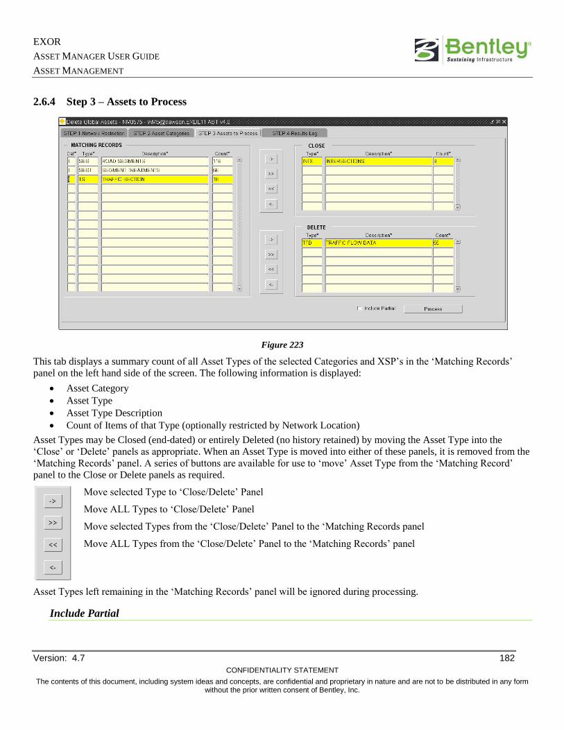
EXOR
ASSET MANAGER USER GUIDE
ASSET MANAGEMENT
Version: 4.7 182
CONFIDENTIALITY STATEMENT
The contents of this document, including system ideas and concepts, are confidential and proprietary in nature and are not to be distributed in any form without the prior written consent of Bentley, Inc.
2.6.4 Step 3 – Assets to Process
Figure 223
This tab displays a summary count of all Asset Types of the selected Categories and XSP’s in the ‘Matching Records’
panel on the left hand side of the screen. The following information is displayed:
Asset Category
Asset Type
Asset Type Description
Count of Items of that Type (optionally restricted by Network Location)
Asset Types may be Closed (end-dated) or entirely Deleted (no history retained) by moving the Asset Type into the
‘Close’ or ‘Delete’ panels as appropriate. When an Asset Type is moved into either of these panels, it is removed from the
‘Matching Records’ panel. A series of buttons are available for use to ‘move’ Asset Type from the ‘Matching Record’
panel to the Close or Delete panels as required.
Move selected Type to ‘Close/Delete’ Panel
Move ALL Types to ‘Close/Delete’ Panel
Move selected Types from the ‘Close/Delete’ Panel to the ‘Matching Records panel
Move ALL Types from the ‘Close/Delete’ Panel to the ‘Matching Records’ panel
Asset Types left remaining in the ‘Matching Records’ panel will be ignored during processing.
Include Partial
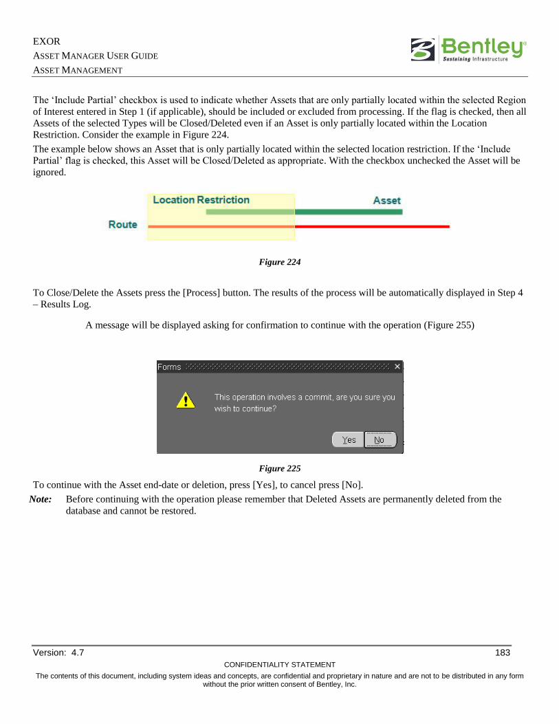
EXOR
ASSET MANAGER USER GUIDE
ASSET MANAGEMENT
Version: 4.7 183
CONFIDENTIALITY STATEMENT
The contents of this document, including system ideas and concepts, are confidential and proprietary in nature and are not to be distributed in any form without the prior written consent of Bentley, Inc.
The ‘Include Partial’ checkbox is used to indicate whether Assets that are only partially located within the selected Region
of Interest entered in Step 1 (if applicable), should be included or excluded from processing. If the flag is checked, then all
Assets of the selected Types will be Closed/Deleted even if an Asset is only partially located within the Location
Restriction. Consider the example in Figure 224.
The example below shows an Asset that is only partially located within the selected location restriction. If the ‘Include
Partial’ flag is checked, this Asset will be Closed/Deleted as appropriate. With the checkbox unchecked the Asset will be
ignored.
Figure 224
To Close/Delete the Assets press the [Process] button. The results of the process will be automatically displayed in Step 4
– Results Log.
A message will be displayed asking for confirmation to continue with the operation (Figure 255)
Figure 225
To continue with the Asset end-date or deletion, press [Yes], to cancel press [No].
Note: Before continuing with the operation please remember that Deleted Assets are permanently deleted from the
database and cannot be restored.
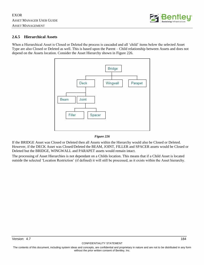
EXOR
ASSET MANAGER USER GUIDE
ASSET MANAGEMENT
Version: 4.7 184
CONFIDENTIALITY STATEMENT
The contents of this document, including system ideas and concepts, are confidential and proprietary in nature and are not to be distributed in any form without the prior written consent of Bentley, Inc.
2.6.5 Hierarchical Assets
When a Hierarchical Asset is Closed or Deleted the process is cascaded and all ‘child’ items below the selected Asset
Type are also Closed or Deleted as well. This is based upon the Parent – Child relationship between Assets and does not
depend on the Assets location. Consider the Asset Hierarchy shown in Figure 226.
Figure 226
If the BRIDGE Asset was Closed or Deleted then all Assets within the Hierarchy would also be Closed or Deleted.
However, if the DECK Asset was Closed/Deleted the BEAM, JOINT, FILLER and SPACER assets would be Closed or
Deleted but the BRIDGE, WINGWALL and PARAPET assets would remain intact.
The processing of Asset Hierarchies is not dependant on a Childs location. This means that if a Child Asset is located
outside the selected ‘Location Restriction’ (if defined) it will still be processed, as it exists within the Asset hierarchy.

EXOR
ASSET MANAGER USER GUIDE
ASSET MANAGEMENT
Version: 4.7 185
CONFIDENTIALITY STATEMENT
The contents of this document, including system ideas and concepts, are confidential and proprietary in nature and are not to be distributed in any form without the prior written consent of Bentley, Inc.
2.6.6 Step 4 –Results Log
Figure 227
This tab displays a result log for each of the Assets processed and displays any errors that may have occurred. The
following information is displayed:
Asset Type
Action (C- Closed, D – Deleted)
Asset internal Id (IIT_NE_ID)
Asset Primary key
Asset Description
Message – indicates if the Asset has been processed correctly
The display of results can be toggled between showing errors only and Showing all results by pressing the [Error Only]
and [All] buttons respectively.

EXOR
ASSET MANAGER USER GUIDE
ASSET MANAGEMENT
Version: 4.7 186
CONFIDENTIALITY STATEMENT
The contents of this document, including system ideas and concepts, are confidential and proprietary in nature and are not to be distributed in any form without the prior written consent of Bentley, Inc.
2.7 Asset Admin Unit Security Maintenance–NM1861
Figure 228 - Asset Admin Unit Security Maintenance Menu Option
The Asset Admin Unit Security Maintenance–NM1861 module allows the Admin Units of Asset Items to be amended to
cater for changes in Administrative Unit Area Boundaries. The Admin Units of all Asset Items associated with the
specified Admin Type within the specified Area of Interest will be set to the newly defined Admin Unit. A full history is
retained of the Admin Unit of an Item prior to the Admin Unit maintenance operation.
Note: A User must have Role and Admin Unit based access to all affected Items of Asset or be an 'Unrestricted' User to
carry out this operation.
If a continuous Asset Item spans the boundary of the specified Area of Interest the Item will be 'split' at the Boundary with
its Admin Unit and Location being assigned as appropriate. Figure 229–Figure 231 show an operational example.
Figure 229
In Figure 229 a single Continuous Item of Admin Unit REG2 is located on a Route starting at the existing Regional
Boundary. A Point Item with an Admin Unit of REG2 is also displayed.

EXOR
ASSET MANAGER USER GUIDE
ASSET MANAGEMENT
Version: 4.7 187
CONFIDENTIALITY STATEMENT
The contents of this document, including system ideas and concepts, are confidential and proprietary in nature and are not to be distributed in any form without the prior written consent of Bentley, Inc.
Figure 230 displays a proposed new Regional Boundary and the area affected by the change in Admin Units.
Figure 230
Once the Area of Interest affected by the Regional Boundary change has been identified and the Admin Unit Security
Maintenance operation has been conducted the Point Item will have an Admin Unit of REG1. The Continuous Item
originally located in Region 2 will have been 'split' and a new Item with an Admin Unit of REG1 will have been created.
The location of the original Continuous Item in Region 2 will have been updated and will start at the new Regional
Boundary.
Figure 231 displays the Asset Items after the Regional Boundary change.
Figure 231

EXOR
ASSET MANAGER USER GUIDE
ASSET MANAGEMENT
Version: 4.7 188
CONFIDENTIALITY STATEMENT
The contents of this document, including system ideas and concepts, are confidential and proprietary in nature and are not to be distributed in any form without the prior written consent of Bentley, Inc.
2.7.1 Asset Admin Unit Security Maintenance
Figure 232
Area of Interest (Required) List, Gaz
Enter the Unique of the Area of Interest over which to maintain Admin Units. Groups or Network Extents may be selected
from the Gazetteer, called by pressing the 'Drop Down List' icon adjacent to the field.
The Group or Network Extent description will be displayed in the adjacent field.
Admin Type (Required) List
Enter the Admin Type of the Items to be updated. All Asset Items with Admin Units of this Type, which are located either
wholly or partially within the selected Area of Interest, will be affected.
The Admin Type description will be displayed in the adjacent field.
Admin Unit (Required) List
Enter the new Admin Unit for Items within the selected Area of Interest.
The Admin Unit description will be displayed in the adjacent field.
Effective Date (Required, Default)
Enter the date at which the Admin Unit change becomes affective.
To Update the Admin Units of any affected Asset Items press the [Run Update] button. Once the operation is complete a
dialogue will be displayed as shown in Figure 233. Press [Yes] to save the changes or [No] to quit without saving.
Figure 233
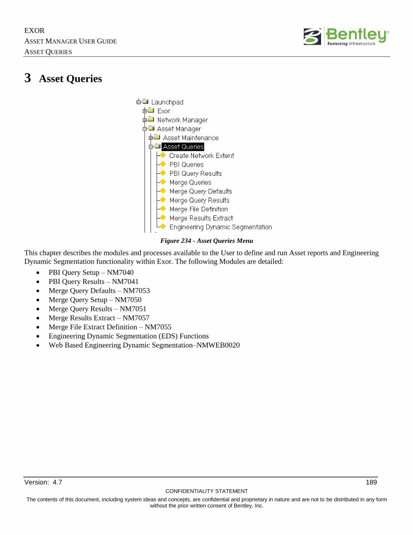
EXOR
ASSET MANAGER USER GUIDE
ASSET QUERIES
Version: 4.7 189
CONFIDENTIALITY STATEMENT
The contents of this document, including system ideas and concepts, are confidential and proprietary in nature and are not to be distributed in any form without the prior written consent of Bentley, Inc.
3 Asset Queries
Figure 234 - Asset Queries Menu
This chapter describes the modules and processes available to the User to define and run Asset reports and Engineering
Dynamic Segmentation functionality within Exor. The following Modules are detailed:
PBI Query Setup – NM7040
PBI Query Results – NM7041
Merge Query Defaults – NM7053
Merge Query Setup – NM7050
Merge Query Results – NM7051
Merge Results Extract – NM7057
Merge File Extract Definition – NM7055
Engineering Dynamic Segmentation (EDS) Functions
Web Based Engineering Dynamic Segmentation–NMWEB0020

EXOR
ASSET MANAGER USER GUIDE
ASSET QUERIES
Version: 4.7 190
CONFIDENTIALITY STATEMENT
The contents of this document, including system ideas and concepts, are confidential and proprietary in nature and are not to be distributed in any form without the prior written consent of Bentley, Inc.
3.1 PBI Query Setup – NM7040
Figure 235 - PBI Query Setup Menu Option
This module is used to define sets of Parameter Based Inquiries (PBI). A PBI query returns the Network Locations of any
data items (Datum Elements or Assets) which match the defined selection criteria, thus any Assets which are not located
on a Network will not be included in the Query. If the query is to be based upon actual Asset Items and not the locations
of the Assets Items the Find Assets–NM0570 module should be used.
A PBI query may be based purely on the existence of an Item. For example, a query may be applied to a Network Group
representing an entire Regional Area to return the Network locations where items of Guard Rail exist. This type of query
does not require any Attributes to be defined for the Item Type.
A PBI query may also be based upon a single Asset Type or a Datum Network Type or on a combination of several
different Asset Types. If more than one Item type (either Asset or Network) is used an 'AND' relationship between the
Item types will be established and the resulting Network locations returned from the PBI query will correspond to the
Network locations where ALL of the Filter query criteria are met.
Each Item Type selected for the PBI may be queried on a single Attribute and value or Multiple Attribute and value
combinations. If multiple Attributes are selected the relationship between the Attributes may be defined as an 'AND' or
'OR' relationship. Attribute criteria may also be nested with 5 levels of nesting available if required.
The results of a PBI query may be saved for future use and can be displayed spatially.
Creating a Network Extent from the results of a PBI query, which used a saved Network Extent as the Region of Interest,
is a process which allows Network Extents to, be ‘refined’ based on the Attribute value of Assets located within the
Network Extent.
Once a PBI has been defined it can be saved for reuse. The query can be executed using PBI Results–NM7041, which can
be launched using the [Run Query] button on the form or from the Exor menu.
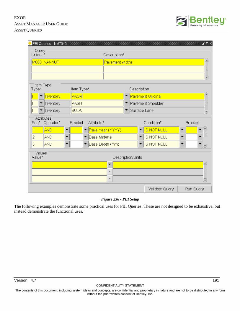
EXOR
ASSET MANAGER USER GUIDE
ASSET QUERIES
Version: 4.7 191
CONFIDENTIALITY STATEMENT
The contents of this document, including system ideas and concepts, are confidential and proprietary in nature and are not to be distributed in any form without the prior written consent of Bentley, Inc.
Figure 236 - PBI Setup
The following examples demonstrate some practical uses for PBI Queries. These are not designed to be exhaustive, but
instead demonstrate the functional uses.

EXOR
ASSET MANAGER USER GUIDE
ASSET QUERIES
Version: 4.7 192
CONFIDENTIALITY STATEMENT
The contents of this document, including system ideas and concepts, are confidential and proprietary in nature and are not to be distributed in any form without the prior written consent of Bentley, Inc.
3.1.1 Example 1–Filtering on Network Attributes
This example uses Attributes of a Base Datum Network Type (LCWY–Link Carriageway) to restrict the Network
locations to those Elements which have a Carriageway Code of 'C' (carriageway code is a flexible attribute) AND a length
of over 150.
Table 3
Type Item Type Description
E–Element LCWY Link Carriagway
Seq Operator ( Attribute Condition ) Value
1 Carriageway Code = C
2 AND Element Length > 150
3.1.2 Example 2–Filtering on Single Asset Type
This example uses Attributes of an Asset Type of 'SIGN' to return the Network locations where Signs with a Sign Post
Type of M (Metal) and the Sign Catalogue Number is C-031 (Reduce Speed) are located or where Signs with a Catalogue
number of C-029X (Prepare to Stop), irrespective of the Sign Post Type, are located.
Table 4
Type Item Type Description
I–Asset SIGN Road Signs
Seq Operator ( Attribute Condition ) Value
1 ( Sign Post Type = M
2 AND Catalogue Number = ) C-031
3 OR Catalogue Number = C-029X
3.1.3 Example 3–Filtering on Multiple Asset Types
This example uses multiple Asset Types, namely FC- Functional Class and DR–Dust Range, to return the Network
locations where the Functional Class in 'N'–Minor, and the Dust Range Warrant Type is 'S' Sign.
Table 5
Selected Group/Extent 9999–Mountain Overpass
Type Item Type Description
I–Asset FC Functional Class
Seq Operator ( Attribute Condition ) Value
1 Functional Class = N

EXOR
ASSET MANAGER USER GUIDE
ASSET QUERIES
Version: 4.7 193
CONFIDENTIALITY STATEMENT
The contents of this document, including system ideas and concepts, are confidential and proprietary in nature and are not to be distributed in any form without the prior written consent of Bentley, Inc.
Type Item Type Description
I–Asset DR Dust Range
Seq Operator ( Attribute Condition ) Value
1 Warrant Type = S
Figure 237 shows the Network location returned from the Gazetteer Filter.
Figure 237

EXOR
ASSET MANAGER USER GUIDE
ASSET QUERIES
Version: 4.7 194
CONFIDENTIALITY STATEMENT
The contents of this document, including system ideas and concepts, are confidential and proprietary in nature and are not to be distributed in any form without the prior written consent of Bentley, Inc.
Figure 238 - PBI Scenario
3.1.4 Example 4
Figure 238 above depicts Route H025 from its start to Route Offset 1.36. A Network Extent has been created (greyed
area) from SLK 0 to 0.99. The width values for Asset Type PAOR –Pavement Original are displayed on the left of the
diagram, and the Values for Asset Type CORO – Roughness on the right. For explanation purposes XSP’s have been
disregarded.
A requirement exists to perform a series of queries on the Network Extent created.
Query the Extent for all Items of Pavement Original with a Width of over 9m.
Query the Extent for all Items of Roughness with a value greater than 65.
Query to combine these and perform a query for all occurrences within the Network Extent were the Pavement
Width is over 9m wide AND the Roughness is greater than 70.

EXOR
ASSET MANAGER USER GUIDE
ASSET QUERIES
Version: 4.7 195
CONFIDENTIALITY STATEMENT
The contents of this document, including system ideas and concepts, are confidential and proprietary in nature and are not to be distributed in any form without the prior written consent of Bentley, Inc.
3.1.4.1 Query 1
Pavement Original with a Width of greater than 9m
Parameters
Region of Interest Cockburn Rd (SLK 0.99)
Asset Type PAOR Pavement Original
Attribute Width (m) Condition Greater than >
Value 9
Expected Results from PBI Query
Section Unique Begin Section Point End Section Point Measure Begin
SLK
End
SLK
H025/2-S 0 190 0 0.19
H025/3-S 0 70 190
H025/4-S 0 130 260
H025/5-S 0 50 390
H025/6-S 0 160 440
H025/7-S 0 200 600 0.99
3.1.4.2 Query 2
Roughness with a value of greater than 65
Parameters
Region of Interest Cockburn Rd (SLK 0.99)
Asset Type CORO Roughness
Attribute Value Condition Greater than >
Value 65
Expected Results from PBI Query
Section Unique Begin Section Offset End Section Offset Measure Begin
SLK
End
SLK
H025/3-S 50 70 0 0.43
H025/4-S 0 130 20
H025/5-S 0 50 150
H025/6-S 0 160 200
H025/7-S 0 200 360 0.99

EXOR
ASSET MANAGER USER GUIDE
ASSET QUERIES
Version: 4.7 196
CONFIDENTIALITY STATEMENT
The contents of this document, including system ideas and concepts, are confidential and proprietary in nature and are not to be distributed in any form without the prior written consent of Bentley, Inc.
3.1.4.3 Query 3
Pavement Width is over 9m wide AND the Roughness is greater than 60.
Parameters
Region of Interest Cockburn Rd (SLK 0.99)
Asset Type PAOR Pavement Original
Attribute Width (m) Condition Greater than >
Value 9
Asset Type CORO Roughness
Attribute Value Condition Greater than >
Value 60
Expected Results from PBI Query
Section Unique Begin Section Offset End Section Offset Measure Begin
SLK
End
SLK
H025/3-S 50 70 0 0.43
H025/4-S 0 130 20
H025/5-S 0 50 150
H025/6-S 0 160 200
H025/7-S 0 200 360 0.99

EXOR
ASSET MANAGER USER GUIDE
ASSET QUERIES
Version: 4.7 197
CONFIDENTIALITY STATEMENT
The contents of this document, including system ideas and concepts, are confidential and proprietary in nature and are not to be distributed in any form without the prior written consent of Bentley, Inc.
3.1.5 PBI Queries
Figure 239 - PBI Queries
The PBI Queries form comprises of 4 panels. These panels relate to the following information
First Panel Query Name and Description
Second Panel Asset Types
Third Panel Asset Attributes for the selected Type(s)
Fourth Panel Attribute Value for the selected Attributes
When you enter this form the cursor sits in the ‘Unique’ field in the first Panel waiting for a new PBI Query to be set-up
or existing PBI Queries to be retrieved. To query back an existing PBI Query set-up press the [Enter Query] button on the
menu toolbar (or press F7), enter some selection criteria, then press the [Execute Query] button (or press F8).

EXOR
ASSET MANAGER USER GUIDE
ASSET QUERIES
Version: 4.7 198
CONFIDENTIALITY STATEMENT
The contents of this document, including system ideas and concepts, are confidential and proprietary in nature and are not to be distributed in any form without the prior written consent of Bentley, Inc.
3.1.6 Query Panel
Figure 240 - Query Panel
Unique (Required)
Enter a Unique Reference for the PBI Query Set-up. A maximum of 30 characters is allowed.
Description (Required)
Enter a Description for the PBI Query Set-up. A maximum of 80 characters is allowed.
3.1.7 Item Type Panel
Figure 241 - Item Type Panel
The Item Types panel is used to specify the Item category (Asset or Element) and the Item Type, e.g., SIGN, to be used in
the PBI Query. If more than one Item type is specified an 'AND' relationship is established between the Types.
The PBI Query may be based purely on the existence of an Item. For example, a Query may be applied to a Network
Group representing an entire Regional Area to return the Network locations where items of Guard Rail exist. This type of
Query does not require any Attributes to be defined for the Item Type.
Note: If the query is to be restricted by XSP, the required XSP value may be added in the Attribute Panel.
Type (Required) List
Select the Item category. This will be either 'E–Element' if filtering on Datum Network Attributes or 'I–Asset' if filtering
on the Attributes of an Asset Type.
The Type description will be displayed in the adjacent field.
Item Type (Required) List
Select the required Item Type for the filter. If the Item category selected is 'E–Element' the list of values will contain a list
of Datum Network Types. If 'I–Asset' has been selected, the list of values will contain a list of Asset Types to which the
user has Role based access including any Foreign Table Asset Types. The Item Type description will be displayed in the
adjacent field.
To add another Asset Type press the [Create Record] button on the menu toolbar.

EXOR
ASSET MANAGER USER GUIDE
ASSET QUERIES
Version: 4.7 199
CONFIDENTIALITY STATEMENT
The contents of this document, including system ideas and concepts, are confidential and proprietary in nature and are not to be distributed in any form without the prior written consent of Bentley, Inc.
3.1.8 Attributes Panel
Figure 242 - Attributes
The Attributes panel is used to define the Attributes of the selected Item Type to be used in the PBI Query. If multiple
Attributes are selected the relationship between the Attributes may be defined as an 'AND' or 'OR' relationship. Attribute
criteria may also be nested with 5 levels of nesting available if required by using the Pre and Post brackets as required.
Seq (Required)
Enter the sequence number for the Attribute. Attributes values are resolved in the defined sequence order.
Operator (Required) List
Select the required Boolean connector.
Note: The Operator or the Sequence 1 Attribute must always be 'AND'.
Bracket List
If required select the appropriate Pre Bracket.
Attribute (Required) List
Select the Attribute of the selected Item to be used in the Gazetteer Filter.
Condition (Required) List
Enter the condition for the selected attribute. These are standard Oracle conditions and are set up and maintained using
Domains–HIG9120 and updating the PBI_CONDITION option.
Bracket List
If required select the appropriate Post Bracket.

EXOR
ASSET MANAGER USER GUIDE
ASSET QUERIES
Version: 4.7 200
CONFIDENTIALITY STATEMENT
The contents of this document, including system ideas and concepts, are confidential and proprietary in nature and are not to be distributed in any form without the prior written consent of Bentley, Inc.
3.1.9 Values Panel
Figure 243 - Values
This panel is used to define the parameter values for the currently selected Attribute. For example, if Asset Type PAOR –
Pavement Original was being used to Filter all Network locations with Width value of greater than 9m, a value of ‘9’
would be entered.
Value (Required) (List)
Enter the required ‘Query’ value for the currently selected Attribute. If the attribute values are held in a Domain, the List
of Values may be called and the description of the selected value will be displayed. If the ‘Condition’ entered for the
Attribute is ‘BETWEEN’ enter the second value in the field below.
If a List of Values is called the extended LOV window will be called as shown in Figure 244.
.

EXOR
ASSET MANAGER USER GUIDE
ASSET QUERIES
Version: 4.7 201
CONFIDENTIALITY STATEMENT
The contents of this document, including system ideas and concepts, are confidential and proprietary in nature and are not to be distributed in any form without the prior written consent of Bentley, Inc.
Figure 244
This list will display the Domain Lookup Values and Descriptions associated with the selected Attribute.
The Display of the available Values may be ordered by the Lookup Value or by the Description by pressing the [Value]
button or the [Meaning] button respectively.
This will also determine which field (Value or Description) will be used when refining the search criteria to limit the
Values displayed. For example, to search for all lookup values that begin with ‘01’, press the [Value] button then enter
01% in the ‘Find’ field and press the [Find] button on the Values LOV window.
Click on the required Lookup Value to select, and press the [Select Values] button on the Values form. To close the
window without selecting a Value press the [Cancel] button.
Before the Query is used it should be checked to ensure that the parameters entered are valid. This can be done by
pressing the [Validate Query] button on the form. A message will be displayed (Figure 245) if the Query is valid. If the
Query is Invalid an appropriate message will be displayed (Figure 246), allowing the User to correct the Query
Parameters.

EXOR
ASSET MANAGER USER GUIDE
ASSET QUERIES
Version: 4.7 202
CONFIDENTIALITY STATEMENT
The contents of this document, including system ideas and concepts, are confidential and proprietary in nature and are not to be distributed in any form without the prior written consent of Bentley, Inc.
Figure 245 - Valid Query
Figure 246 - Invalid Query
To execute the query ensure that it is first saved by pressing the [Save] button on the menu toolbar, then press the [Run
Query] button on the form. This will call PBI Query Results–NM7041 and allow a Region Of Interest to be selected.
3.1.10 PBI Toolbar
Figure 247
The PBI Floating Toolbar may be toggled on/off by pressing the [Toolbar] button on the menu toolbar. The following
buttons are available:
AR Sets the currently selected PBI query as the User default PBI for use with Assets on Route –
NM0560
AS Create Attribute Set

EXOR
ASSET MANAGER USER GUIDE
ASSET QUERIES
Version: 4.7 203
CONFIDENTIALITY STATEMENT
The contents of this document, including system ideas and concepts, are confidential and proprietary in nature and are not to be distributed in any form without the prior written consent of Bentley, Inc.
3.1.11 Create New Attribute Set
Figure 248
A new Attribute Set can be created from the Items and Attributes used when defining a PBI Query. The Attribute Set can
be subsequently used in modules such as Assets on a Route and in some Reports to restrict the displayed Attributes and
values. the new Attribute Set may be set as the Default Set by selecting the 'Set as Default' check box. To create the new
Attribute Set press the [Create] button or [Cancel] to return to the PBI Query Setup.

EXOR
ASSET MANAGER USER GUIDE
ASSET QUERIES
Version: 4.7 204
CONFIDENTIALITY STATEMENT
The contents of this document, including system ideas and concepts, are confidential and proprietary in nature and are not to be distributed in any form without the prior written consent of Bentley, Inc.
3.2 PBI Query Results – NM7041
Figure 249 - PBI Query Results Menu Option
This module is used to select a Region of Interest to Query and to view the Query Results that may be displayed by the
User Preferred LRM (defined using the User Preferences–HIG1840 module). PBI Query parameters will have already
been defined using PBI Query Set-up–NM7040
A Region of Interest is selected via the Gazetteer, allowing the selection of a Network Group or a saved Network Extent.
If the required Region of Interest does not already exist as a Network Group or Network Extent, the Gazetteer can be used
to launch Create Network Extents–NM0120, allowing the User to define the required Region of Interest.
The Results from a PBI Query may be saved and viewed via the ‘PBI Jobs’ window.

EXOR
ASSET MANAGER USER GUIDE
ASSET QUERIES
Version: 4.7 205
CONFIDENTIALITY STATEMENT
The contents of this document, including system ideas and concepts, are confidential and proprietary in nature and are not to be distributed in any form without the prior written consent of Bentley, Inc.
Figure 250 - PBI Query Results
3.2.1 Displaying PBI Query Results by User Preferred LRM
The results of a PBI Query may be displayed relative to any of the LRM's (Linear Referencing Methods) defined within
the Exor Network Model. The preferred LRM is set using the User Preferences–HIG1840 module (see the General User
Guide for more details) as shown in Figure 251 which may be called by pressing the Calendar Button on the Highways
Menu Toolbar as shown in Figure 252.

EXOR
ASSET MANAGER USER GUIDE
ASSET QUERIES
Version: 4.7 206
CONFIDENTIALITY STATEMENT
The contents of this document, including system ideas and concepts, are confidential and proprietary in nature and are not to be distributed in any form without the prior written consent of Bentley, Inc.
Figure 251
Figure 252
To display the PBI Result set in a different LRM reset the Preferred LRM value within the User Preferences module.
Note: The PBI Query DOES NOT have to be re-run.
If no LRM is selected, i.e., the Preferred LRM value is set to ALL LRMS; the PBI Results will be displayed relative to the
Datum Network Elements.
3.2.2 PBI Query Results
Figure 253
When you enter this form the cursor sits in the ‘Query’ field waiting for a PBI Query to be selected. If the form has been
called from within PBI Query Set-up–NM7040, the selected Query will be automatically displayed.
Query (Required) (List)
Enter the PBI Query name to be run. The PBI Query description will be displayed in the field beneath the Query name.
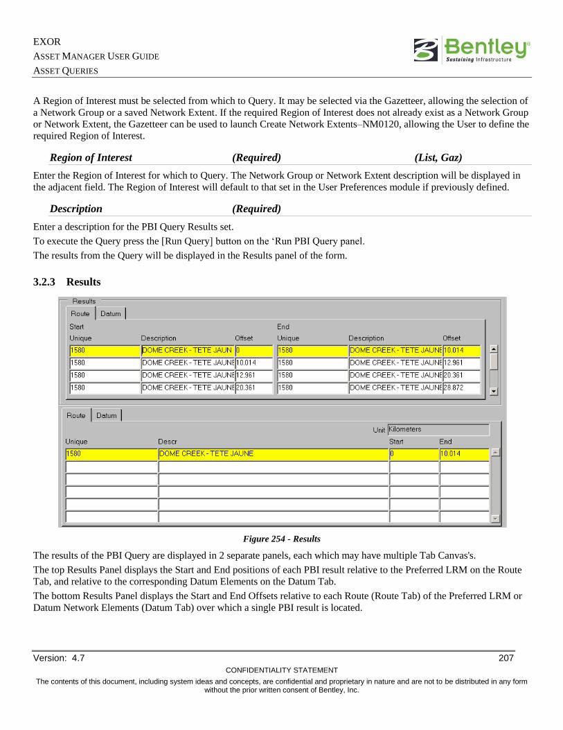
EXOR
ASSET MANAGER USER GUIDE
ASSET QUERIES
Version: 4.7 207
CONFIDENTIALITY STATEMENT
The contents of this document, including system ideas and concepts, are confidential and proprietary in nature and are not to be distributed in any form without the prior written consent of Bentley, Inc.
A Region of Interest must be selected from which to Query. It may be selected via the Gazetteer, allowing the selection of
a Network Group or a saved Network Extent. If the required Region of Interest does not already exist as a Network Group
or Network Extent, the Gazetteer can be used to launch Create Network Extents–NM0120, allowing the User to define the
required Region of Interest.
Region of Interest (Required) (List, Gaz)
Enter the Region of Interest for which to Query. The Network Group or Network Extent description will be displayed in
the adjacent field. The Region of Interest will default to that set in the User Preferences module if previously defined.
Description (Required)
Enter a description for the PBI Query Results set.
To execute the Query press the [Run Query] button on the ‘Run PBI Query panel.
The results from the Query will be displayed in the Results panel of the form.
3.2.3 Results
Figure 254 - Results
The results of the PBI Query are displayed in 2 separate panels, each which may have multiple Tab Canvas's.
The top Results Panel displays the Start and End positions of each PBI result relative to the Preferred LRM on the Route
Tab, and relative to the corresponding Datum Elements on the Datum Tab.
The bottom Results Panel displays the Start and End Offsets relative to each Route (Route Tab) of the Preferred LRM or
Datum Network Elements (Datum Tab) over which a single PBI result is located.

EXOR
ASSET MANAGER USER GUIDE
ASSET QUERIES
Version: 4.7 208
CONFIDENTIALITY STATEMENT
The contents of this document, including system ideas and concepts, are confidential and proprietary in nature and are not to be distributed in any form without the prior written consent of Bentley, Inc.
3.2.4 Route Tab (middle panel)
Figure 255
The Route Tab displays the following information relating to the resultant PBI Results:
Start The Unique, Description and Offset of the Route of the preferred LRM on which the PBI result
starts.
End The Unique, Description and Offset of the Route of the preferred LRM on which the PBI result
ends.
If either the Start or End of a PBI Result occurs at a location which is not a member of a Route of the preferred LRM, the
message ' Parent Element not Found' will be displayed in the relevant description field. Figure 256 shows an example.
Figure 256
Note: The 'Route' Tab canvas will not be displayed if there is no User Preferred LRM, i.e., the Preferred LRM value is
set to ALL LRMS
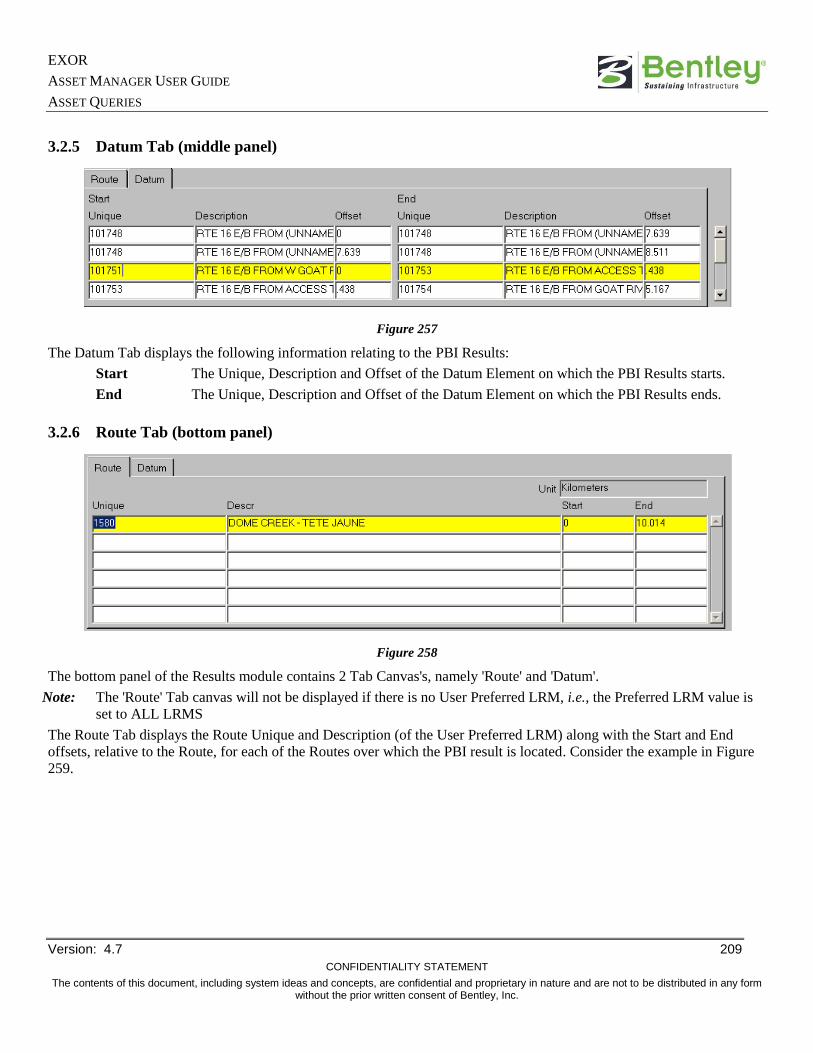
EXOR
ASSET MANAGER USER GUIDE
ASSET QUERIES
Version: 4.7 209
CONFIDENTIALITY STATEMENT
The contents of this document, including system ideas and concepts, are confidential and proprietary in nature and are not to be distributed in any form without the prior written consent of Bentley, Inc.
3.2.5 Datum Tab (middle panel)
Figure 257
The Datum Tab displays the following information relating to the PBI Results:
Start The Unique, Description and Offset of the Datum Element on which the PBI Results starts.
End The Unique, Description and Offset of the Datum Element on which the PBI Results ends.
3.2.6 Route Tab (bottom panel)
Figure 258
The bottom panel of the Results module contains 2 Tab Canvas's, namely 'Route' and 'Datum'.
Note: The 'Route' Tab canvas will not be displayed if there is no User Preferred LRM, i.e., the Preferred LRM value is
set to ALL LRMS
The Route Tab displays the Route Unique and Description (of the User Preferred LRM) along with the Start and End
offsets, relative to the Route, for each of the Routes over which the PBI result is located. Consider the example in Figure
259.

EXOR
ASSET MANAGER USER GUIDE
ASSET QUERIES
Version: 4.7 210
CONFIDENTIALITY STATEMENT
The contents of this document, including system ideas and concepts, are confidential and proprietary in nature and are not to be distributed in any form without the prior written consent of Bentley, Inc.
Figure 259
A PBI Query has been run over an extent of network that contains Datum Elements D1 to D7 and has returned 2 PBI
result 'chunks' represented by PB1 and PB2. A Preferred LRM has been defined of type 'ROUT'. Since PBI result PB1
spans Multiple Routes of that LRM, the Route Tab would display the Start and End Measure details of PBI result PB1
relative to each of the Routes of Type 'ROUT' over which the PBI result is located. Table 6 shows the details that may be
displayed for PBI result PB1.
Table 6
Unique Description Start End
R1 Route 1 50 250
R2 Route 2 0 300
R3 Route 3 0 80
The Unit of Measurement for the LRM is displayed in the Unit field.
3.2.7 Datum Tab (bottom panel)
Figure 260
The Datum Tab displays the Unique and Description along with the Start and End offsets for each of the Datum Network
Elements over which the PBI Result is located.
The 'Measure' field displays the cumulative length measure of the PBI result. Figure 292 shows an example of a PBI
Result that spans 3 Datum Elements namely D1, D2 and D3.

EXOR
ASSET MANAGER USER GUIDE
ASSET QUERIES
Version: 4.7 211
CONFIDENTIALITY STATEMENT
The contents of this document, including system ideas and concepts, are confidential and proprietary in nature and are not to be distributed in any form without the prior written consent of Bentley, Inc.
Figure 261
The Measure values of the PBI result in the above example would be as follows:
Datum Start End Measure
D1 20 50 0
D2 0 30 30
D3 0 70 60
Note: Only PBI Queries solely based on continuous Asset Types will have a measure value.
The results of previously saved PBI queries may be viewed by using the PBI Jobs tab (Figure 262).
3.2.8 PBI Jobs
Figure 262 - PBI Jobs
This window will display the previously saved PBI queries for the Selected Query. The associated results set may be
viewed by selecting the required Job.
The information displayed for each PBI Job is as follows:
Network Group or Network Extent (Region of Interest)
Query Job Description
User who ran the Query
Date on which the Query was run
Time at which the Query was run.
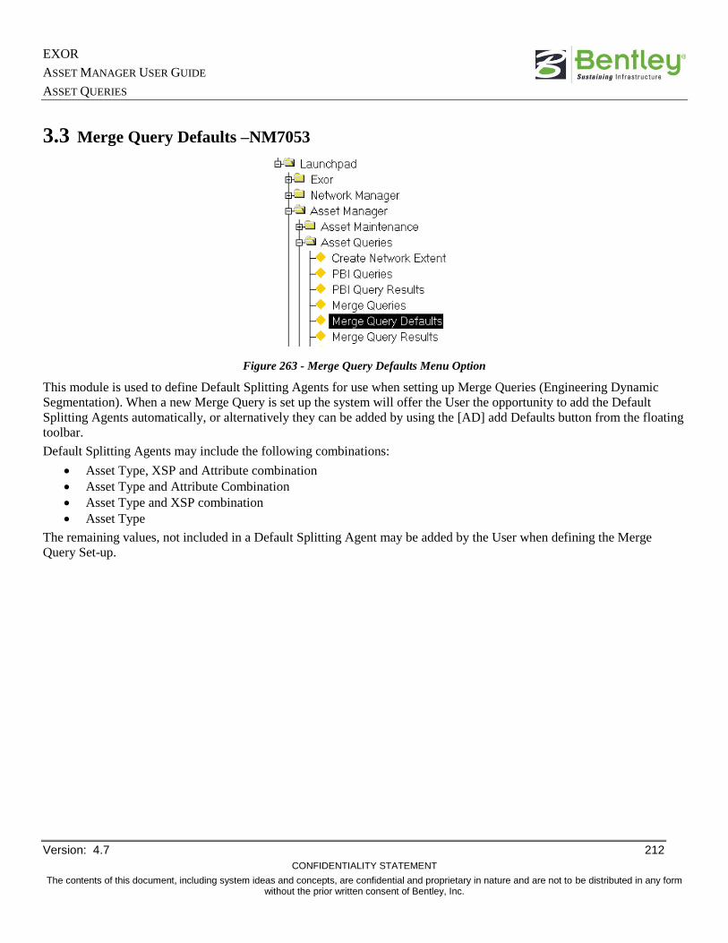
EXOR
ASSET MANAGER USER GUIDE
ASSET QUERIES
Version: 4.7 212
CONFIDENTIALITY STATEMENT
The contents of this document, including system ideas and concepts, are confidential and proprietary in nature and are not to be distributed in any form without the prior written consent of Bentley, Inc.
3.3 Merge Query Defaults –NM7053
Figure 263 - Merge Query Defaults Menu Option
This module is used to define Default Splitting Agents for use when setting up Merge Queries (Engineering Dynamic
Segmentation). When a new Merge Query is set up the system will offer the User the opportunity to add the Default
Splitting Agents automatically, or alternatively they can be added by using the [AD] add Defaults button from the floating
toolbar.
Default Splitting Agents may include the following combinations:
Asset Type, XSP and Attribute combination
Asset Type and Attribute Combination
Asset Type and XSP combination
Asset Type
The remaining values, not included in a Default Splitting Agent may be added by the User when defining the Merge
Query Set-up.

EXOR
ASSET MANAGER USER GUIDE
ASSET QUERIES
Version: 4.7 213
CONFIDENTIALITY STATEMENT
The contents of this document, including system ideas and concepts, are confidential and proprietary in nature and are not to be distributed in any form without the prior written consent of Bentley, Inc.
3.3.1 Merge Query Defaults
Figure 264 - Merge Query Defaults
When you enter this form any Default Splitting Agents already defined will be displayed.
Asset Type (Required) List
Select the Asset Type to use as a Default Splitting Agent. The Asset Type description will be displayed in the adjacent
field.
XSP (Optional) List
If required, enter the Default XSP value for the selected Asset Type. The Asset XSP description will be displayed in the
adjacent field.
Note: Only XSP values associated with the Asset Type in XSP and Reversal Rules – NM0305, will be available.
Attributes (Optional) List
Select the Asset Attribute for the selected Asset Type to use as a Default Splitting Agent.
Banding (Optional) List
If the Attribute has had Banding applied in Asset Types – NM0410, these may be selected.

EXOR
ASSET MANAGER USER GUIDE
ASSET QUERIES
Version: 4.7 214
CONFIDENTIALITY STATEMENT
The contents of this document, including system ideas and concepts, are confidential and proprietary in nature and are not to be distributed in any form without the prior written consent of Bentley, Inc.
3.4 Merge Queries – NM7050
Figure 265 - Merge Query Menu Option
This module is used to set up queries for use in a ‘merge operation’. Merge Queries are referred to as ‘Engineering
Dynamic Segmentation’ (Engineering Dyn Seg) to avoid confusion with the Merge operation carried out on Network
Elements. Sometimes known as ‘Slice and Dice’ it allows an area of interest to be ‘split’ into numerous parts (composite
items) depending on the characteristics of those parts.
The ‘area of interest’ defined for a ‘merge’ operation may be a Network Group, e.g., a Route or a Saved Network Extent.
If the selected area of interest is a connected set of Network Elements, the resulting merge set will be ordered as it is
positioned ‘on the ground’, not necessarily by SLK or displacement. The area of interest selected may be a Network
Extent created as a result of a PBI query.
Unlike a PBI query that reports purely on the locations of Asset Items which meet the selected query parameters, a ‘merge
query’ takes into consideration the selected Attribute Values when forming the Result set. The Resulting set will be ‘split’
into numerous parts depending on the selected Attributes value used in the merge process. The Attributes and associated
Values selected for a merge are known as ‘Splitting Agents’.
The results of a merge process may also be split at Points of Equation and at the change in a Route depending on the
values set for Product Options MRGPOE and MRGROUTE respectively.
Consider an example.
A Network Extent has been created with an extent limit of Route Offset 100.07 –120 on the H052 – Brookton Highway. A
PBI query has been run on the Network Extent to report on Items of Pavement Original with a width of < 7.2m. The
resulting set can be displayed as follows:

EXOR
ASSET MANAGER USER GUIDE
ASSET QUERIES
Version: 4.7 215
CONFIDENTIALITY STATEMENT
The contents of this document, including system ideas and concepts, are confidential and proprietary in nature and are not to be distributed in any form without the prior written consent of Bentley, Inc.
Figure 266
The PBI query resulted in 3 ‘parts’ of the Network Extent being included in the Resultant Set, each with Items of PAOR
with a Width of less than 7.2m.
A Merge Query run on the same Network Extent with a Splitting Agent defined as Asset Type Pavement Original with a
Width attribute value of < 7.2m would return the following set of results.
Figure 267
The same extent of Network would be selected but would be split into separate composite items based on the Width
Attribute of the Pavement Original Item.
A merge may comprise of one Asset Type with one or more Attributes or many Asset Types with one or more defined
attributes. For example, a simple merge could be performed to include only the parts of the selected Network Extent
where the Pavement Original ‘Year’ Attribute is less than 1990, or a more complex merge could be performed where the
Pavement Original ‘Year’ Attribute is < 1990 having a Formation Type of Normal and where the Roughness value is less
than 35.
If multiple Attribute values are selected an ‘AND’ relationship is established and any subsequent Queries using this merge
set-up will select only Items whose Attribute values meet ALL of the defined Attribute Values.
If more than One Asset Type is selected as a Splitting Agent the Relationship between the Items may be defined as an
‘Inner Join’ (default) or as an ‘Outer Join’. The Join Type selected will affect the Merge Results.
If an Inner Join is specified the resulting composite Items of the Merge Query will not exist unless all splitting agents exist
at that point. Specifying an Outer join will result in a new composite Item even at positions where only one of the splitting
agents does not exist.
Consider the examples below.
The top diagram below shows the locations of Pavement Original Items on an extent of network. The Values for the
Width (m) Attribute are displayed
The middle diagram below shows the locations of Roughness Items on the same extent of network. The Roughness values
are shown.

EXOR
ASSET MANAGER USER GUIDE
ASSET QUERIES
Version: 4.7 216
CONFIDENTIALITY STATEMENT
The contents of this document, including system ideas and concepts, are confidential and proprietary in nature and are not to be distributed in any form without the prior written consent of Bentley, Inc.
The bottom diagram below shows the resultant set of a Merge Query where the Pavement Original Width Attribute is <
7.2 and the Roughness is <35. The Join Type was defined as an Inner Join
3.4.1.1 Example of Inner Join Results
Figure 268
The same Merge Query where the Join Type was specified as an Outer Join would result in the following Result Set.

EXOR
ASSET MANAGER USER GUIDE
ASSET QUERIES
Version: 4.7 217
CONFIDENTIALITY STATEMENT
The contents of this document, including system ideas and concepts, are confidential and proprietary in nature and are not to be distributed in any form without the prior written consent of Bentley, Inc.
3.4.1.2 Example of Outer Join
Figure 269
Once a Merge Query has been defined it can be saved for reuse. The query can be executed using Merge Results–
NM7051, which can be launched using the [Run Merge] button on the form or from the Highways menu.
3.4.2 Attribute Bandings
‘Banded’ Asset Item Attribute and associated Asset Item Types may be used as a ‘Splitting’ agent combination.
An Asset Attribute may have several different Bandings defined. For example, an Attribute to record pavement width may
have a Banding to ‘group’ values every half metre and another Banding to ‘group’ values every 1metre.
When an Asset Item Attribute Banding is used in a Merge Query Setup, the resultant Composite Items are ‘grouped’
together, according to the Band Widths specified in the Merge Query Setup, to form a single Composite Item within the
appropriate Band Width.
Note: Only Asset Attributes with a Format of NUMBER or DATE may be banded.

EXOR
ASSET MANAGER USER GUIDE
ASSET QUERIES
Version: 4.7 218
CONFIDENTIALITY STATEMENT
The contents of this document, including system ideas and concepts, are confidential and proprietary in nature and are not to be distributed in any form without the prior written consent of Bentley, Inc.
3.4.3 Merge Queries
Figure 270 Merge Query
The Merge Queries form comprises of 4 panels. These panels relate to the following information
First Panel Query Name, Description and Join Type and ‘Transient’ flag
Second Panel Asset Types
Third Panel Asset Attributes for the selected Type(s) and Attribute Bandings
Fourth Panel Attribute Value for the selected Attributes
When you enter this form the cursor sits in the ‘Unique’ field in the first Panel waiting for a new Merge Query to be set-
up or existing Merge Queries to be retrieved. To query back an existing merge Query set-up press the [Enter Query]
button on the menu toolbar (or press F7), enter some selection criteria, then press the [Execute Query] button (or press
F8).

EXOR
ASSET MANAGER USER GUIDE
ASSET QUERIES
Version: 4.7 219
CONFIDENTIALITY STATEMENT
The contents of this document, including system ideas and concepts, are confidential and proprietary in nature and are not to be distributed in any form without the prior written consent of Bentley, Inc.
Figure 271 - Query Panel
Unique (Required)
Enter a Unique Reference for the PBI Query Set-up. A maximum of 30 characters is allowed.
Description (Required)
Enter a Description for the PBI Query Set-up. A maximum of 80 characters is allowed.
Join Type (Checkbox, Default)
Select the required Join Type for the Merge Query. If an Inner Join is specified the resulting composite Items of the
Merge Query will not exist unless all splitting agents exist at that point. Specifying an Outer join will result in a new
composite Item even at positions where only one of the splitting agents does not exist.
Transient (Checkbox)
Select this Flag if the resulting sets of the Merge Query may be deleted by running a Batch Job to remove all Merge
Query results with this flag set.
To define the required User Roles to access the Merge Query and its result sets press the [Roles] button.

EXOR
ASSET MANAGER USER GUIDE
ASSET QUERIES
Version: 4.7 220
CONFIDENTIALITY STATEMENT
The contents of this document, including system ideas and concepts, are confidential and proprietary in nature and are not to be distributed in any form without the prior written consent of Bentley, Inc.
3.4.4 Merge Query Roles
Figure 272 - Merge Query Roles
Each Merge Query must have at least one User Role associated with it. In order for a User to access the Merge Query and
it’s Results set, they must previously have been granted at least one of the User Roles defined for the Query. The Mode of
access a User has to a Merge Query will be determined by the Mode associated with the Merge Query Role. This will
allow a User with ‘Normal’ access to Read/Execute and Update the Merge Query, whereas a User with ‘Readonly’ access
may only Read and Execute the Query.
Note: The Mode of access granted to the User Role for the Merge Query will take precedence over the Mode of access
granted to the Module in HIG1880 – Modules, or HIG1836 – Roles.
A user must also satisfy the Role based security on the Asset Types used within the Query in order to access the Merge
Query or its Result Set, i.e., a User must have been granted access to ALL necessary Roles to see ALL the Asset Types
that are used within the Query.
The results of a Merge Query are further secured by the Admin Units associated with a User. For more information on
Merge Security refer to page 224 .

EXOR
ASSET MANAGER USER GUIDE
ASSET QUERIES
Version: 4.7 221
CONFIDENTIALITY STATEMENT
The contents of this document, including system ideas and concepts, are confidential and proprietary in nature and are not to be distributed in any form without the prior written consent of Bentley, Inc.
Figure 273 - Asset Type Panel
This panel is used to specify the Asset Types to be included as Splitting Agents in the merge Query and the required XSP
values. If more than one Asset Type is selected the relationship between the Types will be as defined by the Join Type.
When the User first enters this panel a message will be displayed (Figure 274) offering the opportunity to select the
Default Merge Splitting Agents (set up in Merge Query Defaults – NM7053.)
Figure 274 - Default Merge Prompt
To add the Default Splitting Agents press [Yes]. To view the Default settings press the [Enter Query] button followed by
the [Execute Query] button on the menu toolbar. Default Splitting Agents will be indicated by the ‘Default’ checkbox
being selected.
Note: Only the Splitting Agents (Attributes) which the User has been granted Access to by virtue of the Role based
security imposed on Asset Types and Users will be available to the User for use when defining the Merge Query
Setup.
To view the Merge Query Defaults press the [View Defaults] button on the form. This will call Merge Query Defaults –
NM7053 in query only mode, i.e., no database updates are permitted.
Asset Type (Required) (List)
Enter the Asset Type to be queried. The Asset Type description will be displayed in the adjacent field.
Note: A User will only be permitted to select an Asset Type for which they have sufficient Admin Unit security
privileges. For example, if an Asset Type has an associated Admin Type of TNC, then the User must have an
Admin Unit of this Type in order for it to be selected.
XSP (Optional) (List)
The Query may be limited to a specific XSP by entering a value in this field. If no XSP is entered, all XSP values for the
selected Asset Type will be included in the Query definition.

EXOR
ASSET MANAGER USER GUIDE
ASSET QUERIES
Version: 4.7 222
CONFIDENTIALITY STATEMENT
The contents of this document, including system ideas and concepts, are confidential and proprietary in nature and are not to be distributed in any form without the prior written consent of Bentley, Inc.
Default (Checkbox)
If the Attribute has been added from the Merge Query Defaults the ‘Default’ checkbox will be selected.
To add another Asset Type press the [Create Record] button on the menu toolbar.
Figure 275 - Attributes
This panel is used to define the Attributes of the selected Asset Type to be used in the merge query
More than one attribute can be entered to further restrict the query. If multiple Attribute values are selected an ‘AND’
relationship is established and any subsequent Queries using this merge set-up will select only Items whose Attribute
values meet ALL of the defined Attribute Values. For example, a merge could be set-up to include the occurrences, within
a Region of Interest, of Pavement Original (PAOR) with a width of > 9.0m and a Base Material of Sand as one of the
splitting agents. For an Item to be selected in the merge, both of these conditions must be met.
Attribute (Required) (List)
Enter the Attribute of the currently selected Asset Type to be used in the Query. The List of Values will display only the
attributes for the currently selected Asset Type.
Condition (Optional) (List)
Enter the condition for the selected attribute. These are standard Oracle conditions and are set up and maintained using
Domains–HIG9120 and updating the PBI_CONDITION option.
Banding (Optional) (List)
If required, select the Attribute Banding from which to ‘group’ the Merge Query Results.
Figure 276 - Values
This panel is used to define the parameter values for the currently selected Attribute. For example, if Asset Type PAOR –
Pavement Original was being Queried for all Items with a Width of greater than 9m, a value of ‘9’ would be entered.

EXOR
ASSET MANAGER USER GUIDE
ASSET QUERIES
Version: 4.7 223
CONFIDENTIALITY STATEMENT
The contents of this document, including system ideas and concepts, are confidential and proprietary in nature and are not to be distributed in any form without the prior written consent of Bentley, Inc.
Value (Optional) (List)
Enter the required ‘Query’ value for the currently selected Attribute. If the attribute values are held in a Domain, the List
of Values may be called and the description of the selected value will be displayed. If the ‘Condition’ entered for the
Attribute is ‘BETWEEN’ enter the second value in the field below.
Before the Query is used it should be checked to ensure that the parameters entered are valid. This can be done by
pressing the [Validate Query] button on the form. A message will be displayed (Figure 277) if the Query is valid. If the
Query is Invalid an appropriate message will be displayed (Figure 278), allowing the User to correct the Query
Parameters.
Figure 277 - Valid Query
Figure 278 - Invalid Query
To execute the query ensure that it is first saved by pressing the [Save] button on the menu toolbar, then press the [Run
Query] button on the form. This will call PBI Query Results–NM7041 and allow a Region Of Interest to be selected.
If any of the selected parameters are amended after the Merge Set up has been ‘Run’ the message shown in Figure 279
will be displayed, warning the User that if the Query Setup is saved all Jobs associated with the query will be deleted.
Figure 279 - Warning Message
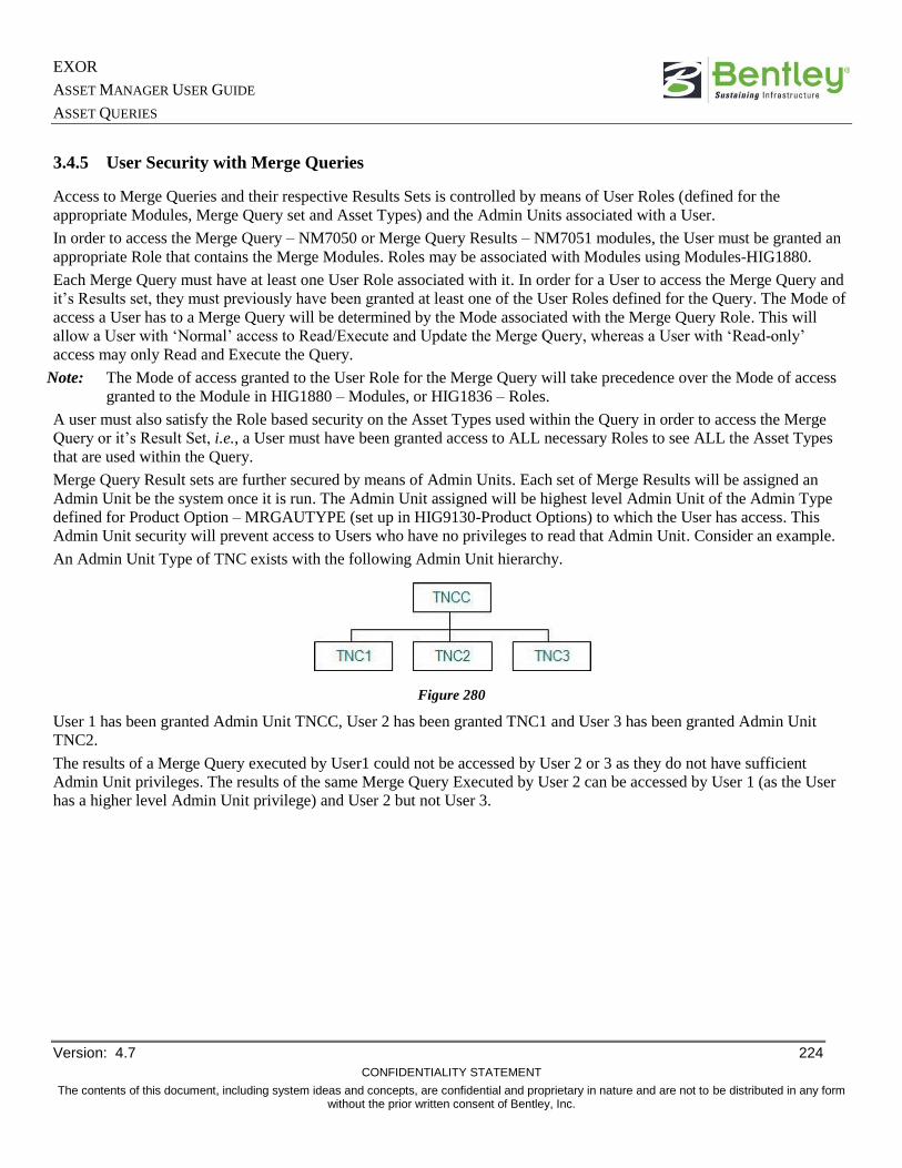
EXOR
ASSET MANAGER USER GUIDE
ASSET QUERIES
Version: 4.7 224
CONFIDENTIALITY STATEMENT
The contents of this document, including system ideas and concepts, are confidential and proprietary in nature and are not to be distributed in any form without the prior written consent of Bentley, Inc.
3.4.5 User Security with Merge Queries
Access to Merge Queries and their respective Results Sets is controlled by means of User Roles (defined for the
appropriate Modules, Merge Query set and Asset Types) and the Admin Units associated with a User.
In order to access the Merge Query – NM7050 or Merge Query Results – NM7051 modules, the User must be granted an
appropriate Role that contains the Merge Modules. Roles may be associated with Modules using Modules-HIG1880.
Each Merge Query must have at least one User Role associated with it. In order for a User to access the Merge Query and
it’s Results set, they must previously have been granted at least one of the User Roles defined for the Query. The Mode of
access a User has to a Merge Query will be determined by the Mode associated with the Merge Query Role. This will
allow a User with ‘Normal’ access to Read/Execute and Update the Merge Query, whereas a User with ‘Read-only’
access may only Read and Execute the Query.
Note: The Mode of access granted to the User Role for the Merge Query will take precedence over the Mode of access
granted to the Module in HIG1880 – Modules, or HIG1836 – Roles.
A user must also satisfy the Role based security on the Asset Types used within the Query in order to access the Merge
Query or it’s Result Set, i.e., a User must have been granted access to ALL necessary Roles to see ALL the Asset Types
that are used within the Query.
Merge Query Result sets are further secured by means of Admin Units. Each set of Merge Results will be assigned an
Admin Unit be the system once it is run. The Admin Unit assigned will be highest level Admin Unit of the Admin Type
defined for Product Option – MRGAUTYPE (set up in HIG9130-Product Options) to which the User has access. This
Admin Unit security will prevent access to Users who have no privileges to read that Admin Unit. Consider an example.
An Admin Unit Type of TNC exists with the following Admin Unit hierarchy.
Figure 280
User 1 has been granted Admin Unit TNCC, User 2 has been granted TNC1 and User 3 has been granted Admin Unit
TNC2.
The results of a Merge Query executed by User1 could not be accessed by User 2 or 3 as they do not have sufficient
Admin Unit privileges. The results of the same Merge Query Executed by User 2 can be accessed by User 1 (as the User
has a higher level Admin Unit privilege) and User 2 but not User 3.

EXOR
ASSET MANAGER USER GUIDE
ASSET QUERIES
Version: 4.7 225
CONFIDENTIALITY STATEMENT
The contents of this document, including system ideas and concepts, are confidential and proprietary in nature and are not to be distributed in any form without the prior written consent of Bentley, Inc.
3.5 Merge Query Results – NM7051
Figure 281 - Merge Query Results Menu Option
This module is used to select a Region of Interest on which to run the Merge Query and to view the Merge Query Results
that may be displayed by the User Preferred LRM (defined using the User Preferences–HIG1840 module). Merge Query
parameters will have already been defined using Merge Query Set-up–NM7040.
A Region of Interest may be selected via the Gazetteer, allowing the selection of a Network Group or a saved Network
Extent. If the required Region of Interest does not already exist as a Network Group or Network Extent, the Gazetteer can
be used to launch Create Network Extents–NM0120, allowing the User to define the required Region of Interest.
The Results from a Merge Query may be saved and viewed via the ‘Merge Jobs’ window. To extract a set of Merge
Results to an external file an Extract Definition may be defined using the Merge File Extract Definition – NM7055
module (see the Asset Manager System Admin Guide). Once the Merge Extract Definition has been defined a set of
Merge Results may be extracted using the Merge File Extract – NM7057 module that may be called using the [E] Extract
to File button on the floating toolbar in the Merge Query Results – NM7051 module or directly from a Exor menu option.

EXOR
ASSET MANAGER USER GUIDE
ASSET QUERIES
Version: 4.7 226
CONFIDENTIALITY STATEMENT
The contents of this document, including system ideas and concepts, are confidential and proprietary in nature and are not to be distributed in any form without the prior written consent of Bentley, Inc.
Figure 282 - PBI Query Results
When you enter this form the cursor sits in the ‘Query’ field waiting for a Merge Query to be selected. If the form has
been called from within Merge Query Set-up–NM7040, the selected Query will be automatically displayed.
Query (Required) (List)
Enter the Merge Query name to be run. The Merge Query description will be displayed in the field beneath the Query
name.

EXOR
ASSET MANAGER USER GUIDE
ASSET QUERIES
Version: 4.7 227
CONFIDENTIALITY STATEMENT
The contents of this document, including system ideas and concepts, are confidential and proprietary in nature and are not to be distributed in any form without the prior written consent of Bentley, Inc.
Figure 283 - Run Merge Query
A Region of Interest must be selected for which to Query. It is selected via the Gazetteer, allowing the selection of a
Network Group or a saved Network Extent. If the required Region of Interest does not already exist as a Network Group
or Network Extent, the Gazetteer can be used to launch Create Network Extents–NM0120, allowing the User to define the
required Region of Interest.
Region of Interest (Required) (List,Gaz)
Enter the Region of Interest for which to Query. The Network Group or Network Extent description will be displayed in
the adjacent field. The Region of Interest will default to that set in the User Preferences module if previously defined.
Description (Required)
Enter a description for the PBI Query Results set.
Domain Values (Radio Buttons)
If an Attribute which has an associated List of Values has been selected as a Splitting Agent the Asset results for the
Attribute may be displayed as either the Domain Code, the Domain Code Meaning or Both, by selecting the appropriate
radio button.
Figure 284 below shows an example of where the Domain Values Radio Button was set to ‘Both’ when the ‘Formation
Type’ Attribute of Asset Item Type ‘PAOR’ – Pavement Original was selected as a splitting Agent.
Figure 284 - Domain Value Example
To execute the Query press the [Run Query] button on the ‘Run Merge Query’ panel. The Results from the Query will be
displayed in the lower half of the form.

EXOR
ASSET MANAGER USER GUIDE
ASSET QUERIES
Version: 4.7 228
CONFIDENTIALITY STATEMENT
The contents of this document, including system ideas and concepts, are confidential and proprietary in nature and are not to be distributed in any form without the prior written consent of Bentley, Inc.
Figure 285 - Results
The results of the Merge Query are displayed in 2 separate panels each with multiple Tab Canvas's.
The top Results Panel displays the Start and End positions of each Merge Section relative to the Preferred LRM on the
Route Tab, and relative to the corresponding Datum Elements on the Datum Tab.
The bottom Results Panel displays the Start and End Offsets relative to each Route (Route Tab) of the Preferred LRM or
Datum Network Elements (Datum Tab) over which a single Merge Section is located.
The Asset Tab of the bottom Results Panel shows the selected Attributes and ‘qualifying’ values of each of the Attributes
selected as Splitting Agents in the Merge Query setup.
3.5.1 Route Tab (middle panel)
Figure 286
The Route Tab displays the following information relating to the resultant Merge Sections:
Start The Unique, Description and Offset of the Route of the preferred LRM on which the Merge
Section starts.

EXOR
ASSET MANAGER USER GUIDE
ASSET QUERIES
Version: 4.7 229
CONFIDENTIALITY STATEMENT
The contents of this document, including system ideas and concepts, are confidential and proprietary in nature and are not to be distributed in any form without the prior written consent of Bentley, Inc.
End The Unique, Description and Offset of the Route of the preferred LRM on which the Merge
Section ends.
If either the Start or End of a Merge Section occurs at a location that is not a member of a Route of the preferred LRM, the
message ' Parent Element not Found' will be displayed in the relevant description field. Figure 287 shows an example.
Figure 287
Note: The 'Route' Tab canvas will not be displayed if there is no User Preferred LRM, i.e., the Preferred LRM value is
set to ALL LRMS
3.5.2 Datum Tab (middle panel)
Figure 288
The Datum Tab displays the following information relating to the resultant Merge Sections:
Start The Unique, Description and Offset of the Datum Element on which the Merge Section starts.
End The Unique, Description and Offset of the Datum Element on which the Merge Section ends.

EXOR
ASSET MANAGER USER GUIDE
ASSET QUERIES
Version: 4.7 230
CONFIDENTIALITY STATEMENT
The contents of this document, including system ideas and concepts, are confidential and proprietary in nature and are not to be distributed in any form without the prior written consent of Bentley, Inc.
3.5.3 Route Tab (bottom panel)
Figure 289
The bottom panel of the Results module contains 3 Tab Canvas's, namely 'Route', 'Datum' and 'Asset'.
Note: The 'Route' Tab canvas will not be displayed if there is no User Preferred LRM, i.e., the Preferred LRM value is
set to ALL LRMS
The Route Tab displays the Route Unique and Description (of the User Preferred LRM) along with the Start and End
offsets, relative to the Route, for each of the Routes over which the Merge Section is located. Consider the example in
Figure 290.
Figure 290
A Merge Query has been run over an extent of network that contains Datum Elements D1 to D7 and has returned 2 Merge
Sections represented by M1 and M2. A Preferred LRM has been defined of type 'ROUT'. Since Merge Section M1 spans
Multiple Routes of that LRM, the Route Tab would display the Start and End Measure details of Merge Section M1
relative to each of the Routes of Type 'ROUT' over which the Merge Section is located. Table 7 shows the details that
may be displayed for Merge Section M1
Table 7
Unique Description Start End
R1 Route 1 50 250
R2 Route 2 0 300
R3 Route 3 0 80
The Unit of Measurement for the LRM is displayed in the Unit field.

EXOR
ASSET MANAGER USER GUIDE
ASSET QUERIES
Version: 4.7 231
CONFIDENTIALITY STATEMENT
The contents of this document, including system ideas and concepts, are confidential and proprietary in nature and are not to be distributed in any form without the prior written consent of Bentley, Inc.
3.5.4 Datum Tab (bottom panel)
Figure 291
The Datum Tab displays the Unique and Description along with the Start and End offsets for each of the Datum Network
Elements over which the Merge Section is located.
The 'Measure' field displays the cumulative length measure of the Merge Section. Figure 292 shows an example of a
Merge Section that spans 3 Datum Elements namely D1, D2 and D3.
Figure 292
The Measure values of the Merge Section in the above example would be as follows:
Datum Start End Measure
D1 20 50 0
D2 0 30 30
D3 0 70 60
Note: Only Merge Queries solely based on continuous Asset Types will have a measure value.
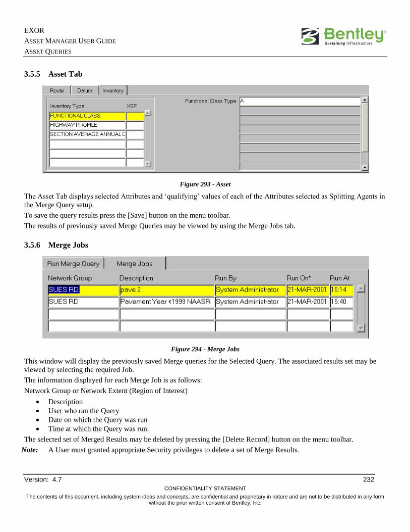
EXOR
ASSET MANAGER USER GUIDE
ASSET QUERIES
Version: 4.7 232
CONFIDENTIALITY STATEMENT
The contents of this document, including system ideas and concepts, are confidential and proprietary in nature and are not to be distributed in any form without the prior written consent of Bentley, Inc.
3.5.5 Asset Tab
Figure 293 - Asset
The Asset Tab displays selected Attributes and ‘qualifying’ values of each of the Attributes selected as Splitting Agents in
the Merge Query setup.
To save the query results press the [Save] button on the menu toolbar.
The results of previously saved Merge Queries may be viewed by using the Merge Jobs tab.
3.5.6 Merge Jobs
Figure 294 - Merge Jobs
This window will display the previously saved Merge queries for the Selected Query. The associated results set may be
viewed by selecting the required Job.
The information displayed for each Merge Job is as follows:
Network Group or Network Extent (Region of Interest)
Description
User who ran the Query
Date on which the Query was run
Time at which the Query was run.
The selected set of Merged Results may be deleted by pressing the [Delete Record] button on the menu toolbar.
Note: A User must granted appropriate Security privileges to delete a set of Merge Results.

EXOR
ASSET MANAGER USER GUIDE
ASSET QUERIES
Version: 4.7 233
CONFIDENTIALITY STATEMENT
The contents of this document, including system ideas and concepts, are confidential and proprietary in nature and are not to be distributed in any form without the prior written consent of Bentley, Inc.
3.5.7 Displaying Merge Query Results by User Preferred LRM
The results of a Merge Query may be displayed relative to any of the LRM's (Linear Referencing Methods) defined within
the Exor Network Model. The preferred LRM is set using the User Preferences–HIG1840 module (see the General User
Guide for more details) as shown in Figure 295 which may be called by pressing the Calendar Button on the Highways
Menu Toolbar as shown in Figure 296.
Figure 295
Figure 296
To display the Merge Result set in a different LRM reset the Preferred LRM value within the User Preferences module.
Note: The Merge Query DOES NOT have to be re-run.
If no LRM is selected, i.e., the Preferred LRM value is set to ALL LRMS; the Merge Results will be displayed relative to
the Datum Network Elements.
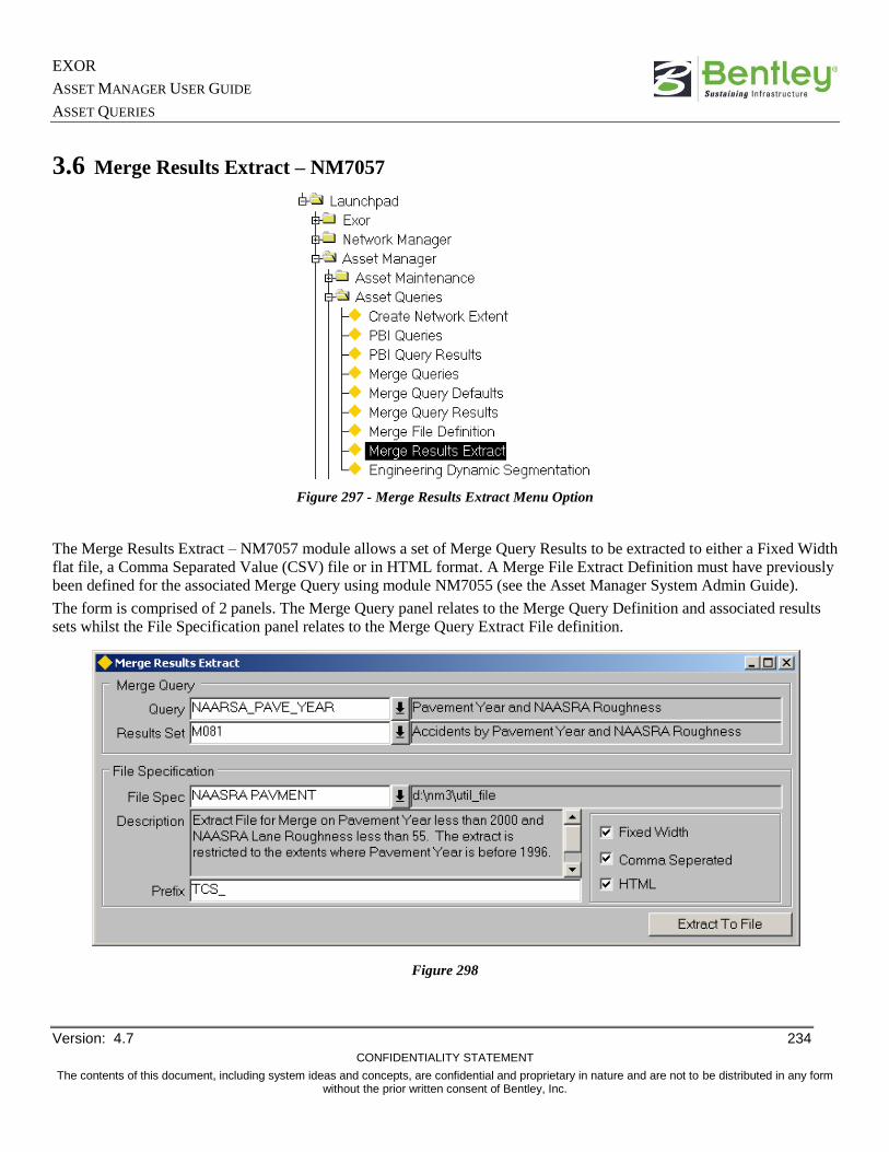
EXOR
ASSET MANAGER USER GUIDE
ASSET QUERIES
Version: 4.7 234
CONFIDENTIALITY STATEMENT
The contents of this document, including system ideas and concepts, are confidential and proprietary in nature and are not to be distributed in any form without the prior written consent of Bentley, Inc.
3.6 Merge Results Extract – NM7057
Figure 297 - Merge Results Extract Menu Option
The Merge Results Extract – NM7057 module allows a set of Merge Query Results to be extracted to either a Fixed Width
flat file, a Comma Separated Value (CSV) file or in HTML format. A Merge File Extract Definition must have previously
been defined for the associated Merge Query using module NM7055 (see the Asset Manager System Admin Guide).
The form is comprised of 2 panels. The Merge Query panel relates to the Merge Query Definition and associated results
sets whilst the File Specification panel relates to the Merge Query Extract File definition.
Figure 298

EXOR
ASSET MANAGER USER GUIDE
ASSET QUERIES
Version: 4.7 235
CONFIDENTIALITY STATEMENT
The contents of this document, including system ideas and concepts, are confidential and proprietary in nature and are not to be distributed in any form without the prior written consent of Bentley, Inc.
Query (Required) List
Select the required Merge Query from which to select a set of Merge results to be extracted. The list of allowable values
will be restricted to the Merge Queries to which the User has Role based security (see the Asset Manager System Admin
Guide for more information of Merge security).
The Merge Query description will be displayed in the adjacent field.
Results Set (Required) List
Select the required Merge Results set to be extracted.
The Merge Query Results description will be displayed in the adjacent field.
File Spec (Required) List
Select the required Merge Query Extract File definition. The list of values will be restricted to those Extract File
definitions associated with the selected Merge Query. Merge Extract Files are defined using the Merge File Extract
Definition – NM7055 module.
The Server File path of the Extract File and its description will be displayed.
Prefix (Optional)
If required, enter a prefix for the Extract File name.
Figure 299
The Merge Results may be extracted into one or all of the following file formats simultaneously:
Fixed Width
Comma Separated
HTML
Note: There is no significant degradation of performance when multiple file format extracts are specified.
Select the required file formats for the Extract. To execute the File Extract press the [Extract To File] button on the form.
The Extract file(s) will be created in the directory specified in the ‘Server File path’ field of the NM7055–Merge File
Extract Definition module. The filename format will be as follows:
<Prefix>_<Output Filename>.xxx
When the Extract Files have been created a message will be displayed to the User as displayed in Figure 300.

EXOR
ASSET MANAGER USER GUIDE
ASSET QUERIES
Version: 4.7 236
CONFIDENTIALITY STATEMENT
The contents of this document, including system ideas and concepts, are confidential and proprietary in nature and are not to be distributed in any form without the prior written consent of Bentley, Inc.
Figure 300
Figure 301 to Figure 303 show examples of each extract file type.
3.6.1 Example of Flat File Text Format Extract
Figure 301

EXOR
ASSET MANAGER USER GUIDE
ASSET QUERIES
Version: 4.7 237
CONFIDENTIALITY STATEMENT
The contents of this document, including system ideas and concepts, are confidential and proprietary in nature and are not to be distributed in any form without the prior written consent of Bentley, Inc.
3.6.2 Example of CSV Format Extract
Figure 302
3.6.3 Example of HTML Format
Figure 303

EXOR
ASSET MANAGER USER GUIDE
ASSET QUERIES
Version: 4.7 238
CONFIDENTIALITY STATEMENT
The contents of this document, including system ideas and concepts, are confidential and proprietary in nature and are not to be distributed in any form without the prior written consent of Bentley, Inc.
3.7 Merge File Extract Definition – NM7055
Figure 304 - Merge File Extract Definition Menu Option
The Merge File Extract Definition – NM7055 module is used to specify the information from the results of a Merge
Query to be extracted to an external file using Merge Results Extract – NM7057 (see the Asset Manager User Guide for
more information).
The Merge Results may be extracted into one, or all, of the following file formats simultaneously:
Fixed Width
Comma Separated
HTML
Note: There is no significant degredation of performance when multiple file format extracts are specified in the Merge
Results Extract – NM7057 module.
Each Merge File Extract definition is applicable only to the Merge Query specified in the ‘Merge Query’ field and has a
single Output file name, although this Filename may be prefixed when Extracting a set of Merge Results.
When a new Merge Query is defined using Merge Query Setup – NM7050, 4 new Database views are created. The Merge
File Extract Definition uses these Views as the source of the required information. The Database Views are created using
the following naming conventions:
V_MRG_<Query Unique>
V_MRG_<Query Unique>_SEC
V_MRG_<Query Unique>_VAL
V_MRG_<Query Unique>_VLS
For example a Merge Query with a Name of EXOR would result in the following 4 views being created:
V_MRG_EXOR
V_MRG_EXOR_SEC
V_MRG_EXOR_VAL
V_MRG_EXOR_VLS

EXOR
ASSET MANAGER USER GUIDE
ASSET QUERIES
Version: 4.7 239
CONFIDENTIALITY STATEMENT
The contents of this document, including system ideas and concepts, are confidential and proprietary in nature and are not to be distributed in any form without the prior written consent of Bentley, Inc.
The View(s) available for selection as the Source of the Merge Query results in the ‘Src’ field is determined by whether
the ‘Join to Datum’ check box is selected. If the Merge File Extract requires locational information relating to the Datum
Elements, e.g., Datum Element Unique, Begin and End Offsets, the ‘Join to Datum’ checkbox should be selected. The
available ‘Source’ view will then be the V_MRG_<Query Unique> Database View. If the flag is selected, any
homogeneous ‘chunks’ of Network identified by the Merge Query, which span multiple Datum Network Elements will be
‘split’ and a separate row of data will be created in the Extract File for each Datum Element. Consider an example.
Figure 305 shows the results of a Merge Query based on Pavement Width. An homogeneous extent of network has been
identified which spans 3 Elements.
Table 8 shows the results of an Extract File where the ‘Join to Datum’ flag has not been selected. Table 9 shows the
results of the same Extract File but where the ‘Join to Datum’ flag has been selected.
Figure 305
Table 8
Route Begin Offset End Offset Width
M081 0 6.39 7.2
Table 9
Element Begin Offset End Offset Width
M081/1-S 0 4720 7.2
M081/2-S 0 670 7.2
M081/3-S 0 1000 7.2
Table 10 shows some of the available Columns within the V_MRG_<Query Unique> view.
Table 10
View Column Name Description
Attribute 1 Value The first attribute value used in the Merge Query.
Attribute 2 Value The second attribute value used in the Merge Query.
Attribute 3 Value The third attribute value used in the Merge Query.
Etc… The xxx attribute value used in the Merge Query.
NMS_OFFSET_NE_ID The NE_ID of the ‘Parent’ Route

EXOR
ASSET MANAGER USER GUIDE
ASSET QUERIES
Version: 4.7 240
CONFIDENTIALITY STATEMENT
The contents of this document, including system ideas and concepts, are confidential and proprietary in nature and are not to be distributed in any form without the prior written consent of Bentley, Inc.
View Column Name Description
OFFSET_NE_UNIQUE The Unique name of the ‘Parent’ Route
NMS_BEGIN_OFFSET Begin Offset of homogenous extent relative to parent Route
NMS_END_OFFSET End Offset of homogenous extent relative to parent Route
NQR_DATE_CREATED Date the Merge Query Result was created
NQR_DESCRIPTION Description of Merge Query Results
PNT_OR_CONT Point or Continuous Item Flag (P or C)
Attribute 1_COUNT The total number of Items for Attribute 1 within the homogeneous extent.
Attribute 2_COUNT The total number of Items for Attribute 2 within the homogeneous extent.
Attribute 3_COUNT The total number of Items for Attribute 3 within the homogeneous extent.
Etc…
NSM_NE_ID The NE_ID of the Datum Element on which the homogeneous extent is located
DATUM_NE_UNIQUE The Unique name of the Datum Element
NSM_BEGIN_MP Begin Offset of homogenous extent relative to Datum Element
NSM_END_MP End Offset of homogenous extent relative to Datum Element
When the ‘Join to Datum’ flag is not selected the V_MRG_<Query Unique>_SEC and V_MRG_<Query Unique>_VAL
Database Views are available as the ‘Source’ of the Merge Query Results.
The V_MRG_<Query Unique>_SEC view is essentially the source of the locational information of each homogenous
extent of Network identified by a Merge Query, whilst the V_MRG_<Query Unique>_VAL view provides the source for
the Asset Attributes used as ‘Splitting Agents’ in the Merge Query definition.
Table 11 shows some of the available Columns within the V_MRG_<Query Unique>_SEC view.
Table 11
View Column Name Description
NMS_OFFSET_NE_ID The NE_ID of the ‘Parent’ Route
NMS_BEGIN_OFFSET Begin Offset of homogenous extent relative to parent Route
NMS_END_OFFSET End Offset of homogenous extent relative to parent Route
NQR_DATE_CREATED Date the Merge Query Result was created
NQR_DESCRIPTION Description of Merge Query Results
PNT_OR_CONT Point or Continuous Item Flag (P or C)
Attribute 1_COUNT The total number of Items for Attribute 1 within the homogeneous extent.
Attribute 2_COUNT The total number of Items for Attribute 2 within the homogeneous extent.
Etc…
The V_MRG_<Query Unique>_SEC view contains a column for each of the Attributes used as ‘Splitting Agents’ in the
Merge Query definition. The naming convention of the Database View Columns is as follows:
<Asset Type Code>_<View Attribute>
for example: PAOR_PAVE_YEAR

EXOR
ASSET MANAGER USER GUIDE
ASSET QUERIES
Version: 4.7 241
CONFIDENTIALITY STATEMENT
The contents of this document, including system ideas and concepts, are confidential and proprietary in nature and are not to be distributed in any form without the prior written consent of Bentley, Inc.
where PAOR is the Asset Type code and PAVE_YEAR is the View Attribute name of Pavement Year Attribute.
or
<Asset Type Code>_<XSP>_<View Attribute>
if the Asset Item has an associated XSP
for example CORO_L_PAVE_YEAR
In addition to the Data available via the Merge Query Database Views, application specific Function Calls may also be
made to a Database Package named NM3NET to include associated Data held in other Database Tables within the File
Extract. For example, NM3NET.GET_NE_UNIQUE(NMS_OFFSET_NE_ID) and
NM3NET.GET_NE_DESCR(NMS_OFFSET_NE_ID) will return the Unique Name and Description of a Group
respectively based on its unique internal identity (NE_ID). Other Function Calls include:
NM3NET.GET_DATUM_ELEMENT_LENGTH
NM3NET.GET_START_NODE
NM3NET.GET_END NODE
Standard Oracle Formatting Functions may also be used, e.g., LTRIM(TO_CHAR(<fieldname>), ‘ ‘)
If Engineering Dynamic Segmentation has been implemented Function calls may also be made to a Database Package
named NM3ENG_DYNSEG to allow the following Engineering Dynamic Segmentation Analysis functions to be
included in the Merge Extract:
Mean Value
Variance
Biased Variance
Standard Deviation
Biased Standard Deviation
Median Value
Length Weighted Average
First Value
Last Value
Minimum Value
Maximum Value
Most Common Value
Most Frequent Value
Value Count
Full details of these functions including the syntax needed can be found on page 247.
For more information on available Function Calls contact Exor Support at [email protected]
Attribute Values within a Merge Query Result may be decoded in the Merge Extract definition. For example, if a Merge
Query definition included the ‘Accident Severity’ attribute of an Asset Type of ‘Accident’ which holds the Severity as a
Numeric Value, e.g., 1,2 or 3, the Accident Severity may be Decoded within the Merge Extract so as to output the
Severity Description, e.g. a value of ‘1’ is extracted as ‘Fatal’, ‘2’ as ‘Serious’ etc.
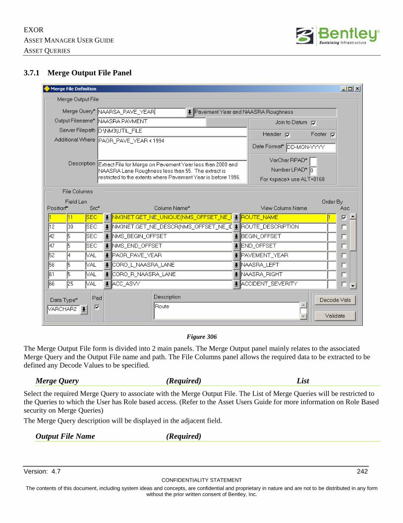
EXOR
ASSET MANAGER USER GUIDE
ASSET QUERIES
Version: 4.7 242
CONFIDENTIALITY STATEMENT
The contents of this document, including system ideas and concepts, are confidential and proprietary in nature and are not to be distributed in any form without the prior written consent of Bentley, Inc.
3.7.1 Merge Output File Panel
Figure 306
The Merge Output File form is divided into 2 main panels. The Merge Output panel mainly relates to the associated
Merge Query and the Output File name and path. The File Columns panel allows the required data to be extracted to be
defined any Decode Values to be specified.
Merge Query (Required) List
Select the required Merge Query to associate with the Merge Output File. The List of Merge Queries will be restricted to
the Queries to which the User has Role based access. (Refer to the Asset Users Guide for more information on Role Based
security on Merge Queries)
The Merge Query description will be displayed in the adjacent field.
Output File Name (Required)

EXOR
ASSET MANAGER USER GUIDE
ASSET QUERIES
Version: 4.7 243
CONFIDENTIALITY STATEMENT
The contents of this document, including system ideas and concepts, are confidential and proprietary in nature and are not to be distributed in any form without the prior written consent of Bentley, Inc.
Enter the required name for the Output File(s). This Output Filename may be prefixed when the results are extracted using
NM7057 – Merge Results Extract (refer to the Asset Users Guide for more information on the Merge Results Extract
module).
Server File path (Required, Default)
Enter the required path for the Output File. The Filepath will default to the value specified in Product Option
UTLFILEDIR.
This default Server Filepath may be amended if required and may be defined as any valid UNC address (Universal
naming Convention), e.g., \\cstewart\mergeoutputs
Note: Root directories cannot be specified as the Server Filepath.
Additional Where (Optional)
The data within the Merge Results set to be Extracted may be restricted by defining a ‘Where Clause’ in the Merge File
Extract Definition. Figure 306 shows an example where an Extract is being restricted to where the Pavement Year
(PAOR_PAVE_YEAR) is less than 1994. The values for VARCHAR attributes should be enclosed in single quotes.
Note: The word ‘WHERE’ is not required within the statement.
Description (Optional)
If required enter a description for the Merge Output File.
Join to Datum (Checkbox)
Check this box if Locational information relating to the Datum Network Elements is required. Refer to page 239 for more
information on the ‘Join To Datum’ option.
Header (Checkbox)
Check this box if a Header record is required on the Output File.
Note: A Header Record is only applicable to a ‘Fixed Width’ file and will not be created on an HTML or CSV File
Extract.
The format of the Header Record is as follows:
<000><Output Filename><YearMonthDay><Time>
for example,
0002NAASRA PAVMENT200203190841
where <000> is the record type, <2NAASRA PAVEMENT> is the Output Filename, <20020319> is the date on
which the Merge Extract File was created in the format of YYYYMMDD and <0841> is the time at which the Merge
Extract File was created.
Footer (Checkbox)
Check this box if a Footer record is required on the Output File.
Note: A Footer Record is only applicable to a ‘Fixed Width’ file and will not be created on an HTML or CSV File
Extract.
The format of the Footer Record is as follows:
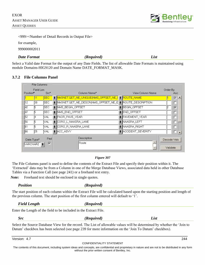
EXOR
ASSET MANAGER USER GUIDE
ASSET QUERIES
Version: 4.7 244
CONFIDENTIALITY STATEMENT
The contents of this document, including system ideas and concepts, are confidential and proprietary in nature and are not to be distributed in any form without the prior written consent of Bentley, Inc.
<999><Number of Detail Records in Output File>
for example,
999000002011
Date Format (Required) List
Select a Valid date Format for the output of any Date Fields. The list of allowable Date Formats is maintained using
module Domains-HIG9120 and Domain Name DATE_FORMAT_MASK.
3.7.2 File Columns Panel
Figure 307
The File Columns panel is used to define the contents of the Extract File and specify their position within it. The
‘Extracted’ data may be from a Column in one of the Merge Database Views, associated data held in other Database
Tables via a Function Call (see page 241) or a freehand text entry.
Note: Freehand text should be enclosed in single quotes.
Position (Required)
The start position of each column within the Extract File will be calculated based upon the starting position and length of
the previous column. The start position of the first column entered will default to ‘1’.
Field Length (Required)
Enter the Length of the field to be included in the Extract File.
Src (Required) List
Select the Source Database View for the record. The List of allowable values will be determined by whether the ‘Join to
Datum’ checkbox has been selected (see page 239 for more information on the ‘Join To Datum’ checkbox).

EXOR
ASSET MANAGER USER GUIDE
ASSET QUERIES
Version: 4.7 245
CONFIDENTIALITY STATEMENT
The contents of this document, including system ideas and concepts, are confidential and proprietary in nature and are not to be distributed in any form without the prior written consent of Bentley, Inc.
Column Name (Required) List
Select the required column from the selected Source view or enter a Function call. If a ‘freehand’ text string is required,
e.g., ‘End of File’ ensure that it is enclosed in single quotes.
Note: If a freehand text string is entered the choice of the Source View is unimportant.
View Column Name (Optional, Default)
Enter a Name for the Column. The name should comprises of Alphanumeric characters with no spaces, underscores are
allowable. This View Column Name will be used as the Column Heading if the File is extracted in HTML format. If no
value is added the View Column Name will default to a value of ‘COL_<start string position>, e.g., COL_110.
Note: If a Description is entered for the File Column, it will be used in preference to the View Column Name as the
Column Heading if the File is extracted in HTML format.
Order By (Optional)
The order in which the Merge Query Results Extract is sorted may be determined by specifying the sort priority against
the appropriate columns. Figure 307 shows an example of where the primary sort is carried out on the Route Name and a
secondary sort is performed on the Begin Offset Column.
Asc (Checkbox)
When an Order By is specified the default sort order will be in Ascending Order. Uncheck this box if descending Order is
required.
Figure 308
Data Type (Required) List
Select the Data Type of the data to be extracted. This must be the Data Type of the data as it will be presented in the
Extract File which may not necessarily be the same as the Data Type in the Merge Query Results. For example if a
TO_CHAR function is used to convert a numeric value to a VARCHAR the Data Type must be specified as a
VARCHAR2. Similarly if Decode Values are used to decode a Numeric Value to a text string the Data Type must be
specified as a VARCHAR2.
The ‘Dec. Places’, ‘Disp Dec. Pt’ and ‘Disp. Sign’ fields will only be displayed if the selected Data Type is ‘NUMBER’.
Pad (Checkbox)
Select this Checkbox if the Extract Column is to be padded to the specified Field Length. VARCHAR2 Columns will be
right padded with spaces whilst NUMBER columns will be left padded with zeros (0).
Dec. Places (Optional)
If the Data Type of the selected column is ‘NUMBER’ enter the number of decimal Places to be displayed in the Extract
File.

EXOR
ASSET MANAGER USER GUIDE
ASSET QUERIES
Version: 4.7 246
CONFIDENTIALITY STATEMENT
The contents of this document, including system ideas and concepts, are confidential and proprietary in nature and are not to be distributed in any form without the prior written consent of Bentley, Inc.
Disp Dec. Pt (Optional)
Select this Checkbox if a decimal point is to be displayed in the Extract File.
Note: If the number of decimal places is not Zero this checkbox must be selected.
Disp Sign (Optional)
Select this Checkbox to display a plus (+) or minus (-) sign infront of Numeric Values.
Description (Optional)
If required, enter a Description for the Column. If a value is entered it will be used in preference to the View Column
Name as the Column Heading if the File is extracted in HTML format.
3.7.3 Decode Values
Figure 309
Values from the Merge Query Results may be ‘decoded’ when they are Extracted to a file. Figure 309 shows an example
of where Accident Severity values are being decoded to a textural description of the value meaning.
Note: The Data Type for the Extract column must be the Data Type of the ‘To Value’.
To call the Decode Values dialogue for the selected File Column press the [Decode Vals] button on the form.
From Value (Required)
Enter the value from the Merge Query Results to be decoded.
To Value (Required)
Enter the ‘decoded’ value for the Merge Query Result.
Before the Merge Extract File Definition can be used it should be validated. This is done by pressing the [Validate]
button.
The results of a Merge Query may be extracted using module NM7057 – Merge Query Extract that may be called using
the [E] Extract to File button on the floating toolbar in the Merge Query Results – NM7051 module or directly from a
Exor menu option.
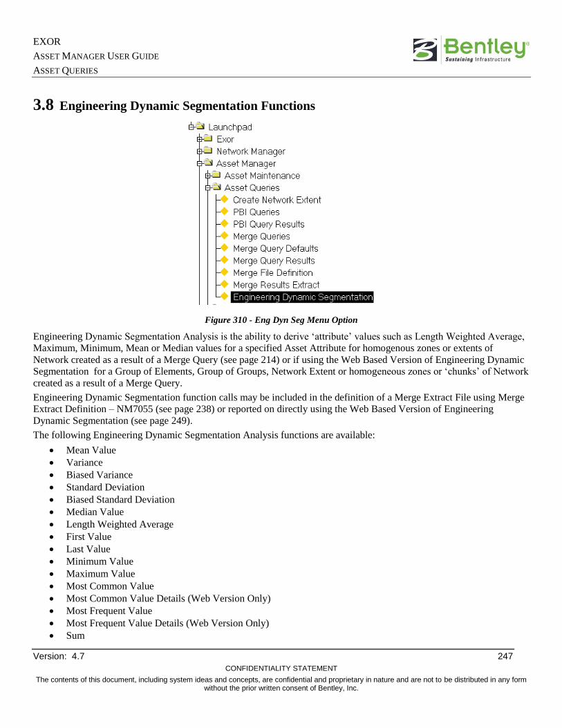
EXOR
ASSET MANAGER USER GUIDE
ASSET QUERIES
Version: 4.7 247
CONFIDENTIALITY STATEMENT
The contents of this document, including system ideas and concepts, are confidential and proprietary in nature and are not to be distributed in any form without the prior written consent of Bentley, Inc.
3.8 Engineering Dynamic Segmentation Functions
Figure 310 - Eng Dyn Seg Menu Option
Engineering Dynamic Segmentation Analysis is the ability to derive ‘attribute’ values such as Length Weighted Average,
Maximum, Minimum, Mean or Median values for a specified Asset Attribute for homogenous zones or extents of
Network created as a result of a Merge Query (see page 214) or if using the Web Based Version of Engineering Dynamic
Segmentation for a Group of Elements, Group of Groups, Network Extent or homogeneous zones or ‘chunks’ of Network
created as a result of a Merge Query.
Engineering Dynamic Segmentation function calls may be included in the definition of a Merge Extract File using Merge
Extract Definition – NM7055 (see page 238) or reported on directly using the Web Based Version of Engineering
Dynamic Segmentation (see page 249).
The following Engineering Dynamic Segmentation Analysis functions are available:
Mean Value
Variance
Biased Variance
Standard Deviation
Biased Standard Deviation
Median Value
Length Weighted Average
First Value
Last Value
Minimum Value
Maximum Value
Most Common Value
Most Common Value Details (Web Version Only)
Most Frequent Value
Most Frequent Value Details (Web Version Only)
Sum

EXOR
ASSET MANAGER USER GUIDE
ASSET QUERIES
Version: 4.7 248
CONFIDENTIALITY STATEMENT
The contents of this document, including system ideas and concepts, are confidential and proprietary in nature and are not to be distributed in any form without the prior written consent of Bentley, Inc.
Value Count (Merge Extract Only)
Value Distributions (Web Version Only)
This section of the Asset Manager User Guide details each of the available functions, describing the formula used and
necessary syntax for inclusion in the Merge File Extract Definition. For details on the Merge File Extract Definition –
NM7055 module refer to page 238 of this Guide or for details on the using the Web Based Version of Engineering
Dynamic Segmentation refer to page 267).

EXOR
ASSET MANAGER USER GUIDE
ASSET QUERIES
Version: 4.7 249
CONFIDENTIALITY STATEMENT
The contents of this document, including system ideas and concepts, are confidential and proprietary in nature and are not to be distributed in any form without the prior written consent of Bentley, Inc.
3.8.1 Mean (NM3ENG_DYNSEG.GET_MEAN_VALUE)
This function returns the Average (arithmetic mean) of the specified attribute values for each ‘chunk’ of network within
the selected region of interest. The formula used is:
Mean = ∑(x)
N
Where X is the attribute values and N is the number of values in the range.
Syntax (for use in Merge File Definition – NM7055)
NM3ENG_DYNSEG.GET_MEAN_VALUE(SEC.NQR_MRG_JOB_ID,SEC.NMS_MRG_SECTION_ID,'CORO','L
','IIT_NAASRA_LANE')
where ‘CORO’ is the required Asset Type, ‘L’ is the required XSP (optional) and ‘IIT_NAASRA_LANE’ is the
View Column Name for the required Attribute (as defined in Asset Metamodel – NM0410).
Figure 311 displays an example where the Mean roughness value is calculated for an Engineering Dynamic Segmentation
analysis on Traffic Sections and Roughness values.
Figure 311
The Mean Roughness for the Zone represented by T1 would be calculated as follows.
(30+25+22+31+28+30) = 27.66
6
Table 12
This function may be applied to attributes of the following Data Type Function may be used in
Number
Varchar
Date
Web Version – NMWEB0020
Merge Extract Definition – NM7055

EXOR
ASSET MANAGER USER GUIDE
ASSET QUERIES
Version: 4.7 250
CONFIDENTIALITY STATEMENT
The contents of this document, including system ideas and concepts, are confidential and proprietary in nature and are not to be distributed in any form without the prior written consent of Bentley, Inc.
3.8.2 Variance (NM3ENG_DYNSEG.GET_VARIANCE)
This function returns the Variance of the values of the specified attribute for each ‘chunk’ of network within the selected
region of interest. The Variance is a measure of how spread out a distribution is. It is computed as the average squared
deviation of each number from its Mean. The formula used is:
Variance = ∑(X–µ)²
N
Where X is the attribute value, µ is the Mean (see section 0) and N is the number of values in the range.
Syntax (for use in Merge File Definition – NM7055)
NM3ENG_DYNSEG.GET_VARIANCE(SEC.NQR_MRG_JOB_ID,SEC.NMS_MRG_SECTION_ID,'CORO','L','IIT_N
AASRA_LANE')
where ‘CORO’ is the required Asset Type, ‘L’ is the required XSP (optional) and ‘IIT_NAASRA_LANE’ is the View
Column Name for the required Attribute (as defined in Asset Metamodel – NM0410). Figure 312 displays an example
where the Variance for Roughness values is calculated for an Engineering Dynamic Segmentation analysis on Traffic
Sections and Roughness values.
Figure 312
The Variance of the Roughness values for the Zone represented by T1 would be calculated as follows:
∑((30–27.66)² + (25–27.66)² + (22–27.66)² + (31–27.66)² + (28–27.66)² + (30–27.66)²) = 10.22
6
Table 13
This function may be applied to attributes of the following Data Type Function may be used in
Number
Varchar
Date
Web Version – NMWEB0020
Merge Extract Definition – NM7055

EXOR
ASSET MANAGER USER GUIDE
ASSET QUERIES
Version: 4.7 251
CONFIDENTIALITY STATEMENT
The contents of this document, including system ideas and concepts, are confidential and proprietary in nature and are not to be distributed in any form without the prior written consent of Bentley, Inc.
3.8.3 Biased Variance (NM3ENG_DYNSEG.GET_BIASED_VARIANCE)
This function returns the Biased Variance of the values of the specified attribute for each ‘chunk’ of network within the
selected region of interest. The Biased Variance is a measure of how spread out a distribution is. It is computed as the
Biased Average squared deviation of each number from its Mean. The formula used is:
Biased Variance = ∑(X–µ)²
N-1
Where X is the attribute value, µ is the Mean and N is the number of values in the range.
Syntax (for use in Merge File Definition – NM7055)
NM3ENG_DYNSEG.GET_BIASED_VARIANCE(SEC.NQR_MRG_JOB_ID,SEC.NMS_MRG_SECTION_ID,'CO
RO','L','IIT_NAASRA_LANE')
where ‘CORO’ is the required Asset Type, ‘L’ is the required XSP (optional) and ‘IIT_NAASRA_LANE’ is the
View Column Name for the required Attribute (as defined in Asset Metamodel – NM0410).
Figure 313 displays an example where the Biased Variance for Roughness values is calculated for an Engineering
Dynamic Segmentation analysis on Traffic Sections and Roughness values.
Figure 313
The Biased Variance of the Roughness values for the Zone represented by T1 would be calculated as follows:
∑((30–27.66)² + (25–27.66)² + (22–27.66)² + (31–27.66)² + (28–27.66)² + (30–27.66)²) = 12.66
(6-1)
Table 14
This function may be applied to attributes of the following Data Type Function may be used in
Number
Varchar
Date
Web Version – NMWEB0020
Merge Extract Definition – NM7055

EXOR
ASSET MANAGER USER GUIDE
ASSET QUERIES
Version: 4.7 252
CONFIDENTIALITY STATEMENT
The contents of this document, including system ideas and concepts, are confidential and proprietary in nature and are not to be distributed in any form without the prior written consent of Bentley, Inc.
3.8.4 Standard Deviation (NM3ENG_DYNSEG.GET_STANDARD_DEVIATION)
This function returns the Standard Deviation of the values of the specified attribute for each ‘chunk’ of network within the
selected region of interest. The Standard Deviation is a measure of how widely values are dispersed from the average
value (the Mean) and is calculated as the square root of the Variance. The formula used is:
Standard Deviation = ∑(X–µ)²
N
where µ is the Mean and N is the number of values in the range.
Syntax (for use in Merge File Definition – NM7055)
NM3ENG_DYNSEG.GET_STANDARD_DEVIATION
(SEC.NQR_MRG_JOB_ID,SEC.NMS_MRG_SECTION_ID,'CORO','L','IIT_NAASRA_LANE')
where ‘CORO’ is the required Asset Type, ‘L’ is the required XSP (optional) and ‘IIT_NAASRA_LANE’ is the
View Column Name for the required Attribute (as defined in Asset Metamodel – NM0410).
Figure 314 displays an example where the Standard Deviation for Roughness values is calculated for an Engineering
Dynamic Segmentation analysis on Traffic Sections and Roughness values.
Figure 314
The Standard Deviation of the Roughness values for the Zone represented by T1 would be calculated as follows:
∑((30–27.66)² + (25–27.66)² + (22–27.66)² + (31–27.66)² + (28–27.66)² + (30–27.66)²) = 3.19
6
Table 15
This function may be applied to attributes of the following Data Type Function may be used in
Number
Varchar
Date
Web Version – NMWEB0020
Merge Extract Definition – NM7055

EXOR
ASSET MANAGER USER GUIDE
ASSET QUERIES
Version: 4.7 253
CONFIDENTIALITY STATEMENT
The contents of this document, including system ideas and concepts, are confidential and proprietary in nature and are not to be distributed in any form without the prior written consent of Bentley, Inc.
3.8.5 Biased Standard Deviation (NM3ENG_DYNSEG.GET_BIASED_STANDARD_DEVIATION)
This function returns the Biased Standard Deviation of the values of the specified attribute for each ‘chunk’ of network
within the selected region of interest. The Biased Standard Deviation is a measure of how widely values are dispersed
from the average value (the Mean) and is calculated as the square root of the Biased Variance. The formula used is:
Biased Standard Deviation = ∑(X–µ)²
N-1
where µ is the Mean and N is the number of values in the range.
Syntax (for use in Merge File Definition – NM7055)
NM3ENG_DYNSEG.GET_BIASED_STANDARD_DEVIATION(SEC.NQR_MRG_JOB_ID,SEC.NMS_MRG_SE
CTION_ID,'CORO','L','IIT_NAASRA_LANE')
where ‘CORO’ is the required Asset Type, ‘L’ is the required XSP (optional) and ‘IIT_NAASRA_LANE’ is the
View Column Name for the required Attribute (as defined in Asset Metamodel – NM0410).
Figure 315 displays an example where the Biased Standard Deviation for Roughness values is calculated for an
Engineering Dynamic Segmentation analysis on Traffic Sections and Roughness values.
Figure 315
The Biased Standard Deviation of the Roughness values for the Zone represented by T1 would be calculated as follows:
∑((30–27.66)² + (25–27.66)² + (22–27.66)² + (31–27.66)² + (28–27.66)² + (30–27.66)²) = 3.55
(6-1)
Table 16
This function may be applied to attributes of the following Data Type Function may be used in
Number
Varchar
Date
Web Version – NMWEB0020
Merge Extract Definition – NM7055

EXOR
ASSET MANAGER USER GUIDE
ASSET QUERIES
Version: 4.7 254
CONFIDENTIALITY STATEMENT
The contents of this document, including system ideas and concepts, are confidential and proprietary in nature and are not to be distributed in any form without the prior written consent of Bentley, Inc.
3.8.6 Median (NM3ENG_DYNSEG.GET_MEDIAN_VALUE)
This function returns the Median value of the values of the specified attribute for each ‘chunk’ of network within the
selected region of interest. The median is the number in the middle of a set of numbers; that is, half the numbers have
values that are greater than the median, and half have values that are less. If there is an even number in the set, then the
Median is calculated as the average of the two numbers in the middle.
Syntax (for use in Merge File Definition – NM7055)
NM3ENG_DYNSEG.GET_MEDIAN_VALUE(SEC.NQR_MRG_JOB_ID,SEC.NMS_MRG_SECTION_ID,'CORO','L','
IIT_NAASRA_LANE')
where ‘CORO’ is the required Asset Type, ‘L’ is the required XSP (optional) and ‘IIT_NAASRA_LANE’ is the View
Column Name for the required Attribute (as defined in Asset Metamodel – NM0410).
Figure 316 displays an example where the Median value for Roughness values is calculated for an Engineering Dynamic
Segmentation analysis on Traffic Sections and Roughness values.
Figure 316
The Median value for Roughness values for the Zone represented by T1 would be 29.
Table 17
This function may be applied to attributes of the following Data Type Function may be used in
Number
Varchar
Date
Web Version – NMWEB0020
Merge Extract Definition – NM7055

EXOR
ASSET MANAGER USER GUIDE
ASSET QUERIES
Version: 4.7 255
CONFIDENTIALITY STATEMENT
The contents of this document, including system ideas and concepts, are confidential and proprietary in nature and are not to be distributed in any form without the prior written consent of Bentley, Inc.
3.8.7 Length Weighted Average (NM3ENG_DYNSEG.GET_LENGTH_WEIGHTED_AVE)
This function returns the Length Weighted Average of the values of the values of the specified attribute for each ‘chunk’
of network within the selected region of interest. . The formula used is:
LWA = ∑(L*X)
∑ L
Where L is the length over which the each attribute value, X exists within the selected region of interest.
Syntax (for use in Merge File Definition – NM7055)
NM3ENG_DYNSEG.GET_LENGTH_WEIGHTED_AVE(SEC.NQR_MRG_JOB_ID,SEC.NMS_MRG_SECTION_
ID,'CORO','L','IIT_NAASRA_LANE')
where ‘CORO’ is the required Asset Type, ‘L’ is the required XSP (optional) and ‘IIT_NAASRA_LANE’ is the
View Column Name for the required Attribute (as defined in Asset Metamodel – NM0410).
Figure 317 displays an example where the Length Weighted Average for Roughness values is calculated for an
Engineering Dynamic Segmentation analysis on Traffic Sections and Roughness values.
Figure 317
The Length Weighted Roughness Average for the Zone represented by T1 would be calculated as follows.
(50*30) + (100*25) + (100*22) + (100*31) + (100*28)+ (40*30) = 27.14
(50+100+100+100+100+40)
Table 18
This function may be applied to attributes of the following Data Type Function may be used in
Number
Varchar
Date
Web Version – NMWEB0020
Merge Extract Definition – NM7055

EXOR
ASSET MANAGER USER GUIDE
ASSET QUERIES
Version: 4.7 256
CONFIDENTIALITY STATEMENT
The contents of this document, including system ideas and concepts, are confidential and proprietary in nature and are not to be distributed in any form without the prior written consent of Bentley, Inc.
3.8.8 First Value (NM3ENG_DYNSEG.GET_FIRST_VALUE)
This function returns the FIRST value encountered of the specified attribute for each ‘chunk’ of network within the
selected region of interest. In Figure 318 the First Value returned for the Traffic Section represented by T1 would be ‘30’.
Figure 318
Syntax (for use in Merge File Definition – NM7055)
NM3ENG_DYNSEG.GET_FIRST_VALUE(SEC.NQR_MRG_JOB_ID,SEC.NMS_MRG_SECTION_ID,'CORO','L'
,'IIT_NAASRA_LANE')
where ‘CORO’ is the required Asset Type, ‘L’ is the required XSP (optional) and ‘IIT_NAASRA_LANE’ is the
View Column Name for the required Attribute (as defined in Asset Metamodel – NM0410).
Table 19
This function may be applied to attributes of the following Data Type Function may be used in
Number
Varchar
Date
Web Version – NMWEB0020
Merge Extract Definition – NM7055

EXOR
ASSET MANAGER USER GUIDE
ASSET QUERIES
Version: 4.7 257
CONFIDENTIALITY STATEMENT
The contents of this document, including system ideas and concepts, are confidential and proprietary in nature and are not to be distributed in any form without the prior written consent of Bentley, Inc.
3.8.9 Last Value (NM3ENG_DYNSEG.GET_LAST_VALUE)
This function returns the LAST value encountered of the specified attribute for each ‘chunk’ of network within the
selected region of interest. In Figure 319 the Last Value returned for the Traffic Section represented by T1 would be ‘30’.
Figure 319
Syntax (for use in Merge File Definition – NM7055)
NM3ENG_DYNSEG.GET_LAST_VALUE(SEC.NQR_MRG_JOB_ID,SEC.NMS_MRG_SECTION_ID,'CORO','L',
'IIT_NAASRA_LANE')
where ‘CORO’ is the required Asset Type, ‘L’ is the required XSP (optional) and ‘IIT_NAASRA_LANE’ is the
View Column Name for the required Attribute (as defined in Asset Metamodel – NM0410).
Table 20
This function may be applied to attributes of the following Data Type Function may be used in
Number
Varchar
Date
Web Version – NMWEB0020
Merge Extract Definition – NM7055

EXOR
ASSET MANAGER USER GUIDE
ASSET QUERIES
Version: 4.7 258
CONFIDENTIALITY STATEMENT
The contents of this document, including system ideas and concepts, are confidential and proprietary in nature and are not to be distributed in any form without the prior written consent of Bentley, Inc.
3.8.10 Minimum Value (NM3ENG_DYNSEG.GET_MINIMUM_VALUE)
This function returns the Minimum Value for the selected Attribute for each ‘chunk’ of Network. In Figure 320 the
Minimum Roughness value returned for the Traffic Section represented by T1 would be ‘22’.
Figure 320
Syntax (for use in Merge File Definition – NM7055)
NM3ENG_DYNSEG.GET_MINIMUM_VALUE(SEC.NQR_MRG_JOB_ID,SEC.NMS_MRG_SECTION_ID,'CORO','
L','IIT_NAASRA_LANE')
where ‘CORO’ is the required Asset Type, ‘L’ is the required XSP (optional) and ‘IIT_NAASRA_LANE’ is the View
Column Name for the required Attribute (as defined in Asset Metamodel – NM0410).
Table 21
This function may be applied to attributes of the following Data Type Function may be used in
Number
Varchar
Date
Web Version – NMWEB0020
Merge Extract Definition – NM7055
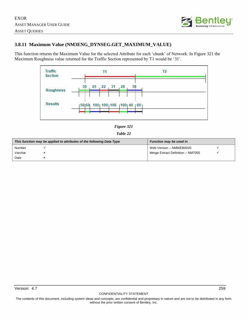
EXOR
ASSET MANAGER USER GUIDE
ASSET QUERIES
Version: 4.7 259
CONFIDENTIALITY STATEMENT
The contents of this document, including system ideas and concepts, are confidential and proprietary in nature and are not to be distributed in any form without the prior written consent of Bentley, Inc.
3.8.11 Maximum Value (NM3ENG_DYNSEG.GET_MAXIMUM_VALUE)
This function returns the Maximum Value for the selected Attribute for each ‘chunk’ of Network. In Figure 321 the
Maximum Roughness value returned for the Traffic Section represented by T1 would be ‘31’.
Figure 321
Table 22
This function may be applied to attributes of the following Data Type Function may be used in
Number
Varchar
Date
Web Version – NMWEB0020
Merge Extract Definition – NM7055

EXOR
ASSET MANAGER USER GUIDE
ASSET QUERIES
Version: 4.7 260
CONFIDENTIALITY STATEMENT
The contents of this document, including system ideas and concepts, are confidential and proprietary in nature and are not to be distributed in any form without the prior written consent of Bentley, Inc.
3.8.12 Most Common Value (NM3ENG_DYNSEG.GET_MOST_COMMON_VALUE)
This function returns the Most Common value for the selected Attribute for each ‘chunk’ of Network, i.e., the value that
exists over the greatest extent of each ‘chunk’ within the range.
In Figure 322 the Most Common Roughness value returned for the Traffic Section represented by T1 would be ‘22’ as it
exists over an extent of 110m.
Figure 322
Table 23
This function may be applied to attributes of the following Data Type Function may be used in
Number
Varchar
Date
Web Version – NMWEB0020
Merge Extract Definition – NM7055

EXOR
ASSET MANAGER USER GUIDE
ASSET QUERIES
Version: 4.7 261
CONFIDENTIALITY STATEMENT
The contents of this document, including system ideas and concepts, are confidential and proprietary in nature and are not to be distributed in any form without the prior written consent of Bentley, Inc.
3.8.13 Most Common Value Dets (NM3ENG_DYNSEG.GET_MOST_COMMON_VALUE_DETS)
This function returns Details of the Most Common value for the selected Attribute for each ‘chunk’ of Network, i.e., the
value that exists over the greatest extent of each ‘chunk’ within the range. The following details are returned:
The most common value
The total Length over which the most common value exists
The number of occurrences of the most common value
The %age of the total length of the most common value within each ‘chunk’ of network.
For the example shown in Figure 322 these values would respectively be:
22
110
1
22%
Table 24
This function may be applied to attributes of the following Data Type Function may be used in
Number
Varchar
Date
Web Version – NMWEB0020
Merge Extract Definition – NM7055

EXOR
ASSET MANAGER USER GUIDE
ASSET QUERIES
Version: 4.7 262
CONFIDENTIALITY STATEMENT
The contents of this document, including system ideas and concepts, are confidential and proprietary in nature and are not to be distributed in any form without the prior written consent of Bentley, Inc.
3.8.14 Most Frequent Value (NM3ENG_DYNSEG.GET_MOST_FREQUENT_VALUE)
This function returns the value with the most occurances within each ‘chunk’ of network within the selected region of
network.
In Figure 323 the Most Frequent Roughness value returned for the Traffic Section represented by T1 would be ‘30’ as it
occurs 2 times within the extent of the Traffic Section.
Figure 323
Table 25
This function may be applied to attributes of the following Data Type Function may be used in
Number
Varchar
Date
Web Version – NMWEB0020
Merge Extract Definition – NM7055

EXOR
ASSET MANAGER USER GUIDE
ASSET QUERIES
Version: 4.7 263
CONFIDENTIALITY STATEMENT
The contents of this document, including system ideas and concepts, are confidential and proprietary in nature and are not to be distributed in any form without the prior written consent of Bentley, Inc.
3.8.15 Most Frequent Value Dets (NM3ENG_DYNSEG.GET_MOST_FREQUENT_VALUE_DETS)
This function returns Details of the Most Frequent value for the selected Attribute for each ‘chunk’ of Network, i.e., the
value that exists over the greatest extent of each ‘chunk’ within the range. The following details are returned:
The most frequent value
The total Length over which the most frequent value exists
The number of occurrences of the most frequent value
The %age of the total length of the most frequent value within each ‘chunk’ of network.
For the example shown in Figure 322 these values would respectively be:
30
90
2
18%
Figure 324
This function may be applied to attributes of the following Data Type Function may be used in
Number
Varchar
Date
Web Version – NMWEB0020
Merge Extract Definition – NM7055

EXOR
ASSET MANAGER USER GUIDE
ASSET QUERIES
Version: 4.7 264
CONFIDENTIALITY STATEMENT
The contents of this document, including system ideas and concepts, are confidential and proprietary in nature and are not to be distributed in any form without the prior written consent of Bentley, Inc.
3.8.16 Sum (NM3ENG_DYNSEG.GET_SUM)
This function returns the simple sum of the specified Attribute for each 'chunk' of Network within the selected Region of
Interest.
The formula used is:
SUM = x
Where x is the attribute value
Syntax (for use in Merge File Definition – NM7055)
NM3ENG_DYNSEG.GET_SUM(SEC.NQR_MRG_JOB_ID,SEC.NMS_MRG_SECTION_ID,'TC','L','TC_COUNT'
)
where ‘TC’ is the required Asset Type, ‘L’ is the required XSP (optional) and ‘TC_COUNT’ is the View Column
Name for the required Attribute (as defined in Asset Metamodel – NM0410).
Figure 325 displays an example where the Sum of the Total Traffic Counts is calculated for an Engineering Dynamic
Segmentation analysis on Traffic Sections and Count values.
Figure 325
The Sum of the Count Values for the Zone represented by T1 would be calculated as follows:
30 + 25 + 22 + 31 + 28 + 30 = 166
Table 26
This function may be applied to attributes of the following Data Type Function may be used in
Number
Varchar
Date
Web Version – NMWEB0020
Merge Extract Definition – NM7055

EXOR
ASSET MANAGER USER GUIDE
ASSET QUERIES
Version: 4.7 265
CONFIDENTIALITY STATEMENT
The contents of this document, including system ideas and concepts, are confidential and proprietary in nature and are not to be distributed in any form without the prior written consent of Bentley, Inc.
3.8.17 Value Count (NM3ENG_DYNSEG.GET_VALUE_COUNT)
This function returns the number of occurrences of the selected Asset/Attribute and Value combination specified, for each
‘chunk’ of network within the selected region of network.
The example in Figure 326 would return a Value Count of 3 for the Traffic Section represented by ‘T1’ where the
Asset/Attribute and Value combination was specified as PAOR/Base Material and 2 (Gravel) respectively.
Figure 326
This function may be applied to attributes of the following Data Type Function may be used in
Number
Varchar
Date
Web Version – NMWEB0020
Merge Extract Definition – NM7055
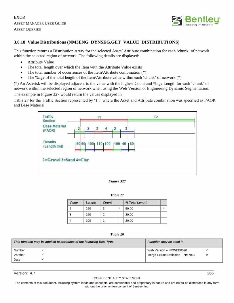
EXOR
ASSET MANAGER USER GUIDE
ASSET QUERIES
Version: 4.7 266
CONFIDENTIALITY STATEMENT
The contents of this document, including system ideas and concepts, are confidential and proprietary in nature and are not to be distributed in any form without the prior written consent of Bentley, Inc.
3.8.18 Value Distributions (NM3ENG_DYNSEG.GET_VALUE_DISTRIBUTIONS)
This function returns a Distribution Array for the selected Asset/ Attribute combination for each ‘chunk’ of network
within the selected region of network. The following details are displayed:
Attribute Value
The total length over which the Item with the Attribute Value exists
The total number of occurrences of the Item/Attribute combination (*)
The %age of the total length of the Item/Attribute value within each ‘chunk’ of network (*)
(*) An Asterisk will be displayed adjacent to the value with the highest Count and %age Length for each ‘chunk’ of
network within the selected region of network when using the Web Version of Engineering Dynamic Segmentation.
The example in Figure 327 would return the values displayed in
Table 27 for the Traffic Section represented by ‘T1’ where the Asset and Attribute combination was specified as PAOR
and Base Material.
Figure 327
Table 27
Value Length Count % Total Length
2 250 3 * 50.00 *
3 150 2 30.00
4 100 1 20.00
Table 28
This function may be applied to attributes of the following Data Type Function may be used in
Number
Varchar
Date
Web Version – NMWEB0020
Merge Extract Definition – NM7055

EXOR
ASSET MANAGER USER GUIDE
ASSET QUERIES
Version: 4.7 267
CONFIDENTIALITY STATEMENT
The contents of this document, including system ideas and concepts, are confidential and proprietary in nature and are not to be distributed in any form without the prior written consent of Bentley, Inc.
3.9 Web Based Engineering Dynamic Segmentation–NMWEB0020
Figure 328
3.9.1 General Information
Engineering Dynamic Segmentation Analysis is the ability to derive ‘attribute’ values such as Length Weighted Average,
Maximum,Minimum, Mean or Median values for a specified Asset Attribute for homogenous zones or extents of Network
created as a result of a Merge Query (see page 214) or for a Group of Elements, Group of Groups, Network Extent.
The following Engineering Dynamic Segmentation Analysis functions are available:
Mean Value
Variance
Biased Variance
Standard Deviation
Biased Standard Deviation
Median Value
Length Weighted Average
First Value
Last Value
Minimum Value
Maximum Value
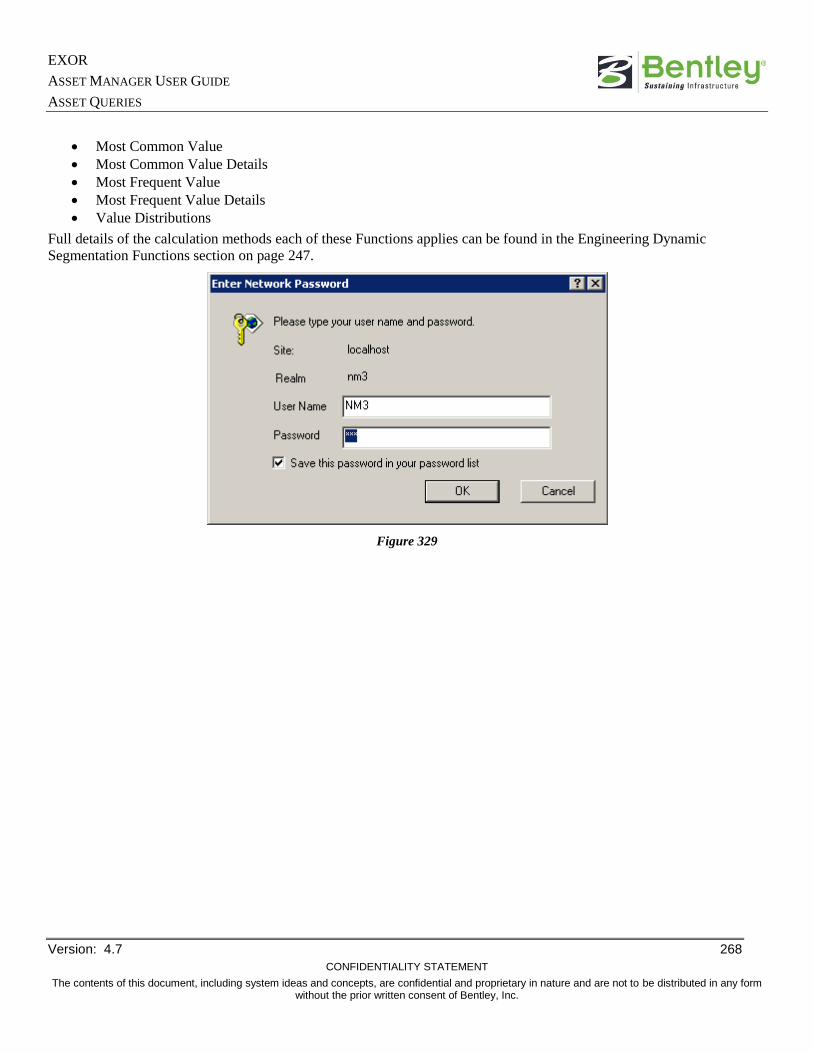
EXOR
ASSET MANAGER USER GUIDE
ASSET QUERIES
Version: 4.7 268
CONFIDENTIALITY STATEMENT
The contents of this document, including system ideas and concepts, are confidential and proprietary in nature and are not to be distributed in any form without the prior written consent of Bentley, Inc.
Most Common Value
Most Common Value Details
Most Frequent Value
Most Frequent Value Details
Value Distributions
Full details of the calculation methods each of these Functions applies can be found in the Engineering Dynamic
Segmentation Functions section on page 247.
Figure 329

EXOR
ASSET MANAGER USER GUIDE
ASSET QUERIES
Version: 4.7 269
CONFIDENTIALITY STATEMENT
The contents of this document, including system ideas and concepts, are confidential and proprietary in nature and are not to be distributed in any form without the prior written consent of Bentley, Inc.
3.9.2 Logging onto a Web Session
When either the Web Main Menu–NMWEB0000 or the Engineering Dynamic Segmentation (EDS)–NMWEB0020 is
opened your Web Browser will be called and a Dialogue displayed to allow the User to enter their Username and
Password. Once this is done and the [OK] button is pressed the first EDS page will be displayed as shown in Figure 330.
Figure 330
3.9.3 Hyper Links
A number of Links are included on each Web Page. These are namely:
Log Off (Hyperlink)
Logs the User out of the current Web Session.
Help (Hyperlink)

EXOR
ASSET MANAGER USER GUIDE
ASSET QUERIES
Version: 4.7 270
CONFIDENTIALITY STATEMENT
The contents of this document, including system ideas and concepts, are confidential and proprietary in nature and are not to be distributed in any form without the prior written consent of Bentley, Inc.
Calls the On-Line Help for the Current Web Form
About (Hyperlink)
Displays the Current Version of all Exor Products installed
Exor Corporation (Hyperlink)
Calls http://www.exorcorp.com/
Back (Hyperlink)
Goes back to previous page
Main Menu (Hyperlink)
Calls the Web Main Menu–NMWEB0000
3.9.4 Source of Area for EDS
Figure 331
This page allows the 'source' of the Network or Zones to be selected and the number of EDS Functions required for the
analysis to be defined.
The available options for the source of the Network or Zones are
Route (Radio Button)
Select this option if the EDS analysis is to be conducted over an entire Route, a specified Range within a Linear Route, a
Group of Groups or an individual Datum Network Element. If this option is selected, the Route, and if required the Start
and End Offsets on the selected Route, may be entered on the 'Functions' page, an extract of which is shown in Figure
332.

EXOR
ASSET MANAGER USER GUIDE
ASSET QUERIES
Version: 4.7 271
CONFIDENTIALITY STATEMENT
The contents of this document, including system ideas and concepts, are confidential and proprietary in nature and are not to be distributed in any form without the prior written consent of Bentley, Inc.
Figure 332
The Start and End Route Measures may be added if required to limit the Analysis to the specified range of Offsets.
Saved Network Extent (Radio Button)
Select this option if the EDS analysis is to be conducted over the a Saved Network Extent. If this option is selected the
required Network Extent may be selected from a List of Values on the 'Functions' page, an extract of which is shown in
Figure 333. The List of Values is restricted to only those Network Extents created by the User or Network Extents which
have been granted 'Public' ownership. The Network Extent description will be displayed in the adjacent field. See the
Network Manager User Guide for details on creating a Saved Network Extent.
Figure 333
Merge Results (Radio Button)
Select this option if the EDS analysis is to be conducted over the homogeneous 'chunks' of network or Zones created as a
result of a Merge Query (see page 247). If this option is selected the required Merge Query and Results Set may be
selected from a List of Values on the 'Functions' page, an extract of which is shown in Figure 334. The List of Values is
restricted to those Merge Queries and Results set to which the User has security privileges to access (see page 224 for
more information on Merge security). The Merge Query and Results Set Descriptions will be displayed in the adjacent
fields.
Figure 334
Number of Functions Required (Default)
Enter the maximum number of EDS Functions required for the analysis. The value entered will determine the number of
'Function' rows which are displayed on the 'Functions' page. Specifying more than the required number of EDS Functions
has no impact other than the speed the 'Functions' page is dynamically created and displayed to the User. The minimum
and maximum number of Function rows allowable are '2' and '100' respectively with the default being '5'.
To call the next page and specify the Function and Asset Type combinations required, press the [Continue] button.

EXOR
ASSET MANAGER USER GUIDE
ASSET QUERIES
Version: 4.7 272
CONFIDENTIALITY STATEMENT
The contents of this document, including system ideas and concepts, are confidential and proprietary in nature and are not to be distributed in any form without the prior written consent of Bentley, Inc.
Figure 335
3.9.5 Functions Page
This page allows the EDS Functions to be selected and the Asset Type/Attribute combination for which the Function is to
be applied to be defined. The page is dynamically created based upon the selected 'Area Source' and 'Number of Functions
Required' as specified in the previous page.
Function (Required) List
Select the required EDS Function. Full details and examples of what each Function does and the calculation methods used
can be found on page 247 along with the applicable Data Types the Function may be used against.
Asset Type (Required) List
Select the Asset Type for the EDS Function. The List of Values will be restricted to those Asset Types to which the User
has Role based access.
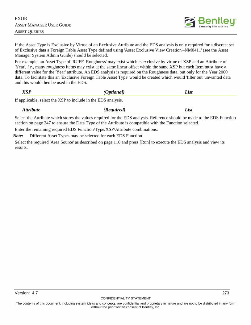
EXOR
ASSET MANAGER USER GUIDE
ASSET QUERIES
Version: 4.7 273
CONFIDENTIALITY STATEMENT
The contents of this document, including system ideas and concepts, are confidential and proprietary in nature and are not to be distributed in any form without the prior written consent of Bentley, Inc.
If the Asset Type is Exclusive by Virtue of an Exclusive Attribute and the EDS analysis is only required for a discreet set
of Exclusive data a Foreign Table Asset Type defined using 'Asset Exclusive View Creation'–NM0411' (see the Asset
Manager System Admin Guide) should be selected.
For example, an Asset Type of 'RUFF–Roughness' may exist which is exclusive by virtue of XSP and an Attribute of
'Year', i.e., many roughness Items may exist at the same linear offset within the same XSP but each Item must have a
different value for the 'Year' attribute. An EDS analysis is required on the Roughness data, but only for the Year 2000
data. To facilitate this an 'Exclusive Foreign Table Asset Type' would be created which would 'filter out' unwanted data
and this would then be used in the EDS.
XSP (Optional) List
If applicable, select the XSP to include in the EDS analysis.
Attribute (Required) List
Select the Attribute which stores the values required for the EDS analysis. Reference should be made to the EDS Function
section on page 247 to ensure the Data Type of the Attribute is compatible with the Function selected.
Enter the remaining required EDS Function/Type/XSP/Attribute combinations.
Note: Different Asset Types may be selected for each EDS Function.
Select the required 'Area Source' as described on page 110 and press [Run] to execute the EDS analysis and view its
results.

EXOR
ASSET MANAGER USER GUIDE
ASSET QUERIES
Version: 4.7 274
CONFIDENTIALITY STATEMENT
The contents of this document, including system ideas and concepts, are confidential and proprietary in nature and are not to be distributed in any form without the prior written consent of Bentley, Inc.
3.9.6 EDS Results
Figure 336
This page displays the results of the EDS analysis. A separate column is displayed for each of the selected EDS function
selected. A separate row is displayed for each homogeneous 'chunk' or zone of network selected in the Area Source
option. The example shown in Figure 336 is the result of an EDS analysis using the results of a Merge Query as the
Source Area.
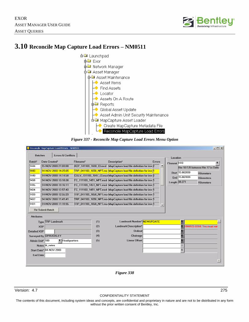
EXOR
ASSET MANAGER USER GUIDE
ASSET QUERIES
Version: 4.7 275
CONFIDENTIALITY STATEMENT
The contents of this document, including system ideas and concepts, are confidential and proprietary in nature and are not to be distributed in any form without the prior written consent of Bentley, Inc.
3.10 Reconcile Map Capture Load Errors – NM0511
Figure 337 - Reconcile Map Capture Load Errors Menu Option
Figure 338

EXOR
ASSET MANAGER USER GUIDE
ASSET QUERIES
Version: 4.7 276
CONFIDENTIALITY STATEMENT
The contents of this document, including system ideas and concepts, are confidential and proprietary in nature and are not to be distributed in any form without the prior written consent of Bentley, Inc.
3.10.1 Details
When you first enter the form all Batches with load errors are automatically retrieved. Navigate to, or query the batch you
are interested in as indicated by the email. For each batch there will be listed the batch id, the date the file was loaded, the
file name and description and the number of error records in the load.
Clicking on the Errors and Conflicts tab will List each of the assets to be loaded that have failed, and for each asset the
primary failure reason. The front screen shows the data as collected in the MapCapture Inspection
Figure 339
Although the primary reason is listed, all failures will be displayed in the form. There are many scenarios in which a
record could fail; these are listed later in this section.
Generally the major errors that could fail are
Invalid Asset attributes, either outside value ranges, not in domains or missing.
For each of the invalid attributes an error message will be shown against each attribute as shown in Figure 340.

EXOR
ASSET MANAGER USER GUIDE
ASSET QUERIES
Version: 4.7 277
CONFIDENTIALITY STATEMENT
The contents of this document, including system ideas and concepts, are confidential and proprietary in nature and are not to be distributed in any form without the prior written consent of Bentley, Inc.
Figure 340
Enter the correct value, or delete the record to not load this record.
Items where the asset in the database has been changed since the asset was inspected.
In this case the error highlighted will be as shown in Figure 341.
Figure 341
Pressing the Resolve Conflict button brings up the Resolve Conflict dialog as shown in Figure 342.

EXOR
ASSET MANAGER USER GUIDE
ASSET QUERIES
Version: 4.7 278
CONFIDENTIALITY STATEMENT
The contents of this document, including system ideas and concepts, are confidential and proprietary in nature and are not to be distributed in any form without the prior written consent of Bentley, Inc.
Figure 342
In this case you can see that the Comments field has been changed in the database. Use the radio buttons to select which
attributes you wish to save. Press the Resolve Button to update the save the changes and resubmit the batch.
Items where the network location has changed since the asset was inspected.
Pressing the Location Tab will bring up a form showing the existing location and the MapCapture surveyed location as
shown in Figure 343.

EXOR
ASSET MANAGER USER GUIDE
ASSET QUERIES
Version: 4.7 279
CONFIDENTIALITY STATEMENT
The contents of this document, including system ideas and concepts, are confidential and proprietary in nature and are not to be distributed in any form without the prior written consent of Bentley, Inc.
Figure 343
Note: IN THIS VERSION OF THE FORM THIS AREA IS NON UPDATABLE. YOU SHOULD USE THE
NETWORK AREA ON THE FRONT SCREEN TO UPDATE THE NETWORK AS APPROPRIATE.
This is due to the nature of NM3 and how it treats Asset locations. Research is on going as to how to best display and
modify location based information (Append an asset location, replace the whole asset, what happens if the survey didn’t
cover the whole of the location of the original asset, how other assets at the same location might be effected).
Verify the location of the asset on the main window, and then press the Resolve Conflict button to reload this asset
3.10.2 Known Issues
There are some known issues for which workarounds are available, but have not been included in this release. These are
listed below
Once a batch starts to be loaded it is locked by the load job. In certain unexpected fail circumstances if the load fails then
this lock is not released by the database. This is most common if the EDIF file is out of date. Currently, although you will
receive an email to this effect you cannot unlock the record through the form. This will be addressed in the next version
Location conflict resolution is still being investigated. Currently only a replace of network is available as discussed above.
Currently a network location is always generated by MapCapture and expected by the loader. Exor are currently working
on a solution to allow XY assets to be collected and loaded.
Similarly Assets that are not located against the network cannot be extracted for survey, as the extract routines run against
a route.
When updating a Route location using the Gazetteer the start and end offset will be replaced with the entire route, rather
than maintaining the surveyed measures.
Metamodel modifications are check across all asset types. Future versions will check the actual asset being loaded.
It is not possible to limit the usernames in the edif extract.

EXOR
ASSET MANAGER USER GUIDE
ASSET QUERIES
Version: 4.7 280
CONFIDENTIALITY STATEMENT
The contents of this document, including system ideas and concepts, are confidential and proprietary in nature and are not to be distributed in any form without the prior written consent of Bentley, Inc.
It is possible to update the start and end offsets of point items in NM0511 form under the Errors & Conflicts tab. Start and
end offsets have to be the same for point items.
Network Changes to a route are not currently detected and will not affect a data load. Exor are currently investigating
which network changes would invalidate the load process.
3.10.3 MapCapture Load Failures
Error Error Message Remedial Action Comments
EDIF date, header in much is < max last modified date in the asset model
HIG-0206: Load Aborted. Metadata changes have been made since the edif file was generated. found during processing of batch
Resurvey using new EDIF In future versions this will be applied on an asset by asset basis
Phase 1 Error–Incorrect data format (nulls where not null, varchar too long, number too large, invalid date)
Log File will have records with status X and Error Text for specific error, Bad file with the offending record.
This error should not occur unless the file has been modified by hand. If the metamodel has been changed then views should be recreated to reflect this. If the inspection edif is before the modification the hig-206 will be raised.
Phase 2 Error–Incorrect Asset data according to asset type metamodel. This can be values out of range, values not in domain
Log File will have records with status E and Error Text for specific error, Bad file with the offending record.
Open the Reconcile MapCapture Load Errors form (nm0511), navigate to the batch indicated and resolve the issues, resubmit the batch
Phase 2 Error–Invalid Road Network
Log File will have records with status E and Error Text for specific error, Bad file with the offending record.
NE_ID : 1301553 not found, neither on NM_ELEMENTS nor on NM_INV_ITEMS
Open the Reconcile Map Capture Load Errors form (nm0511), navigate to the batch indicated and enter/correct the Route reference.
Phase 2 Error–Update to a deleted Asset Item Log File will have records with status E and Error Text for specific error, Bad file with the offending record.
HIG-0067: Record not found: nm_inv_items (INV_ITEMS_ALL_PK) iit_ne_id =>
Phase 2 Error – Item Attribute /Route updated in Database since MC inspection
Log File will have records with status E and Error Text for specific error, Bad file with the offending record.
HIG-0208: Asset Update conflict. Changes have been made to the Asset in the database.
Open the Reconcile MapCapture Load Errors form (nm0511), navigate to the batch indicated click the reconcile errors button and select attributes to keep
Future Versions will check the values in the attributes to see if there are actually any differences between the surveyed data and the data held in the database (in case the change made in the DB is the same as that made in the field)

EXOR
ASSET MANAGER USER GUIDE
ASSET QUERIES
Version: 4.7 281
CONFIDENTIALITY STATEMENT
The contents of this document, including system ideas and concepts, are confidential and proprietary in nature and are not to be distributed in any form without the prior written consent of Bentley, Inc.
If you try and create more than one loader job per user
Hig 143 Only one loader job can be available, to avoid contention
Java file permissions are not set ORA-29532: Java call terminated by uncaught Java exception: java.security.AccessControlException: the Permission (java.io.FilePermission E:\UTL_FILE\MAPCAP80223.mch delete) has not been granted to NSG. The PL/SQL to grant this is dbms_java.grant_permission( 'NSG', 'SYS:java.io.FilePermission', 'E:\UTL_FILE\MAPCAP80223.mch', 'delete' )
Create the java permissions
UTL_FILE_DIR does not include the load area
HIG-0207: Load Aborted. Error found during MapCapture Load.
Set UTL_FILE_DIR
Batch Trailer file does not exist No error message Batch will not be loaded as it is not complete
Trail file format is incorrect The tail file format cannot be recognized
Alter the trail file format
Checksum in the trail file does not match the number of data files in the batch
Checksum does not match the data files found
The batch is locked No error message The batch is either being loaded by another process at the moment or failed to load
Phase 2 Error–Asset item being updated does not exist or has been end dated in NM3`
NE_ID : 1087619 not found, neither on NM_ELEMENTS nor on NM_INV_ITEMS
Phase 2 Error–Asset item has been updated in the database since the item was extracted to MapCapture
HIG-0208: Asset Update conflict. Changes have been made to the inventory in the database.
Open the Reconcile MapCapture Load Errors form (nm0511), navigate to the batch indicated and resolve the issues, resubmit the batch


