exocad Dental CAD OEM configuration guidecustomer.exocad.com/exocad_Instruction_Manual... · 2.5...
11
exocad.com Instruction Manual Information for scanner manufacturers .dentalProject: Project File Format English 01/2014
Transcript of exocad Dental CAD OEM configuration guidecustomer.exocad.com/exocad_Instruction_Manual... · 2.5...
exocad.com
Instruction ManualInformation for scanner manufacturers.dentalProject: Project File Format
Engl
ish
01/2
014

CONFIDENTIAL INFORMATION – NOT FOR END USERSIn your own interest, please do not leak this documentation to end users. Having end users tamper with complex configuration options may cause additional support overhead.© 2014 exocad GmbH
Instruction manual by exocad GmbH
© 2010 - 2014 exocad GmbH © 2007-2009 Fraunhofer IGD
Contact
Julius-Reiber-Str.37 64293 Darmstadt Germany
phone: +49-6151-629489-0 fax: +49-6151-629489-9
[email protected] exocad.com
Document version (author)
MKTIM-009-1401-en (mig), 2014-01-13

© 2014 by exocad GmbH | Julius-Reiber-Str. 37 | D-64293 Darmstadt Copying, publishing, extracting content or transfer to a third party is prohibited without agreement of exocad GmbH.
IM – .dentalProject: Project File Format
page 3/11
MKT
IM-0
09-14
01-e
n
Table of Contents
1. About the file format .dentalProject 4
2. Invocation of scanner software 4
3. A quick how-to 5
4. Detailed specification of the tags 6
5. Data storage 95.1 Distinguishing between upper- and lower jaw 95.2 OPTIONAL: Separate storage of single tooth scans 105.3 OPTIONAL: Separate storage of multi-tooth scans 10
6. Example for an XML file and desired behavior 11
© 2014 by exocad GmbH | Julius-Reiber-Str. 37 | D-64293 Darmstadt Copying, publishing, extracting content or transfer to a third party is prohibited without agreement of exocad GmbH.
IM – .dentalProject: Project File Format
page 4/11
MKT
IM-0
09-14
01-e
n
1. About the file format .dentalProject.dentalProject is a format for exchange of patient- and treatment related data in dental medicine. It is designed as an exchange format between the different modules of a CAD/CAM system: Database, scanner software, CAD software, CAM software.
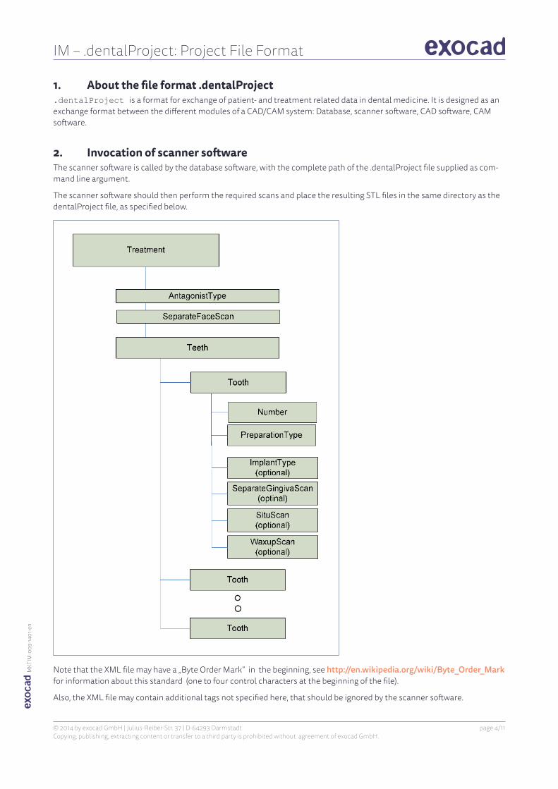
2. Invocation of scanner softwareThe scanner software is called by the database software, with the complete path of the .dentalProject file supplied as com-mand line argument.
The scanner software should then perform the required scans and place the resulting STL files in the same directory as the dentalProject file, as specified below.
Note that the XML file may have a „Byte Order Mark“ in the beginning, see http://en.wikipedia.org/wiki/Byte_Order_Mark for information about this standard (one to four control characters at the beginning of the file).
Also, the XML file may contain additional tags not specified here, that should be ignored by the scanner software.

© 2014 by exocad GmbH | Julius-Reiber-Str. 37 | D-64293 Darmstadt Copying, publishing, extracting content or transfer to a third party is prohibited without agreement of exocad GmbH.
IM – .dentalProject: Project File Format
page 5/11
MKT
IM-0
09-14
01-e
n
3. A quick how-toProgrammers hate long specifications. We know that.
Since this specification considers the special requirements of several scanners, it seems a bit complex at first glance, especi-ally as far as the naming options are concerned.
Therefore, this box gives you a quick suggestion for a stepwise, straightforward implementation.
1st step: Base functionality
Here, the scanner software only has to do the following:
● Read the list of teeth in the dentalProject file supplied on the command line. If teeth from the upper jaw are present (11-28), do a scan of the upper jaw model, and save it as <projectname>-upperjaw.stl in the project directory (where <projectname> is the name of the dentalProject file, excluding the .dentalProject extension). If teeth from the lower jaw are present (31-48), do a scan of the lower jaw model, and save it as <projectna-me>-lowerjaw.stl in the project directory (where <projectname> is the name of the dentalProject file passed on the command line, excluding the .dentalProject extension).
● If applicable for your scanner, you may use the „PreparationType“ (Crown, Inlay, Healthy) to chose the proper scanning strategy for a particular tooth, or for the work flow (e.g. „Now insert teeth 12, 14, 16“).
● Considering the type of antagonist scan: a) if AntagonistType=RegisteredJaws, additionally perform correct registration between upper- and jower jaw meshs. b) If AntagonistType=MushBite, perform an additional bite impression scan for the part of the jaw (upper or lower) that contains only teeth with PreparationType=Antagonist .
NOTEIf AntagonistType=MushBite and both jaw parts contain teeth with PreparationType not equal „Antagonist“, then display error message, if your scanner doesn‘t support the combination of mush bite AND upper/lower jaw scans at the same time. See the „3. Antagonist Type“ section below for information on scan data orientation (axes)
2nd Step: Multiple scans of the same model, properly registered
The goal is to scan the model multiple times, with certain parts removed or added. Example: Scan of a model with implants and removable gingiva mask. Here, you do two scans - one with scan abutments inserted and no gingiva mask, and one with gingiva mash but without scan abutments. Here, the sanner software should perform multiple scans, and correctly register them to each other, e.g. using common surfaces in the mesh / 3-point registration, or automatically if you get positional information from the scanner hard-ware. Additionally, a functionality for cropping single scans manually is desirable. Once this functionality is implemented, the following parts of our specification can be implemented easily:
● Separate gingiva scan (SeparateGingivaScan=true), save additional scan as <projectname>-gingiva.stl
● Situation model scan (SituScan=true), save additional scan as <projectname>-situ.stl
● implant-based constructions (ImplantType NOT „none“ or „StandardAbutment“), save additional scan as <projectfile>-marker.stl
3rd step: Support of the waxup feature (digital copy milling)
Here, the scanner software must perform an additional scan as described above, but all surfaces that are also in the main scan must be removed. That is, when loading model scan and waxup scan together, no duplicate surfaces may be present. Additionally, the waxup scan must be free of mesh errors and artefacts. Holes in the waxup scan, or incomplete measurement of the lower part of the waxup, are allowed though.

© 2014 by exocad GmbH | Julius-Reiber-Str. 37 | D-64293 Darmstadt Copying, publishing, extracting content or transfer to a third party is prohibited without agreement of exocad GmbH.
IM – .dentalProject: Project File Format
page 6/11
MKT
IM-0
09-14
01-e
n
4. Detailed specification of the tags
Tag Description
1. Treatment ● main structure, which contain all information relevant to the treatment. ● contains the information about all teeth. Each tooth has its own XML
block „Tooth“ within „Treatment“. ● contains an additional tag „AntagonistType“, die which specifies the desi-
red scanning/registration method of the antagonist, and a “SeparateFaceScan” tag which specifies if a textured 3D scan of the pati-ent’s face should be performed.
2. Tooth
2.1 Number is the two-digit tooth number, following the FDI scheme.
2.2. PreparationType The PreparationType specifies the type of preparation, or lack thereof. It should be used to choose the appropriate scanning method for this tooth.
Possible values are:
● Crown ● Inlay ● Pontic ● Missing ● Healthy ● Antagonist
Further types may be added in the future. If the PreparationType specified is unk-nown to scanner software, the user should be asked about the scan strategy to use, or a default scan strategy should be used.
2.3 Crown Tooth is prepared for crown/coping. This tooth should be scanned accurately. The scanner should make sure that the entire preparation margin and the part above it is visible in the scan, and without holes or mesh errors.
2.4 Inlay Tooth has an inlay preparation. This tooth should be scanned accurately. The scanner should make sure that the entire preparation margin and the part within it is visible in the scan, and without holes or mesh errors.
2.5 Pontic A tooth is missing here and should be replaced by a pontic. The scanner software should scan the gingiva imprint. Accuracy requirements are moderate.
Typically, these will be scanned with the „main scan“ (overview) and saved in the same file as other teeth (e.g. healthy teeth, see below).
Optional: In the case that the gingival scan is performed separately, the gingigva imprint can be saved in a separate file with the “-gingiva” tag (see “Data storage” below).
2.6 Missing A tooth is missing and should not be replaced. There is nothing to do for the scan-ner here.

© 2014 by exocad GmbH | Julius-Reiber-Str. 37 | D-64293 Darmstadt Copying, publishing, extracting content or transfer to a third party is prohibited without agreement of exocad GmbH.
IM – .dentalProject: Project File Format
page 7/11
MKT
IM-0
09-14
01-e
n
Tag Description
2.7 Healthy A healthy anterior tooth should be scanned. Healthy teeth do not need to be scanned with maximum accuracy, and holes in the scan are permissible to a certain degree. Accuracy requirements are moderate. However, decent accuracy is desired for:
Anterior teeth right next to a tooth that should be restored (PreparationTy-pe=Inlay,Crown,Pontic) should be scanned accurately on the side facing the tooth to be restored.
The occlusal area of the healthy tooth should be scanned accurately, especially if it is the antagonist of a tooth that is to be restored
Typically, healthy teeth will be scanned with the „main scan“ (overview scan).
2.8 Antagonist An antagonist should be scanned (either mush bite/registration bite scan, or scan of a separate stone model that is properly registered to the main scan). Files containing only teeth of type Antagonist can be tagged „-antagonist.stl“; see section “Data storage” below.
3. AntagonistType The „AntagonistType“ specifies how the antagonist should be scanned. It is only of importance if both upper and lower jaw contain tooth definitions; otherwise it should be ignored and no antagonist scan should be performed. The Antagonist-Type tag is within Treatment and is not tooth-specific.
The following values are possible:
● MushBite – scan only registration bite, not stone model of antagonist
Orientation of scan data for single model/impres-sion scan: The model containing preparations must be oriented in a way that the Z axis points into the occlusal direction of the prepared teeth (this is the default behavior for most scanners anyways)
● RegisteredJaws – scan stone models for upper and lower jaw and register them
Orientation of scan data for two-model scan: Both stone models scans must be correctly registered to each other and the Z axis should point upwards (rela-tive from the patient – that is, the Z axis points from the patient‘s feet to the patient‘s head). So, for the lower jaw, the occlusal axis corresponds the Z axis, and for the upper jaw the occlusal axis corresponds to the negative Z axis.
Relevant only for scanners that support scanning of articulated models:
● ArticulatorPforzheim – scan in Amann Girrbach Artex CR Articulator ● ArticulatorPforzheimLegacy - scan in Girrbach Artex AR Articulator ● ArticulatorBieberbach – Scan in KAVO Articulator ● ArticulatorMunich – Scan in SAM 3 Articulator ● ArticulatorMunichLegacy – Scan in SAM 2 Articulator

© 2014 by exocad GmbH | Julius-Reiber-Str. 37 | D-64293 Darmstadt Copying, publishing, extracting content or transfer to a third party is prohibited without agreement of exocad GmbH.
IM – .dentalProject: Project File Format
page 8/11
MKT
IM-0
09-14
01-e
n
Tag Description
4. ImplantType (optional) If the tag „ImplantType“ exists and is not “none“ or “StandardAbutment”, and additional scan with the scan abutment inserted should be performed. The scan abutment scan(s) should be tagged “-marker” in the filename; see section “Data storage” below for details.
Note on accuracy: Some scanners support a mode where first an overview scan is performed, then later certain parts are scanned individually, and then the individual scans are matched into the overview scan. This mode should NOT be used for marker scans, since the marker scan will only be used for matching with the scan abutment geometry in the CAD software. A duplicate matching process would reduce accuracy!
5. SeparateGingivaScan (optional)
If the tag „SeparateGingivaScan“ exists and is not „false“, then a separate scan containing only the gingiva should be performed. This is typically the case if a gingival has been modeled in silicone (common for implant-based constructions). The gingiva scan(s) should be tagged “-gingiva” in the filename; see section “Data storage” below for details.
6. SituScan (optional) If the tag „SituScan“ exists and is not „false“, then a separate scan of the situation model (typically wax model) should be performed. The situation model scan(s) should be tagged “-situ” in the filename; see section “Data storage” below for details.
7. SeparateWaxupScan (optional) situation model.
If the tag „SeparateWaxupScan“ exists and is not „false“, then a separate scan of the waxup should be performed. The waxup scan(s) should be tagged “-waxup” in the filename; see section “Data storage” below for details.
Difference between “Situ” and “Waxup” scan:In the CAD software, a situ scan is merely displayed as a help to the user. Automatic adaptation of the construction to the situ model is possible; however, the mesh of the situ model will not be directly used for the final construction. Require-ments regarding scan quality are low; holes etc are permissib-le. The situ scan may contain surfaces that are also present in the stone model scan.A waxup scan is directly used for the construction (“digital copy milling”). The requirements regarding scan quality are very high. The waxup scan may not contain surfaces that are also present in the stone model scan. Mesh errors, such as self-intersections, topology errors, or flipped triangle normals are not allowed.
© 2014 by exocad GmbH | Julius-Reiber-Str. 37 | D-64293 Darmstadt Copying, publishing, extracting content or transfer to a third party is prohibited without agreement of exocad GmbH.
IM – .dentalProject: Project File Format
page 9/11
MKT
IM-0
09-14
01-e
n
Tag Description
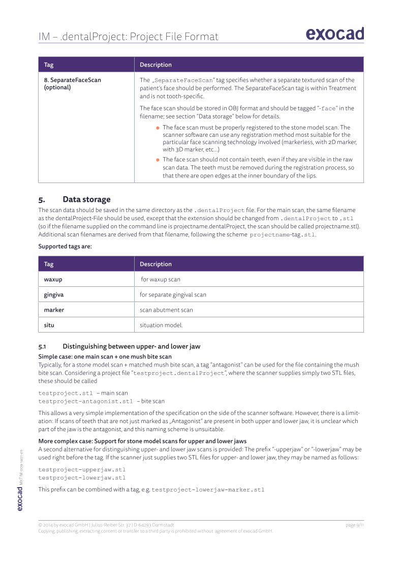
8. SeparateFaceScan (optional)
The „SeparateFaceScan“ tag specifies whether a separate textured scan of the patient’s face should be performed. The SeparateFaceScan tag is within Treatment and is not tooth-specific.
The face scan should be stored in OBJ format and should be tagged “-face” in the filename; see section “Data storage” below for details.
● The face scan must be properly registered to the stone model scan. The scanner software can use any registration method most suitable for the particular face scanning technology involved (markerless, with 2D marker, with 3D marker, etc…)
● The face scan should not contain teeth, even if they are visible in the raw scan data. The teeth must be removed during the registration process, so that there are open edges at the inner boundary of the lips.
5. Data storageThe scan data should be saved in the same directory as the .dentalProject file. For the main scan, the same filename as the dentalProject-File should be used, except that the extension should be changed from .dentalProject to .stl (so if the filename supplied on the command line is projectname.dentalProject, the scan should be called projectname.stl). Additional scan filenames are derived from that filename, following the scheme projectname-tag.stl.
Supported tags are:
Tag Description
waxup for waxup scan
gingiva for separate gingival scan
marker scan abutment scan
situ situation model.
5.1 Distinguishing between upper- and lower jawSimple case: one main scan + one mush bite scan Typically, for a stone model scan + matched mush bite scan, a tag “antagonist” can be used for the file containing the mush bite scan. Considering a project file “testproject.dentalProject”, where the scanner supplies simply two STL files, these should be called
testproject.stl – main scan testproject-antagonist.stl – bite scan
This allows a very simple implementation of the specification on the side of the scanner software. However, there is a limit-ation: If scans of teeth that are not just marked as „Antagonist“ are present in both upper and lower jaw, it is unclear which part of the jaw is the antagonist, and this naming scheme is unsuitable.
More complex case: Support for stone model scans for upper and lower jaws A second alternative for distinguishing upper- and lower jaw scans is provided: The prefix “-upperjaw” or “-lowerjaw” may be used right before the tag. If the scanner just supplies two STL files for upper- and lower jaw, they may be named as follows:
testproject-upperjaw.stl testproject-lowerjaw.stl
This prefix can be combined with a tag, e.g. testproject-lowerjaw-marker.stl

© 2014 by exocad GmbH | Julius-Reiber-Str. 37 | D-64293 Darmstadt Copying, publishing, extracting content or transfer to a third party is prohibited without agreement of exocad GmbH.
IM – .dentalProject: Project File Format
page 10/11
MKT
IM-0
09-14
01-e
n
NOTEThe scanner software can decide which naming scheme to use (1. or 2.); both are recognized by the CAD software. Scheme 2 is recommended because it is the more flexible solution.
For more fine-grained file name specifications (optional), see below.
5.2 OPTIONAL: Separate storage of single tooth scansScans of single teeth may be stored in a separate file. Here, the filename should be projectname-toothnumber.stl for example testproject-25.stl for the scan of tooth 25.
The combination „one main scan, one or more single tooth scans“ is allowed. For example, if the project contains the teeth 24, 25, 26, the following is a valid combination:
testproject.stl – contains 24, 26 testproject-25.stl – contains 25
Please note that the scan data in testproject.stl should not contain surfaces that are also present in testpro-ject-25.stl. By combining the STLs, no duplicate surfaces should occur. All scans must be properly registered against each other.
This method is also valid for other scan types; here, the keyword follows the tooth numbers and is separated from them by a dash. So, for example, a gingival scan for tooth 25 would be called testprojekt-25-gingiva.stl.
5.3 OPTIONAL: Separate storage of multi-tooth scansA similar naming scheme can be used if several teeth are scanned together, but separately from the main scan. Instead of a single tooth number, several tooth numbers are encoded into the filename, separated by dashs. For example, if the project contains teeth 21, 22, 23, 24, 25, 26, the following is a valid combination:
testproject.stl – contains 21, 26 testproject-22-23-24.stl – contains 22, 23, 24. testproject-25.stl – contains 25
This is also allowed for other scan types.
Example:
Assuming that for all teeth a separate gingiva scan should be performed, the naming may be as follows:
testproject-21-22-23-gingiva.stl – contains gingival scans 21, 22, 23 testproject-gingiva.stl – contains all other gingiva scans
NOTEThe order in which the tooth numbers are encoded may be arbitrary. However, we recommend ascen-ding order for user-friendliness.

© 2014 by exocad GmbH | Julius-Reiber-Str. 37 | D-64293 Darmstadt Copying, publishing, extracting content or transfer to a third party is prohibited without agreement of exocad GmbH.
IM – .dentalProject: Project File Format
page 11/11
MKT
IM-0
09-14
01-e
n
6. Example for an XML file and desired behaviorBeispiel: Aufruf der Scannersoftware mit dem Parameter
C:\CAD\2008-08-29_001_DE\2008-08-29_001_DE_001.dentalProject
Contents of 2008-08-29_001_DE_001.dentalProject:<Treatment xmlns:xsi=“http://www.w3.org/2001/XMLSchema-instance“ xmlns:xsd=“http://www.w3.org/2001/XMLSchema“> <AntagonistType>MushBite</AntagonistType> <Teeth> <Tooth> <Number>14</Number> <PreparationType>Crown</PreparationType> <ImplantType>CustomAbutment</ImplantType> <SeparateGingivaScan>true</SeparateGingivaScan> </Tooth> <Tooth> <Number>15</Number> <PreparationType>Pontic</PreparationType> <SeparateGingivaScan>true</SeparateGingivaScan> </Tooth>
<Tooth> <Number>16</Number> <PreparationType>Pontic</PreparationType><SeparateGingivaScan>false</SeparateGingivaScan> </Tooth> <Tooth> <Number>17</Number> <PreparationType>Crown</PreparationType> <SituScan>true</SituScan> </Tooth>
<Tooth> <Number>35</Number> < PreparationType>Antagonist</PreparationType > </Tooth> </Teeth></Treatment>
The following behavior will be expected of the scanner software:
● Perform main scan, save as: „2008-29_001_DE_001.stl“ in directory „C:\CAD\2008-08-29_001_DE“ ● Scan antagonist (because 35 has PreparationType Antagonist). Use “registration bite” scan mode because Antago-
nistType=MushBite. Save as: „2008-29_001_DE_001-antagonist.stl“ in „C:\CAD\2008-08-29_001_DE“ ● Since SeparateGingivaScan=true for tooth 14 and 15: Perform gingiva modellation scan, save as: „2008-29_001_DE_001-gingiva.stl“ in „C:\CAD\2008-08-29_001_DE“
● Since SituScan=true for tooth 17: Perform Situ-Scan and save as „2008-29_001_DE_001-situ.stl“ in the same directory
● Since „ImplantType“ is not equal „None“ for tooth 14: Perform scan abutment scan, save as „2008-29_001_DE_001-marker.stl“
NOTEOptionally, OFF binary format may be used instead of STL, for better performance. Use extension .off instead of .stl.