Exit Stopper - Grainger Industrial Supply · - 1 - Exit Stopper® STI-6400 Series Features: ·...
8
- 1 - Exit Stopper ® STI-6400 Series Features: · Alarm helps prevent unauthorized exits/entries through doors. · Easy to install. · Select volume, duration and immediate or 15 second delay for arming and trip. · May be mounted on top, right, left or next to almost any door. · User can select on-site whether to use an alarm or annunciator. · Less expensive than heavy horizontal bar type units and practical for all emergency doors. · Contact STI for custom applications. We Protect the Things that Protect You.
Transcript of Exit Stopper - Grainger Industrial Supply · - 1 - Exit Stopper® STI-6400 Series Features: ·...

- 1 -
Exit Stopper®
STI-6400 Series
Features:
· Alarm helps prevent unauthorized exits/entries through doors.· Easy to install.· Select volume, duration and immediate or 15 second delay for arming and trip.· May be mounted on top, right, left or next to almost any door.· User can select on-site whether to use an alarm or annunciator.· Less expensive than heavy horizontal bar type units and practical for all
emergency doors.· Contact STI for custom applications.
We Protect the Things that Protect You.
- 2 -
Table of Contents
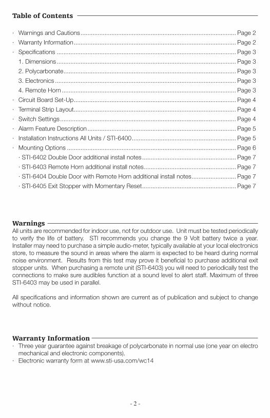
· Warnings and Cautions ........................................................................................... Page 2
· Warranty Information ............................................................................................... Page 2
· Specifications ......................................................................................................... Page 3
1. Dimensions ......................................................................................................... Page 3
2. Polycarbonate ..................................................................................................... Page 3
3. Electronics .......................................................................................................... Page 3
4. Remote Horn ...................................................................................................... Page 3
· Circuit Board Set-Up ............................................................................................... Page 4
· Terminal Strip Layout ............................................................................................... Page 4
· Switch Settings ....................................................................................................... Page 4
· Alarm Feature Description ....................................................................................... Page 5
· Installation Instructions All Units / STI-6400 ............................................................. Page 5
· Mounting Options ................................................................................................... Page 6
· STI-6402 Double Door additional install notes ....................................................... Page 7
· STI-6403 Remote Horn additional install notes ...................................................... Page 7
· STI-6404 Double Door with Remote Horn additional install notes .......................... Page 7
· STI-6405 Exit Stopper with Momentary Reset ....................................................... Page 7
WarningsAll units are recommended for indoor use, not for outdoor use. Unit must be tested periodically to verify the life of battery. STI recommends you change the 9 Volt battery twice a year. Installer may need to purchase a simple audio-meter, typically available at your local electronics store, to measure the sound in areas where the alarm is expected to be heard during normal noise environment. Results from this test may prove it beneficial to purchase additional exit stopper units. When purchasing a remote unit (STI-6403) you will need to periodically test the connections to make sure audibles function at a sound level to alert staff. Maximum of three STI-6403 may be used in parallel.
All specifications and information shown are current as of publication and subject to change without notice.
Warranty Information· Three year guarantee against breakage of polycarbonate in normal use (one year on electro
mechanical and electronic components).· Electronic warranty form at www.sti-usa.com/wc14
- 3 -
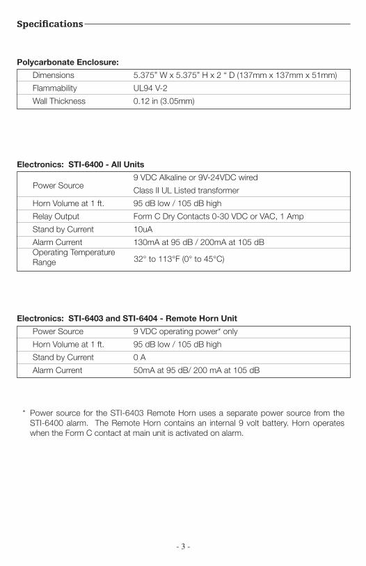
Specifications
Polycarbonate Enclosure:
Dimensions 5.375” W x 5.375” H x 2 “ D (137mm x 137mm x 51mm)
Flammability UL94 V-2
Wall Thickness 0.12 in (3.05mm)
Electronics: STI-6403 and STI-6404 - Remote Horn Unit
Power Source 9 VDC operating power* only
Horn Volume at 1 ft. 95 dB low / 105 dB high
Stand by Current 0 A
Alarm Current 50mA at 95 dB/ 200 mA at 105 dB
* Power source for the STI-6403 Remote Horn uses a separate power source from the STI-6400 alarm. The Remote Horn contains an internal 9 volt battery. Horn operates when the Form C contact at main unit is activated on alarm.
Electronics: STI-6400 - All Units
9 VDC Alkaline or 9V-24VDC wired
Class II UL Listed transformer
Horn Volume at 1 ft. 95 dB low / 105 dB high
Relay Output Form C Dry Contacts 0-30 VDC or VAC, 1 Amp
Stand by Current 10uA
Alarm Current 130mA at 95 dB / 200mA at 105 dB Operating Temperature Range
Power Source
32° to 113°F (0° to 45°C)
- 4 -
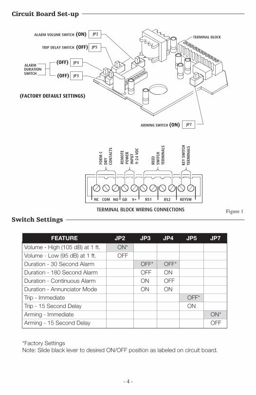
Circuit Board Set-up
Figure 1TERMINAL BLOCK(SEE BELOW)
FOR COMPLETE ALARM OPTIONSAND SWITCH SETTINGS SEE CHART
ON REVERSE SIDE.
PC BOARD
JP5
JP2
JP4
JP3
JP7
SWITCH
ALARMDURATION
ALARM VOLUME SWITCH
TRIP DELAY SWITCH
ARMING SWITCH
)( FACTORY DEFAULT SETTINGS
(FACTORY DEFAULT SETTINGS)
(ON)
(ON)
(OFF)
(OFF)
(OFF)
TERMINAL BLOCK
FOR COMPLETE ALARM OPTIONSAND SWITCH SETTINGS SEE CHART
ON REVERSE SIDE.
PC BOARD
JP5
JP2
JP4
JP3
JP7
SWITCH
ALARMDURATION
ALARM VOLUME SWITCH
TRIP DELAY SWITCH
ARMING SWITCH
)( FACTORY DEFAULT SETTINGS
(FACTORY DEFAULT SETTINGS)
(ON)
(ON)
(OFF)
(OFF)
(OFF)
Switch Settings
Volume - High (105 dB) at 1 ft. ON*Volume - Low (95 dB) at 1 ft. OFFDuration - 30 Second Alarm OFF* OFF*Duration - 180 Second Alarm OFF ONDuration - Continuous Alarm ON OFFDuration - Annunciator Mode ON ONTrip - Immediate OFF*Trip - 15 Second Delay ONArming - Immediate ON*Arming - 15 Second Delay OFF
FEATURE JP2 JP3 JP4 JP5 JP7
*Factory SettingsNote: Slide black lever to desired ON/OFF position as labeled on circuit board.
POLYCARBONATE COVER
POLYCARBONATE BASE
120 dB HORN
ALARM DURATION
ALARM TRIP DELAY
EXIT DELAYVOLUME
VIEW OF THE CIRCUIT BOARD
19039 SCREW6 x 1 1/4 in.
(2) PROVIDED
19018 ANCHOR(2) PROVIDED
BOTTOM SURFACE AS SHOWNWIRES THROUGH NOTCH ONAND ROUTE REED SWITCHREMOVE FRONT COVER
VIEW SHOWING MAGNET INSTALLATION
MAGNET
NC COM NO GD V+ RS1 RS2 KEYSW
TERMINAL BLOCK WIRING CONNECTIONS
FORM
CD
RYCO
NTA
CTS
REM
OTE
PO
WER
INPU
T9-
24 V
DC
REED
SWIT
CHTE
RMIN
ALS
KEY
SWIT
CHTE
RMIN
ALS
INTERNAL REED SWITCH(RS1)
ALARM DURATION
ALARM TRIP DELAY
EXIT DELAYVOLUME
VIEW OF THE CIRCUIT BOARD
MAXIMUM GAP 3/4 in. (19mm) 3/8 in. (9.5mm) ON METAL DOORAND FRAME
SPACERS (USE AS NECESSARY)NOTE: 2 SPACERS UNDER BOTHMAGNET AND REED SWITCHMUST BE USED ON STEEL DOORS
4
3
2
1
NCCOMNOGDV+RS1RS2KEYSW
SLOTSFLANGES
TERMINAL STRIP
9 VOLT BATTERY
19011 TAMPERPROOF SCREW(1) PROVIDED
19016 TAMPER WRENCH(1) PROVIDED
BASE
19014 MOUNTING SCREW(4) PROVIDED
REED SWITCHMOUNTING LOCATIONS
(LABELED 1-4)
COVER
NCCOMNOGDV+RS1RS2KEYSW
4
3
2
1
NCCOMNOGDV+RS1RS2KEYSW
SLOTSFLANGES
TERMINAL STRIP
9 VOLT BATTERY
19011 TAMPERPROOF SCREW(1) PROVIDED
19016 TAMPER WRENCH(1) PROVIDEDBASE
19014 MOUNTING SCREW(4) PROVIDED
REED SWITCHMOUNTING LOCATIONS
(LABELED 1-4)
COVER
4
3
2
1
ALARM SOUNDS WHEN DOOR IS OPENED
EMERGENCY USE ONLY
ON OFF
NCCOMNOGDV+RS1RS2KEYSW
SLOTS
FLANGES
TERMINAL STRIP9 VOLT BATTERY
19011 TAMPERPROOF SCREW(1) PROVIDED
19016 TAMPER WRENCH(1) PROVIDEDBASE
19014 MOUNTING SCREW(4) PROVIDED
REED SWITCHMOUNTING LOCATIONS
(LABELED 1-4)
COVER
TO KEYSWITCH
06402 REED SWITCH(RS2)
OPTIONAL:TO REMOTE
HORNSTI-6403
TERMINAL BLOCK
VIEW SHOWING INSTALLATION OFADDTIONAL REED SWITCH 06402
3/4 in. (19mm)MAXIMUM GAP3/8 in. (9.5mm) ONMETAL DOOR AND FRAME
MAGNET ASSEMBLY(SEE ABOVE FOR INSTALLATION)
DOORSWING
6400 SWING
MAGNET
DOOR STOP
MAGNET MUST BEINSTALLED OPPOSITERAISED RIB ON OUTER COVER
19039 SCREW6 x 1 1/4 in.(2) PROVIDED
SPACERS - USEAS NECESSARY
NOTE: (2) SPACERS MUST BEUSED ON STEEL DOORS
19018 ANCHOR(2) PROVIDED
MAGNET
6400 UNIT
DOORSWING
JAM
DOOR STOP
DOOR
TYPICAL FLUSH MOUNT DOOR JAMINSTALLATION
TYPICAL RECESSED MOUNT DOOR JAMINSTALLATION
- 5 -
Alarm Feature Description
· Volume Switch JP2 - Sets alarm volume to high 105 dB or low 95 dB. · Duration Switch JP3 and JP4 - Amount of time alarm sounds after trip. Arming resets at
end of duration if door is closed. Alarm will not reset if in continuous mode; alarm sounds until battery is drained. Annunciator Mode is a series of 10 short beeps or until door is closed.
· Trip Delay Switch JP5 - If you wish to ENTER an alarmed door without sounding the horn immediately, the trip delay will allow 15 seconds for you to enter and de-activate the alarm with the key switch before the alarm will sound.
· Arming Switch JP7 - This mode is useful when an AUTHORIZED EXIT is required through alarmed door. In “ON” position immediate arming will set the alarm ready to function as soon as door is opened. In “OFF” position delay arming will allow 15 seconds for you to exit through the door without sending alarm signal.
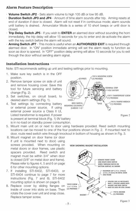
Installation Instructions
1. Make sure key switch is in the OFF position.
2. Remove tamper screw on side of unit and remove housing cover. Save this tool for future servicing and battery change (Fig. 2).
3. Set switches, on circuit board, to desired alarm settings (Fig. 1).
4. Test settings by connecting battery or external power source. If using external power source a Class II UL Listed transformer is required. If power is present at terminal block (Fig. 1) 9V battery is in no-load on standby power consumption.
5. Mount main unit on or next to door using hardware provided. Reed switch mounting locations can be moved to one of the four positions shown in Fig. 2. If mounted next to door, route reed switch wire through knockout in bottom of housing as shown in Fig. 3.
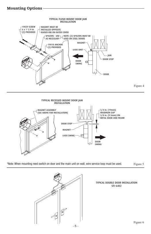
6. Mount magnet on door frame (or door if unit is mounted next to door) using screws provided. When mounting on metal doors or door frames, use plastic spacers provided. Reed switch and magnet must be within 3/4” when door is closed (3/8” on metal door and frame). Please refer to figures 4, 5 and 6 on page 6 for other mounting options.
7. If installing STI-6402, STI-6403, or STI-6404 continue to page 7 for more instructions (Fig. 7 and 8). STI-6402 mounting option is shown on page 6.
8. Replace cover by sliding flanges on inside of cover into slots on base. Then rotate the cover over unit and snap close. Replace tamper screw.
Note: STI recommends setting up unit and testing settings prior to mounting.
Figure 3
POLYCARBONATE COVER
POLYCARBONATE BASE
120 dB HORN
ALARM DURATION
ALARM TRIP DELAY
EXIT DELAYVOLUME
VIEW OF THE CIRCUIT BOARD
19039 SCREW6 x 1 1/4 in.
(2) PROVIDED
19018 ANCHOR(2) PROVIDED
BOTTOM SURFACE AS SHOWNWIRES THROUGH NOTCH ONAND ROUTE REED SWITCHREMOVE FRONT COVER
VIEW SHOWING MAGNET INSTALLATION
MAGNET
NC COM NO GD V+ RS1 RS2 KEYSW
TERMINAL BLOCK WIRING CONNECTIONS
FORM
CD
RYCO
NTA
CTS
REM
OTE
PO
WER
INPU
T9-
24 V
DC
REED
SWIT
CHTE
RMIN
ALS
KEY
SWIT
CHTE
RM
INA
LS
INTERNAL REED SWITCH(RS1)
ALARM DURATION
ALARM TRIP DELAY
EXIT DELAYVOLUME
VIEW OF THE CIRCUIT BOARD
MAXIMUM GAP 3/4 in. (19mm) 3/8 in. (9.5mm) ON METAL DOORAND FRAME
SPACERS (USE AS NECESSARY)NOTE: 2 SPACERS UNDER BOTHMAGNET AND REED SWITCHMUST BE USED ON STEEL DOORS
4
3
2
1
NCCOMNOGDV+RS1RS2KEYSW
SLOTSFLANGES
TERMINAL STRIP
9 VOLT BATTERY
19011 TAMPERPROOF SCREW(1) PROVIDED
19016 TAMPER WRENCH(1) PROVIDED
BASE
19014 MOUNTING SCREW(4) PROVIDED
REED SWITCHMOUNTING LOCATIONS
(LABELED 1-4)
COVER
NCCOMNOGDV+RS1RS2KEYSW
4
3
2
1
NCCOMNOGDV+RS1RS2KEYSW
SLOTSFLANGES
TERMINAL STRIP
9 VOLT BATTERY
19011 TAMPERPROOF SCREW(1) PROVIDED
19016 TAMPER WRENCH(1) PROVIDEDBASE
19014 MOUNTING SCREW(4) PROVIDED
REED SWITCHMOUNTING LOCATIONS
(LABELED 1-4)
COVER
4
3
2
1
ALARM SOUNDS WHEN DOOR IS OPENED
EMERGENCY USE ONLY
ON OFF
NCCOMNOGDV+RS1RS2KEYSW
SLOTS
FLANGES
TERMINAL STRIP9 VOLT BATTERY
19011 TAMPERPROOF SCREW(1) PROVIDED
19016 TAMPER WRENCH(1) PROVIDEDBASE
19014 MOUNTING SCREW(4) PROVIDED
REED SWITCHMOUNTING LOCATIONS
(LABELED 1-4)
COVER
TO KEYSWITCH
06402 REED SWITCH(RS2)
OPTIONAL:TO REMOTE
HORNSTI-6403
TERMINAL BLOCK
VIEW SHOWING INSTALLATION OFADDTIONAL REED SWITCH 06402
3/4 in. (19mm)MAXIMUM GAP3/8 in. (9.5mm) ONMETAL DOOR AND FRAME
MAGNET ASSEMBLY(SEE ABOVE FOR INSTALLATION)
DOORSWING
6400 SWING
MAGNET
DOOR STOP
MAGNET MUST BEINSTALLED OPPOSITERAISED RIB ON OUTER COVER
19039 SCREW6 x 1 1/4 in.(2) PROVIDED
SPACERS - USEAS NECESSARY
NOTE: (2) SPACERS MUST BEUSED ON STEEL DOORS
19018 ANCHOR(2) PROVIDED
MAGNET
6400 UNIT
DOORSWING
JAM
DOOR STOP
DOOR
TYPICAL FLUSH MOUNT DOOR JAMINSTALLATION
TYPICAL RECESSED MOUNT DOOR JAMINSTALLATION
POLYCARBONATE COVER
POLYCARBONATE BASE
120 dB HORN
ALARM DURATION
ALARM TRIP DELAY
EXIT DELAYVOLUME
VIEW OF THE CIRCUIT BOARD
19039 SCREW6 x 1 1/4 in.
(2) PROVIDED
19018 ANCHOR(2) PROVIDED
BOTTOM SURFACE AS SHOWNWIRES THROUGH NOTCH ONAND ROUTE REED SWITCHREMOVE FRONT COVER
VIEW SHOWING MAGNET INSTALLATION
MAGNET
NC COM NO GD V+ RS1 RS2 KEYSW
TERMINAL BLOCK WIRING CONNECTIONS
FORM
CD
RYCO
NTA
CTS
REM
OTE
PO
WER
INPU
T9-
24 V
DC
REED
SWIT
CHTE
RMIN
ALS
KEY
SWIT
CHTE
RMIN
ALS
INTERNAL REED SWITCH(RS1)
ALARM DURATION
ALARM TRIP DELAY
EXIT DELAYVOLUME
VIEW OF THE CIRCUIT BOARD
MAXIMUM GAP 3/4 in. (19mm) 3/8 in. (9.5mm) ON METAL DOORAND FRAME
SPACERS (USE AS NECESSARY)NOTE: 2 SPACERS UNDER BOTHMAGNET AND REED SWITCHMUST BE USED ON STEEL DOORS
4
3
2
1
NCCOMNOGDV+RS1RS2KEYSW
SLOTSFLANGES
TERMINAL STRIP
9 VOLT BATTERY
19011 TAMPERPROOF SCREW(1) PROVIDED
19016 TAMPER WRENCH(1) PROVIDED
BASE
19014 MOUNTING SCREW(4) PROVIDED
REED SWITCHMOUNTING LOCATIONS
(LABELED 1-4)
COVER
NCCOMNOGDV+RS1RS2KEYSW
4
3
2
1
NCCOMNOGDV+RS1RS2KEYSW
SLOTSFLANGES
TERMINAL STRIP
9 VOLT BATTERY
19011 TAMPERPROOF SCREW(1) PROVIDED
19016 TAMPER WRENCH(1) PROVIDEDBASE
19014 MOUNTING SCREW(4) PROVIDED
REED SWITCHMOUNTING LOCATIONS
(LABELED 1-4)
COVER
4
3
2
1
ALARM SOUNDS WHEN DOOR IS OPENED
EMERGENCY USE ONLY
ON OFF
NCCOMNOGDV+RS1RS2KEYSW
SLOTS
FLANGES
TERMINAL STRIP9 VOLT BATTERY
19011 TAMPERPROOF SCREW(1) PROVIDED
19016 TAMPER WRENCH(1) PROVIDEDBASE
19014 MOUNTING SCREW(4) PROVIDED
REED SWITCHMOUNTING LOCATIONS
(LABELED 1-4)
COVER
TO KEYSWITCH
06402 REED SWITCH(RS2)
OPTIONAL:TO REMOTE
HORNSTI-6403
TERMINAL BLOCK
VIEW SHOWING INSTALLATION OFADDTIONAL REED SWITCH 06402
3/4 in. (19mm)MAXIMUM GAP3/8 in. (9.5mm) ONMETAL DOOR AND FRAME
MAGNET ASSEMBLY(SEE ABOVE FOR INSTALLATION)
DOORSWING
6400 SWING
MAGNET
DOOR STOP
MAGNET MUST BEINSTALLED OPPOSITERAISED RIB ON OUTER COVER
19039 SCREW6 x 1 1/4 in.(2) PROVIDED
SPACERS - USEAS NECESSARY
NOTE: (2) SPACERS MUST BEUSED ON STEEL DOORS
19018 ANCHOR(2) PROVIDED
MAGNET
6400 UNIT
DOORSWING
JAM
DOOR STOP
DOOR
TYPICAL FLUSH MOUNT DOOR JAMINSTALLATION
TYPICAL RECESSED MOUNT DOOR JAMINSTALLATION
Figure 2
- 6 -
Mounting Options
TYPICAL DOUBLE DOOR INSTALLATION
STI 6402
*Note: When mounting reed switch on door and the main unit on wall, wire service loop must be used.
TYPICAL DOUBLE DOOR INSTALLATIONSTI-6402
Figure 4
Figure 5
Figure 6
POLYCARBONATE COVER
POLYCARBONATE BASE
120 dB HORN
ALARM DURATION
ALARM TRIP DELAY
EXIT DELAYVOLUME
VIEW OF THE CIRCUIT BOARD
19039 SCREW6 x 1 1/4 in.
(2) PROVIDED
19018 ANCHOR(2) PROVIDED
BOTTOM SURFACE AS SHOWNWIRES THROUGH NOTCH ONAND ROUTE REED SWITCHREMOVE FRONT COVER
VIEW SHOWING MAGNET INSTALLATION
MAGNET
NC COM NO GD V+ RS1 RS2 KEYSW
TERMINAL BLOCK WIRING CONNECTIONS
FORM
CD
RYCO
NTA
CTS
REM
OTE
PO
WER
INPU
T9-
24 V
DC
REED
SWIT
CHTE
RMIN
ALS
KEY
SWIT
CHTE
RMIN
ALS
INTERNAL REED SWITCH(RS1)
ALARM DURATION
ALARM TRIP DELAY
EXIT DELAYVOLUME
VIEW OF THE CIRCUIT BOARD
MAXIMUM GAP 3/4 in. (19mm) 3/8 in. (9.5mm) ON METAL DOORAND FRAME
SPACERS (USE AS NECESSARY)NOTE: 2 SPACERS UNDER BOTHMAGNET AND REED SWITCHMUST BE USED ON STEEL DOORS
4
3
2
1
NCCOMNOGDV+RS1RS2KEYSW
SLOTSFLANGES
TERMINAL STRIP
9 VOLT BATTERY
19011 TAMPERPROOF SCREW(1) PROVIDED
19016 TAMPER WRENCH(1) PROVIDED
BASE
19014 MOUNTING SCREW(4) PROVIDED
REED SWITCHMOUNTING LOCATIONS
(LABELED 1-4)
COVER
NCCOMNOGDV+RS1RS2KEYSW
4
3
2
1
NCCOMNOGDV+RS1RS2KEYSW
SLOTSFLANGES
TERMINAL STRIP
9 VOLT BATTERY
19011 TAMPERPROOF SCREW(1) PROVIDED
19016 TAMPER WRENCH(1) PROVIDEDBASE
19014 MOUNTING SCREW(4) PROVIDED
REED SWITCHMOUNTING LOCATIONS
(LABELED 1-4)
COVER
4
3
2
1
ALARM SOUNDS WHEN DOOR IS OPENED
EMERGENCY USE ONLY
ON OFF
NCCOMNOGDV+RS1RS2KEYSW
SLOTS
FLANGES
TERMINAL STRIP9 VOLT BATTERY
19011 TAMPERPROOF SCREW(1) PROVIDED
19016 TAMPER WRENCH(1) PROVIDEDBASE
19014 MOUNTING SCREW(4) PROVIDED
REED SWITCHMOUNTING LOCATIONS
(LABELED 1-4)
COVER
TO KEYSWITCH
06402 REED SWITCH(RS2)
OPTIONAL:TO REMOTE
HORNSTI-6403
TERMINAL BLOCK
VIEW SHOWING INSTALLATION OFADDTIONAL REED SWITCH 06402
3/4 in. (19mm)MAXIMUM GAP3/8 in. (9.5mm) ONMETAL DOOR AND FRAME
MAGNET ASSEMBLY(SEE ABOVE FOR INSTALLATION)
DOORSWING
6400 SWING
MAGNET
DOOR STOP
MAGNET MUST BEINSTALLED OPPOSITERAISED RIB ON OUTER COVER
19039 SCREW6 x 1 1/4 in.(2) PROVIDED
SPACERS - USEAS NECESSARY
NOTE: (2) SPACERS MUST BEUSED ON STEEL DOORS
19018 ANCHOR(2) PROVIDED
MAGNET
6400 UNIT
DOORSWING
JAM
DOOR STOP
DOOR
TYPICAL FLUSH MOUNT DOOR JAMINSTALLATION
TYPICAL RECESSED MOUNT DOOR JAMINSTALLATION
POLYCARBONATE COVER
POLYCARBONATE BASE
120 dB HORN
ALARM DURATION
ALARM TRIP DELAY
EXIT DELAYVOLUME
VIEW OF THE CIRCUIT BOARD
19039 SCREW6 x 1 1/4 in.
(2) PROVIDED
19018 ANCHOR(2) PROVIDED
BOTTOM SURFACE AS SHOWNWIRES THROUGH NOTCH ONAND ROUTE REED SWITCHREMOVE FRONT COVER
VIEW SHOWING MAGNET INSTALLATION
MAGNET
NC COM NO GD V+ RS1 RS2 KEYSW
TERMINAL BLOCK WIRING CONNECTIONS
FORM
CD
RYCO
NTA
CTS
REM
OTE
PO
WER
INPU
T9-
24 V
DC
REED
SWIT
CHTE
RMIN
ALS
KEY
SWIT
CHTE
RMIN
ALS
INTERNAL REED SWITCH(RS1)
ALARM DURATION
ALARM TRIP DELAY
EXIT DELAYVOLUME
VIEW OF THE CIRCUIT BOARD
MAXIMUM GAP 3/4 in. (19mm) 3/8 in. (9.5mm) ON METAL DOORAND FRAME
SPACERS (USE AS NECESSARY)NOTE: 2 SPACERS UNDER BOTHMAGNET AND REED SWITCHMUST BE USED ON STEEL DOORS
4
3
2
1
NCCOMNOGDV+RS1RS2KEYSW
SLOTSFLANGES
TERMINAL STRIP
9 VOLT BATTERY
19011 TAMPERPROOF SCREW(1) PROVIDED
19016 TAMPER WRENCH(1) PROVIDED
BASE
19014 MOUNTING SCREW(4) PROVIDED
REED SWITCHMOUNTING LOCATIONS
(LABELED 1-4)
COVER
NCCOMNOGDV+RS1RS2KEYSW
4
3
2
1
NCCOMNOGDV+RS1RS2KEYSWSLOTS
FLANGES
TERMINAL STRIP
9 VOLT BATTERY
19011 TAMPERPROOF SCREW(1) PROVIDED
19016 TAMPER WRENCH(1) PROVIDEDBASE
19014 MOUNTING SCREW(4) PROVIDED
REED SWITCHMOUNTING LOCATIONS
(LABELED 1-4)
COVER
4
3
2
1
ALARM SOUNDS WHEN DOOR IS OPENED
EMERGENCY USE ONLY
ON OFF
NCCOMNOGDV+RS1RS2KEYSW
SLOTS
FLANGES
TERMINAL STRIP9 VOLT BATTERY
19011 TAMPERPROOF SCREW(1) PROVIDED
19016 TAMPER WRENCH(1) PROVIDEDBASE
19014 MOUNTING SCREW(4) PROVIDED
REED SWITCHMOUNTING LOCATIONS
(LABELED 1-4)
COVER
TO KEYSWITCH
06402 REED SWITCH(RS2)
OPTIONAL:TO REMOTE
HORNSTI-6403
TERMINAL BLOCK
VIEW SHOWING INSTALLATION OFADDTIONAL REED SWITCH 06402
3/4 in. (19mm)MAXIMUM GAP3/8 in. (9.5mm) ONMETAL DOOR AND FRAME
MAGNET ASSEMBLY(SEE ABOVE FOR INSTALLATION)
DOORSWING
6400 SWING
MAGNET
DOOR STOP
MAGNET MUST BEINSTALLED OPPOSITERAISED RIB ON OUTER COVER
19039 SCREW6 x 1 1/4 in.(2) PROVIDED
SPACERS - USEAS NECESSARY
NOTE: (2) SPACERS MUST BEUSED ON STEEL DOORS
19018 ANCHOR(2) PROVIDED
MAGNET
6400 UNIT
DOORSWING
JAM
DOOR STOP
DOOR
TYPICAL FLUSH MOUNT DOOR JAMINSTALLATION
TYPICAL RECESSED MOUNT DOOR JAMINSTALLATION
- 7 -
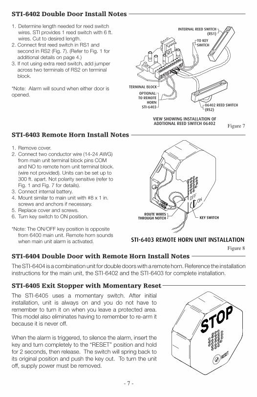
STI-6402 Double Door Install Notes
1. Determine length needed for reed switch wires. STI provides 1 reed switch with 6 ft. wires. Cut to desired length.
2. Connect first reed switch in RS1 and second in RS2 (Fig. 7). (Refer to Fig. 1 for additional details on page 4.)
3. If not using extra reed switch, add jumper across two terminals of RS2 on terminal block.
*Note: Alarm will sound when either door is opened.
STI-6403 Remote Horn Install Notes
NOTE: WIRING NOT PROVIDED
NOTE: 14-24 AWG MAY BE USED.
B
EXISTING
EXISTING
TO STI 6400 CIRCUITBOARD TERMINAL STRIP.
VIEW IN DIRECTION OF ARROW
REMOTE HORN WIRE CONNECTIONS
STI-6403 REMOTE HORN UNIT INSTALLATION
B
ROUTE WIRESTHROUGH NOTCH KEY SWITCH
1. Remove cover.2. Connect two conductor wire (14-24 AWG)
from main unit terminal block pins COM and NO to remote horn unit terminal block. (wire not provided). Units can be set up to 300 ft. apart. Not polarity sensitive (refer to Fig. 1 and Fig. 7 for details).
3. Connect internal battery.4. Mount similar to main unit with #8 x 1 in.
screws and anchors if necessary.5. Replace cover and screws.6. Turn key switch to ON position.
*Note: The ON/OFF key position is opposite from 6400 main unit. Remote horn sounds when main unit alarm is activated.
STI-6404 Double Door with Remote Horn Install Notes
The STI-6404 is a combination unit for double doors with a remote horn. Reference the installation instructions for the main unit, the STI-6402 and the STI-6403 for complete installation.
STI-6405 Exit Stopper with Momentary Reset
The STI-6405 uses a momentary switch. After initial installation, unit is always on and you do not have to remember to turn it on when you leave a protected area. This model also eliminates having to remember to re-arm it because it is never off.
When the alarm is triggered, to silence the alarm, insert the key and turn completely to the “RESET” position and hold for 2 seconds, then release. The switch will spring back to its original position and push the key out. To turn the unit off, supply power must be removed.
RESET
Figure 7
Figure 8
POLYCARBONATE COVER
POLYCARBONATE BASE
120 dB HORN
ALARM DURATION
ALARM TRIP DELAY
EXIT DELAYVOLUME
VIEW OF THE CIRCUIT BOARD
19039 SCREW6 x 1 1/4 in.
(2) PROVIDED
19018 ANCHOR(2) PROVIDED
BOTTOM SURFACE AS SHOWNWIRES THROUGH NOTCH ONAND ROUTE REED SWITCHREMOVE FRONT COVER
VIEW SHOWING MAGNET INSTALLATION
MAGNET
NC COM NO GD V+ RS1 RS2 KEYSW
TERMINAL BLOCK WIRING CONNECTIONS
FORM
CD
RYCO
NTA
CTS
REM
OTE
PO
WER
INPU
T9-
24 V
DC
REE
DSW
ITCH
TER
MIN
ALS
KEY
SWIT
CHTE
RM
INA
LS
INTERNAL REED SWITCH(RS1)
ALARM DURATION
ALARM TRIP DELAY
EXIT DELAYVOLUME
VIEW OF THE CIRCUIT BOARD
MAXIMUM GAP 3/4 in. (19mm) 3/8 in. (9.5mm) ON METAL DOORAND FRAME
SPACERS (USE AS NECESSARY)NOTE: 2 SPACERS UNDER BOTHMAGNET AND REED SWITCHMUST BE USED ON STEEL DOORS
4
3
2
1
NCCOMNOGDV+RS1RS2KEYSW
SLOTSFLANGES
TERMINAL STRIP
9 VOLT BATTERY
19011 TAMPERPROOF SCREW(1) PROVIDED
19016 TAMPER WRENCH(1) PROVIDED
BASE
19014 MOUNTING SCREW(4) PROVIDED
REED SWITCHMOUNTING LOCATIONS
(LABELED 1-4)
COVER
NCCOMNOGDV+RS1RS2KEYSW
4
3
2
1
NCCOMNOGDV+RS1RS2KEYSW
SLOTSFLANGES
TERMINAL STRIP
9 VOLT BATTERY
19011 TAMPERPROOF SCREW(1) PROVIDED
19016 TAMPER WRENCH(1) PROVIDEDBASE
19014 MOUNTING SCREW(4) PROVIDED
REED SWITCHMOUNTING LOCATIONS
(LABELED 1-4)
COVER
4
3
2
1
ALARM SOUNDS WHEN DOOR IS OPENED
EMERGENCY USE ONLY
ON OFF
NCCOMNOGDV+RS1RS2KEYSW
SLOTS
FLANGES
TERMINAL STRIP9 VOLT BATTERY
19011 TAMPERPROOF SCREW(1) PROVIDED
19016 TAMPER WRENCH(1) PROVIDEDBASE
19014 MOUNTING SCREW(4) PROVIDED
REED SWITCHMOUNTING LOCATIONS
(LABELED 1-4)
COVER
TO KEYSWITCH
06402 REED SWITCH(RS2)
OPTIONAL:TO REMOTE
HORNSTI-6403
TERMINAL BLOCK
VIEW SHOWING INSTALLATION OFADDTIONAL REED SWITCH 06402
3/4 in. (19mm)MAXIMUM GAP3/8 in. (9.5mm) ONMETAL DOOR AND FRAME
MAGNET ASSEMBLY(SEE ABOVE FOR INSTALLATION)
DOORSWING
6400 SWING
MAGNET
DOOR STOP
MAGNET MUST BEINSTALLED OPPOSITERAISED RIB ON OUTER COVER
19039 SCREW6 x 1 1/4 in.(2) PROVIDED
SPACERS - USEAS NECESSARY
NOTE: (2) SPACERS MUST BEUSED ON STEEL DOORS
19018 ANCHOR(2) PROVIDED
MAGNET
6400 UNIT
DOORSWING
JAM
DOOR STOP
DOOR
TYPICAL FLUSH MOUNT DOOR JAMINSTALLATION
TYPICAL RECESSED MOUNT DOOR JAMINSTALLATION

- 8 -
Inst. 6400 JAN2014Printed in USA Subject to change without notice.
2306 Airport Rd • Waterford, MI 48327Phone: 248-673-9898 • Fax: 248-673-1246
[email protected] • www.sti-usa.com
Safety Technology International (Europe) Ltd.Unit 49G Pipers Road • Park Farm Industrial Estate • RedditchWorcestershire • B98 0HU • England • Tel: 44 (0) 1527 520 999Fax: 44 (0) 1527 501 999 • Freephone: 0800 085 1678 (UK only)
E-mail: [email protected] • Web: www.sti-europe.com