Exhibit - PRWebww1.prweb.com/prfiles/2016/08/18/13626748/ESPRO Inc Complaint 16-cv... · Exhibit...
20
Exhibit Case 1:16-cv-04115-BMC Document 8 Filed 08/16/16 Page 35 of 93 PageID #: 107
-
Upload
trinhkhanh -
Category
Documents
-
view
213 -
download
0
Transcript of Exhibit - PRWebww1.prweb.com/prfiles/2016/08/18/13626748/ESPRO Inc Complaint 16-cv... · Exhibit...

Exhibit
Case 1:16-cv-04115-BMC Document 8 Filed 08/16/16 Page 35 of 93 PageID #: 107

IIl IlI IlO
1101
I0 II0 IIi l0 III I0
Il0I
Il 0I Il
US009408490B2
12 United States Patent
McLean et
10 Patent No45 Date of Patent
Us 9408490 B2
Aug 2016
54 APPARATUS AND METHOD FOR 56EXTRACTING AN INFUSION
71 Applicant ES PRO INC Vancouver CA
72 Inventors Christopher McLean Vancouver
CA Bruce Constantine North
Attleboro MA US
73 Assignee ESPRO INC Vancouver CA
Notice Subject to any disclaimer thc term of this
patent is extended or adjusted under 35
U.S.C 154b by days
21 AppI No 14/318371
22 Filed Jun 27 2014
65 Prior Publication Data
US 2014/0311353 Al Oct 23 2014
Related U.S Application Data
62 Division of application No 12/991425 filed as
application No PCT/CA2009/000604 on May 122009 now Pat No 8.770.097
60 Provisional application No 1/127430 filed on May12 2008
51 mt ClA47.J 31/38 2006.01
A47J31/20 2006.01
BOlD 11/02 2006.01
52 U.S CI
CPC A47J31/38 2013.01 A47J31/20 2013.01BOlD 11/0253 2013.01
58 Field of Classification Search
CPC A47J31/20 A47J31/38 BOlD 11/0253
USPC ............ D7/400 510 99/279 287 297 322
99/323 426/80 433 435
See application file for complete search history
International Preliminary Repost on Patentability issued Nov t7
2010 and International Sesrch Report issued Aug 2009 for
related application PCT/CA2009/000604 and pages
Continued
Primary Examiner Thien Tran
74 Attorney Agent or Firm Day Pitney l.1P
57 ABSTRACT
An infusion extractor is provided including plunger to be
inserted into an intissing container containing the intusson
mixture that has vertical inner walls oriented parallel to
vertical axis of the container The plunger includes first
surface with seal situated at an edge of the surface The seal
is adapted fur sealing against the inner walls of the infi.ssing
container as the plunger moves within the container to define
first chamber containing the mixture of infusible material
and extract The plunger also includes second surface
extending frnm the first surface mid defining second cham
ber the second surface includes extract flow openings which
permit flow of extract from the first chamber into the second
chamber At least portion of the extract flow openings are
situated at depth either above or below the first surface along
the vertical axis
References Cited
U.S PATENT DOCUMENTS
1025206 5/19t2 Rounds
1581877 4/1926 Schultz
Continued
FOREIGN PATENT DOCUMENTS
t0t925t Al 10/1977
241874t At 8/2004
Continued
OTHER Pt JBLICATIONS
CACA
23 Claims 11 Drawing Sheets
Case 1:16-cv-04115-BMC Document 8 Filed 08/16/16 Page 36 of 93 PageID #: 108

US 9408490 B2
Page
56 References Cited 7194951 Bl 3/2007 Porter
D542078 5/2007 Bodum
U.S PATENT DOCUMENTs 7213507 B2 5i2007 Glucksman et al
D563713 3/2008 Bodsun
1954064 4/1934 B1i17 D565887 4/2008 Bodum
2299918 10/1942 MollenkampD566454 4/2008 Bodum
2468661 4/1949 Gladstone D571610 6/2008 Bodum
2516703 7/1950 Kent 7384182 B2 6/2008 Bhaynani
2592485 4/1952 Stair D573396 7/2008 Gauss
2793790 5/1957 KslilerD584559 1/2009 Bodum
3158084 11/1964 Cohn D587069 2/2009 Borlusn
3260510 7/1966 Ranson D594267 6/2009 Bodum
3561888 2/1971 Jordan 417/209 7578231 B2 8/2009 iu
3589683 6/1971 Robin D610860 3/2010 Bodusn
3657993 4/1972 Close D622546 8/2010 Bodusn
3927608 12/1975 Doyel D628846 12/2010 Bodum
3935318 1/1976 Mihailide 7858133 B2 12/2010 Noaco Jt etal
4066722 1/1978 Pietruszewski et al 7882975 B2 2/2011 Kelly
4602558 7/1986 Kaper et al 7946752 B2 5/2011 Swartz et al
4645132 2/1987 Pregnan 7958816 B2 6/2011 Lin
4650583 3/1987 Bondnnini 7992486 B2 8/2011 Constsnlineetal
4804550 2/1989 BardsleyetalD645290 9/2011 Bodum
4852474 8/1989 Malich et al 8051766 Bt 11/2011 Yu et al
4945824 8/1990 BorgmsnnD652682 1/2012 Eyal
4950082 8/1990 Carlson D653492 2/2012 Enghard
5106239 4/1992 Krebsbach D654756 2/2012 Bodsun
5141134 8/1992 Machado D655134 3/2012 Gilbert
5174194 12/1992 Pisna D655967 3/2012 Bodum
D348590 7/1994 Scott8152361 B2 4/2012 Swarta et al
5335588 8/1994 MsblielsD662354 6/2012 Bodum
5464574 11/1995 Mshlicls D663155 7/2012 l3odurn
5472274 12/1995 Baillie 8272532 B2 9/2012 Michaelian et al
5478586 12/1995 Connoi 8313644 B2 11/2012 Harris et al
5.487.486 1/1996 Meneo D677103 32013 Melzer
5526733 6/1996 Klawuhnetal 8387820 B2 3/2013 Park
D375233 11/1996 Hirsch D681388 5/2013 Hodum
5618570 4/1997 Banks el al 8448810 B2 5/2013 Kelly et al
5622099 4/1997 Prei 8529119 B2 9/2013 Swsrtz et 51
5636563 6/1997 Oppermaon et al D694579 12/2013 Khubani
5638740 6/1997 Cai D695138 12/2013 Ball
D384539 10/1997 Joergensen D698649 2/2014 Quint5770074 6/1998 Pugh D700807 3/2014 Kershawetal
5788369 8/1998 Tseng D701425 3/2014 Pearson
D401466 11/1998 Joergensen 8667662 B2 3/2014 KellyD405642 2/1999 Toriba
5887510 3/1999 Porter8695486 H2 4/2014 Hodsun
D410170 5/1999 Sheu8770097 H2 7/20 14 McLean et al
5911810 6/1999 Kawabata2001/0053399 Al 12/2001 Heiod
5913964 6/1999 Mellon 99/3222003/0047081 Al 3/2003 MeGonagle
503200R R/I009 Ross 210/3372003/0070979 Al 4/2003 Husng 210/469
D413480 9/1999 Joesgensen2003/0205145 Al 11/2003 Chang
6095032 8/2000 Barnett el 51 2004/02 06243 Al 10/2004 Poster el al
D435l95 12/2000 Joergensen2005/0046211 Al 3/2005 Nole et al
6220147 BI 4/2001 Priley2005/0109689 Al 5/2005 Trachtenbroit
D448601 10/2001 Yeh 2006/0118481 Al 6/2006 Trachtenbroil
D448602 10/2001 Hodum 2007/0028779 Al 2/2007 Pigliasneampo et al
D448603 10/2001 Yeh 2007/0151461 Al 7/2007 Edmark
D449760 10/2001 Yeh 2007/0187421 Al 8/2007 Conslsislineel al
6296884 HI 10/2001 Gkerlund 2007/0251956 Al 11/2007 Wasserman etal
D450223 11/2001 Joergenson 2008/004 1860 Al 2/2008 Wiedsneyer et al
6324966 HI 12/2001 Joergensen 2010/0263549 Al 10/2010 Lee
D453446 2/2002 Bodum2010/0294772 Al 11/2010 Judge
D457377 5/2002 Jorgensen 2010/03 19549 Al 12/2010 Kelly et al
6382083 H2 5/2002 Schmed
6412394 B2 7/2002 Bonanno2011/0056385 Al 3/2011 MeLcanetal
D462233 0/2002 Jorgensen2011/0309094 Al 122011 Bodum
D468597 1/2003 Kerr2012/0067890 Al 32012 Cahen et al
6736295 H2 5/2004 Lin et al20 12/0097042 Al 4/20 12 Lin
D493662 8/2004 Borlum 2012/0199160 Al 8/2012 Galbis
D494803 8/2004 Bodum 201210216682 Al 8/2012 Bodum
6797160 H2 9/2004 Huang 2012/0328750 Al 12/2012 Giordano
6797304 H2 9/2004 MeGonagle 20 13/0142592 Al 6/20 13 Kliownylo el nI
6811299 H2 11/2004 Collier 2013/0175278 Al 7/2013 Kah Jr
D50l354 2/2005 Gravesetal 2013/0213240 Al 8/2013 OBrien
D503069 3/2005 Dilollo et al 2013/0233869 Al 9/2013 Tamaril Rios
6964223 H2 11/2005 GLoughlin 2013/0284030 Al 10/2013 Katzetal
6978682 H2 12/2005 Poster elal 2014/0001208 Al 1/2014 Hodum
7032505 B2 4/2006 Brady 2014/0054301 Al 2/2014 Guoqing
7093531 B2 8/2006 Ts.rdil 2014/0060337 Al 3/2014 Vaincun
Case 1:16-cv-04115-BMC Document 8 Filed 08/16/16 Page 37 of 93 PageID #: 109

Us 9408490 B2
Page
References Cited
U.S PATENT DOCUMENTS
3/2014 Madden3/20 14 Pinelli
FOREIGN PATENT DOCUMENTS
OTHER PUBLICATIONS
La Marrocco International Swift EPS Operating Msnual Vi .0
copyright2002 pp 1-31 mci pp 8-12 19 25 20-30 LaMarroccoInternational USA
Macap http//www.macap.it/engiish/prodotto.aspcat 1subcataccessed Msr 15 2005 posted as esrly as 2002
1st-Line Equipment -chttp//www st-line.netlcgi-bin/category
cgiitcsn CPStypc store- accessed Msr 15 2005 posted as early
as 2002 pp 1-2
Coffeegeek .http//www.coffeegeek.corn/reviews/accessories/
autotamper/tenacioustommy posted Oct 24 2002 pp 1-5
Schorner D.C http//wwwlucidcafe.comlcafeforumlschomert
ablel .htmh reviscd Oct 24 1997 copyright 1996-97 pp 1-2
Crankshaw http/Ilsome.attnet/jcrankshaw/tamper.htm
accessed Sep 16 2003 copyright 199-2002 pp 1-3
Coffee Research Institute Tamping http//www.coffecrcscarch
osg/espresso/tanspiag.htrn accessed Nov 26 2004 posted 2001 or
earlier pp 1-3
Medium Espro Press available at https//www.lcickstarter.coin/
projects/brsiceconstsntine/the-snedium-espro-press Feb 26 2013
Espro Press available at https//wwwkickstarter.comprojects/
bmceconstantine/the-espro-pressref nay search Nov 25 2011
European Supplesnental Search Reported in relatedapplication
No
EP09745330 Jul 28 2015
cited by examiner
56
2014/0072684 Al
2014/0076908 Al
CN 200974622
CN 201595680
CN 201691689
CN 201831469
DE 20104815 Ul
EP 1267684 Bl
FR 1249990
11/2007
10/20 10
1/2011
5/2011
6/2001
5/2006
1/1961
Case 1:16-cv-04115-BMC Document 8 Filed 08/16/16 Page 38 of 93 PageID #: 110

cJQ\0 lID riD Go te
Co
ro
-----
0100
Case 1:16-cv-04115-BMC Document 8 Filed 08/16/16 Page 39 of 93 PageID #: 111

TJD Cl 00
CA
ao
04CY1OCA
Case 1:16-cv-04115-BMC Document 8 Filed 08/16/16 Page 40 of 93 PageID #: 112

128
126
125
118
119
Aug 2016
113
115
116
117
120
121
u.s patentSheet of 11
FtGa 109
108
107
US 9408490 132
112
123
122
105
106
Case 1:16-cv-04115-BMC Document 8 Filed 08/16/16 Page 41 of 93 PageID #: 113

U.S Patent
228
226
229
223
218
219
231
Aug 2016 Sheet of 11 Us 9408490 B2
212
FIG
209
208
207
205
213
216
215
206
221
Case 1:16-cv-04115-BMC Document 8 Filed 08/16/16 Page 42 of 93 PageID #: 114

U.S Patent
328
326
329
323
318
Aug 2016 Sheet ofil US 94084% B2
313
316
315
317
320
312
FIG
309
308
307
305
319
306
321
Case 1:16-cv-04115-BMC Document 8 Filed 08/16/16 Page 43 of 93 PageID #: 115

U.S Patent Aug 2016 Sheet of 11 US 9408490 B2
/-
414
405
412
413
416
415
403
420
417
404
403
402
406
401
430
427
423
422
Case 1:16-cv-04115-BMC Document 8 Filed 08/16/16 Page 44 of 93 PageID #: 116

U.S Patent
530
Aug 2016 Sheet of 11 US 9408490 B2
/-
514
505
512
513
516
515
503
521
517
504
502
501
527
523
522
525
524
503
506
Case 1:16-cv-04115-BMC Document 8 Filed 08/16/16 Page 45 of 93 PageID #: 117

U.S Patent
630
Aug 2016 Sheet of 11 Us 9408490 B2
614
605
628
626
615
616
617
618
612
613
604
603
602
601
627
621
606
Case 1:16-cv-04115-BMC Document 8 Filed 08/16/16 Page 46 of 93 PageID #: 118

U.S Patent Aug 2016 Sheet of 11 US 9408490 B2
702
703
704
721
720
717
716
715
714
713
705
712
730
701
724
703
719
718
727706
Case 1:16-cv-04115-BMC Document 8 Filed 08/16/16 Page 47 of 93 PageID #: 119
U.S Patent Aug 2016 Sheet 10 of 11 Us 9408490 B2
813
816
815
817
820
821
FIG 10
809
808
807
805
828
826
829
823
822
825
818
833
819
812
806
Case 1:16-cv-04115-BMC Document 8 Filed 08/16/16 Page 48 of 93 PageID #: 120

U.S Patent Aug 2016 Sheet 11 of 11 US 9408490 B2
913
916
915
917
920
FIG 11
909
908
907928
926
929
923
922
925
934
918
919
905
912
906
921
Case 1:16-cv-04115-BMC Document 8 Filed 08/16/16 Page 49 of 93 PageID #: 121

US 9408490 B2
APPARATUS AND METHOD FOREXTRACTING AN INFUSION
CROSS-REFERENCE TO RELATED
APPLICATIONS
This application claims the benefit of priority of and is
divisioo of U.S pateot applicatioo Ser No 12/991425 filed
Nov 2010 which io torn is U.S National Stage of
Interoational Application Number PCT/CA2009/000604
filed May 12 2009 and poblished on Nov 19 2009 as WO2009/1379 15 which claims the benefit of priority to U.S
Provisional PatentApplication No.61/127430 filed May 122008
FTEI OF THE INVENTION
The present invention relates generally to apparati capable
of carrying out an extraction of an infosible material and
methods of ose thereof and more particularly to an apparatos
for separating an extract of an infusible material from mix-
tore of the extract and the infusible material after extraction
of the infusible material has taken place
BACKGROUND TO THE INVENTION
Solvent extraction of an infusible material typically
involves the removal of one or more of the extractable constitoents of an infusible material by contact with sulvent to
fnrm an extract In many common extractions suitable
solvent material may be mixed with an infusible material
resulting in mixture of an extract and the infusible material
after extraction has taken place An exemplary common type
of extraction is the extraction of constituents from infusible
plant-based materials using water and particularly hot water
as solvent to form mixture of substantially aqueousextract and the infusible plant-based material after extraction
has taken place
number of input parameters affecting the process of
extraction may be associated with the characteristics of the
infusible material itself independent from the solvent extrac
tion apparatus Three exemplary known infusible material
characteristics in particular include
the mass of infusible material
the time between crushing or grinding if required of the
infusible material and the extraction process
the particle size and particle size distribution of the infus
ible material
further number of input parameters known to affect the
process of extraction may typically be controlled by the sol
vent extraction apparatus and method of peribrming the
extraction Such exemplary extraction paranieters related to
the extraction apparatus and method of use include
the volume of solvent relative to the volume or mass of
infusible material
the extraction time contact time of the solvent with the
infusible materialthe temperature of the mixture of infusible material and
extract note that the initial solvent temperature may beset externally from the solvent extraction apparatus
such as in the example of externally heated water The
temperature of the mixture may also vary overtime due
to cooling for example
the effective aperture size of the filtering means used to
separate the extract from the infusible material after the
extraction is complete
The final properties of the extract produced by solvent
extraction process are typically affected and controlled by the
above-described infusible material and extraction apparatus
and method characteristics Exemplary such final properties
of the extract resulting from the solvent extraction process
include
the final temperature nf the extract
the soluble constituents of the infusible material contained
in the extract
to the insoluble constituents of the infusible material contained in the extract e.g fuie particles of the infusible
material md/or insoluble oils extracted from the infus
ible material that pass through thefiltering nieans
the volume of extract produced
is For many common solvent extractions particularly exem
plary solvent extractions of plant materials using hat water to
produce beverage such as coffee or tea for example the
preferred characteristics for the extraction process may be
similar For example in some eonunnn exemplary extrac
20 tions smallerparticles
of the infusible material niay be preferred over larger particles since with larger particles the
outer surface of the particles may be undesirably over-ex
tracted by the solvent during the extraction while the inner
core of the larger particles remains undesirably under-ex
25 tracted In such ease the use of smaller infusible material
particles may desirably contribute to more consistent extrac
tion of the infusible material particles Further the extraction
process uiay also proceed more quickly using smaller particles of infusible material and therefore desirably take less
3a time to coioplcte Such desiniblc thster extraction may alsofacilitate more consistent temperature throughout the
extraction particularly in cases where non-heated solvent
extraction apparatus is used wherein lint solvent such as lint
water for example is placed in the extraction apparatus at an
35 initial temperature and the temperature of the extract and
infusible material mixture decreases as the extraction process
proceeds Accordingly there may typically exist preferred
extraction time period for given infusible material particle
size wherein the preferred extraction time is shorter for rela
40 tively smaller particle sizes
An additional desirable benefit of using smaller particles ofinfusible material for an extraction process may be realized in
extractions where the infusible material and the extract sepa
rate due to desisity i.e wherein the infusible material gener
45 allyfloats or sinks in the extract hi such eases of unequal
infusible material and extract densities such as in the exem
plary case of extractions to produce entiee where the infusible
material typically floats in the extract iflarger infusible material particles are used the resulting slower extraction process
50 niay undesirably over-extract the bottom layers of the infus
ible material in contact with the extract and undesirably
under-extract the top layers of the infusible material which
may be floating substantially above the extract In such eases
the use of smaller infusible material particles which mayss complete extraction more quickly may desirably reduce the
occurrence of such under and over-extraction
In some common exemplary extractions the above-de
scribed relatively faster extraction resulting from using
ssnaller infusible material particles may also desirably reduce
to the extraction of some rmdesirable constituents of infusible
material For example in the case of coffee extractions faster
extraction may desirably reduce the amount of caffeine
extracted from the infusible material Relatively high levels
of caffeine may be undesirable due to its bitter flavour and
65 stimulant properties Additionally relatively faster extraction
may reduce variation in temperature of the extract and infus
ible material nuxture during extraction using same types of
Case 1:16-cv-04115-BMC Document 8 Filed 08/16/16 Page 50 of 93 PageID #: 122

US 9408490 B2
extraction apparatus as described above Such reduced temperature variation may reduce extraction of sour constituents
of coffee by lower than ideal temperature extraction or
reduce extraction of bitter constituents of coffee by higher
than ideal temperature extraction for example
For reasons sucb as those detailed above the use of rela
tively fine infusible material particles may be desirable fur
conducting extractions to produce desirable extract product
However some exemplary commonly known extraction
apparati such as traditional french press coffee and/or tea 10
making apparatus for example may be limited in the lower
buunds uf infusible material particle size that are practical for
use in the apparatus In some eosmnon extraction apparati like
an exemplary french coffee press and variations thereon
piston or filter component is used to separate inThsible mate- 15
rial from the extract upon completion of extraction Such
separation maybe achieved by physically filtering the extract
to flow through layer ofretained inThsible material accumulated on the surface of the piston or filter component and then
through filtering means in the piston or filter component as
the piston or filter is pushed through the mixture ufextract and
infusible material from one end of the extraction apparatus to
the other In other similar known extraction apparati piston
or filter component may be powered mechanically or pneumatically for example to physically move the component and 25
filter the extract
Although smaller infhsible material particle size may be
desirable as explained above conmionly known extraction
apparati such as french coffee press as described above
typically cannot function acceptably with infusible particle
sizes below certain size as such smaller particles maytypically unacceptably clog the
filtering means or pass
through or amimd the filtering means and into the extract
Conunon unacceptable outcomes of filter medium clogging
in knuwn extraction apparati may include is
making it difficult or impossible to push the extract through
the clogged filter and accuniulated infhsible material
which may result in the application of excessive pressure
to piston or filter component which in an extresne case
could lead to breakage of the apparatus or potential 40
frustration and/ar harm to user
passage of unacceptable amounts of small infusible snate
rial particles around the piston or filter component or
seals associated therewith which then become undesir
ably entrained in the extract which may result in an 45
unwanted muddy or gritty texture to the extract and
passage of unacceptable concentrations of small infusible
material particles fines through the filter and into the
extract The solvent in the extract may then continue the
extraction process on such passed infusible material and
extract undesirable constituents of the infusible material
degrading the quality of the extract or even render the
extract unpalatable in the case of beverage extract
Due to the undesirable results of using smaller infusible
material particles in same common extraction apparati as
described above many such coninion extraction apparati
according to the prior art such as french coffee and/or tea
press apparati for example have effectively required the use
of larger particle sizes for infusible materials in order to allow
separation of the resulting extract and infusible material by
use of piston and filter component Such required larger
infusible material particles typically result in slower
progress of the extraction process and therefore typically
necessitates relatively longer extraction time Longer
extraction times associated with use of some common extrac- ts
tion apparati may undesirably reduce the quality of the result
ant extract by such exemplary factors as
over-extraction of the outer surfaces of the infusible material particles while leaving the inner core of such particles under-extracted
time waste and delay due to longer extraction times
required
potential increase in extraction of certain extraction dura
tion-sensitive undesirable constituents such as caffeine
or increase in undesirable characteristics of the extract
due to either over or under-extraction of the infusible
material and
potential increase in variation of the temperature of the
extraction due to cooling of the extract/infusible material mixture in unheated extraction apparati which may
luldesirably change the amount of certain temperature-
sensitive extractable constituents which may be
extracted froni the infusible material
SUMMARY OF THE INVENTION
It is an object of the present invention to provide an
20 imnproved extract separation apparatus to address some of the
shortcomings of extraction apparati knuwn in the art
In first embodiment of the present invention an extract
separation apparatus for separating an infused extract from
mixture of an infusible material and the extract is described
The apparatus in such first embodiment comprises plunger
element adapted to be inserted into an infusing container
containing the mixture and having one or niore substantially
vertical inner walls oriented substantially parallel to vertical
axis of the container wherein the ph.mger element is adapted
30 to be moved within the container along the vertical axis
thereof The plunger element according to the first embodi
ment cumprises plunging means adapted to move the
plunger element within the infusing container along the ver
tical axis thereof and first surface substantially transverse to
the vertical axis and comprising sealing means situated at one
or more edges of said first surface wherein said sealing
means are adapted for sealing engagement with the one or
more inner walls of the infusing container as the plunger
clement is moved within the container to define first chain-
her containing the mixture of infusible material and extract
bounded by said first surface The plunger element further
comprises second surface extending from said first surface
and defining second chamber said second surface compris
ing one or more extract flow openings wherein said one or
more extract flow openings are adapted to permit flaw of
extract from said first chamber into said second chamber and
wherein at least portion of said one or more extract flow
openings in said second surface are situated at depth
wherein said depth is separated from said first surface either
above or below said first surface along the vertical axis
In additional embodiments according to the present inven
tion the plunger element may additionally comprise one or
more ofi
one or more vent openings adapted to pennit flow of air
and/or at least portion of low density component comprised in the mixture out of the first chamber
one or more filter elements comprised in one or more of the
extract flow openings and an infusing container adapted to
contain the mixtureof infusible material and extract wherein
the infusing container cumprises one or more substantially
vertical inner walls and the plunger element is adapted to fit
within the infusing container
BRIEF SUMMARY OF THE DRAWINGS
50
55
to
FIG depicts vertical section of an exesnplary solvent
extraction apparatus according to an embodiment of the
Case 1:16-cv-04115-BMC Document 8 Filed 08/16/16 Page 51 of 93 PageID #: 123

US 9408490 B2
present invention showing piston/filter plonger element in
starting positinn inside an infusing container
FIG depicts vertical section of the exemplary solvent
extraction apparatus embodiment depicted in FlU with the
piston/filter plongcr elcnient in sccond position
FIG depicts vertical section of an alternative exemplaryembodiment ofa
piston/filter plunger element according to an
embodiment of the invention
FIG depicts vertical section ufan alternative exemplaryembodiment of piston/filter plunger element incloding
porous wall section according to an embodiment of the inven
tion
FIG depicts vertical section of an alternative exemplaryembodiment of
piston/filter plunger element including
removable filter element according to an embodiment of the
invention
FIG depicts vertical section of an alternative exemplary
embodiment of solvent extraction apparatus according to an
embodiment of the present invention including piston/filter
plunger element in starting position
FIG depicts vertical section of further alternative
exemplary embodiment of solvent extraction apparatus
according to an embodiment of the present invention includ
ing piston/filter plunger element in starting position
FIG depicts vertical section of yet further altemative
exemplary embodiment of solvent extraction apparatus
according to an embodiment of the present invention includ
ing piston/filter plunger element in starting position
FIG depicts vertical section of an alternative exemplaryembodiment uf sulvent extraction apparatus according to an
embodiment of the present invention including piston/filter
plunger element in lower pnsitinn far mnvement in reverse
direction
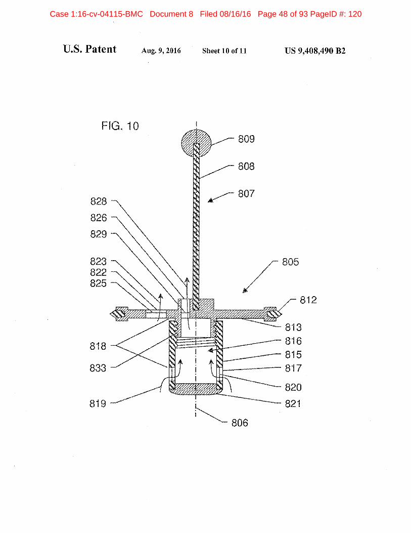
FIG 10 depicts vertical section of an altemative exem
plary embodiment ofa piston/filter plunger element including
an adjustable screw according to an embodiment of the inven
tion
FIG 11 depicts vertical section of an alteniative exem
plary embodiment of piston/filter plunger element including
an adjustable vent opening according to an embodiment of the
inventiosi
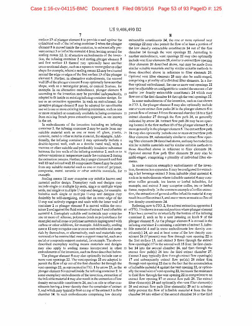
DETAILED DESCRIPTION flE SEVERALEMBODIMENTS
Referring tn FIG snlvent extractinn apparatus
according to an embodiment of the invention is shown con
figured similarly to french press type coffee or tea making
apparatus The solvent extraction apparatus comprises
exemplary walled cylinder infusing container containing
mixtureof extract and infusible material Plunger element
is adapted to fit within infusing container of solvent
extraction apparatus and to be moved within the infssing
container along vertical axis thereof such as central ver
tical axis by means of plunging means attached to the
plunger element The plunging means may comprise
central elongated handle cnmprising md and optional
knob for example which may be grasped by user to move
the plunger element The extraction apparatus may addi
tionally comprise lid 10 with central hole 11 through which
rodS may pass to assist in centering the plunger elements and
rod inside infasing container and prevent it from tilting
Plunger element additionally comprises sealing means 12
situated at the edge of first surface or wall 13 of the plunger
element which is oriented substantially transverse to the
vertical axis In use inside infusing container the first
surface 13 and sealing nieans 12 of the plunger element
define first chamber 14 containing the mixture of extract
and infusible material FIG shows the extraction apparatus in first or starting position for separating the extract
from the mixture of extract and infusible material in
infusing container
The plunger element further coniprises second surface
orwall 15 depending from and oriented substantially perpendicular to the first surface 13 defining second chamber 16
containing extract In sosne embodiments the second sur
to face or wall 15 may enclose the second chamber 16 whereasin other embodiments second chamber 16 may comprisepartially or completely open top and/or buttom for example
The joint between the first surface 13 and the second surface
15 is substantially leak proof with respect to extmct and
ts infusible material The second surface 15 of plunger ele
ment also comprises one or more extract flow openings 17In an exemplary embodiment at least portion of the one or
more extract flow openings 17 are situated at depfii 18
separated from the first surface 13 along the vertical axis
20 either above or below the first surface 13 The one or more
extract flow openings 17 are adapted to permit flow of extract
froni the first chamber 14 containing mixture of extract
and infusible material to the second chaniber 16 contain
ing extract as shown by arrow 19 In another embodiment
25 the second surface or wall 15 may depend from the first
surface 13 extending away from the first surface 13 at
non-perpendicular angle In an exemplary such embodiment
the second surface or waIl 15 may extend away from the first
surface 13 at an angle between about 45-85 degrees for
30 example The further embodiments of the inventive plunger
element described below in FIGS 2-11 may also be similarly
adapted such that the second surface or wall may extend awayfrom the first surface at non-perpendicular angle
The one or more extract flow openings 17 in the second
is wall 15 typically comprise one or more filter elements 20
within or across the extract flow openings 17 such that extract
flowing through the openings 17 must substantially pass
through the filter elements 20 The one or more filter elements
20 may be desirably adapted to control the passage of iofus
40 ible niaterial through the openings 17 to allow substantial
separation of the extract from the infusible material In
some embodiments apertu.mresin the filter elements 20 may be
small enough to substantially exclude the infusible material
from passing through the openings 17 The filter elements 20
45 may be made from any suitable material such as one or
combination of polymer metal ceramic composite cloth
felt paper or other suitable materials for example The filter
elements 20 can be formed by any suitable method such as by
one or more of stamping chemical etching laser etching
50 molding weaving welding machining sintering felting
foaming paper making piercing ur any other method
adapted to create small and preferably unithrm apertures
common embodiment of filter element 20 includes screen
or mesh having many apertu.mres comprised of suitable mate-
55 rial as described above Additionally the filter elements 20
niay be multi-staged coniprising plurality of individual
filter elements
In the exemplary embodiment of the present invention
shown in FIG the infusing container comprises sub-
60 stantially vertical walled cylinder container with substan
tially circular cross-section the first surface 13 of plunger
element is substantially circular in cross-section adapted to
fit inside the cylindrical infusing container and the second
surface 15 is substantially cylindrical with substantially
65 circular cross-section and plug or end wall 21 closing the
bottom of the second wall 15 Sealing means 12 are situated
aroraid the substantially circular outside edge of the first
Case 1:16-cv-04115-BMC Document 8 Filed 08/16/16 Page 52 of 93 PageID #: 124
US 9408490 B2
surface 13 uf plunger element tn provide seal against the
cylindrical wall of the inlissing container when the plunger
element is moved inside the container to substantially pre
vent extract or inThsible material from leaking arormd the
sealing means 12 In alternative embodinsents of the inven
tioo the inftssing container asid mating plunger element
and first surface 13 thereof may optionally have aoother
cross-sectional shape stich as square or rectangular or other
shape for example wherein sealing means 12 may be situatedaround the edge or edges of the first surface 13 of the plunger
element Further in alternative embodiments the second
wall 15 of the plunger elementS may optionally have another
shape such as rectangular prism or conical frustum for
example In an alternative embodiment plrmger element
according to the invention may be provided independently 15
adapted to fit inside an existing inftssingcontainer design for
use as an extraction apparatus In such an embodiment thc
inventive plunger element may be adapted for retrofittable
use with one or more existing infusing cootainers such as one
or more standard or commonly available iofusing containers
from existing french press extraction apparati as are known
in the art
Isi embodiments of the invention including ass infusing
container the infusing container may be made from any
suitable material such as one or more of glass plastic
ceramic metal or other suitable material for example Addi
tionally the infusing container may optionally include
double-layered wall such as double metal wall with
vacuum or other suitable and preferably insulative substance
between the two walls of the infusing container such as to
reduce variations in temperature inside the container during
the extraction process Further the plunger elements and first
wall 13 and second wall IS components thereof may be made
from any suitable material such as one or more ofi polyoier
composite metal ceramic or other suitable materials for
example
Sealing means 12 may comprise any suitable known seal
material aodlor design Exemplary such seal designs mayinclude siogle or multiple lip seals single or multiple wiper
seals and single or multiple U-cup seal designs for example
Suitable such siogle or multiple U-cup seal designs maydesirably be self-energising such that an outer edge of the
U-cup seal actively engages and seals with the inner wall of
container as plunger element is nioved within the contaioer and against the fluid mixture of extract and ioThsible
material Exemplary suitable seal materials may comprise
one or more oh silicone polymers such as polyurethane for
example and silicone or polymermaterials impregnated with
carbon or other additives for example Additionally sealing
means 12 may coniprise one or more such suitable seal materials by themselves or alternatively such seal materials maysurround or be overmolded over support material such as
metal or composite support material for example The above-
described exemplary sealing means materials and designs
may also apply to sealing means incorporated in other
embodiments ofthe invention such as those described below
The pluoger element may also optionally include one or
more vent openings 22 The vent openings 22 are adapted to
permit the flow of air out of the first chamber 14 through the
vent openings 22 as represented in FIG by arrow 23 as the
plunger element is moved inside the ioftssiog container In
some exemplary eoibndiments of the invention extraction of
the inftssible material may also result in the extraction of low
density extractable constituents 24 such as oils or other constituents having lower density than the remainder of extract
and which may typically float on top of the extract in first
chamber 14 In such embodiments comprising low density
25
extractable constituents 24 the one or more optiooal vent
openings 22 may also permit the flow of at least portion of
the low density extractable constituents 24 out of the first
chamber 14 through the vent openings 22 According to
another eoibodiment vent openings 22 may also optionally
include vent filter elements 25 similar to extract flow opening
filter elements 20 described above and may be made from
similar suitable materials and by similar suitable methods to
those described above in reference to filter elements 20
Optional veot filter elements 25 may also he multi-staged
cosnprising plurality of individual filter elements In fur
ther optional embodiment the one or more vent openiogs 22
maybe adjustable or configurable to control the amount of air
andlor low density extractable constituents 24 which mayflow out of the first chamber 14 through the vent openings 22
In some embodiments of the invention such as that shown
in FIG the plunger element may also optionally ioclode
one or more extract flow paths 26 in the plunger element to
20 permit flow of extract from the second chamber 16 to third
extract chamber 27 through the flow path 26 as generally
indicated by arrow 28 Extract flow path 26 may be an opening located in the first surfhce 13 of the plunger element or
more generally in the plunger elementS The extract flow path
26 may also optionally include one or more extract flow path
filter elements 29 substantially similar to extract flow opening filter elements 20 described above asid snay be made from
similar suitable materials and by similar suitable methods to
those described above in reference to filter elements 2030
Optional extract flow path filter elements 29 may also be
multi-staged comprising plurality of individual filter ele
ments
In some common exemplary embodiments of the ioveo
tion the extractioo apparatus snay be coofigured hr extract
ing hot beverage extract from infusible plant material
such as io embodimeots where infusible snaterial snay com
prise coffee grounds tea leaves or herbal infhsibles for
exaoiple and extract may comprise coffee tea or herbal
40 tisaoe respectively In the common example of coffee extrac
tion the extraction of ground coffee infusible material mayresult in coffee extract and one or more aromatic coffee oil
low density constituents 24
Referring now to FIG the solvent extractioo apparatus
45 ofFIG is shown in second position where plunger elesnent
has been moved to substantially the bottom of the infusing
container such as by user pressing on knob of the
plunger element As the plunger element is oioved in the
infusing container containing mixture of extract iofus
St ible material and in some embodiments low density con
stituents 24 air and at least some of the low density constituent 24 if preseot may how through vent opening 22 in
the first surface 13 and extract flows through the extract
flow openings 17 in the second wall 15 from the first eham
55 her 14 into the second chamber 16 and then through the
extract flow paths 26 into the third extract chaoiber 27
Extract may typically flow through extract flow openings
17 and subsequently extract flow paths 26 rather than
through vent opening 22 due to the fact that the accumulation
to of infusible material against the vent opening 22 or optionally the small size ofvent opening 22 increases the resistance
to fluid flow through the vent opening 22 in comparison to an
extract flow opeoiog 17 or extract flow path 26 The extract
filter elements 20 and optionally also vent filter elements
65 25 and extract flow path filter elements 29 act to substan
tially prevent the flow of infusible material from the first
ehan3ber 14 into either of the second chamber 16 or the third
Case 1:16-cv-04115-BMC Document 8 Filed 08/16/16 Page 53 of 93 PageID #: 125
US 9408490 B2
chamber 27 effectively and desirably separating the extract
and potentially also low density constituent 24 if present
from the infusible material
Following the separation of extract and potentially also
low density constituent 24 if present fromthe infusible material by moving the pluoger element inside the infusing
container the separated extract and any low density
constituent 24 may be stored in the third extract chamber 27
until desired for use without further contact with infusible
material The infusing container niay also optionally
include pouring spout 30 which may be used to pour the
separated extract from the third chamber 27 for consumptionor other use The infitsing container may further optionally include handle not shown to facilitate lifting or moving the extraction apparatus by user
Referring to FIG vertical section of an exemplary
embodiment of plunger element 105 according to an
embodiment of the invention is shown configured similarly
to french press type coffee and/or tea maldng plunger
Plunger element 105 is adapted to fit within an infusing container similar to that shown in FIG and to be moved within
the infusing container not shown along vertical axis
thereof such as central vertical axis 106 by means such as
central elongated handle 107 Handle means 107 may coin
prise rod 108 and optional knob 109 for example which maybe grasped by user to move the plunger element 105
Plu.uiger element 105 additionally comprises sealing means
112 situated at the edge of first surface or wall 113 of the
plunger element 105 which is oriented substantially trans
verse to the vertical axis 106
The plunger element 105 further comprises second sur
face or wall 115 depending from and oriented substantially
perpendicular to the first surface 113 defining fluid cham
ber 116 wluch is substantially open at one end Similar to the
plunger element shown in FIG the joint between the first
surface 113 and the second surface 115 of plunger 105 is
substantially leak proof and the second surface 115 of
plunger element 105 also comprises one or more extract flow
openings 117 wherein at least portion of the one of more
extract flow openings 117 is situated at depth 118 separated
from the first surface 113 below the first surthce 113 along
the vertical axis 106 Tbe one or more extract flow openings
117 are adapted to permit flow of extract into chamber 116 as
shown by arrow 119
The one or more extract flow openings 117 in the second
wall 115 typically comprise one or more filter elements 120
within or across the extract flow openings 117 such that
extract flowing through the openings 117 as shown by arrow
119 must substantially pass through the filter elements 120
Similar to exemplary plunger elementS of FIG the one or
more filter elements 120 may he desirably adapted to control
the passage of inlusible material through the openings 117 to
allow substantial separation of the extract from the infusible
material and optionally apertures in the filter elements 120
may be small enough to substantially exclude the infusible
material from passing through the openings 117 Extract flow
path filter elements 120 are substantially similar to extract
flow opening filter elements 20 described above and may bemade from similar suitable materials and by similar suitable
methods to those described above in reference to filter ele
ments 20In the exemplary embodiment of the present invention
shown in FIG the first surface 113 of plunger element 105
is substantially circular in cross-section adapted to fit inside
cylindrical infusing container and the second surface 115 is
substantially cylindrical with substantially circular cross-
section and plug or end wall portion 121 closing the bottom
10
of the second surface or wall 115 Sealing means 112 are
essentially similar to the sealing means 12 described above
with respect to FIG and are situated around the substan
tially circular outside edge of the first surface 113 of plunger
element 105 perfanning the same sealing function as
described above with reference to FIG In alternative
embodiments of the invention the infusing container and
mating plunger element 105 and first surface 113 thereofmay
optionally have another cross-sectional shape such as
to square or rectangular or other shape for example wherein
sealing means 112 may be situated around the edge or edges
of the first surface 113 of the plunger element 105 Further in
alternative embodiments the second wall 115 of the plungerelement 105 may optionally have another shape such as
is rectangular prism or conical frustum for example
The phmger element 105 and first wall 113 and second wall
115 components thereof may be made from suitable materials
such as described above in reference to plunger element of
FIG As in plunger element plunger element 105 may20 optionally also include one or more vent openings 122
adapted to permit the flow of air through the vent openings
122 as represented in FIG by arrow 123 as the plunger
element 105 is moved inside the infusing container In some
exemplary embodiments of the invention extraction of the
25 infusible material may also result in the extraction of low
density extractable constituents such as oils or other constitu
ents having lower density than the remainder of the extract
and which may typically float on top of the extract In such
embodiments comprising low density extractable constitn
30 ents the one or more vent openings 122 may also permit the
flow of at least portion of the low density extractable constituents Vent openings 122 may also optionally include vent
filter elements 125 similar to extract flow opening filter ele
ments 120 described above and may be made from similar
suitable materials and by similar suitable methods to those
described above in reference to filter elements 120 Optional
vent filter elements 125 may also be multi-staged comprising
plurality of individual filter elements In an alternative such
embodiment the one or more vent openings 122 may be
40 adjustable or configurable to control the amount of low den
sityextractable constituents which may flow through the vent
openings 122In another embodiment the one or more vent openings 122
may be operable to control an amount of infusible material
45 which may pass through vent openings 122 In one example
thereof vent openings 122 may desirably substantially pre
vent passage of infusible material In another example
thereof vent openings may be adjustable or configurable such
that they are operable to controllably permit desired amount
50 of infusible material through the vent openings 122 and into
the separated extract in the extract chamber 27 the passage
of controlled and typically very small amount of infusible
material through the vent openings 122 into separated
extract may be desirable in some cases or by some users to
55 affect the taste of the separated extract for example
In the exemplary embodinnent of the present invention
shown in FIG the fluid chamber 116 defined by the second
surface 115 is substantially open at the top and thereby per
mits flew of extract out of fluid chamber 116 such as through
so extract flow path 126 as generally indicated by arrow 128 as
plunger 105 is moved through an infusing container contain
ing tnixture of extract and infusible material similar to as
shown with plungers in FIG In other exemplary embodi
nients the fluid chamber 116 defined by the second surface
os 115 may be partially closed or narrowed at the top
Referring to FIG vertical section of an exemplary
embodiment of plunger element 205 according to an
Case 1:16-cv-04115-BMC Document 8 Filed 08/16/16 Page 54 of 93 PageID #: 126