Exhibit B - Connecticut...Terminal Block F Nokia FSEB Alarm Connections 13-24 T-Mobile Standard...
44
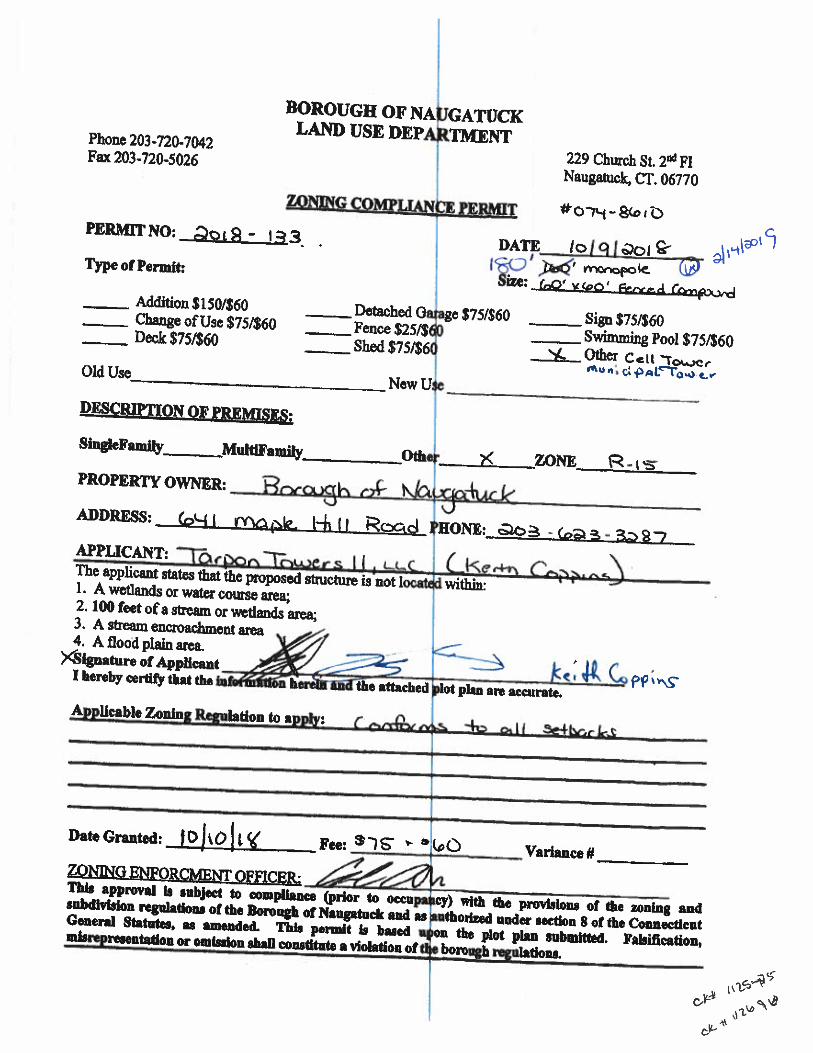
Northeast Site Solutions 420 Main Street, Unit 2 Sturbridge MA 01566 March 29, 2019 Ms. Melanie Bachman Executive Director Connecticut Siting Council Ten Franklin Square New Britain, CT 06051 RE: Tower Share Application 641 Maple Hill Road, Naugatuck, CT 06770 Latitude: 41-29-17.24 N Longitude: -73-01-12.73 W T-Mobile Site Number: CTNH325D- NSD Dear Ms. Bachman: This letter and attachments are submitted on behalf of T-Mobile Northeast LLC (“T-Mobile”). T-Mobile plans to install antennas and related equipment at the tower site located at 641 Maple Hill Road in Naugatuck, Connecticut. The existing monopole is owned by Tarpon Towers and was approved by the Borough of Naugatuck on October 10, 2018. The tower will be used by the Borough of Naugatuck emergency services, whose antennas will be located at the top of the tower. T-Mobile will install four (4) 600/700MHz antennas, four (4) 1900/2100 MHz antennas, four (4) 2100 MHz antennas and twelve (12) remote radio units (‘RRUs’) at a centerline height of 167 feet on the existing 180-foot monopole tower. Three (3) hybrid cables and additional ancillary coax between the antennas & RRU’s will also be installed on the tower. T-Mobile’s equipment cabinets and one (1) Delta 25KW DC Generator – 250 gallon double walled self-contained tank with fuel sensor will be placed within T-Mobile’s 260 sq ft lease area. The generator requires two (2) 20 minute run cycles annually. As shown, in the included are plans by Proterra Design Group, dated March 12, 2019, attached as Exhibit A. Also included is a structural letter prepared by Proterra dated March 28, 2019, confirming that the existing tower is structurally capable of supporting the proposed equipment, attached as Exhibit B. Please accept this letter as notification pursuant to Regulations of Connecticut State Agencies 16-50aa, of T- Mobile’s intent to share telecommunications facility pursuant to R.C.S.A. 16-50j-88. In accordance with R.C.S.A., a copy of this letter is being sent to Honorable N. Wendell Hess III, Mayor, Borough of Naugatuck, Ed Carter, Zoning Enforcement Officer, Borough of Naugatuck. The Borough of Naugatuck is also the property owner. Tarpon Towers is tower owner The planned modifications of the facility fall squarely within those activities explicitly provided for in R.C.S.A. 16- 50j-89. 1. The proposed modification will not result in an increase in the height of the existing structure. The top of the monopole tower is 180-feet; T- Mobile’s proposed antennas will be located at a center line height of 167-feet.
Transcript of Exhibit B - Connecticut...Terminal Block F Nokia FSEB Alarm Connections 13-24 T-Mobile Standard...

Northeast Site Solutions 420 Main Street, Unit 2 Sturbridge MA 01566
March 29, 2019
Ms. Melanie Bachman Executive Director Connecticut Siting Council Ten Franklin Square New Britain, CT 06051
RE: Tower Share Application 641 Maple Hill Road, Naugatuck, CT 06770 Latitude: 41-29-17.24 N Longitude: -73-01-12.73 W T-Mobile Site Number: CTNH325D- NSD
Dear Ms. Bachman:
This letter and attachments are submitted on behalf of T-Mobile Northeast LLC (“T-Mobile”). T-Mobile plans to install antennas and related equipment at the tower site located at 641 Maple Hill Road in Naugatuck, Connecticut. The existing monopole is owned by Tarpon Towers and was approved by the Borough of Naugatuck on October 10, 2018. The tower will be used by the Borough of Naugatuck emergency services, whose antennas will be located at the top of the tower.
T-Mobile will install four (4) 600/700MHz antennas, four (4) 1900/2100 MHz antennas, four (4) 2100 MHz antennas and twelve (12) remote radio units (‘RRUs’) at a centerline height of 167 feet on the existing 180-foot monopole tower. Three (3) hybrid cables and additional ancillary coax between the antennas & RRU’s will also be installed on the tower. T-Mobile’s equipment cabinets and one (1) Delta 25KW DC Generator – 250 gallon double walled self-contained tank with fuel sensor will be placed within T-Mobile’s 260 sq ft lease area. The generator requires two (2) 20 minute run cycles annually. As shown, in the included are plans by Proterra Design Group, dated March 12, 2019, attached as Exhibit A. Also included is a structural letter prepared by Proterra dated March 28, 2019, confirming that the existing tower is structurally capable of supporting the proposed equipment, attached as Exhibit B.
Please accept this letter as notification pursuant to Regulations of Connecticut State Agencies 16-50aa, of T-Mobile’s intent to share telecommunications facility pursuant to R.C.S.A. 16-50j-88. In accordance with R.C.S.A., a copy of this letter is being sent to Honorable N. Wendell Hess III, Mayor, Borough of Naugatuck, Ed Carter, Zoning Enforcement Officer, Borough of Naugatuck. The Borough of Naugatuck is also the property owner. Tarpon Towers is tower owner
The planned modifications of the facility fall squarely within those activities explicitly provided for in R.C.S.A. 16-50j-89.
1. The proposed modification will not result in an increase in the height of the existing structure. The top of themonopole tower is 180-feet; T- Mobile’s proposed antennas will be located at a center line height of 167-feet.
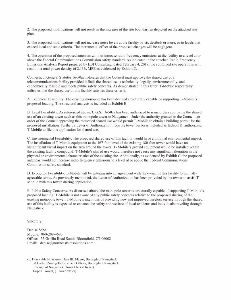
2. The proposed modifications will not result in the increase of the site boundary as depicted on the attached siteplan.
3. The proposed modifications will not increase noise levels at the facility by six decibels or more, or to levels thatexceed local and state criteria. The incremental effect of the proposed changes will be negligent.
4. The operation of the proposed antennas will not increase radio frequency emissions at the facility to a level at orabove the Federal Communications Commission safety standard. As indicated in the attached Radio Frequency Emissions Analysis Report prepared by EBI Consulting, dated February 4, 2019, the combined site operations will result in a total power density of 2.13% MPE as evidenced by Exhibit C.
Connecticut General Statutes 16-50aa indicates that the Council must approve the shared use of a telecommunications facility provided it finds the shared use is technically, legally, environmentally, and economically feasible and meets public safety concerns. As demonstrated in this letter, T-Mobile respectfully indicates that the shared use of this facility satisfies these criteria.
A. Technical Feasibility. The existing monopole has been deemed structurally capable of supporting T-Mobile’s proposed loading. The structural analysis is included as Exhibit B.
B. Legal Feasibility. As referenced above, C.G.S. 16-50aa has been authorized to issue orders approving the shared use of an existing tower such as this monopole tower in Naugatuck. Under the authority granted to the Council, an order of the Council approving the requested shared use would permit T-Mobile to obtain a building permit for the proposed installation. Further, a Letter of Authorization from the tower owner is included as Exhibit D, authorizing T-Mobile to file this application for shared use.
C. Environmental Feasibility. The proposed shared use of this facility would have a minimal environmental impact. The installation of T-Mobile equipment at the 167-foot level of the existing 180-foot tower would have an insignificant visual impact on the area around the tower. T- Mobile’s ground equipment would be installed within the existing facility compound. T-Mobile’s shared use would therefore not cause any significant alteration in the physical or environmental characteristics of the existing site. Additionally, as evidenced by Exhibit C, the proposed antennas would not increase radio frequency emissions to a level at or above the Federal Communications Commission safety standard.
D. Economic Feasibility. T-Mobile will be entering into an agreement with the owner of this facility to mutually agreeable terms. As previously mentioned, the Letter of Authorization has been provided by the owner to assist T-Mobile with this tower sharing application.
E. Public Safety Concerns. As discussed above, the monopole tower is structurally capable of supporting T-Mobile’s proposed loading. T-Mobile is not aware of any public safety concerns relative to the proposed sharing of the existing monopole tower. T-Mobile’s intentions of providing new and improved wireless service through the shared use of this facility is expected to enhance the safety and welfare of local residents and individuals traveling through Naugatuck.
Sincerely,
Denise Sabo Mobile: 860-209-4690 Office: 35 Griffin Road South, Bloomfield, CT 06002 Email: [email protected]
cc: Honorable N. Warren Hess III, Mayor, Borough of Naugatuck Ed Carter, Zoning Enforcement Officer, Borough of Naugatuck Borough of Naugatuck, Town Clerk (Owner) Tarpon Towers, ( Tower owner)


MAPL
E HI L L
RD
KENT
S T
CAD BUR Y P L
M U L B E RRY ST
SIMS BE RR Y R D
WO ODS IDE DR
WI ND S OR P L
FAW
N M
EADO
W DR
AR BO R AVE
O L D E F A R M L N
M U L B E RRY ST
MAPL
E HI L L
RD
M U L B E RRY ST M U L B E RRY ST
MAPL
E HI L L
RD
M U L B E RRY STM U L B E RRY ST
SI MS BE RR Y R D
Disclaimer: This map is for informational purposes only.All information is subject to verification by any user.
The Borough of Naugatuck and its mapping contractors assume no legal responsibility for the information contained herein.
Map Produced March 20170 75 150 225 300
Feet
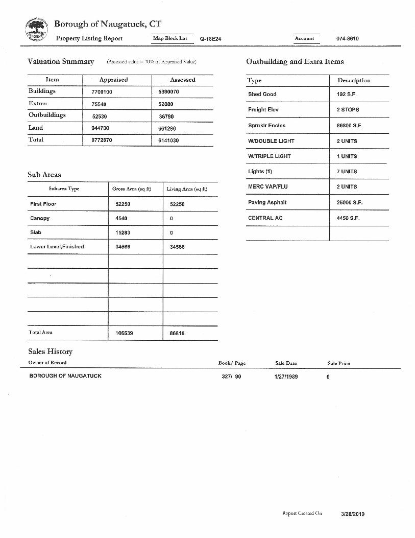
Borough of Naugatuck, Connecticut - Assessment Parcel MapAddress:
8
Parcel Account Number: 074-8610641 MAPLE HILL RD

Exhibit A
Proterra plans


© Copyright 2011 T-Mobile USA, Inc. All rights reserved. Confidential and proprietary information of T-Mobile USA, Inc. Not for distribution outside T-Mobile.
Delta PowerGen 25000 Design Document Diesel, DC, 25kW Model#PowerGen–25000 SKU#33658
The following are responsible for this project document:
Kevin Smith SR. Engineer (770) 256-3594
Project Design Spec Revision 1.0 Last Date:8/8/2018 5/14/2018
Final doc URL (~Dnnnnn):
Location Use the InfoRouter Search (Advanced) putting the Document ID (nnnnnn without the D) to find the location of the master document.
Template URL: http://docs.eng.t-mobile.com/InfoRouter/docs/~D423750 Slightly updated 1/2011

Delta PowerGen 25000 Design Document
T-Mobile USA, INC. Confidential Rev. 1.0 5/14/2018 2 of 10
Table of Contents
1 Introduction / Project Summary ......................................................................................................... 3 1.1 Purpose of Project 3 1.2 Feature Description 3 1.3 Dimensions 3
2 Fuel Tanks ............................................................................................................................................ 5 3 Controllers/Alarms .............................................................................................................................. 6
3.1 Interfaces and Alarming 6 4 Regulatory Requirements................................................................................................................... 8 5 Configuration/Diagrams ..................................................................................................................... 8 6 Maintenance ......................................................................................................................................... 9

Delta PowerGen 25000 Design Document
T-Mobile USA, INC. Confidential Rev. 1.0 5/14/2018 3 of 10
1 Introduction / Project Summary
1.1 Purpose of Project
T-Mobile’s nationwide cell site hardening plan is providing a refuelable backup power system capable of powering a site for a minimum of 48 hours before refueling is required. The purpose of this project is to give T-Mobile customers reliable service during power outages and provide a sufficient layer of coverage. This design document is for the Delta PowerGen 25000, which is a diesel DC generator with a capacity of 25kW.
1.2 Feature Description
The 25kW Delta PowerGen diesel generator is one of the DC generators selected as part of the T-Mobile RFP in support of the nationwide cell site hardening plan. The 25kW has a Level 2 acoustic enclosure. It is equipped with telecom HE rectifiers like in the Delta Hp Large SSC, -48V DC bus powered battery charger of 12V engine battery, Status/alarming via telecom standard dry contacts, WEB GUI/SNMP, and OBD2 Port for GEOTAB monitoring.
1.3 Dimensions
The dimensions of a level 2 Acoustic Enclosure in inches W83” x H78” x D38” (dimensions have been rounded up to the nearest inch)T-Mobile requires a 36-inch radius around the generator that will cover the hinged door and the panel style doors on the generator.

Delta PowerGen 25000 Design Document
T-Mobile USA, INC. Confidential Rev. 1.0 5/14/2018 4 of 10

Delta PowerGen 25000 Design Document
T-Mobile USA, INC. Confidential Rev. 1.0 5/14/2018 5 of 10
2 Fuel Tanks
The 25kW PowerGen has a 250 Gallon Double-Wall UL142 Base tank. Below is the Install drawing 25kW.
Delta PowerGen 25000 Design Document
T-Mobile USA, INC. Confidential Rev. 1.0 5/14/2018 6 of 10
3 Controllers/Alarms
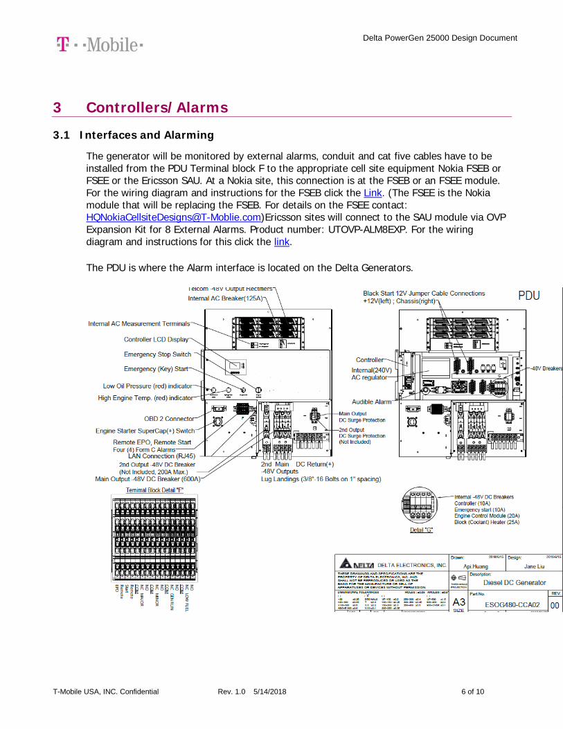
3.1 Interfaces and Alarming
The generator will be monitored by external alarms, conduit and cat five cables have to be installed from the PDU Terminal block F to the appropriate cell site equipment Nokia FSEB or FSEE or the Ericsson SAU. At a Nokia site, this connection is at the FSEB or an FSEE module. For the wiring diagram and instructions for the FSEB click the Link. (The FSEE is the Nokia module that will be replacing the FSEB. For details on the FSEE contact: [email protected])Ericsson sites will connect to the SAU module via OVP Expansion Kit for 8 External Alarms. Product number: UTOVP-ALM8EXP. For the wiring diagram and instructions for this click the link.
The PDU is where the Alarm interface is located on the Delta Generators.

Delta PowerGen 25000 Design Document
T-Mobile USA, INC. Confidential Rev. 1.0 5/14/2018 7 of 10
T-Mobile has four relays available from the Delta controller that are Low Fuel, Gen Run, Minor, Major. T- Mobile will utilize Normally Closed (NC) for alarms in terminal block F. Ericsson cabinets need to be equipped with the alarm expansion kit (UTOVP-ALM8EXP) to handle external alarms.
Terminal Block F Nokia FSEB Alarm Connections 13-24 T-Mobile Standard Alarms Terminal block F 2.Gen Run NC 4110 grd 4111 pin 13 Generator Running
Terminal block F 4.Major NC 4110 grd 4111 pin 14 Generator Alarm Critical Terminal block F 3. Minor NC 4110 grd 4111 pin 15 Generator Alarm NSI
Terminal block F 1. Low Fuel NC 4110 grd 4111 pin 16 Low Fuel Terminal Block F Ericsson Alarm 8expConnections T-Mobile Standard Alarms
Terminal block F 2.Gen Run NC - A5 Generator Running Terminal block F 4.Major NC - A6 Generator Alarm Critical Terminal block F 3. Minor NC - A7 Generator Alarm NSI
Terminal block F 1. Low Fuel NC - A8 Low Fuel
UTOVP-ALM8EXP OVP Expansion Kit for 8 External Alarms Qty
Product no Denomination
UTOVP-ALM8EXP OVP Expansion Kit for 8 External Alarms 1
NFD30234/08 OVERVOLTAGE ARRESTER/OVP-ALM 8 1
RPM777143/01200 CABLE WITH CONNECTOR/SIGNAL CABLE 2
66 block optional not included
Ericsson UTOVP- ALM8EXP
Delta PowerGen 25000 Design Document
T-Mobile USA, INC. Confidential Rev. 1.0 5/14/2018 8 of 10
4 Regulatory Requirements
Level 2 Acoustic Enclosure provides a noise level of 65dBA. It is EPA certified and meets NFPA 99 and 110 requirements(NFPA National Fire Protection Association). The PowerGen25000 DC generator engine is a Perkins Tier 4 engine and meets the EPA standards.
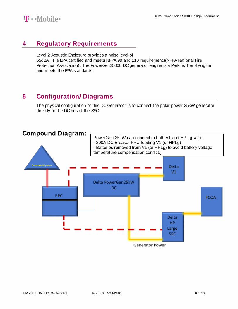
5 Configuration/Diagrams The physical configuration of this DC Generator is to connect the polar power 25kW generator directly to the DC bus of the SSC.
Compound Diagram:
PowerGen 25kW can connect to both V1 and HP Lg with: - 200A DC Breaker FRU feeding V1 (or HPLg) - Batteries removed from V1 (or HPLg) to avoid battery voltage temperature compensation conflict.)

Delta PowerGen 25000 Design Document
T-Mobile USA, INC. Confidential Rev. 1.0 5/14/2018 9 of 10
6 Maintenance
T-Mobile is recommending preventive maintenance to be performed every 250 hours of run-time or every 12 months, whichever comes first.
T-Mobile requires this minimum service checklist for the generator engine:
• Check engine mounts and support. Tighten fasteners.
• Check all the engine hoses and clamps for proper fit, and any signs of cracking and fatigue from wear.
• Inspect all belts for signs of cracking and fatigue from wear and adjust for proper tension.
• Inspect the exhaust system for leaks, burns and wet stacking. Drain exhaust line and tighten any clamps and flange bolts.
• Inspect silencer and plumbing for leaks, cracks or any other signs of wear.
• Inspect the system for fuel, oil and coolant leaks and signs of corrosion.
• Replace water separator.
• Replace water filter/ conditioner.
• Check Anti-Freeze (Spector-Analysis).
• Check coolant level and add, if needed.
• Inspect radiator mounting for signs or wear and cracking.
• Inspect/ clean air filter and change per manufacturer specifications.
• Inspect air intakes and outlets and tighten clamps and brackets, if applicable.
• Replace fuel filter.
• Inspect the carburetor fuel injection system, fuel injection pump and choke, if equipped. Adjust to manufacturers specifications.
• Change engine oil, oil filter and record the date on the filter casing.
• Check engine heater operation, if equipped.

Delta PowerGen 25000 Design Document
T-Mobile USA, INC. Confidential Rev. 1.0 5/14/2018 10 of 10
• Check and adjust the battery charger operations, and charge rate within the manufacturer’s recommended operating specifications.
• Inspect the battery housing, hardware connections, and cables for corrosion and wear.
• Check the battery electrolyte levels and specific gravity levels.
• Load test generator battery.
• Check, adjust and record generator output voltage, as necessary.
• Check and record the alternator charge rate.
• During inspection run the generator for 30 minutes under load. During this time, and after the engine is at full operational speed and has reached engine operating temperature; determine and record the condition of all inspection points: oil pressure, water/ coolant temperature, Fuel pressure, generator gauge, indicator operations, generator battery.
• Check the engine timing and adjust to manufacturers specifications, if necessary.
• Inspect, adjust and record governor and frequency, if necessary.
• Verify that the low fuel alarm is operational and configured correctly to trigger when the fuel tank reaches 50% of fuel tank capacity.
Check fuel level and refuel the generator during the preventive/ corrective maintenance visit.

Exhibit B
Structural Analysis


Exhibit C
EBI Consulting RF Emissions Report

EBI Consulting environmental | engineering | due diligence
21 B Street . Burlington, MA 01803 . Tel: (781) 273.2500 . Fax: (781) 273.3311
RADIO FREQUENCY EMISSIONS ANALYSIS REPORT EVALUATION OF HUMAN EXPOSURE POTENTIAL
TO NON-IONIZING EMISSIONS
T-Mobile Existing Facility
Site ID: CTNH325D
Naugatuck 641 Maple Hill Road
Naugatuck, CT 06770
February 4, 2019
EBI Project Number: 6219000311
Site Compliance Summary
Compliance Status: COMPLIANT
Site total MPE% of FCC general population
allowable limit:
2.13 %

EBI Consulting environmental | engineering | due diligence
21 B Street . Burlington, MA 01803 . Tel: (781) 273.2500 . Fax: (781) 273.3311
February 4, 2019
T-Mobile USA Attn: Jason Overbey, RF Manager 35 Griffin Road South Bloomfield, CT 06002
Emissions Analysis for Site: CTNH325D – Naugatuck
EBI Consulting was directed to analyze the proposed T-Mobile facility located at 641 Maple Hill Road,
Naugatuck, CT, for the purpose of determining whether the emissions from the Proposed T-Mobile Antenna Installation located on this property are within specified federal limits.
All information used in this report was analyzed as a percentage of current Maximum Permissible Exposure (% MPE) as listed in the FCC OET Bulletin 65 Edition 97-01and ANSI/IEEE Std C95.1. The FCC regulates Maximum Permissible Exposure in units of microwatts per square centimeter (W/cm2). The number of W/cm2 calculated at each sample point is called the power density. The exposure limit for power density varies depending upon the frequencies being utilized. Wireless Carriers and Paging Services use different frequency bands each with different exposure limits, therefore it is necessary to report results and limits in terms of percent MPE rather than power density.
All results were compared to the FCC (Federal Communications Commission) radio frequency exposure rules, 47 CFR 1.1307(b)(1) – (b)(3), to determine compliance with the Maximum Permissible Exposure (MPE) limits for General Population/Uncontrolled environments as defined below.
General population/uncontrolled exposure limits apply to situations in which the general population may be exposed or in which persons who are exposed as a consequence of their employment may not be made fully aware of the potential for exposure or cannot exercise control over their exposure. Therefore, members of the general population would always be considered under this category when exposure is not employment related, for example, in the case of a telecommunications tower that exposes persons in a nearby residential area.
Public exposure to radio frequencies is regulated and enforced in units of microwatts per square centimeter (μW/cm2). The general population exposure limits for the 600 MHz and 700 MHz frequency bands are approximately 400 μW/cm2 and 467 μW/cm2 respectively. The general population exposure limit for the 1900 MHz (PCS) and 2100 MHz (AWS) frequency bands is 1000 μW/cm2. Because each carrier will be using different frequency bands, and each frequency band has different exposure limits, it is necessary to report percent of MPE rather than power density.

EBI Consulting environmental | engineering | due diligence
21 B Street . Burlington, MA 01803 . Tel: (781) 273.2500 . Fax: (781) 273.3311
Occupational/controlled exposure limits apply to situations in which persons are exposed as a consequence of their employment and in which those persons who are exposed have been made fully aware of the potential for exposure and can exercise control over their exposure. Occupational/controlled exposure limits also apply where exposure is of a transient nature as a result of incidental passage through a location where exposure levels may be above general population/uncontrolled limits (see below), as long as the exposed person has been made fully aware of the potential for exposure and can exercise control over his or her exposure by leaving the area or by some other appropriate means.
Additional details can be found in FCC OET 65.
CALCULATIONS
Calculations were done for the proposed T-Mobile Wireless antenna facility located at 641 Maple Hill
Road, Naugatuck, CT, using the equipment information listed below. All calculations were performed per the specifications under FCC OET 65. Since T-Mobile is proposing highly focused directional panel antennas, which project most of the emitted energy out toward the horizon, all calculations were performed assuming a lobe representing the maximum gain of the antenna per the antenna manufactures supplied specifications, minus 10 dB for directional panel, was focused at the base of the tower. For this report the sample point is the top of a 6-foot person standing at the base of the tower.
For all calculations, all equipment was calculated using the following assumptions:
1) 1 UMTS channel (AWS Band – 2100 MHz) was considered for each sector of the proposedinstallation. These Channels have a transmit power of 40 Watts per Channel.
2) 2 LTE channels (PCS Band - 1900 MHz) were considered for each sector of the proposedinstallation. These Channels have a transmit power of 40 Watts per Channel.
3) 2 LTE channels (AWS Band – 2100 MHz) were considered for each sector of the proposedinstallation. These Channels have a transmit power of 60 Watts per Channel.
4) 2 LTE channels (600 MHz Band) were considered for each sector of the proposedinstallation. These Channels have a transmit power of 40 Watts per Channel.
5) 2 LTE channels (700 MHz Band) were considered for each sector of the proposedinstallation. These Channels have a transmit power of 20 Watts per Channel.
EBI Consulting environmental | engineering | due diligence
21 B Street . Burlington, MA 01803 . Tel: (781) 273.2500 . Fax: (781) 273.3311
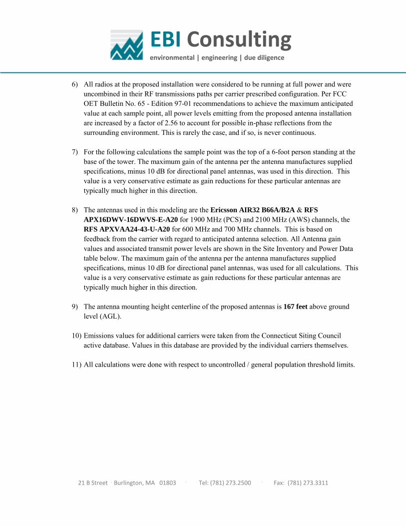
6) All radios at the proposed installation were considered to be running at full power and wereuncombined in their RF transmissions paths per carrier prescribed configuration. Per FCCOET Bulletin No. 65 - Edition 97-01 recommendations to achieve the maximum anticipatedvalue at each sample point, all power levels emitting from the proposed antenna installationare increased by a factor of 2.56 to account for possible in-phase reflections from thesurrounding environment. This is rarely the case, and if so, is never continuous.
7) For the following calculations the sample point was the top of a 6-foot person standing at thebase of the tower. The maximum gain of the antenna per the antenna manufactures suppliedspecifications, minus 10 dB for directional panel antennas, was used in this direction. Thisvalue is a very conservative estimate as gain reductions for these particular antennas aretypically much higher in this direction.
8) The antennas used in this modeling are the Ericsson AIR32 B66A/B2A & RFS
APX16DWV-16DWVS-E-A20 for 1900 MHz (PCS) and 2100 MHz (AWS) channels, theRFS APXVAA24-43-U-A20 for 600 MHz and 700 MHz channels. This is based onfeedback from the carrier with regard to anticipated antenna selection. All Antenna gainvalues and associated transmit power levels are shown in the Site Inventory and Power Datatable below. The maximum gain of the antenna per the antenna manufactures suppliedspecifications, minus 10 dB for directional panel antennas, was used for all calculations. Thisvalue is a very conservative estimate as gain reductions for these particular antennas aretypically much higher in this direction.
9) The antenna mounting height centerline of the proposed antennas is 167 feet above groundlevel (AGL).
10) Emissions values for additional carriers were taken from the Connecticut Siting Councilactive database. Values in this database are provided by the individual carriers themselves.
11) All calculations were done with respect to uncontrolled / general population threshold limits.

EBI Consulting environmental | engineering | due diligence
21 B Street . Burlington, MA 01803 . Tel: (781) 273.2500 . Fax: (781) 273.3311
T-Mobile Site Inventory and Power Data
Sector: A Sector: B Sector: C Sector: D Antenna #: 1 Antenna #: 1 Antenna #: 1 Antenna #: 1
Make / Model: Ericsson AIR32 B66A/B2A Make / Model: Ericsson AIR32
B66A/B2A Make / Model: Ericsson AIR32 B66A/B2A Make / Model: Ericsson AIR32
B66A/B2A Gain: 15.9 dBd Gain: 15.9 dBd Gain: 15.9 dBd Gain: 15.9 dBd
Height (AGL): 167 feet Height (AGL): 167 feet Height (AGL): 167 feet Height (AGL): 167 feet
Frequency Bands 1900 MHz (PCS) / 2100 MHz (AWS) Frequency Bands 1900 MHz (PCS) /
2100 MHz (AWS) Frequency Bands 1900 MHz (PCS) / 2100 MHz (AWS) Frequency Bands 1900 MHz (PCS) /
2100 MHz (AWS) Channel Count 4 Channel Count 4 Channel Count 4 Channel Count 4
Total TX Power(W): 200 Total TX
Power(W): 200 Total TX Power(W): 200 Total TX
Power(W): 200
ERP (W): 7,780.90 ERP (W): 7,780.90 ERP (W): 7,780.90 ERP (W): 7,780.90 Antenna A1
MPE% 1.07 Antenna B1
MPE% 1.07 Antenna C1
MPE% 1.08 Antenna D1
MPE% 1.07
Antenna #: 2 Antenna #: 2 Antenna #: 2 Antenna #: 2
Make / Model: RFS
APX16DWV-16DWVS-E-A20
Make / Model: RFS
APX16DWV-16DWVS-E-A20
Make / Model: RFS
APX16DWV-16DWVS-E-A20
Make / Model: RFS
APX16DWV-16DWVS-E-A20
Gain: 16.3 dBd Gain: 16.3 dBd Gain: 16.3 dBd Gain: 16.3 dBd Height (AGL): 167 feet Height (AGL): 167 feet Height (AGL): 167 feet Height (AGL): 167 feet
Frequency Bands 2100 MHz (AWS) Frequency Bands 2100 MHz (AWS) Frequency Bands 2100 MHz (AWS) Frequency Bands 2100 MHz (AWS)
Channel Count 1 Channel Count 1 Channel Count 1 Channel Count 1 Total TX
Power(W): 40 Total TX Power(W): 40 Total TX
Power(W): 40 Total TX Power(W): 40
ERP (W): 1,706.32 ERP (W): 1,706.32 ERP (W): 1,706.32 ERP (W): 1,706.32 Antenna A2
MPE% 0.24 Antenna B2
MPE% 0.24 Antenna C2
MPE% 0.24 Antenna D2
MPE% 0.24
Antenna #: 3 Antenna #: 3 Antenna #: 3 Antenna #: 3
Make / Model: RFS
APXVAA24-43-U-A20
Make / Model: RFS
APXVAA24-43-U-A20
Make / Model: RFS
APXVAA24-43-U-A20
Make / Model: RFS
APXVAA24-43-U-A20
Gain: 13.05 / 13.35 dBd Gain: 13.05 / 13.35 dBd Gain: 13.05 / 13.35 dBd Gain: 13.05 / 13.35 dBd Height (AGL): 167 feet Height (AGL): 167 feet Height (AGL): 167 feet Height (AGL): 167 feet
Frequency Bands 600 MHz / 700 MHz Frequency Bands 600 MHz /
700 MHz Frequency Bands 600 MHz / 700 MHz Frequency Bands 600 MHz /
700 MHz Channel Count 4 Channel Count 4 Channel Count 4 Channel Count 4
Total TX Power(W): 120 Total TX
Power(W): 120 Total TX Power(W): 120 Total TX
Power(W): 120
ERP (W): 2,479.78 ERP (W): 2,479.78 ERP (W): 2,479.78 ERP (W): 2,479.78 Antenna A3
MPE% 0.82 Antenna B3
MPE% 0.82 Antenna C3
MPE% 0.82 Antenna D3
MPE% 0.82
Site Composite MPE%
Carrier MPE%
T-Mobile (Per Sector Max) 2.13 %
No Additional Carriers NA
Site Total MPE %: 2.13 %
T-Mobile Sector A Total: 2.13 % T-Mobile Sector B Total: 2.13 % T-Mobile Sector C Total: 2.13 %
Site Total: 2.13 %

EBI Consulting environmental | engineering | due diligence
21 B Street . Burlington, MA 01803 . Tel: (781) 273.2500 . Fax: (781) 273.3311
T-Mobile Maximum MPE Power Values (Per Sector)
T-Mobile _Frequency Band /
Technology
(Per Sector)
#
Channels
Watts ERP
(Per Channel)
Height
(feet)
Total Power
Density
(W/cm2)
Frequency
(MHz)
Allowable
MPE
(W/cm2)
Calculated %
MPE
T-Mobile PCS - 1900 MHz LTE 2 1,556.18 167 4.32 PCS - 1900 MHz 1000.00 0.42%
T-Mobile AWS - 2100 MHz LTE 2 2,334.27 167 6.47 AWS - 2100 MHz 1000.00 0.65%
T-Mobile AWS - 2100 MHz UMTS 1 1,706.32 167 2.37 AWS - 2100 MHz 1000.00 0.24%
T-Mobile 600 MHz LTE 2 807.35 167 2.24 600 MHz 400.00 0.56%
T-Mobile 700 MHz LTE 2 432.54 167 1.20 700 MHz 467.00 0.26%
Total: 2.13%

EBI Consulting environmental | engineering | due diligence
21 B Street . Burlington, MA 01803 . Tel: (781) 273.2500 . Fax: (781) 273.3311
Summary
All calculations performed for this analysis yielded results that were within the allowable limits for general population exposure to RF Emissions.
The anticipated maximum composite contributions from the T-Mobile facility as well as the site composite emissions value with regards to compliance with FCC’s allowable limits for general population exposure to RF Emissions are shown here:
T-Mobile Sector Power Density Value (%) Sector A: 2.13 % Sector B: 2.13 % Sector C: 2.13 %
T-Mobile Maximum MPE % (Per Sector): 2.13 %
Site Total: 2.13 %
Site Compliance Status: COMPLIANT
The anticipated composite MPE value for this site assuming all carriers present is 2.13% of the allowable FCC established general population limit sampled at the ground level. This is based upon values listed in the Connecticut Siting Council database for existing carrier emissions.
FCC guidelines state that if a site is found to be out of compliance (over allowable thresholds), that carriers over a 5% contribution to the composite value will require measures to bring the site into compliance. For this facility, the composite values calculated were well within the allowable 100% threshold standard per the federal government.

Exhibit D
Letter of Authorization


Exhibit E
Recipient Mailings

P
Cut on dotted line.
Instructions
Click-N-Ship® Label Record
Electronic R
ate Approved #038555749
Thank you for shipping with the United States Postal Service!Check the status of your shipment on the USPS Tracking® page at usps.com
SH
IPTO
:
1. Each Click-N-Ship® label is unique. Labels are to be used as printed and used only once. DO NOT PHOTO COPY OR ALTER LABEL.
2. Place your label so it does not wrap around the edge of
the package. 3. Adhere your label to the package. A self-adhesive label
is recommended. If tape or glue is used, DO NOT TAPE OVER BARCODE. Be sure all edges are secure.
4. To mail your package with PC Postage®, you may schedule a Package Pickup online, hand to your letter carrier, take to a Post Office™, or drop in a USPS collection box. 5. Mail your package on the "Ship Date" you selected when creating this label.
Priority Mail® Postage:
From:
To:
Print Date:Ship Date:
Click-N
-Ship®
Trans. #:
Expected Delivery Date:
usps.com
US PO
STAG
E
* Retail Pricing Priority Mail rates apply. There is no fee for USPS Tracking® service on Priority Mail service with use of this electronic rate shipping label. Refunds for unused postage paid labels can be requested online 30 days from the print date.
Carrier -- Leave if N
o Response
Ref#: TS
NH
325D
USPS TR
AC
KIN
G #
$7.35
229 CH
UR
CH
ST
N. W
AR
RE
N H
ES
S, III
9405 5036 9930 0462 4417 23
DEBORAH CHASET-MOBILE/NSS35 GRIFFIN RD SBLOOMFIELD CT 06002-1351
9405 5036 9930 0462 4417 23 0073 5000 0010 6770
PRIO
RITY M
AIL 1-D
AY™C
004
9405 5036 9930 0462 4417 23
Mailed from
06002
Total460382498
Expected D
elivery Date: 04/02/19
0024
NA
UG
ATU
CK
CT 06770-4145
MA
YO
R-B
OR
OU
GH
OF N
AU
GA
TUC
K
Ref#: TS NH325D
062S0000000315
04/01/2019
USPS TRACKING # :
03/29/2019
DE
BO
RA
H C
HA
SE
T-MO
BILE
/NS
S35 G
RIFFIN
RD
SB
LOO
MFIE
LD C
T 06002-1351
Flat Rate E
nv
04/01/2019
N. WARREN HESS, IIIMAYOR-BOROUGH OF NAUGATUCK229 CHURCH STNAUGATUCK CT 06770-4145
$7.35$7.35
04/02/2019

P
Cut on dotted line.
Instructions
Click-N-Ship® Label Record
Electronic R
ate Approved #038555749
Thank you for shipping with the United States Postal Service!Check the status of your shipment on the USPS Tracking® page at usps.com
SH
IPTO
:
1. Each Click-N-Ship® label is unique. Labels are to be used as printed and used only once. DO NOT PHOTO COPY OR ALTER LABEL.
2. Place your label so it does not wrap around the edge of
the package. 3. Adhere your label to the package. A self-adhesive label
is recommended. If tape or glue is used, DO NOT TAPE OVER BARCODE. Be sure all edges are secure.
4. To mail your package with PC Postage®, you may schedule a Package Pickup online, hand to your letter carrier, take to a Post Office™, or drop in a USPS collection box. 5. Mail your package on the "Ship Date" you selected when creating this label.
Priority Mail® Postage:
From:
To:
Print Date:Ship Date:
Click-N
-Ship®
Trans. #:
Expected Delivery Date:
usps.com
US PO
STAG
E
* Retail Pricing Priority Mail rates apply. There is no fee for USPS Tracking® service on Priority Mail service with use of this electronic rate shipping label. Refunds for unused postage paid labels can be requested online 30 days from the print date.
Carrier -- Leave if N
o Response
Ref#: TS
-NH
325D
USPS TR
AC
KIN
G #
$7.35
229 CH
UR
CH
ST
ED
CA
RTE
R
9405 5036 9930 0462 4417 47
DEBORAH CHASET-MOBILE USA- NSS35 GRIFFIN RD SBLOOMFIELD CT 06002-1351
9405 5036 9930 0462 4417 47 0073 5000 0010 6770
PRIO
RITY M
AIL 1-D
AY™C
004
9405 5036 9930 0462 4417 47
Mailed from
06002
Total460382498
Expected D
elivery Date: 04/02/19
0024
NA
UG
ATU
CK
CT 06770-4145
BO
RO
UG
H O
F NA
UG
ATU
CK
-ZON
ING
EN
FOR
CE
ME
NT
OFFIC
ER
Ref#: TS-NH325D
062S0000000311
04/01/2019
USPS TRACKING # :
03/29/2019
DE
BO
RA
H C
HA
SE
T-MO
BILE
US
A- N
SS
35 GR
IFFIN R
D S
BLO
OM
FIELD
CT 06002-1351
Flat Rate E
nv
04/01/2019
ED CARTERBOROUGH OF NAUGATUCK-ZONING ENFORCEMENTOFFICER229 CHURCH STNAUGATUCK CT 06770-4145
$7.35$7.35
04/02/2019

P
Cut on dotted line.
Instructions
Click-N-Ship® Label Record
Electronic R
ate Approved #038555749
Thank you for shipping with the United States Postal Service!Check the status of your shipment on the USPS Tracking® page at usps.com
SH
IPTO
:
1. Each Click-N-Ship® label is unique. Labels are to be used as printed and used only once. DO NOT PHOTO COPY OR ALTER LABEL.
2. Place your label so it does not wrap around the edge of
the package. 3. Adhere your label to the package. A self-adhesive label
is recommended. If tape or glue is used, DO NOT TAPE OVER BARCODE. Be sure all edges are secure.
4. To mail your package with PC Postage®, you may schedule a Package Pickup online, hand to your letter carrier, take to a Post Office™, or drop in a USPS collection box. 5. Mail your package on the "Ship Date" you selected when creating this label.
Priority Mail® Postage:
From:
To:
Print Date:Ship Date:
Click-N
-Ship®
Trans. #:
Expected Delivery Date:
usps.com
US PO
STAG
E
* Retail Pricing Priority Mail rates apply. There is no fee for USPS Tracking® service on Priority Mail service with use of this electronic rate shipping label. Refunds for unused postage paid labels can be requested online 30 days from the print date.
Carrier -- Leave if N
o Response
USPS TR
AC
KIN
G #
$7.35
229 CH
UR
CH
ST
NA
NC
Y K
DIM
EO
9405 5036 9930 0462 4417 54
DEBORAH CHASET-MOBILE/NSS35 GRIFFIN RD SBLOOMFIELD CT 06002-1351
9405 5036 9930 0462 4417 54 0073 5000 0010 6770
PRIO
RITY M
AIL 1-D
AY™C
004
9405 5036 9930 0462 4417 54
Mailed from
06002
Total460382498
Expected D
elivery Date: 04/02/19
0024
NA
UG
ATU
CK
CT 06770-4145
TOW
N C
LER
K-B
OR
OU
GH
OF N
AU
GA
TUC
K
062S0000000101
04/01/2019
USPS TRACKING # :
03/29/2019
DE
BO
RA
H C
HA
SE
T-MO
BILE
/NS
S35 G
RIFFIN
RD
SB
LOO
MFIE
LD C
T 06002-1351
Flat Rate E
nv
04/01/2019
NANCY K DIMEOTOWN CLERK-BOROUGH OF NAUGATUCK229 CHURCH STNAUGATUCK CT 06770-4145
$7.35$7.35
04/02/2019

P
Cut on dotted line.
Instructions
Click-N-Ship® Label Record
Electronic R
ate Approved #038555749
Thank you for shipping with the United States Postal Service!Check the status of your shipment on the USPS Tracking® page at usps.com
SH
IPTO
:
1. Each Click-N-Ship® label is unique. Labels are to be used as printed and used only once. DO NOT PHOTO COPY OR ALTER LABEL.
2. Place your label so it does not wrap around the edge of
the package. 3. Adhere your label to the package. A self-adhesive label
is recommended. If tape or glue is used, DO NOT TAPE OVER BARCODE. Be sure all edges are secure.
4. To mail your package with PC Postage®, you may schedule a Package Pickup online, hand to your letter carrier, take to a Post Office™, or drop in a USPS collection box. 5. Mail your package on the "Ship Date" you selected when creating this label.
Priority Mail® Postage:
From:
To:
Print Date:Ship Date:
Click-N
-Ship®
Trans. #:
Expected Delivery Date:
usps.com
US PO
STAG
E
* Retail Pricing Priority Mail rates apply. There is no fee for USPS Tracking® service on Priority Mail service with use of this electronic rate shipping label. Refunds for unused postage paid labels can be requested online 30 days from the print date.
Ref#: TS
NH
325D
USPS TR
AC
KIN
G #
$7.35
STE
420
TAR
PO
N TO
WE
RS
9405 5036 9930 0462 6568 13
DEBORAH CHASET-MOBILE USA- NSS35 GRIFFIN RD SBLOOMFIELD CT 06002-1351
9405 5036 9930 0462 6568 13 0073 5000 0063 4205
PRIO
RITY M
AIL 3-D
AY™C
002
9405 5036 9930 0462 6568 13
Mailed from
06002
Total460398634
Expected D
elivery Date: 04/04/19
0004
KE
ITH C
OP
PIN
S
BR
AD
EN
TON
FL 34205-78731001 3R
D A
VE
W
Ref#: TS NH325D
062S0000000315
04/01/2019
USPS TRACKING # :
03/29/2019
DE
BO
RA
H C
HA
SE
T-MO
BILE
US
A- N
SS
35 GR
IFFIN R
D S
BLO
OM
FIELD
CT 06002-1351
Flat Rate E
nv
04/01/2019
KEITH COPPINSTARPON TOWERS1001 3RD AVE WSTE 420BRADENTON FL 34205-7873
$7.35$7.35
04/04/2019