Exhibit 1 - Gas Free Senecagasfreeseneca.com/wp-content/uploads/2015/01/Ex.-1-Clark-Report... ·...
61
Exhibit 1 Cavern Integrity Report H. C. Clark, Ph.D.
Transcript of Exhibit 1 - Gas Free Senecagasfreeseneca.com/wp-content/uploads/2015/01/Ex.-1-Clark-Report... ·...

Exhibit 1
Cavern Integrity Report H. C. Clark, Ph.D.

Cavern Integrity Analysis
Finger Lakes LPG Storage, LLC
January 15, 2015
H.C. Clark, Ph.D.

1
I. Introduction
Finger Lakes LPG Storage, LLC (FLLPG) has applied for a permit to store liquid
petroleum gas (LPG) in two underground galleries—known as Gallery 1 and Gallery 2—in the
Watkins Glen Brine Field along the west side of Seneca Lake.1 I was asked to prepare this
technical report analyzing whether there are any risks to the integrity of the caverns proposed for
LPG storage that are not addressed by FLLPG’s application materials or the draft permit
conditions published by the New York State Department of Environmental Protection (DEC) in
connection with this project. In my opinion, there are serious questions remaining about the
solution-mined salt caverns in this area and their future integrity, and the data gaps are serious
enough to warrant denial of the permit. Moreover, even if sufficient new studies are performed
to supply the missing information, and the application materials are revised to provide a
comprehensive and accurate picture of the caverns and their geological context, it will be
impossible to respond in a timely and effective way to any problems that may develop, unless
significant additional conditions are included in the permit.
My report examines the geology of the area and its solution-mined caverns, with special
focus on Galleries 1 and 2, the caverns bordering Galleries 1 and 2 on the south and north, and
the high-angle strike-slip (tear) fault along the eastern boundary of the project. A thorough
understanding of the surrounding geology is critical because that geology will be the container
for LPG, and the caverns were not simply hollowed from a homogeneous and isotropic mass
(that is, a uniform material with the same properties in all directions). The geology where these
caverns have been dissolved has been folded, thrust faulted, and cut by vertical faults, leaving a
complex geology that has controlled the development of the Watkins Glen Brine Field. The
development, shape, and behavior of the caverns are, in large part, a product of that geology,
acting over the history of each cavern, and for most of them, it’s a very long history.
Questions about how this geology is involved with the caverns of the Watkins Glen Brine
Field are important because problems involving salt storage caverns, wells, and mines have been
documented over many years.2 Examples of such problems in both bedded salt formations and
domal salt include:
Mid-1990s collapse of the Retsof, NY, bedded salt room and pillar mine, where a 500-
foot-by-500-foot block of ceiling fell, leading to the flooding and closure of the mine.
Yaggy bedded salt storage cavern leak and 2001 fire at Hutchinson, KS.
Salt mine collapse in 1974 forming the 300-foot-diameter Cargill Sink at the Hutchinson,
KS, bedded salt mine.
1 “The Watkins Glen brine field, located in Schuyler County, is in the south central part of New York State, along
the west shore of Lake Seneca . . . . It is approximately four miles north of the Village of Watkins Glen.” (Jacoby,
1962: 506) As used in this report, the “Watkins Glen Brine Field” or “Watkins Glen” refers to that area, including
the wells and galleries in the Town of Reading that FLLPG proposes to use for LPG storage. 2 Reports of these and other problems follow the list of references at the end of this report.

2
Explosion at Mt. Belvieu, TX, when stored LPG leaked from salt dome through corroded
well casing, then to town sewer system.
Ongoing collapse of Oxy3 Cavern at Bayou Corne, Louisiana, where a solution mined
cavern in the Napoleonville Salt Dome has breached the salt wall, and subsequent
collapse has chimneyed to the surface, creating a sinkhole that continues to expand.
Although the caverns listed above do not represent precise analogues of the FLLPG Galleries,
the history should remind us that accidents do happen, and when they do, they can be very
serious. No two caverns are exactly alike, if only because the local geology is different, and each
requires careful study, controlled solutioning, and meaningful and frequent monitoring—to avoid
the problems of these examples.
The basic question presented by FLLPG’s application is whether or not there is adequate
evidence of long-term cavern integrity—so DEC and the public can have confidence that
problems encountered elsewhere will not happen at Seneca Lake—and the answer is no. The
evidence is inadequate because much of the information that a geologist would ordinarily expect
to find about the surrounding geology and features of the caverns is missing, incomplete, or
incorrect. Moreover, the information that is available indicates that Galleries 1 and 2 and
surrounding caverns—some more than half a century old—show effects of age and anomalies
suggesting that long-term integrity may not be possible.
Documents supporting FLLPG’s application for the underground storage permit were
heavily redacted before public release, so public information about the site area is available
largely from published articles and an application released by the New York State Electric Gas
Corporation (NYSEG) for compressed air energy storage (CAES) nearby. That information was
enough to raise a number of preliminary questions about the project, but it was not enough to
answer them.
To summarize the critical issues I identify:
A professional geologist assessing the integrity of solution-mined salt caverns proposed
for hydrocarbon storage will begin with the applicant’s maps and cross-sections, which
are supposed to depict the geology of the area, including stratigraphy and faults, as well
as the extent, contours, and developmental history of the caverns. Comprehensive and
accurate maps and cross-sections serve three crucial functions: (1) they allow analysts to
flag issues that may become serious problems; (2) they help to identify where additional
study or monitoring is needed; and (3) they expedite response when something goes
wrong, by enabling analysts to understand quickly what happened and what corrective
action is needed. FLLPG’s application lacks the comprehensive and detailed maps and
cross-sections that provide the framework for an adequate assessment of cavern integrity.

3
Some readily available and relevant data (for example, from publications by Charles
Jacoby, the geologist who developed these caverns) is missing
and some of the visually displayed information is incorrect. When the
omissions are cured, and the mistakes are corrected, the need for further study is
immediately apparent. The map and cross-sections should be supplemented with the
results of additional studies I identify below as well as known sources of information,
both published and from company files evidently available to FLLPG.3 Cavern integrity
analysts should not have to comb through thousands of pages of application materials—
as I have had to do—to piece together a comprehensive picture of the geology and
storage cavities. It is dangerous and irresponsible not to have the resource readily
available, if a problem develops in the future.
For example, there are zones or planes of weakness in the walls and roofs of these
caverns—such as thrust faults, fractures, and high-angle strike-slip faults—that are not
shown on the maps and cross-sections. Some of these faults served as pathways for
communication between wells in the past or for accidental transmission of fluids to the
surface, and some have been linked to roof collapse. FLLPG insinuates that the
documented Jacoby-Dellwig Fault does not exist or is sealed. Full studies of faults and
fractures should be required, all such zones of weakness should be evaluated as potential
pathways for communication, and the complete results of that analysis should be
described and portrayed graphically in revised application materials, including in a
monitoring plan.
The caverns of the Watkins Glen Brine Field have grown outward and upward, and this
growth will continue. Outward cavern growth may lead to communication with nearby
caverns or fault zones.
Upward growth may lead to partial roof failure or complete collapse—as is
evident from the rubble piles in the caverns of the Watkins Glen Brine Field. Sonars
from 2009 and 2011 show that the roof of FLLPG Gallery 2 (Cavern 58)—which
previously was abandoned because of a prior collapse—has reached the Camillus shale,
appears to be sinking at the center, and may be unstable. This uncontrolled growth is
partially depicted in the limited sonar slices shown on the cross-sections and
3 The 2010 Reservoir Suitability Report submitted by FLLPG refers to “US Salt company files” (2010-5-14, BSK to
DEC – NOIA Response Reservoir Suitability Report (redacted) at 1). Companies routinely maintain records of
project development and performance over the lifetime of a project and after it has ended, so FLLPG may have
access to additional historical documentation from company files. Such detailed records are important in
understanding what has happened if there is a failure of some sort—such as a cavern roof fall—and in deciding how
to address the problem. 4


5
II. Overview of Relevant Geology
To place my analysis in context, it is important to understand the salt cavern solutioning
process in its geological context. Making caverns like those in the Watkins Glen Brine Field is a
matter injecting fresh water into a well, dissolving the bedded salt, and withdrawing the resulting
brine. The geologic cross-section in Figure 1 below shows an injection well and a withdrawal
well typical of the multi-well caverns at the Watkins Glen Brine Field. (Jacoby, 1973). In fact,
this is a cross-section of two of the wells involved in Gallery 1 of the FLLPG project—Wells 33
and 43—now part of a mega-cavern joining Wells 33, 43, 34, and 44.
Figure 1: Wells 33 and 43
Source: Jacoby, 1973

6
Both wells were first drilled, then fresh water was pumped into one under pressure—creating a
hydraulically fractured connection along a fault plane connecting the two wells, and solution of
the cavity followed. The wells still exist and can be opened for logging and to lower sonar
devices or other equipment used to monitor cavern pressure, salinity, and seismic events with
periodic or continuous measurements.
The stratigraphy (rock layers) shown in Figure 1, like that of the Watkins Glen Brine
Field generally, involves salt beds (shown with the letters and subscripts) and interbedded layers
of shale, limestone and dolomite (shown by the patterns). The cross-section illustrates the folded
rocks and salt layers, along with thrust faults—one is just below elevation -1700 with the
notation “dislocation.” The original hydraulic fracture in this example was near the bottom of
the cavern, and as solutioning of the cavity progressed, rock layers—which did not dissolve—
were undermined and fell into the cavern, creating the “rubble pile.” The tubing through which
the fresh water was injected and the brine was removed was cut off as the process moved upward
(and cut off pipe pieces are depicted in the rubble pile).
The caverns of the brine field are solutioned in bedded salt of the Silurian Syracuse
Formation, sandwiched between Vernon shales below and Camillus shale (shale, dolomite and
gypsum) above. The stratigraphic column in Figure 2, below, from the proposed NYSEG CAES
plan, describes the nearby rock section (PB Energy Storage Services, 2011:5). Here, the
interbedded salt and rock layers are designated by letters, then numbers and numbers within (like
F1/1 and F1/2). The nomenclature has changed through the years and the lettering in Figures 1
and 2 may not match exactly.

PROTECTED MATERIALS
7
Figure 2: Column of Rock Layers
Source: PB Energy Storage Services, 2011


9
another in stacks of repeated sections, cut again by high-angle strike-slip faults (Jacoby and
Dellwig, 1973). The FLLPG site-specific, thrust fault thickened, salt, and the effect of the high-
angle strike-slip fault, are shown on Figure 4 below, a salt isopach (thickness) map of the vicinity
from the NYSEG CAES application (PB Energy Storage Services, 2011). This is the complex
that makes up the walls, floors, and roofs of the caverns in the Watkins Glen Brine Field, most of
which are about a half-century old. Those walls, floors, and roofs reflect both the area’s long-
term geologic history and events that occurred during individual cavern development.
III. Assessment of Cavern Integrity
My assessment of cavern integrity is organized around a map showing Watkins Glen
Brine Field wells and gallery outlines and three cross-sections created by FLLPG to outline its
Figure 4: Salt Isopach Map
Source: PB Energy Storage Services,
2 11

10
plan. I begin with an overview of the caverns in the area, move to an examination of the cross-
sections provided in the application, and then consider faulting and other geological features
affecting the caverns and concerns about cavern growth. I offer observations at each stage in the
context of additional information that I have obtained from public sources. My report concludes
with a set of recommendations for studies, tests, and monitoring.
A. Gallery Map
How are these
caverns related or could they become related; that is, what happens to the rest if there is a
problem at one? To answer that question, it is essential to understand a lot more information
—some of which I add in this report.
There needs to be a
comprehensive study of all the caverns in the brine field and development of a “state of the brine
field” map that includes geology as well as information about each cavern and how it is related
to others.
Much of this added information was developed
by International Salt geologist Charles Jacoby. He was able to use geologic mapping of
structural grain and associated planes of weakness to plan pairs of wells, where fractures would
develop along preferred pathways between the pressured and the interceptor well. Most of the
caverns in the Watkins Glen Brine Field were formed by this hydraulic fracturing from one well
to another, and the coalescent history has resulted in some complex, large elongate cavern
shapes.
6

11
Table 1: Well Pairs and Hydraulic Fracture Connections
Year
Well
Pumped
for
Fracture
Target
Well Connected?
Well
Unintentionally
Connected
Note
1956 28 27 Yes
1955 25 23 NoFluid pumped through Well
25 went to "vacuum"
41 42 No 37
40 39 No 42
1962 33 32 No 34 (north)
29 34 No 32Fluid traveled south along
Jacoby-Dellwig Fault
1962 29 34 No surface
Fluid reached surface 1/2-
mile north, along Jacoby-
Dellwig Fault.
1962 33 34 Yes
Thrust fault caused fluid to
reach well at unintended
location.
30 31 Yes
Thrust fault caused fluid to
reach well at unintended
location.
33 43 Yes
1963 35 36 Yes
1963 37 38 Yes
Reference
Jacoby, 1962, 1969
Jacoby, 1962
Jacoby, Dellwig, 1973,
Jacoby, 1965
Jacoby, 1969
Jacoby, 1973
Jacoby, Dellwig, 1973
Jacoby, Dellwig, 1973
Jacoby, Dellwig, 1973
Jacoby, Dellwig, 1973
Jacoby, 1965
Jacoby, 1969
Jacoby, 1969
There is a
lot more about hydraulic fracturing pathways that would be good to know, and a lot more
hydraulic fracturing was done or attempted at the Watkins Glen Brine Field. This missing
information would illuminate weaknesses in the rocks that created the pathways for hydraulic
fracture flow and may explain present cavern growth behavior.
Charles Jacoby wrote a number of papers about geology and cavern research and
development, including articles with a number of examples of well behavior in the Watkins Glen
Brine Field and descriptions of the geology that influenced this behavior. Table 1 below is a
partial list of well pairs subject to hydraulic fracturing that were documented by Jacoby. I
Jacoby’s knowledge about the regional structural grain (the near east-west Corbett Point
Syncline) allowed him to plan locations of connections where there had been only apparently


13
For example, the salt isopach map in Figure 4 shows the detail of the section in the area of this
cavern project, and that cumulative salt thickness, built by thrust faulting, should be shown
The significance of the thrust faults in this region is that, as nearly
horizontal bedding plane features, they represent horizontal planes of weakness that have
functioned as pathways for hydraulic fracture fluid flow. The faults, related hydraulic fracture
connections, and the differences in salt, shale, and dolomite layer properties influenced the
creation of all of the caverns of the Watkins Glen Brine Field, including the caverns that FLLPG
storage proposes to use for storage. The salt caverns here are not solutioned out of a
homogeneous and isotropic mass, and the caverns reflect this geology. The differences in the
salt and rock remain, along with the folds, fractures, and faults that are part of the walls and roofs
of these caverns.
Showing rock and salt layers as solid, intact materials, where a cavern in fact is filled with
broken rock, is inaccurate and misleading. It is important to know what these cavern systems
look like, how and where these caverns are connected, and how the geology may affect the
system including these caverns.
Each of the three cross-sections is examined below, with reference to mark-ups attached
to this report as Exhibits B–D.
1. Cross-Section AA’ (revised 8-28-14)
This west-to-east cross-section begins at the left edge of the diagram with Cavern 58, or
FLLPG Gallery 2, and then depicts the subsurface along the southern border of FLLPG property,
incorporating the Arlington natural gas Caverns 30, 31, 28, and 27. The inset on the lower left
shows the stratigraphic context of the interbedded salt and rock in the detailed cross-section at
the top. The letters with subscripts on the left edge and near the right edge name the interpreted

14
layers of salt (shown as white), and the interbedded rock layers (shown as a red pattern).
Typically, rock core description data and/or geophysical logs are superposed or referenced on a
cross-section to support the interpretations and allow independent verification, but that is not the
case here. The addition to cross-section AA’ of the log data developed by Jacoby (in his
published papers) and the logs for Well 58 (included in the application, e.g., 2010 Reservoir
Suitability Report, Exs. 5 and 6) would be helpful.
Cavern 58 will be discussed in more detail later, but some basic information requires
immediate correction. Two rock layers are depicted abutting Cavern 58 in unlikely locations.
One layer is shown a third of the way up in the new cavern being solutioned above the collapsed
original and passing through the 2011 and 2013 sonar outlines (likely a drafting error). The
other rock layer, shown beneath and apparently supporting the new Cavern 58, conflicts with the
underlying information in the application. The implied structural support beneath the new
Cavern 58 raises an important question: Is the layer real, making its future over the previous
Cavern 58 rubble pile somewhat precarious? Or, is the new Cavern 58 floored on the rubble of
the lower Cavern 58 roof collapse, and the continuous bed pictured an error? According to the
well status report in the Reservoir Suitability Report, the base of the new Cavern 58 is “top of
rubble,”8 making the depiction as solid rock an error. The phrase “top of rubble” here and at
several places on the cross-section indicates that there is rubble between the old and new cavern
floors and that, as Cavern 58 has been solutioned, the relatively insoluble interbedded rock has
fallen and filled the base of the cavern. A complete cross-section should show the volumes now
filled by this rock. The rubble-filled historic cavern outline for Cavern 58 is shown on
Exhibit B.
a. Caverns 27, 28, 30, 31, and 46
Moving to the east on cross-section AA’, the galleries of Caverns 30 and 31and Caverns
28 and 27 are part of the Arlington natural gas storage expansion project recently approved by
the Federal Energy Regulatory Commission. This proposal was the subject of detailed
comments, and most of the comments and FERC’s responses are available for review. FERC
has asked for “a new sonar survey of Gallery 2, through all three cavern wells, to obtain the
current size of the gallery, the size and shape of the rubble pile, and the shape of the roof around
each well.”9 That is, for the gallery involved with the 400,000-ton roof fall described by Jacoby,
Arlington not only must develop measurements of the currently open cavern, but also must
obtain measurements that fully characterize the size and shape of the rubble pile at the bottom of
the complete gallery. The latter measurement likely will require seismic testing, because sonar
cannot penetrate the rubble.
Information missing from cross-section AA’ is available from Jacoby studies of these
specific caverns. The 1967 cross-section of these caverns (Jacoby, 1969), shown below in
8 2010-5-14, BSK to DEC – NOIA Response Reservoir Suitability Report (redacted) (Ex. 9 at 2).
9 FERC, Order Issuing Certificate and Reaffirming Market-Based Rates, 147 FERC ¶ 61,120, at ¶ 31 & Engineering
Condition 3 (May 15, 2014).

15
Figure 5: Wells 27, 28, 30, and 31
Source: Jacoby 1969
Figure 5, below, was developed after their initial hydraulic fracture connection. It provides a
clearer picture of the actual situation here, in contrast with the current open space measured by
recent sonars above beds depicted as continuous on FLLPG cross-section AA’. The information
on this Jacoby cross-section should be disclosed on cross-section AA’, but it is not.
Figure 5 shows the outlines of the caverns, the hydraulic fracturing connections between
caverns, thrust faulting and tear faulting, in addition to the more detailed stratigraphy here that
Jacoby developed from core samples and geophysical logs. The notation in the middle of the
rectangular shape at the base of Cavern 30, “Fallen Rock Mass,” describes a 400,000-ton block
that fell from the roof (outlined by sonar). I have sketched the cavern outlines developed from
the 1967 sonars on cross-section AA’ and have attached the marked cross-section as Exhibit B to
this report, to allow comparison.
Also, on FLLPG cross-section AA’, note the “Top of Rubble” arrows between Caverns
30 and 31 and the “Estimated Location of Pressure Connection” arrow between the two
caverns—two features that help to reconcile the Jacoby cross-section with cross-section AA’(in
addition to the depths shown on the Jacoby cross-section). Corresponding locations of “Top of
Rubble” and “Estimated Location of Pressure Connection” appear on cross-section AA’ for

16
Figure 6: Wells 46 and 27
Source: Jacoby, 1973
Caverns 28 and 27, enabling the match with the Jacoby cross-section there, as well. Additional
published sonar measurements (Jacoby, 1973) of Cavern 27 provide information about the
upward path of the cavern roof.
There is a cautionary tale about Cavern 27, the basis for the Jacoby research paper related
to this additional sonar. Cavern 27 sonar was used to guide the drilling of Well 46 to recover
LPG that had migrated upward, as roof fall developed out and away from the original Well 27.
He noted that additional LPG might be trapped above weakened rock leaves of the then-present
cavern roof. This rock is now part of the rubble pile noted on AA’.
Figure 6 (Jacoby 1973) shows Wells 46 and 27. Well 46 was drilled to recover trapped
LPG and likely did not extend to the depth shown on cross-section AA’. Cross-section AA’,
with the addition of information from these sonar studies, would provide a picture of the cavern
advancing from Jacoby’s initial work, through the Well 46 experiment, and on to the present roof
outline.
My mark-up of cross-section AA’ in Exhibit B shows cavern outlines and the Jacoby-
Dellwig Tear Fault, shown in Figure 3 above between Caverns 31 and 28 and in Figure 4 parallel
to the shore of Seneca Lake. Thrust faulting shown on the Jacoby cross-section and discussed in
his 1973 article with respect to the thickened salt in Well 27 also should be added to cross-
section AA’. The locations of the thrust faults were developed from the repeated signatures
shown on gamma logs from Wells 27, 28, 30, and 31 and discussed in several Jacoby papers.
Jacoby discussed subsidiary faulting related to both of the major faults shown on his cross-
section, and that faulting should be recognized and plotted on cross-section AA’. The original
sonar information and the geophysical logs that were the basis for Jacoby’s cross-sections and

17
interpretations—and that are necessary to provide a complete account of the geology in the area
covered by cross-section AA—are likely in salt company files available to FLLPG. Once
completed, the revised cross-section AA’ should show the thrust faults and tear faults that
explain the variations in salt and rock layers shown on the 8/28/14 cross-section AA’ now in the
application.
In response to a Notice of Incomplete Application with questions from DEC about faults,
FLLPG discussed only the Camillus shale above the interbedded salt and rock layers and
repeated the conclusion that thrust faults do not involve the Camillus.10
But the thrust faults and
tear faults that are part of the overall geology,
The appropriate time to present
interpretations of beds above and below the deformed salt is after all the geological information
is presented visually in the cross-sections.
b. Cavern 58
Figure 7 below is my mark-up of the portion of cross-section AA’ depicting Cavern 58,
which is FLLPG Gallery 2. This cavern has been a focus of concern for a long time. It could be
described as the combination of two caverns: (1) the new one with its roof at the Camillus shale,
the upper bound of the interbedded salt and rock layers, and with its base outlined by the 2009
sonar, with a “morning glory” shape, and (2) the original attempt at cavern development, below
the new one, as outlined by the 1997–1999 sonars, which now is filled with rubble, the result of a
roof collapse and consequent abandonment. FLLPG shows them as isolated on cross-section
AA’, but in fact they are connected, as I show on Exhibit B.
10 2010-05-14, BSK to DEC – NOIA Response (redacted) at 8.


19
Reports and conversations with Larry Sevenker prior to the last
loggings appeared that the cavern at Well 58 was progressing
normally. The latest logging indicated that the roof of the cavern
had collapsed and filled with rubble. Mr. Sevenker further
reported that it appeared that the upper formations may have been
in a fractured and faulted zone and that a small magnitude
earthquake could have damaged the cavity.
Other (partially redacted) documents disclosed by DEC pursuant to a Freedom of Information
Law Request (but not included in the documents released to the public for this proceeding ) make
it clear that the Cavern 58 project ended because of concerns that questionable geology
(“fractured and faulted zone”) in the immediate vicinity made it unwise to place a cavern there.12
The cavern had collapsed, and continued to collapse each time they pulled up tubing and tried to
work again, so the well was plugged and sealed.
FLLPG attempts to discredit Mr. Sevenker
This explanation fails for several reasons. First, the cavern developers were “[u]nable to sonar
survey due to cavity conditions” (Jan. 8, 2001 report);
Second, the presence of open hole from
the top of the abandoned area to the top of the salt was known at the time and disclosed on the
plugging report.
Cross-section AA’ shows the “original” cavern at its
original position; what is there now has been solutioned above the original cavern.
Exhibit B
demonstrates that neither alternative is correct; rather, the new cavern was solutioned above the
old. The serious questions remaining about the integrity of Cavern 58, given its earlier
catastrophic collapse, cannot be explained away by impugning the reputation of a geologist with
first-hand knowledge of the event.
12 These documents include the letter quoted above; page 3 of a report dated January 8, 2001, on the inability to use
sonar in Well 58 (apparently from the files of DEC petroleum geologist William Glynn), and the 2003 plugging
report and cover letter from the consultant, Mr. Sevenker. These documents are collected and attached to this report
as Exhibit E. 13


21
. The fact that there is
, but no such attempt with respect to Caverns 30 and 31 and 28 and 27,
increases concerns about FLLPG’s misrepresentation of conditions in the caverns.
My concerns about a broader analysis of the caverns bordering proposed FLLPG
Gallery 2 mirror my concerns,
and are reflected in FERC’s insistence upon further study of the rubble piles and conduits
as a condition of approving Arlington’s gas storage expansion. Complete and accurate
information about caverns bordering the FLLPG project is crucial because the Arlington caverns
holding and cycling compressed natural gas could fail—in turn jeopardizing the integrity of the
adjacent FLLPG caverns. Exhibit B shows the southern border of the proposed LPG storage
caverns to be far more complicated and potentially compromised than shown in cross-section
AA’. DEC should analyze the new information that FERC has required from Arlington before
determining whether to grant FLLPG a permit for LPG storage.
Finally, more study is needed not only of Cavern 58’s rubble-filled base but also of its
unsupported rock roof. FLLPG has gone to some length to demonstrate the healing power of
salt, but it now has at least two caverns with flat or sagging rock roofs. FLLPG’s claim that
thrust faulting does not appear to affect the Camillus shale
—two things not expected in a uniform
shale.
Thus, FLLPG’s own records about the rock roof
raise serious and unanswered questions about Cavern 58’s suitability for LPG storage. DEC’s
permit determination should be deferred until after it has a full and correct understanding of
Gallery 2 and the bordering caverns, and until that additional study is complete, the application
lacks sufficient data to show that the reservoir is adaptable for storage purposes.
C. Cross-section BB’
14

22
1. FLLPG Gallery 1
Specifically, the Jacoby (1973)
cross-section, reproduced above as Figure 1, illustrates the early history of the cavern originally
created when Well 33 was hydraulically fractured to Well 43,
First, the Jacoby cross-section in Figure 1 shows a thrust fault cutting (at depth 2449) just
above the cavern that existed at the time, which was formed by the connection of Wells 33 and
43. That fault forced the rock and salt beds up and over one another within the Silurian section,
The thickened salt mass found in Well 34 was noted by Jacoby (1969) in
discussing the northern involvement of thrust faulting.
While the fault and folds shown in Figure
1 are largely now part of the rubble pile, they are also part of the walls of the cavern.
these faults are planes
of weakness that could serve as fluid pathways or influence future cavern deformation.
The Jacoby cross-section clarifies that, as salt was dissolved, the
rock layers above the former salt were no longer supported and fell to the bottom, forming the
rubble shown. That process began at the base and moved up,
with accumulated rubble below.

23
Jacoby shows the top of the original cavity as 2490 total depth at Well 33,
Figure 1 also shows an apparently well cemented casing at Well 43, but void space
around the casing at Well 33 from the cavity as it existed then up to about 2010 depth.
Beginning with the area
beneath Cavern 44, the Well Status and Condition Report lists “Top of rubble, bottom of existing
cavern” as 2423 feet for Well 44,
For Cavern 34,
the Well Status and Condition Report lists the “Top of rubble, bottom of existing cavern” as
2383 feet,16
15 2010-5-14, BSK to DEC – NOIA Response Reservoir Suitability Report (redacted) (Ex. 9 at 2).
16 Id. at Ex. 9 at 1.

25
and 43, near the base of the Syracuse, and then subsequent solution up from there. The hydraulic
fracture that connected Well 33 to Well 43 was apparently a second event. Here, Jacoby (1965)
described an unintended fracture connection where Well 33 fractured to Well 34, rather than the
intended target, Well 32.
Well # 33 was an injection well with an intended target of Well
# 32 across a distance of 735 feet. Unexpectedly, it connected with
Well # 34, or almost due north, a distance of 745 feet. Within 24
hours after the fracture had been initiated, brine was being
produced by the target well. The volume of brine produced
quickly reached a point where it was proportional to the volume of
water injected. The quality of brine with respect to calcium and
magnesium chlorides was extremely high, thus being relatively
poor for the production of evaporated salt. Pump pressures
remained extremely high despite the fact that large quantities of
salt were extracted. No second plateau ever developed.
It was surmised that fracturing fluid had passed horizontally along
a faulted zone with at least a portion of the travel route being in
shale layers.
Jacoby’s articles demonstrate that there was a hydraulic fracturing operation that
connected Wells 33 and 43 (illustrated in Jacoby, 1973) and an operation that connected Well 33
to Well 34 (described in Jacoby, 1965). Both of these fracture pathways were near the base of
the Syracuse, but they had to have taken independent routes in order to develop pressure for each
connection. These routes were involved with the zones of weakness related to faulting.
Jacoby wrote more about the role of faulting between Wells 33 and 34, describing the
pressure variation experience:
In fracturing Well 33 to 34, alternate buildup and recession of
pumping pressures indicated that the solution channel was being
closed by rock movement from time to time. In the light of
subsequent geologic information, the occurrence of intermittent
collapse should have been unexpected, inasmuch as in this area of
the brine field the major thrust has broken up, into and through the
No. 3 salt. Faulting above the cavity created by solution between
Wells 33 and 34 may have resulted in a weakness which led to the
observed periodic collapse and pressure buildup. It is over this
area that the major thrust bifurcates at several points, creating a
series of planes of weakness in the section overlying the solution
zone.
(Jacoby, 1973) (emphasis added).

26
Observations such as these, made by the US Salt geologist involved with the creation of
these caverns, make it clear that a time sequence describing the role of geology in the history of
each cavern is necessary in order to give an accurate portrayal of the current situation.
Information like the presence and position of the major thrust fault and bifurcated thrust faults,
along with the rubble-filled caverns developed in a time sequence and other information,


28
.
A professional geologist examining a project expects to see accurate, clearly identified,
and consistent data on cross-sections that can be traced to underlying information;
29
more data is needed to show that the Gallery 1 reservoir is safe for LPG
storage.
D. Cross-section CC’

30
Cavern 29 is the cavern close to or in the Jacoby-Dellwig Fault,
This cavern was the injection well that was supposed to create
a hydraulic fracture connection with Well (now Cavern) 34. Instead, Well (now Cavern) 29
fractured both to what is now Cavern 32, some
distance to the south (toward the viewer perpendicular to the cross-section), and to the ground
surface about a half-mile north (away from the viewer perpendicular to the cross-section). This
north-south fracture, considered in light of geophysical logs, mapping of the salt thickness, and
Appalachian-related features in the area, led Jacoby to identify a near vertical strike-slip fault
with about 1200 feet of offset—the Jacoby-Dellwig Fault (Jacoby 1973). The fault, along with
related north-south tear faults, is a zone of weakness, it has served as a fluid transmission
pathway in the past, and it may do so again. It therefore is important that the major and minor
faulting be fully characterized, that its role as a fluid pathway be evaluated, and that the Jacoby-
Dellwig fault be included in the cavern system monitoring plan.
FLLPG addresses the Jacoby-Dellwig Fault as follows:
Either ongoing or periodic pressure tests would be valuable sources of
information, if a problem occurs.

31
Whether a fault exists is determined by examination of regional data, and there are
multiple studies of the Jacoby-Dellwig Fault (Jacoby and Dellwig, 1973; Jacoby, 1965; Jacobi,
2002; FERC Arlington, 2014). That the Jacoby-Dellwig Fault is not sealed is indicated by the
movement through it of fracture fluid a half-mile north and a half-mile up to the surface.
Moreover, the hydraulic fracture pathway from Well 29 to Well 32 had to pass through the
Jacoby-Dellwig Fault, which is located between the two wells. If the fault is sealed and cannot
account for the uncontrolled hydraulic fractures from Well 29, then we lack an explanation for
the fluid movement. Either there are other yet unidentified pathways from the well or fluid
escaping a cavern can travel randomly and emerge anywhere there is a pressure differential
(including to the ground surface); neither alternative is comforting, and both cry out for
additional study.
If
Cavern 29’s development was influenced by the north-south Jacoby-Dellwig Fault or related
faults, there may be other linear features nearby—and the linear east side of a large part of
Gallery 1 is certainly one feature that should be investigated. All the relevant sonar surveys
should be made available for this purpose. The characterization of the Jacoby-Dellwig Fault and
related faults is important since it represents an area of weakness and a potential fluid pathway.
IV. Conclusion and Recommendations
The caverns that FLLPG proposes for LPG storage are part of the geology from which
they’ve dissolved—and over their history, each has responded to that geology. Galley 1 (the
mega-cavern of connected Caverns 33, 43, 34, and 44), was solutioned a half-century ago
Gallery 2 (Cavern 58), collapsed once and is being
solutioned again above the rubble of what was there before.
All of these issues, summarized here and
described in more detail in this report, have been the subject of concerns expressed by DEC in
repeated NOIAs, and FLLPG’s responses have only raised more questions that require further
inquiry.
The deficiencies identified in this report can be addressed only through the submission of
revised documents, including maps and cross-sections reflecting complete and accurate
information, which will require additional data collection and performance of technical studies.
At least the following documents should be filed:
32
A comprehensive and accurate map of the Watkins Glen Brine Field.
Revised cross-sections, with complete and correct depictions of the underlying geologic
and cavern information. Preparation of the cross-sections will require:
o (i) collection and compilation of relevant historical information about the wells
and caverns and their geological context, including information from published
literature and information in affiliated company files;
o (ii) performance of additional technical studies, including seismic surveys
(modified refraction, reflection, and vertical seismic profiling), to fill data gaps
identified in this report, such as the shape and volume of rubble-filled portions of
all caverns;
the relationship between Cavern 29 and the Jacoby-Dellwig Fault, and the
pathway from Cavern 29 to the ground surface;
o (iii) incorporation of that information into cross-sections that accurately illustrate
geologic features and fully characterize the caverns, including the rubble piles and
conduits, with comprehensive Keys to all features displayed; and
o (iv) submission of all data underlying the cross-sections
in well-
organized and meaningfully labeled electronic files.
Specifically, the cross-sections should provide full historical comparison of all sonar
information, superposed on common axes (derived from underlying full sonar histories of
each cavern developed using historical data superposition), and the data displayed should
enable the reader to ascertain: the total extent of caverns, including hanging ledges and
areas created by solutioning or hydraulic fracturing that are now under rubble; cavern
growth over time; fault involvement with well and cavern development; intended and
unintended hydraulic fracture paths; and other factors or anomalies that may be disclosed
during additional study. All thrust and high-angle strike-slip faults, including the Jacoby-
Dellwig Fault, should be located, characterized, and identified on the cross-sections.
Documentation showing the full three-dimensional extent and historical development of
the caverns, to supplement the cross-sections—that is, the detailed information
underlying the representative cross-section diagrams. Several full sonar surveys have
been made over the lifetime of each cavern. Each of these surveys involves synthesis of
sonar data points into a series of vertical and horizontal slices that provide a three-
dimensional picture of the particular cavern at that point in time. Often, the sonar
acquisition firm provides not only the current sonar data, but also superposes the sonar
slices with historical sonar data for the same slices, allowing comparison and evaluation
of trends over the time period of the surveys. Examples of the value of these
comparisons can be seen for the vertical sonar slices shown on the cross-sections and
noted historically by line color and the date next to each. All of the sonars for all of the
caverns should be produced for the record and expert review.

33
A revised Reservoir Suitability Report or other narrative comprehensively and accurately
describing the facts underlying the completed and corrected cross-sections and the three-
dimensional studies.
A written plan for monitoring all thrust and high-angle strike-slip faults and for
addressing any anomalies or problems identified through review of the cross-sections and
three-dimensional studies.
Ideally, the issues conference would be postponed until the foregoing documents are filed,
members of the public (including experts) have an opportunity to review them, and the new
information can be incorporated into petitions for party or amicus status. Without the revised
documents, FLLPG has not provided sufficient data to demonstrate that the Galleries it proposes
to use are appropriate for storage, the serious cavern integrity risks that I have identified cannot
be ruled out, and therefore DEC should refuse to issue FLLPG a permit for LPG storage.
If the revised documents are submitted, and a permit ultimately is issued, DEC should
require additional monitoring of the storage facility. The present monitoring plan focuses on
periodic measurements, mostly of the condition of the wells and the effects of moving LPG and
brine in and out of the caverns, and the caverns are to be evaluated by occasional pressure tests
and sonars of the open portion of the caverns. This is 2015, and technology is available for
making continuous measurements that will signal a problem before it becomes a disaster.
Further, real-time monitoring measurements should be recorded and made available to DEC and
the public. Below is a list of recommended monitoring requirements, which should be added as
conditions of the permit, to ensure that any changes in the caverns that increase the risk of
leakage or other problems are identified and addressed as soon as possible.
Install borehole seismic sensors similar to those being used at Bayou Corne to track and
study events related to the failed cavern there, to measure other caverns, the rock
chimney, and gas and fluid movement in the subsurface. These sensors could be installed
in cavern wells considered for plugging or wells developed specifically for monitoring.
Install recording strain gauges (sensitive tape or material that can be locked against a
cavern wall to measure the tiniest flexure or strain) in these or additional deep boreholes.
Measure pressures, salinity (or chloride concentration), temperature, and other easily
measured variables at injection and withdrawal and monitoring wells.
Install gas sensors in the aquifer(s) above the caverns.
Install active sonar and other means to monitor cavern changes (like roof, wall, and floor
creep). Install means to monitor rock and salt fall.
Expand the leveling network to include the caverns of the comprehensive map. Add
dedicated subsidence measurement monuments designed to minimize effects such as
weather. Add horizontal and tilt measurements over FLLPG Gallery 1. Add active,
continuous level monitoring for extended periods—like the subsidence monitoring done
in the Houston subsidence province.

34
Without the addition of these monitoring requirements as permit conditions, DEC cannot ensure
that emerging cavern integrity problems will be timely identified and therefore should not issue
the permit.

35
REFERENCES
Jacoby, C.H., 1962, International Salt Brine Field at Watkins Glen, New York, Proceedings of
the First Symposium on Salt, Cleveland, Ohio, 506–520.
Jacoby, C.H., 1965, Effect of Geology on the Hydraulic Fracturing of Salt, Proceedings of the
Second Symposium on Salt, Northern Ohio Geological Society, Cleveland, Ohio, 311–320.
Jacoby, C,H,, 1969, Correlation, Faulting and Metamorphism of Michigan and Appalachian
Basin Salt, AAPG Bulletin, V 51, 136–154.
Jacoby, C.H., 1969, Storage of Hydrocarbons in Bedded Salt Deposits Formed by Hydraulic
Fracturing, Proceedings of the Third Symposium on Salt, Cleveland, Ohio, 463–469.
Jacoby, C.H. and Dellwig, L.F., 1973, Appalachian Foreland Thrusting in Salina Salt, Watkins
Glen New York, Proceedings of the Fourth Symposium on Salt, Houston, Texas, 227–233.
Jacoby, C.H., 1973, Recovery of Entrapped Hydrocarbons, Proceedings of the Fourth
Symposium on Salt, Houston, Texas, 267–275.
Jacoby, C.H., Szyprowski, S., Paul, D.K., 1973, Earth Science Aspects in the Disposal of
Inorganic Wastes, Proceedings of the Fourth Symposium on Salt, Houston, Texas.
Jacoby, C.H., 1973, Use of Abandoned Solution Mined Cavities for Storage of Plant Wastes,
Transactions Society of Mining Engineers, AIME, V. 254, 364–367.
Jacobi, R.D., 2002, Basement Faults and Seismicity in the Appalachian Basin of New York
State, Tectonophysics, V 353, 75–113.
Kindle, E.M., 1904, A Series of Gentle Folds on the Border of the Appalachian System, The
Journal of Geology, V 12, 4, 281–289.
Looff, K.M., Loof, K.M., 1999, Possible Geologic Influence On Salt Falls Associated with the
Storage Caverns at Bryan Mound, Brazoria County, Texas, SMRI Spring 1999 Meeting, Las
Vegas, Nev., 269–286.
Munson, D., Bauer,S., Rautman, C., Ehgartner, B., and Sattler, A, 2003, Analysis of the Massive
Salt Fall in Big Hill Cavern 103, Sandia Report 2003-0703.
Nieto, A. and Young, R.A., 1998, Retsof Salt Mine Collapse and Aquifer Dewatering, Genesee
Valley , Livingston County , NY : In: Poland Symposium Volume: Land Subsidence, (J.
Borchers, Ed.), Spec. Pub. 8, Assoc. Engineering Geologists, 309–325.

36
PB Energy Storage Services, 2011, Compressed Air Energy Storage NYSEG Seneca Lake
Project, Geology,
https://www.smartgrid.gov/sites/default/files/doc/files/Exhibit%2013.10%20Geology%20Part%2
01.pdf.
Rickard, L.V., 1969, Stratigraphv of the Upper Silurian Salina Group, New York, Pennsylvania,
Ohio, Ontario, Map and Chart Series Number 12, New York State Museum and Science Service,
57 pages.
USGS Fact Sheet 017-98, 1988, Effects of the 1994 Retsof Salt Mine Collapse in the Genesee
Valley, New York, USGS, 4 pages.
Reports of Salt Cavern Problems
Yaggy
http://www.kgs.ku.edu/Hydro/Hutch/Refs/Hutch_KBA_final.pdf
Yaggy and Cargill Sink
http://www.thelivingmoon.com/45jack files/03files/Endangered Earth Sinkhole Hutchison Ka
nsas.html
Retsof
http://pubs.usgs.gov/circ/circ1182/pdf/14Retsof.pdf
https://www.dot.ny.gov/conferences/itgaum/repository/2H Gowan Cause%20of%20the%20Ret
sof%20Collapse.pdf
Mont Belvieu
http://www.thelivingmoon.com/45jack files/03files/Endangered Earth Sinkhole Hutchison Ka
nsas.html
Tersanne and others
http://arxiv.org/ftp/arxiv/papers/1302/1302.2582.pdf
Gulf Coast cavern problems
http://www.geostockus.com/wp-content/uploads/Subsidence-Sinkholes-and-Piping2000a.pdf
Big Hill
http://prod.sandia.gov/techlib/access-control.cgi/2003/030703.pdf
Bayou Corne
http://ucmwww.dnr.state.la.us/ucmsearch/FindDocuments.aspx?idx=xwellserialnumber&val=18
0708

Exhibit A
Markup of Gallery Map


Exhibit B
Marked Cross-Section AA'
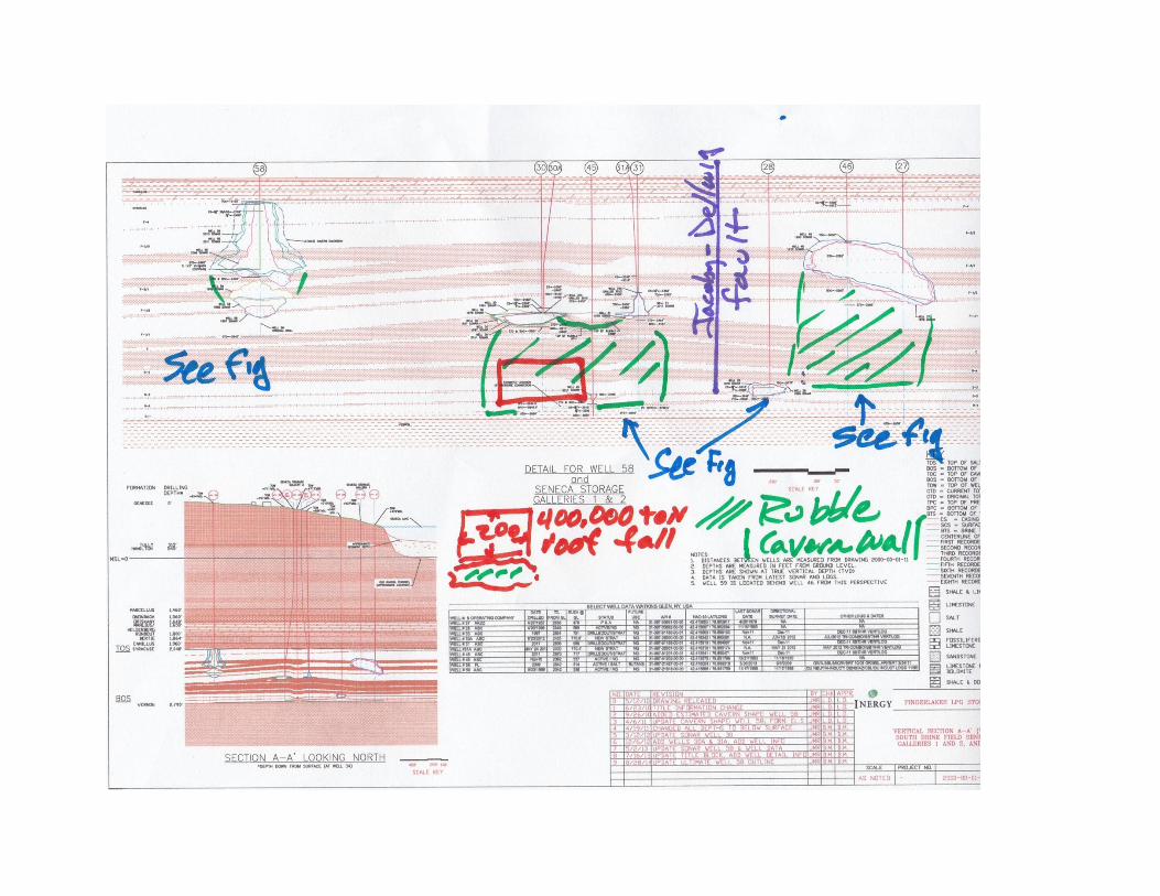
Exhibit C
Marked Cross-Section BB'


Exhibit D
Marked Cross-Section CC'


Exhibit E
Documents Released Pursuant to DEC Freedom of
Information Request


Exhibit F
Curriculum Vitae of H.C. Clark

HCClarkvita1/7 Fall 2014
H.C. Clark
2300 Bolsover
Houston, Texas 77005
Consulting Geology and Geophysics
Rice University [1966-1989], Geology and Geophysics, retired faculty
PhD, Geophysics, Stanford University, 1967
MS, Geophysics, Stanford University, 1966
BS, Geology and Geophysics, University of Oklahoma, 1959
Teaching: courses in geophysics and geology, geologic hazards, engineering geology and geophysics
Research Interests: Current - Geophysical techniques applied to the study of shallow features, geophysical
measurements and hydrogeologic problems, sustainability and agriculture; Past - paleomagnetism,
geophysical measurements and crustal studies, analysis of geologic hazards
Texas Registered Professional Geoscientist 1977.
Municipal Solid Waste and Resource Recovery Advisory Council of the Texas Commission on
Environmental Quality, 2003-2013, representing the Public Director of Student Advising at Rice in 1979
and served in various combinations with Susan Clark until retiring in 1989.
Organizations: American Geophysical Union, Society of Exploration Geophysicists [and Near Surface
Section], Houston Geological Society, Geophysical Society of Houston, Board of Directors-Houston
Urban Gardeners
Consulting Projects
Browning Ferris CECOS Gulf West Hazardous Waste Landfill, Chambers Co., Seismic study of active
fault, groundwater geology
BFI 521 Municipal Landfill, Fort Bend Co., Texas, Geology, groundwater, active faulting and salt dome
BFI McCarty Road Municipal Landfill, Harris Co., Texas, Geology, active faulting
BFI Stratton Ridge Injection Well, Brazoria Co., Texas, Geology, fracture potential
CECOS Livingston Hazardous Waste Landfill, Livingston Parish, Louisiana, Geology
BFI Galveston County Landfill, Galveston Co., Texas , Resistivity study, baseline data
City of Houston, Crystal Chemical Injection Well, Harris Co., Texas, Active faulting, geology of
reservoir
Rice Center for Community Design and Research, Chambers County Natural Factors Study, Chambers
Co., Texas, Geology components
Texas Coast Project, Two County Tier, Texas, Geology components
Metropolitan Transit Authority Project, Harris Co., Texas, Composite fault map metropolitan area
Citizens, Willis, Montgomery Co., Texas, Municipal Landfill, Geology and groundwater
Citizens and County, Matagorda Co., Texas , Phillips 66 Landfarms, Landfills, Contaminated Water
Ponds, Geology, groundwater, systems design
Fayette County Resource Watch, Fayette Co., Texas, Cummins Creek Lignite Mine Geology, geophysics
and groundwater
Citizens, Katy, Texas, CMI Municipal Landfill, Cypress Creek, Geology, faulting
Citizens, East Houston, Texas, Municipal Landfill—Negev, now Bluebonnet, Geology, faulting
Citizens, North Houston, Texas Municipal Landfill—Atascocita, Geology, geophysics
Citizens and Power Systems Equipment, Chappel Hill, Washington Co., Texas Municipal Landfill,
Geology, geophysics, groundwater
CASE, Beaumont-Port Arthur, Jefferson County, Texas, CWMI Injection Well
Campbell, Foss, and Buchannan, Inc. Eureka, Nevada, Mine Exploration
Magnetic measurements and interpretation Norse-Windfall Mines, Eureka, Nevada

HCClarkvita2/7 Fall 2014
Magnetic and seismic refraction measurements and interpretation
Anderson and Frierson, Geologists Central Texas Oil Exploration
Gravity and magnetic measurements and interpretation
U S Army Corps of Engineers, Galveston, Texas Galveston Bay Sand Supply Study
Data compilation and interpretation
U S Air Force, Office of Ballistic Missile Research Micro-blast rapid tunnel excavation. Sunburst
Recovery Seismic recording, CSM Experimental Mine, Golden, Colorado
Tenneco Oil, Exploration and Production, Houston, Texas
Magnetic ranging system for detection of well blowout, patent
Allied Chemical, Norfolk, Virginia, Magnetic survey, steel tank construction site
SanJacinto Development Corp., Landslide and groundwater influence, downstream Livingston Dam; San
Jacinto Co., Texas
Vinson and Elkins, Attorneys, Houston, Fault study. West Houston
Keplinger Associates, Petroleum Engineers, Houston, Oil Mining Study, Ohio, Geophysical
measurements and interpretation Mining Prospect, Alaska, laboratory magnetic measurements and
interpretation
Universal Savings Association, Houston
Hazardous waste study—former pipeline terminal and sludge storage pits
Soil borings, monitor well installation; soil, sludge, groundwater
sampling, interpretation of chemical test results
Hazardous waste study—former manufacturing facility
Waste disposal audit, supervision of testing program
Active surface fault study—former manufacturing complex Field surface study and interpretation
of surface, photo, and subsurface data
Hazardous waste study—office park and landfill area
Soil borings, monitor well installation; soil, sludge, groundwater sampling, interpretation of
chemical test results
ERM Southwest, Houston, Texas, Pesticide Manufacturing Plant, Dallas County, Texas
Seismic refraction interpretation
Testing Unlimited, Houston, Texas, Conroe Jail, Montgomery County, Texas, Seismic study, basement
heave
General Dynamics, Fort Worth, Texas Air Force Plant 4, Fort Worth, Texas, Seismic reflection study,
groundwater problem
McClelland Engineers, Houston, Texas, Bosque Dam Construction Planning, Seismic refraction study,
outlet works
Police Jury, Calcasieu Parish, Louisiana Chemical Waste Management Hazardous Waste Landfill, Lake
Charles Facility-Geologic and hydrologic study
Commissioners Court, Matagorda County, Texas -Phillips 66 Landfarm- geohydrologic study of landfarm
operation
Citizens of Security, Texas-Montgomery County Contractors Type 1 Landfill, geology and
geohydrology—Permit amendment for special wastes
Texas Environmental Coalition, Concerned Citizens of Winona-Land Banned Waste Exemption Petition -
WDW 186, Gibraltar Chemical Resources, Winona, Texas
Citizens, Fort Bend County, Texas-Fort Bend County Landfill - proposed expansion
Resolution Trust Corporation-Former Industrial Facility - ground water contamination
Fault study - seismic reflection profile study-splay faults and contaminant transport
City of League City, Texas-Waste oil processor-Hazardous waste and ground water
Calhoun County Resource Watch, Texas-Union Carbide Plant Hazardous Waste Landfill Faulting,
geology, and ground water; British Petroleum Plant-Hazardous waste landfill geology and performance
Mitchell Development Corporation-Bald Head Island Beach erosion and relationship to Wilmington
Channel Dredging

HCClarkvita3/7 Fall 2014
Allen County [Ohio] Citizens for the Environment Workshop on deep well injection
Louisiana Department of Environmental Quality-Workshop on deep well injection
Law Engineering, Houston, Texas-Workshop on landfills
Citizens, Fort Bend County, Texas-Fort Bend County Landfill - methane migration and groundwater
Citizens, Waco, Texas-City of Waco Landfill Expansion, geological and geophysical analysis
City of Petronila, Nueces County, Texas Texas Ecologists Hazardous Waste Disposal
Analysis of application for two injection wells
Numerous groups in Texas, Louisiana, Ohio: Critical comments on hazardous waste injection wells
including: Gibralter Chemical; Chemical Waste Management, Port Arthur and Corpus Christi, Texas;
Vickery, Ohio; DSI, Empak, Waste Water Inc, Dupont, Celanese, American Cyanamid, Cecos, Rollins,
BP Green Lake, IMC Fertilizer, BP Lima Harris County, Texas-Westbelt Landfill, geological and
geophysical analysis; American Envirotech Hazardous Waste Incinerator, geological and geophysical
analysis
City of Houston and Harris County-Hunter Industrial Facilities salt dome storage of hazardous waste,
geological and geophysical analysis
City of Wilmer, Texas Laidlaw Wilmer Landfill Remand Hearing, geological analysis
Citizens, Lacy-Lakeview (Tirey Trust) Lacy-Lakeview Landfill Expansion, groundwater and geology
CASE-CWMI Port Arthur Landfill-audit of landfill documents-geologic analysis
Citizens, Fairview (COFF), McKinney Landfill Expansion, geological and geophysical analysis
Lower Colorado River Authority-Tricil Landfill, Altair, Texas geological and geophysical analysis
City of Del Rio-CWMI Dryden Landfill, Dryden, Texas
CONTROL [Citizens of Justin, Texas] Sentry Landfill Proposal, Denton, Texas-geological analysis
West Harris County MUDS-Madden Road Landfill geological and geophysical analysis
Sierra Club, Eagle Pass, DOS Republicas Coal Mine, geological and agricultural analysis of alluvial valley
floor
Citizens Live Oak County, Texas IEC Injection Wells 156, 159, geological and geophysical analysis
Citizens Winnsboro, Texas East Texas Landfill, geological analysis
Citizens East Fort Worth, Laidlaw Landfill, MSW 2145, geological analysis
City of Lancaster, Texas WMX Skyline [Ferris] Landfill, 42-C, geological analysis
Citizens Walker County, Texas DDI Landfill, geological analysis
Citizens Palo Pinto County and Fawcett XO Ranches-Blue Flats Landfill, geological analysis
MOSES [Mothers Organized to Stop Environmental Sins] Injection Wells 186 and 229, Smith County,
Texas-injection well, geological and geophysical analysis
Citizen groups Jefferson County NORM facility, geological and geophysical analysis
CCAP Wharton County-Hazardous waste caverns, injection, geology and geophysics
Baggett, McCall & Burgess, Lake Charles PPG Plant contamination plume
ABLE, Canyon, Texas-BFI Canyon Landfill expansion proposal geological analysis
Frost Family Farms, Liberty County Class I [non-hazardous] injection well proposal, geophysical and
geological analysis
Spring Cypress Landfill Coalition, Harris County-Type IV landfill, geology and hydrogeology
Sierra Blanca Legal Defense Fund, Hudspeth County, Texas, Low Level Nuclear Waste Disposal license
application, geophysical analysis
Citizens groups, Kinney County, Adobe Landfill proposal, geophysical and geological analysis
Bill Sutton family, Fort Bend County Long Point Dome landfill, geophysical and geological analysis
North Texas Municipal Utility District 121 Landfill design team, geological and geophysical
measurements
Raytheon [McBride Ratcliff Engineers], Active fault and BMC Software complex, Houston
Limestone County, Texas-Hansen Aggregates quarry design and hydrogeology analysis
Citizens, Hays County, Texas-Aquasource water treatment and discharge facility, geology and
hydrogeology
BFI-Blueridge Landfill expansion, geology and hydrogeology
HCClarkvita4/7 Fall 2014
McFadden Family-Dupont Beaumont no-migration exemption renewals for injection wells, analysis
Frost, FPL Farming Ltd-Amendment to injection well permits WDW316 and 317
Chambers County, TSP Cypress Point Industrial Landfill, geologic issues analysis, industrial rules
analysis
Citizens Fort Bend County, Juliff Type IV Landfill application
Individuals, various LPST and drycleaner contamination cases
BVSMA, Grimes County, landfill application
O'Connor Ranches, Victoria, groundwater resources in South Texas and analysis of issues
BFI-McCarty Landfill expansion
BFI-Blueridge Landfill expansion
State of Nevada, Agency for Nuclear Projects, Yucca Mountain, repository geology and geophysics
Sierra Blanca Ranch, Hudspeth County, quarry site reclamation, geologic issues
Lafitte’s Cove Nature Society, Galveston, comments on hurricane sever potential related to cut and fill
development
Cooke County citizens, Salt Water Disposal well and Barnett Shale operations
Erath County citizens, Salt Water Disposal Well and Barnett Shale operations
Goliad County, geologic hazards and uranium exploration project
TJFA as protestant, Williamson County Landfill Expansion
TJFA as protestant, Comal County Landfill Expansion
Goliad County, UEC uranium mining application opposition
Montgomery County citizens, Type IV Landfill application analysis
Texans For Sound Energy Policy, Victoria nuclear power plant review
Lewisville, Camelot Landfill geology and hydrogeology review
Pescadito Environmental Resource Center, Webb County, Type I landfill application
NoCoal Coalition Matagorda County, White Stallion power plant water well application
Goliad County GCD, UEC uranium mine aquifer exemption discussion
Earthjustice, New York salt cavern storage of LNG and CNG in Watkins Glen brine field FERC
BlackburnCarter, Matagorda County contamination—salt water disposal well[s]
BlackburnCarter, Harris County contamination—gas well/injection well/disposal well
Goliad County citizens—uranium mine aquifer exemption analysis and EPA comments
Quintana LNG Terminal proposal, geologic issues including Stratton Ridge FERC
BlackburnCarter, Bayou Corne, LA, salt cavern collapse and sinkhole
Publications
Keller, M.F., and Clark, H. C. Jr., 1964, Prediction of magnetic anomalies due to four buried spheres, in
Computers In the Mineral Industries, Stanford University Press.
Clark, H. C. Jr., 1966, A Study of a Thick Oligocene Sill as a Paleomagnetic Record of Secular Variation,
(abs.): Trans. Am. Geophys. Un., V.47, p. 79.
Clark, H.C. Jr., 1967, A Fused Quartz Curie-point Balance in Methods in Paleomagnetism, Developments
in Solid Earth Geophysics: Amsterdam, Elsevier Publ. Co., v. 3, pp. 438–439.
Clark, H. C. Jr., 1967, Variation of Remanent Magnetic Properties Related to the Differentiation of the
Mary's Peak Sill, Oregon, (abs): Trans. Am. Geophys. Union, v. 48, p. 79.
Lankford, R. R., Clark, H. C. Jr., Warme, J. E., and Rehkemper, L. J. 1969, Galveston Bay Estuarine
system - Case study in Case Studies of Estuarine Sedimentation and its Relation to Pollution of the
Estuarine Environment: Gulf Universities Research Corporation, Houston, Texas, pp. A-l–A-64.
HCClarkvita5/7 Fall 2014
Gilliland, M. W., Clark H. C. Jr., and Sutler, J. F., 1969, Paleomagnetism of the Buck Hill volcanic series.
Big Bend, Texas (abs.): Trans. Am. Geophys. Un.,V. 50, p. 131.
Clark, H. C. Jr., 1959, Remanent Magnetism, Cooling history, and Paleomagnetic Record of the Mary's
Peak Sill, Oregon: Journal of Geophysical Research, V. 74, ff. 1, pp. 3143-3160.
Clark, H. C. Jr., Flournoy, L. D., and Haupt, L., 1969, Late Pleistocene to Holocene Secular Variation
Observed in Cores from the Gulf of Mexico: Trans. Am. Geophys. Union, V. 50, p. 606.
Clark, H. C. Jr., and Hickcox, A. E., 1970, Remanent magnetic stability and cooling history of the Mary's
Peak Sill, Oregon (Abs.): Bull. Geol. Soc. Am., V 2, p. 276.
Clark, H. C. Jr., and Johnson E. A., 1971, Paleomagnetism of Oaxaca State, Mexico (abs), Trans. Am.
Geophys. Un., V. 52, p. 190.
Clark, H. C. Jr., and Kennett, J. P., 1972, Confirmation of the reality of the Laschamp Geomagnetic
Polarity Event in cores from the Gulf of Mexico (abs.): Trans. Am, Geophys. Un., V. 53, p. 423.
Clark, H. C. Jr., and Kennett, J. P.,1973, Paleomagnetic excursion recorded in Late Pleistocene deep sea
sediments. Gulf of Mexico: Earth and Planetary Science Letters, V. 19, pp. 267-274.
Clark, H. C. Jr,, Fryer, G. E, Gasparini, P., Roberti, N., Scandone, R., 1973, II laboratorio de
paleomagnetismo dell'osservatorio vesuviano: Prod. Associane Geofixica Italiana.
Kennett, J. P., Huddleston, F., Clark, H. C. Jr., 1973, Paleoclimatology, paleomagnetism, and
teprochronology of late Pleistocene sedimentary cores, Gulf of Mexico. In CNRS Symposium Volume:
Les Methodes quantitative d'Estudes des variations du climat au cours du Pleistocene. No. 219, p. 239–
250.
Clark, H. C. Jr, Remanent magnetism of volcanic rocks, 1974, Physical Volcanology (Gasparini, P. and
Civetta, L., Editors), 20 pages, Elsevier. Amsterdam.
Clark, H. C. Jr., and Bradbeer, G. E., 1974, Geology and natural environmental factors. Chambers
County. Texas in Environmental Analysis for Development Planning, Chambers County, Texas. Rice
Center for Community Design and Research and Southwest Center for Urban Research. 28 Manuscript
pages and figures.
Clark, H. C. Jr., 1975, Geology, Map 9 In Texas Gulf Coast Project, Research Report 1, Williams, D. L.,
and Rowe, P.G., ed., Rice Center Community Design and Research, Houston, 261 pages.
Gevirtz, J. L., Clark, H. C. Jr., Rowe P. G., 1975, Environmental Description for Land-Use planning,
Abstracts with Programs, Geological Society of America, Vol. 8, Number l, p. 21.
Clark, H. C. Jr., Georges, D., and Rowe, P. G., 1976, Geologic Hazards and Land Use Planning in the
Gulf Coast, Abstracts with Programs, Geological Society of America, Vol. 8, Number 1, p. 14.
Anderson, J, B., Weaver, M.F., Clark, H. C. Jr., 1977, Sediments and Sedimentary Processes on High
Latitude Continental Shelves, Offshore Technology Conference, V. 9,2738, 8 pages.
Anderson, J. B., and Clark, H. C. Jr, 1977, Geologic Studies for the Galveston County Shore Erosion
Study, U.S. Army Corps of Engineers, Galveston District, 52 pages.

HCClarkvita6/7 Fall 2014
Clark, H. C. Jr., and Gilliland, M. W. 1975, "Paleomagnetism of Early Tertiary Volcanics, Big Bend,
Texas." Cenozoic Geology of the Trans Pecos Volcanic Field of Texas; Conference Proceedings, Alpine,
May 21–25,1978.
Watson, C.W. and Clark, H.C. Jr, 1978, "Gravity measurements and the Big Bend, Texas, as Part of a
Continental Rift." Cenozoic Geology of the Trans Pecos Volcanic Field of Texas; Conference
Proceedings, Alpine, May 21–25, 1978.
Clark, H.C. Jr,1978, Geologic Hazards and Houston, Houston Engineer, May-June, 1978, p. 23–24.
Fainstein. R., and Clark, H.C. Jr., 1975. The Crustal Structure beneath the Victoria-Trinidade Ridge,
Revista Brasileira De Geosciencias, v. 8, p. 170–283.
Metcalfe, C. W. and Clark, H. C. Jr.,1978, Gravity Analysis of the Big Bend, Texas, as part of a
Continental Rift, Abs., Transactions Am. Geoph. Union, V. 59, Number 12, p. 1189.
Gilliland, M. W. and Clark, H. C. Jr., 1979, Paleomagnetism of Early Tertiary Volcanics, Big Bend,
Texas, Guidebook 19, Cenozoic Geology of the Trans-Pecos Volcanic Field of Texas, Anthony W.
Walton and Christopher D. Henry, Texas Bureau of Economic Geology Guidebook Series.
Metcalfe, C. W., and Clark, H. C. Jr., 1979, Gravity Measurements and the Big Bend, Texas, as part of a
Continental Rift," Guidebook 19, Cenozoic Geology of the Trans-Pecos Volcanic Field of Texas,
Anthony W. Walton and Christopher D. Henry, eds., Texas Bureau Of Economic Geology, Guidebook
Series.
Clark, H.C. Jr, and Metcalfe, C. W., 1979, Ouachita Orogenic Belt Offset, Central Texas, ABSTRACT,
Transactions of the American Geophysical Union, V. 60,46.
Clark, H. C. Jr., Greene, L. A. Jr., and Sealy, C. 0., 1979, Ground and Surface Water, Geologic Hazards,
and Waste Disposal: Houston, Texas. ABSTRACT, Trans. Am. Geoph. Union, V. 60,46, p. 230.
Clark, H. C. Jr., and Georges, D., 1981, Deep Well Injection of Liquid Waste: Hazards and Planning,
Abstract, EOS, Transactions of the American Geophysical Union, V, 62, p. 865.
Clark, H. C., 1982, Ouachita Orogenic Complex, Central Texas - Geophysical Measurements and
Basement Offset, Transactions of The Gulf Coast Association of Geological Societies., (M. Malek-
Aslani, ed.), 32, p.157–163.
Clark, H C. Jr., Young, Chapman, Barker, Ronald., 1984, "Field Tests of the Stem-Induced Explosive
Fracturing Technique, Society of Petroleum Engineers of the AIME, Proceedings of the Unconventional
Gas Recovery Symposium, SPE 12840; May 23, 1984, 8 pages.
Young, C., Barker, D., and Clark, H. C., 1986, Field Tests of the Stem Induced Explosive Fracturing
Technique, Society of Petroleum Engineers, Journal of Production Engineering, p. 266–273.
Clark, H.C., 1993, Geophysical Measurements and Environmental Problems in the Regulatory Process,
Special Session, Third International Congress of the Brazilian Geophysical Society, Rio de Janeiro
[Invited Paper].
Clark, H.C., 1995, Geophysical Measurements and the Public Environmental Process [Best of SEG],

HCClarkvita7/7 Fall 2014
American Association of Petroleum Geologists Annual Meeting, p. 17a, Houston.
Clark, H.C., 1996, Overview of Environmental Problems and Non-Invasive Geophysics and Their Role in
the Legal/Regulatory Framework, Looking Into the Earth, Geophysical Society of Houston,
Environmental Applications Special Interest Group, p. 19–20.
Clark, H.C., 2006, Our Bayou City Farmers’ Market; a Public Place, Guide, Urban Harvest, Houston,
Winter, 2006, p. 1–2.
Clark, H.C., 2007, Landscape On The Move, Houston Atlas of Biodiversity, Houston Wilderness, p. 2–4,
Texas A&M University Press, College Station.
Clark, H.C., 2010, Critical Agricultural Strategies from the Outside--In: Approaching Sustainability
Through Doable Farming Centered Enterprise, Gulf Coast Green, Annual Meeting, Houston; also
presented at Houston 2040 and Houston Urban Gardeners.
Clark, H.C., 2011, Is It Time To Re-invent Your Farmers’ Market?, Growing For Market, v. 20, no. 6, p.
2, Fairplain Publishing, Lawrence, Kansas.
Clark, H.C., 2014, Confession of a Weekend Grass Farmer, The Stockman GrassFarmer, March, 2014,
V.14, no. 3, p. 10-14, Mississippi Valley Publishing Co., Ridgeland, MS.
Clark, H.C. and Broussard, M.L., 2014, Houston Rocks, Houston Geological Society Bulletin, v. 59, no.9,
p. 35–39, Houston, TX.
Clark, H.C., 2014, Springfield Spring and Groesbeck’s Water Supply—a cautionary tale for small towns
in Texas, Houston Geological Society Bulletin, v. 57, no.3, p. 17–19, Houston, TX.
Patent: Waters; Robert L. (Austin, TX); Roberts; George F. (Georgetown, TX); Walters; Philip H.
(Austin, TX); Clark; Howard C. (Houston, TX); Fitzgerald; Don D. (Houston, TX); Stelly, II; Otis V.
(Lafayette, LA), 1988, Downhole Combination Tool, 5,064,006 USPO, 1991.