Exhibit 1 - Equipment List - California
22
EXECUTIVE ORDER VR-402-E Morrison Bros. Phase I Enhanced Vapor Recovery (EVR) System For Aboveground Storage Tanks (AST) EXHIBIT 1 Equipment List Equipment Manufacturer/Model Number Emergency Vent (Figures 1A) Morrison 244O WX YYYY AVEVR W represented by: dash (-) = female threads M = male threads F = flange mounted S = with screen X represented by: S = with screen A = Aluminum dash (-) = Blank YYYY represented by: Numerical values between 0 to 9 Male / Female Flanged * Size Setting 0030 2” 16 oz./sq.in. 0060 3” 16 oz./sq.in. 0170 0170 4" 16 oz./sq.in. 0900 5" 16 oz./sq.in. 0200 0050 6" 8 oz./sq.in. 0400 0075 6" 16 oz./sq.in. 0600 0100 8" 8 oz./sq.in. 0700 0200 8" 16 oz./sq.in. 0300 10” 2.5 oz./sq.in. 0400 10” 8 oz./sq.in. 0500 10” 16 oz./sq.in. * Note: For flange mounted models use gasket material made by Fibreflex. More information is available at http://www.fibreflex.com.
Transcript of Exhibit 1 - Equipment List - California

EXECUTIVE ORDER VR-402-E Morrison Bros. Phase I Enhanced Vapor Recovery (EVR) System
For Aboveground Storage Tanks (AST)
EXHIBIT 1 Equipment List
Equipment Manufacturer/Model Number
Emergency Vent (Figures 1A)
Morrison 244O WX YYYY AVEVR W represented by:
dash (-) = female threads M = male threads F = flange mounted S = with screen
X represented by:
S = with screen A = Aluminum dash (-) = Blank
YYYY represented by:
Numerical values between 0 to 9
Male /
Female Flanged* Size Setting 0030 2” 16 oz./sq.in. 0060 3” 16 oz./sq.in. 0170 0170 4" 16 oz./sq.in. 0900 5" 16 oz./sq.in. 0200 0050 6" 8 oz./sq.in. 0400 0075 6" 16 oz./sq.in. 0600 0100 8" 8 oz./sq.in. 0700 0200 8" 16 oz./sq.in.
0300 10” 2.5 oz./sq.in. 0400 10” 8 oz./sq.in. 0500 10” 16 oz./sq.in.
*Note: For flange mounted models use gasket material made
by Fibreflex. More information is available at http://www.fibreflex.com.

VR-402-E - Morrison Phase I EVR System for AST - 2 - EXHIBIT 1
Equipment Manufacturer/Model Number
Overfill Prevention Valve and Drop Tube Assembly Overfill Prevention Valve (Figures 1B)
Drop Tube (Figures 1C)
Morrison 9095W X YYYY – AVEVR W represented by:
A = A Series C = C Series X = X Series
X represented by:
dash = blank V = Nickel Plated A = AA Series or for fuels with S.G. less 0.72
YYYY represented by:
Numerical values between 0 to 9 Size Description 9100 2” Base Model 9200,7200 2” Base Model 9300 3” Base Model 5200 2” Direct Fill 3200 2” Remote Fill 3300 3” Remote Fill 4200,6200,6800 2” Remote Fill
Morrison 419X - -YYZZ 1TEVR X represented by:
dash = Aluminum A = Anodized Aluminum
YY represented by:
Numerical values between 0 to 9 Tube Size 02 2” 03 3”
ZZ represented by:
Numerical values between 0 to 9 As length in Feet

VR-402-E - Morrison Phase I EVR System for AST - 3 - EXHIBIT 1
Equipment Manufacturer/Model Number
Spill Container *
Non-Integral Spill Container* (Figure 1D)
Morrison 516 XX – 0400 ACEVR X represented by:
dash = female threads O = Offset female threads M = male threads MO = Offset male threads
*NOTE: Optional for protected tanks with integral spill container.
Integral Spill Container Convault Drain Valve (Figure 1E) Drain Plug (Figure 1F)
Material: Galvanized, Brass, or Stainless Steel Thread Type: NPT Pipe Fitting
*NOTE: Either is required for protected tanks with integral spill container.
Non-Rotatable Product Adaptor (Figure 1G)
Morrison 927 - - - YYYY AAEVR YYYY represented by:
Numerical values between 0 to 9 Thread Cam & Groove Size Size 0200 2” 2.5” 0300 3” 4” 0400 4” 4”
VR-402-E - Morrison Phase I EVR System for AST - 4 - EXHIBIT 1
Equipment Manufacturer/Model Number
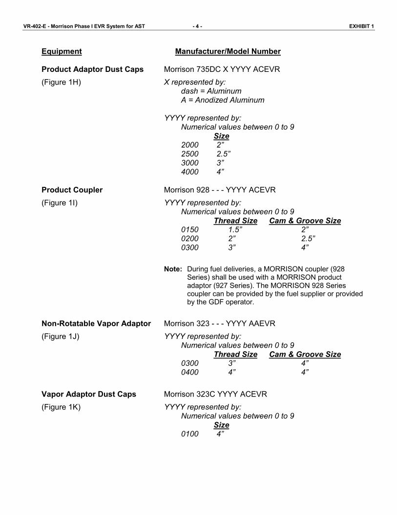
Product Adaptor Dust Caps (Figure 1H)
Product Coupler (Figure 1I)
Non-Rotatable Vapor Adaptor (Figure 1J)
Vapor Adaptor Dust Caps (Figure 1K)
Morrison 735DC X YYYY ACEVR X represented by:
dash = Aluminum A = Anodized Aluminum
YYYY represented by:
Numerical values between 0 to 9 Size 2000 2” 2500 2.5” 3000 3” 4000 4”
Morrison 928 - - - YYYY ACEVR YYYY represented by:
Numerical values between 0 to 9 Thread Size Cam & Groove Size 0150 1.5” 2” 0200 2” 2.5” 0300 3” 4”
Note: During fuel deliveries, a MORRISON coupler (928
Series) shall be used with a MORRISON product adaptor (927 Series). The MORRISON 928 Series coupler can be provided by the fuel supplier or provided by the GDF operator.
Morrison 323 - - - YYYY AAEVR YYYY represented by:
Numerical values between 0 to 9 Thread Size Cam & Groove Size 0300 3” 4” 0400 4” 4”
Morrison 323C YYYY ACEVR YYYY represented by:
Numerical values between 0 to 9 Size 0100 4”

VR-402-E - Morrison Phase I EVR System for AST - 5 - EXHIBIT 1
Equipment Manufacturer/Model Number
Dedicated Gauging Port (Figure 1L)
NOTE: Per CP-206, an Above Ground Storage Tank (AST) shall include a dedicated gauging port for determining the amount of gasoline. The determination shall be accomplished manually, mechanically, or electronically
Gauging Port and Drop Tube Assembly (Optional)
Gauging Port Adapter Morrison 305 X YYYY AAEVR / 305 X YYYY ACEVR X represented by:
blank = Brass Adaptor C = Cap GSP = Cap / Adapter Kit
YYYY represented by:
Numerical values between 0 to 9 Size 0000,2000 2”
Drop Tube (Figures 1C)
Morrison 419X - - YYZZ 1TEVR X represented by:
dash = Aluminum A = Anodized Aluminum
YY represented by:
Numerical values between 0 to 9 Tube Size 02 2”
ZZ represented by:
Numerical values between 0 to 9 As length in Feet

VR-402-E - Morrison Phase I EVR System for AST - 6 - EXHIBIT 1
Equipment Manufacturer/Model Number
Mechanical Tank Gauging (Optional) Morrison Z18 XXX YYYY AGEVR
Z represented by: Numerical values between 8 and 9 8 = Gauge w/o Alarm 9 = Gauge w/ Alarm
X represented by: dash = Male thread C = Custom Clock Face Label (Male Thread) F = Female thread CF = Custom Clock Face Label (Female Thread) MEF = Metric(Female Thread) MET = Metric (Male Thread) DP = Dual Level Points (Male Thread) DPF = Dual Level Points (Female Thread)
YYYY represented by:
Numerical values between 0 to 9 Size Description 0100, 0000 2” with Standard F loat 0400, 2000 2” with Drop Tube Float
Note: Custom clock face label model number. AAABCXXXXXY 2L
AAA = Figure No. = 818 or 918 B = Units of Measure G = Gallons L = Liters C = Shape of Tank

VR-402-E - Morrison Phase I EVR System for AST - 7 - EXHIBIT 1
Equipment Manufacturer/Model Number
Monitoring Cap and Adaptor (Optional)
Morrison 305XXX YYYY ZZEVR XXX represented by:
dash = Brass Adapter XP = Cap with Cable Connector XPA = Cap, Adapter and Cable Connector
YYYY represented by:
Numerical values between 0 to 9 Cap Size Description 2200 2” 3/8” hole & Cable Connector 2400 2” 1/2” hole & Cable Connector 0100 4” 3/8” hole 1100 4” 1/2” hole 0200 4” 3/8” hole & Cable Connector 1200 4” 1/2” hole & Cable Connector Adapter Size Description 0000 2” Adapter 0200 4” Adapter
ZZ represented by:
AA = Adaptor AC = Cap with/without Cable Connector AK = Cap, Adapter with/without Cable Connector
Drop Tube Diffuser (Optional) (Figure 1M)
Morrison 539A XZ YYYY ADEVR X represented by:
S = Slip-on T = Threaded
Z represented by: dash = blank A = Anodized
YYYY represented by:
Numerical values between 0 to 9 Size 0200 2” 0300 3”

TABLE 1-1 Components Exempt from Identification Requirements
Component Name Manufacturer Model Number
419 - - - YYXX 1TEVR Drop Tube Morrison
419A - - YYXX 1TEVR
305 Series Adaptors (dedicated gauging port & Morrison 305 - - - 0000 AAEVR
monitoring cap and adaptor)
Drop Tube Diffuser Morrison 539A Series
Overfill Prevention Valve Morrison 9095 Series
Product Coupler Morrison 928 Series
Double Tapped Bushing Morrison 184 Series
Extractor Morrison 56X Series
VR-402-E - Morrison Phase I EVR System for AST - 8 - EXHIBIT 1
Equipment Manufacturer/Model Number Double Tapped Bushing (Optional) (Figure 1N)
Morrison 184X YYYY1B / 184X YYYYMB X represented by:
blank = iron / steel S = Stainless Steel
YYYY represented by: Numerical values between 0 to 9
Extractor Fitting (Optional) (Figure 1O)
Morrison 56X 0101 MBE X represented by:
Numerical values between 0 to 9

Male Emergency Vents Female Emergency Vents
VR-402-E - Morrison Phase I EVR System for AST - 9 - EXHIBIT 1
FIGURE 1A-1 Morrison Bros. 244 Series Emergency Vents
Flanged Emergency Vents

Vent Sample With Relief Opening Pressure Vent Sample With Relief Opening Pressure Less Than 0.5 Psi Greater Than or Equal to 0.5 Psi
(ONLY APPLIES TO 2" 8OZ/SQ. IN. MODELS)
VR-402-E - Morrison Phase I EVR System for AST - 10 - EXHIBIT 1
FIGURE 1A-2 Morrison Bros. 244 Series Emergency Vents
Cover Marking Diagram
(The X designation will contain a value which may vary depending upon the size and pressure setting of the vent)

Base Model Direct Fill Model Remote Fill Model
(w/o adaptor or bushing) (w/ adaptor) (w/ bushing)
VR-402-E - Morrison Phase I EVR System for AST - 11 - EXHIBIT 1
FIGURE 1B -1 Morrison Bros. 9095A Series Overfill Prevention Valve

Base Model Direct Fill Model Remote Fill Model (w/o adaptor or bushing) (w/ adaptor) (w/ bushing)
VR-402-E - Morrison Phase I EVR System for AST - 12 - EXHIBIT 1
FIGURE 1B-2 Morrison Bros. 9095C Series Overfill Prevention Valve

Base Model Direct Fill Model Remote Fill Model (w/o adaptor or bushing) (w/ adaptor) (w/ bushing)
VR-402-E - Morrison Phase I EVR System for AST - 13 - EXHIBIT 1
FIGURE 1B-3 Morrison Bros. 9095AA Series Overfill Prevention Valve

VR-402-E - Morrison Phase I EVR System for AST - 14 - EXHIBIT 1
FIGURE 1B-3 (con’t) Morrison Bros. 9095 Series Overfill Prevention Valve
9095 AA Series Base Model 9095 X Series Remote Fill Model (w/o adaptor and w/ 2 floats) (w/ bushing and integral seat)

VR-402-E - Morrison Phase I EVR System for AST - 15 - EXHIBIT 1
FIGURE 1C Morrison Bros. 419 Series Drop Tube

FIGURE 1D Morrison Bros. 516 Series Direct Fill Spill Container
VR-402-E - Morrison Phase I EVR System for AST - 16 - EXHIBIT 1
FIGURE 1E FIGURE 1F Convault Drain Valve Drain Plug (Typical)

FIGURE 1G Morrison Bros. 927 Series Non-Rotatable Product Adaptor
VR-402-E - Morrison Phase I EVR System for AST - 17 - EXHIBIT 1
FIGURE 1H Morrison Bros. 735DC Series Product Dust Cap
Note: The number 713 at the bottom of the cap refers to the aluminum the cap is made of, and not the model number of the cap itself.
FIGURE 1I Morrison Bros. 927 Series Non-Rotatable Product Adaptor

VR-402-E - Morrison Phase I EVR System for AST - 18 - EXHIBIT 1
FIGURE 1J Morrison Bros. 323 Series Non-Rotatable Vapor Adaptor
FIGURE 1K Morrison Bros. 323C 0100 ACEVR Vapor Adaptor Dust Cap

VR-402-E - Morrison Phase I EVR System for AST - 19 - EXHIBIT 1
FIGURE 1L Dedicated Gauging Port
NOTE: Per CP-206, an Above Ground Storage Tank (AST) shall include a dedicated gauging port for
determining the amount of gasoline. The determination shall be accomplished manually, mechanically, or electronically
FIGURE 1L-1 Morrison Bros. 305 Series Gauge Port Adaptor and Cap
(optional)
Morrison Bros. 305 Series Gauge Port Adaptor
Morrison Bros. 305 Series Gauge Port Cap

VR-402-E - Morrison Phase I EVR System for AST - 20 - EXHIBIT 1
FIGURE 1L Dedicated Gauging Port
(continue)
FIGURE 1L-2 Morrison Bros. Mechanical Tank Gauge
(optional)
Morrison Bros. 818 Series (optional)
Morrison Bros. 918 Series With Alarm Output
(optional)
Morrison Bros. 918DP Series With Dual Alarm Output
(optional)

VR-402-E - Morrison Phase I EVR System for AST - 21 - EXHIBIT 1
FIGURE 1L Dedicated Gauging Port
(continue)
FIGURE 1L-3 Morrison Bros. 305 Series Monitoring Cap & Adaptor
(optional)

VR-402-E - Morrison Phase I EVR System for AST - 22 - EXHIBIT 1
FIGURE 1M Morrison Bros. 539 Series Drop Tube Diffuser
(optional)
FIGURE 1N FIGURE 1O Morrison Bros. 184 Series Double Morrison Bros. Extractor 56X Series
Tapped Bushing (optional) (optional)
(Photo is of Fig. 562 4” x 4” x 3” x 2”)