Exhaust waste heat recovery Rankine system sizing -...
54
Exhaust Waste Heat Recovery Systems Application to Rankine system HERGOTT Julien 17ème Cycle de conférences Cnam/SIA 15 Mars 2016
Transcript of Exhaust waste heat recovery Rankine system sizing -...

Exhaust Waste Heat Recovery Systems Application to Rankine system
HERGOTT Julien
17ème Cycle de conférences Cnam/SIA 15 Mars 2016

Waste heat recovery technologies
Waste heat recovery potential
Heat to heat systems
Heat to power systems
Focus on Rankine system
Cycle principles
System architectures
Components technologies
System sizing for commercial vehicle application
Design steps
Design point / operating range
Design and constraints variables
Conference agenda
17e cycle conference CNAM/SIA - PARIS - 15/03/2016 2

Waste heat recovery technologies
Waste heat recovery potential
Heat to heat systems
Heat to power systems
Focus on Rankine system
Cycle principles
System architectures
Components technologies
System sizing for commercial vehicle application
Design steps
Design point / operating range
Design and constraints variables
Conference agenda
17e cycle conference CNAM/SIA - PARIS - 15/03/2016 3

Total thermal losses represent 60 to 80 % of fuel energy ! About 30% used to move the vehicle
About 30% used to cool engine cylinder ( maintain material temperature)
About 30% remaining in the exhaust gases (thermal cycle efficiency)
Thermal losses are mandatory and can’t be avoided
Waste Heat Recovery Potential Why do we want to recover heat ?
FECT measurements
1.6L 4Cyl SI Turbo at 100 km/h
The only way to value these losses is to use waste heat recovery systems
17e cycle conference CNAM/SIA - PARIS - 15/03/2016 4
3,3 kW
8%
11,5kW
28%
2,7kW
6% 3,5kW
8%
12,2kW
30%
11,5kW
28%
mechanical
cooling
unbrurnt gases
radiated
exhaust
exhaust condensed
http://energy.gov/eere/vehicles/fact-880-july-6-2015-conventional-vehicle-energy-use-where-does-energy-go

Waste Heat Recovery Potential Exergy analysis
Exhaust exergetic content much higher than coolant
FUEL 100%
To Wheels : 33%
To Exhaust 600C: 15% potential work FUEL 100%
T0 = 20°C
Energy balance Exergy balance
Exhaust energetic content equivalent to coolant
Exhaust gases have the highest potential to produce work !
To Coolant 90C : 5% potential work
Destruction: 47%
17e cycle conference CNAM/SIA - PARIS - 15/03/2016 5
Exergy is amount of energy that can be converted into useful work
Mechanical / electrical work is pure exergy
Thermal energy converted into work has an upper limit: Carnot efficiency
Exergy of heat source depends on its temperature
The higher the temperature, the higher the exergy

Waste Heat Recovery Potential Passenger Cars
Passenger car engine is largely oversized for exceptional but mandatory driving conditions
Engine is mainly used in low efficiency area
Hybrid Electric Vehicles (HEV) partially addresses that issue
It can handles urban usage where there is the lowest efficiency
17e cycle conference CNAM/SIA - PARIS - 15/03/2016 6
4cyl 1.6L turbocharged gasoline
WLTC
Source: internal
Engine speed
En
gin
e T
orq
ue

7
Waste Heat Recovery Potential Passenger Car energy balance
Chemical
6L/100km
18.5 kW thermal
WLTC
Sources : internal
A car is mainly used in transients, especially in urban conditions
Heat to heat can support engine warming and cabin heating.
Regenerative BRAKING • Electric
• Flywheel
• Others (hydraulics)
Heat to Heat • EHRS
• EHRM
1.5L/100km
4.6 kW
1.5 L/100km
4.6 kW
3 L/100km
9 kW
Kinetic energy
0,7 L/100km
Frictions 0,8l/100
High grade Heat
4.6 kW
1.5 L/100km
20% efficient
Where is my money? What could be recovered ? How could it be recovered ? What I paid for
Low grade Heat
9 kW
3 l/100
EXHAUST
EGR
MECHANICAL
COOLING
AND OTHERS
25%
25%
50%
Heat to work • Rankine
• TEG
• Compound
• Air cycles
5-10% thermal efficient = 5-10% fuel eco
< 4 % Efficient = < 8 % FE
17e cycle conference CNAM/SIA - PARIS - 15/03/2016
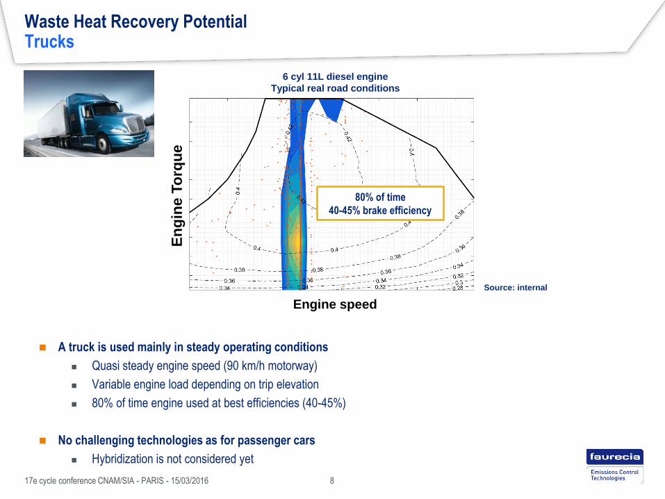
Waste Heat Recovery Potential Trucks
A truck is used mainly in steady operating conditions
Quasi steady engine speed (90 km/h motorway)
Variable engine load depending on trip elevation
80% of time engine used at best efficiencies (40-45%)
No challenging technologies as for passenger cars
Hybridization is not considered yet
8
80% of time
40-45% brake efficiency
6 cyl 11L diesel engine
Typical real road conditions
17e cycle conference CNAM/SIA - PARIS - 15/03/2016
Source: internal
Engine speed
En
gin
e T
orq
ue

9
Waste Heat Recovery Potential Trucks energy balance
13 L/100km
102 kW
7L/100km
55 kW
8 .3 L/100km
66 kW
Aerodynamics
and frictions
11 l/100km
Lost in air
High grade
55 kW
7 L/100km
EXHAUST
EGR
Chemical
30 l/100km
240 kW
thermal
Typical long
haul trip
Sources : internal
CVE usage is mainly steady state. In this mode, hybrid is not able to produce fuel saving.
In this context, Exhaust energy recovery is a promising technology.
Where is it money? What could be recovered ? How could it be recovered ? What my company
paid for ?
Low grade
66 kW
8.3 L/100km
Heat to work • Rankine
• TEG
• Compound
• Air cycles
5-13% thermal efficient = 3 - 8 % Fuel Eco
< 5 % Efficient = < 3 % FE
Kinetic energy 2 L/100km
MECHANICAL
COOLING
AND OTHERS
42.5%
23%
27.5%
17e cycle conference CNAM/SIA - PARIS - 15/03/2016

Waste heat recovery technologies
Waste heat recovery potential
Heat to heat systems
Heat to power systems
Focus on Rankine system
Cycle principles
System architectures
Components technologies
System sizing for commercial vehicle application
Design steps
Design point / operating range
Design and constraints variables
Conference agenda
17e cycle conference CNAM/SIA - PARIS - 15/03/2016 10

Main function is to transfer heat from exhaust to an other fluid (oil or engine coolant)
Heat to heat systems
17e cycle conference CNAM/SIA - PARIS - 15/03/2016 11
Heat to Heat systems
Exhaust gases
Engine coolant
Oil
Indirect fuel economy
• Thermal management (hybrid vehicles)
• Reduce friction (oil heating)
Comfort
• Increase engine coolant heating
𝑄 𝑖𝑛
𝑄 𝑜𝑢𝑡

Heat to heat technologies EHRS
17e cycle conference CNAM/SIA - PARIS - 15/03/2016 12
How it works
• Gas exchange heat with fluid (oil or engine coolant) with heat
exchanger
• Exchanger is bypassed when engine coolant is warm or to
reduce exhaust back pressure at high exhaust mass flow rate
Application
• Hybrid vehicles : Reduces engine utilization to maintain coolant
temperature (thermal management)
• Comfort for winter conditions (faster coolant warm-up)
Exhaust Heat Recovery System
Technology constraints
• Manage exhaust pressure drop
• Avoid fluid boiling
Status : In production
Hyundai IONIQ
Application
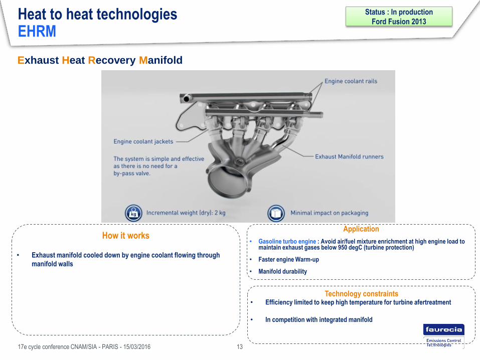
• Gasoline turbo engine : Avoid air/fuel mixture enrichment at high engine load to maintain exhaust gases below 950 degC (turbine protection)
• Faster engine Warm-up
• Manifold durability
Heat to heat technologies EHRM
17e cycle conference CNAM/SIA - PARIS - 15/03/2016 13
How it works
• Exhaust manifold cooled down by engine coolant flowing through
manifold walls
Exhaust Heat Recovery Manifold
Technology constraints • Efficiency limited to keep high temperature for turbine afertreatment
• In competition with integrated manifold
Status : In production
Ford Fusion 2013

Adsorption phase : cabin cooling Desorption phase : heat recovery
Heat to heat technologies Adsorption cycles
17e cycle conference CNAM/SIA - PARIS - 15/03/2016 14
Application • Air conditioning system
• Refrigerated truck
How it works ?
• Cooling cycle without mechanical compressor
• It uses sorbent salt / NH3 saturation properties
• Salt acts as a “thermal” compressor
• Gas pumping when salt is cooled
• Gas discharge when salt is heated
Technology constraints • System duty cycle / Thermal inertia of reactor
• Liquid ammonia safety ?
• Component maturity
Status : Exploration
Cabin
Air
Air exhaust
Air
Cabin

Waste heat recovery technologies
Waste heat recovery potential
Heat to heat systems
Heat to power systems
Focus on Rankine system
Cycle principles
System architectures
Components technologies
System sizing for commercial vehicle application
Design steps
Design point / operating range
Design and constraints variables
Conference agenda
17e cycle conference CNAM/SIA - PARIS - 15/03/2016 15

Heat to power technologies
17e cycle conference CNAM/SIA - PARIS - 15/03/2016 16
Main function is to convert heat into useful power (electrical or mechanical)
Heat to Power
systems
Exhaust gases
Engine coolant
Ambient air
𝑄 𝑖𝑛
𝑄 𝑜𝑢𝑡
𝑊
Direct fuel economy
• Mechanical link to engine crankshaft
Energy storage
• Battery charging (hybrid vehicles)
Comfort • Increase temporarily maximum engine power

Heat to Power technologies TEG
17e cycle conference CNAM/SIA - PARIS - 15/03/2016 17
How it works ?
• Heat exchanger with thermoelectric generators layers between
exhaust gases and engine coolant
• Temperature difference between plates produce electron
circulation = electric current
• Electric production with only one component and no moving
parts !
Thermo Electric Generator
Technology constraints
• Low efficiency with actual materials (<8% thermal efficiency)
• Heat exchanger sizing challenging
• Efficiency requires temperature difference = wall thermal
resistance
• Power requires heat transfer = wall thermal conductance
• Material costs
Exhaust gases
Engine coolant
Status : Innovation ( 2025+)
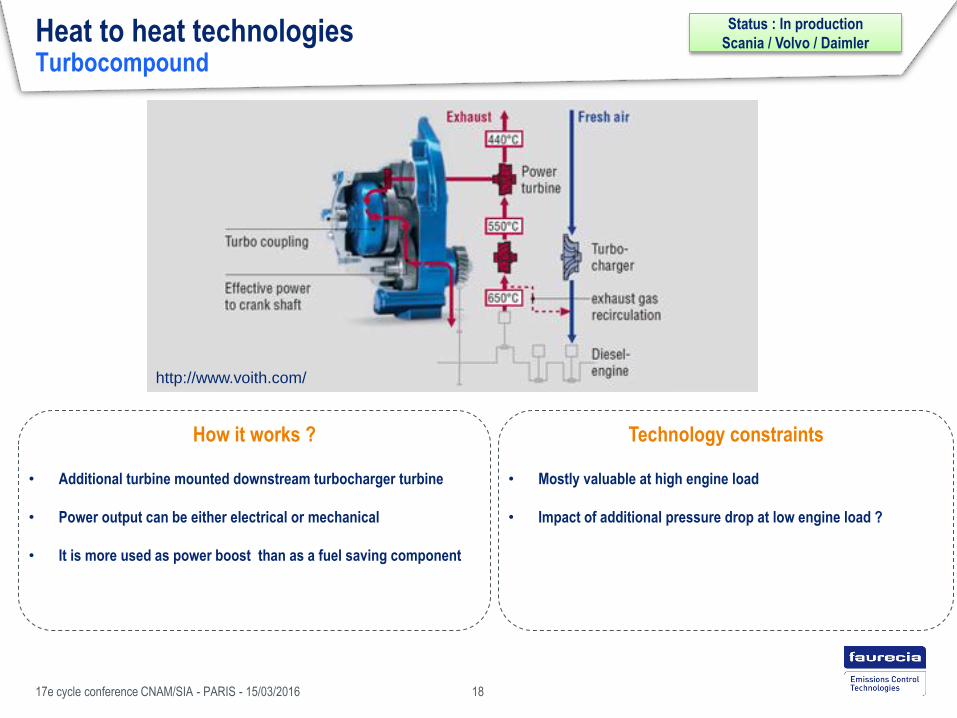
Heat to heat technologies Turbocompound
17e cycle conference CNAM/SIA - PARIS - 15/03/2016 18
How it works ?
• Additional turbine mounted downstream turbocharger turbine
• Power output can be either electrical or mechanical
• It is more used as power boost than as a fuel saving component
Technology constraints
• Mostly valuable at high engine load
• Impact of additional pressure drop at low engine load ?
http://www.voith.com/
Status : In production
Scania / Volvo / Daimler

Heat to power technologies Air cycles
17e cycle conference CNAM/SIA - PARIS - 15/03/2016 19
How it works ?
• Compressor pressurize ambient air and feed an heat exchanger
• Heat exchanger recovers heat from exhaust to increase air
temperature
• Expander expand high temperature/pressure air to recover heat
• Components architecture depends on thermodynamic cycle
• Joules-Brayton
• Stirling
• Ericsson …
Technology constraints
• Work only at high exhaust temperature (>500 degC)
• Compression work
• Air/air heat exchanger = low overall heat transfer
coefficient
• Technology maturity
Joules-Brayton 2 isobaric
2 isentropic
Stirling
2 isochoric
2 isentropic
Heat
exchanger
expander compressor
𝑄 𝑒𝑥𝑎𝑢𝑠𝑡
𝑊 𝑜𝑢𝑡
Ambient air
𝑄 𝑜𝑢𝑡
Status : Exploration
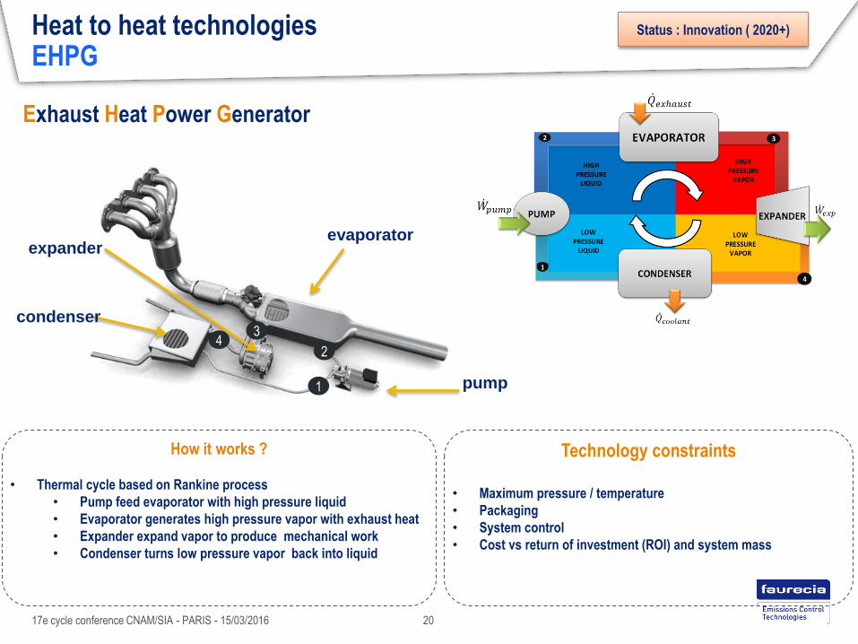
Heat to heat technologies EHPG
17e cycle conference CNAM/SIA - PARIS - 15/03/2016 20
Exhaust Heat Power Generator
How it works ?
• Thermal cycle based on Rankine process
• Pump feed evaporator with high pressure liquid
• Evaporator generates high pressure vapor with exhaust heat
• Expander expand vapor to produce mechanical work
• Condenser turns low pressure vapor back into liquid
Technology constraints
• Maximum pressure / temperature
• Packaging
• System control
• Cost vs return of investment (ROI) and system mass
evaporator
pump
expander
condenser
1
2
3 4
Status : Innovation ( 2020+)

Waste heat recovery technologies
Waste heat recovery potential
Heat to heat systems
Heat to power systems
Focus on Rankine system
Cycle principles
System architectures
Components technologies
System sizing for commercial vehicle application
Design steps
Design point / operating range
Design and constraints variables
Conference agenda
17e cycle conference CNAM/SIA - PARIS - 15/03/2016 21

Waste heat recovery technologies
Waste heat recovery potential
Heat to heat systems
Heat to power systems
Focus on Rankine system
Cycle principles
System architectures
Components technologies
System sizing for commercial vehicle application
Design steps
Design point / operating range
Design and constraints variables
Conference agenda
17e cycle conference CNAM/SIA - PARIS - 15/03/2016 22

Heat Source
10kW
Expander Work
1kW
Heat Sink
9.01 kW
Pump Work
0,01 kW
Electric or
mechanic Electric or
mechanic
Rankine cycle principle Basic layout
𝑄 𝑖𝑛
𝑄 𝑜𝑢𝑡
𝜂𝑡ℎ =𝑊 𝑒𝑥𝑝 −𝑊 𝑝𝑢𝑚𝑝
𝑄 𝑖𝑛
17e cycle conference CNAM/SIA - PARIS - 15/03/2016 23
* Example values

Rankine cycle principle Temperature/Entropy diagram
17e cycle conference CNAM/SIA - PARIS - 15/03/2016 24
Critical point
2 phase region
Supercritical region
Liquid region Superheated Vapor
region
Te
mp
era
ture
[d
eg
C]
• Saturated liquid: liquid ready to boil (any heating lead to vapor bubbles apparition)
• Saturated vapor: vapor ready to condensate (any cooling makes liquid droplets apparition)
Entropy = energy dispersion
Homogeneity = maximum entropy !
T1 T2 T3 T3 time
Low entropy High entropy
𝑻𝟏 > 𝑻𝟑 > 𝑻𝟐
Entropy [kJ/kg/K]

Rankine cycle principle Temperature/Entropy diagram
17e cycle conference CNAM/SIA - PARIS - 15/03/2016 25
This diagram is very useful to asses graphically on cycle performances
Power output calculated with evaporator heat rate
Isobaric
Condensation
Isobaric
evaporation
compression
𝒘𝒊𝒔𝒆𝒏𝒕𝒓𝒐𝒑𝒊𝒄
Expansion
perfect = Isentropic
real
Te
mp
era
ture
[d
eg
C]
Entropy [kJ/kg/K]
Isobaric: constant pressure process
Isothermal: constant temperature process
Isentropic: constant entropy process (ideal)

Rankine cycle principle ideal vs real
17e cycle conference CNAM/SIA - PARIS - 15/03/2016 26
coolant coolant

Waste heat recovery technologies
Waste heat recovery potential
Heat to heat systems
Heat to power systems
Focus on Rankine system
Cycle principles
System architectures
Components technologies
System sizing for commercial vehicle application
Design steps
Design point / operating range
Design and constraints variables
Conference agenda
17e cycle conference CNAM/SIA - PARIS - 15/03/2016 27

System architectures Potential Architectures
exhaust exhaust + EGR
Heat Source
Piston Scroll Turbine
Expander
Screw
Power Output
mechanical electrical
Options
Pressure Vessel Regenerator
Heat Sink
Low temperature
Direct air cooling
High Temperature
Water cooling
Ethanol Organic
Fluid
There is a lot of potential configurations ! 17e cycle conference CNAM/SIA - PARIS - 15/03/2016 28

Depends on OEM engine architecture. EGR trends not clear yet
Not enough exergy on exhaust gases
(system specific power)
For now EGR is not spread on gasoline engine
System Architecture Heat Source selection
Gasoline LV
Exhaust EGR EGR + Exhaust Exhaust EGR EGR + Exhaust
Diesel CVE
Exhaust EGR EGR + Exhaust
Diesel LV
Exhaust gases always used as primary heat source
If available, EGR interest should be valuated with a complete economical study
17e cycle conference CNAM/SIA - PARIS - 15/03/2016 29

High capacity flow Low capacity flow
Condensing pressure is higher with low capacity flow
System Architecture Heat Sink selection
Heat sink characteristics
Capacity flow
𝐶 = 𝑚 × 𝑐𝑝
Temperature
A good heat sink is a sink at low temperature and high capacity flow !
• ability to absorb heat with limited temperature increase
• Low heat capacities can be compensated by mass flow rates
• Cooling potential
• the lower the source temperature, the higher the cooling potential
17e cycle conference CNAM/SIA - PARIS - 15/03/2016 30
𝑻𝒔𝒂𝒕 ↑

Engine coolant Ambient Air
Main circuit Dedicated circuit
Temperature
High
80 to 100 degC
Medium 60 degC
Low − 41 degC in Mouthe (Winter)
40 degC in Toulouse (Summer)
Capacity flow
High
3 – 10 kW / K
Medium To be designed !
Low 0.3 – 1 kW/K for LV
1 – 3 kW / K for CVE
Rankine Architecture Heat Sink selection
Engine coolant circuit is the most stable source in temperature and capacity flow
Coolant loop is designed to absorb heat with limited temperature increase
Care has to be taken to avoid overheating !
Dedicated coolant loop is a good alternative, but others technologies should bring the need
Air as heat sink allows lower temperatures but higher temperature drops !
It also increase inlet temperature of following heat exchanger (AC & Front end radiator)
17e cycle conference CNAM/SIA - PARIS - 15/03/2016 31

System Architecture Energy output
17e cycle conference CNAM/SIA - PARIS - 15/03/2016 32
mechanical
electrical
thermal
Mechanical
• Expander is mechanically plugged to engine
Benefits
• Mechanic to mechanic : high efficiency
Drawbacks
• Live usage : not possible to store energy
• Expander speed linked to engine speed
Electrical
• Expander is plugged to a generator to feed battery
Benefits
• Versatile energy management
• More suitable for high speed expander (turbine )
• Expander speed management
Drawbacks
• Mechanic to electric conversion efficiency
• Battery charge/discharge efficiency
Mechanical vs electrical ?
Rendement mécaniques supérieur mais meilleure gestion de l’énergie
Aucun intérêt electrique si pas d’hybridation
ENGINE
CLUTCH
EHPG ENGINE EHPG
GENERATOR BATTERY

Waste heat recovery technologies
Waste heat recovery potential
Heat to heat systems
Heat to power systems
Focus on Rankine system
Cycle principles
System architectures
Components technologies
System sizing for commercial vehicle application
Design steps
Design point / operating range
Design and constraints variables
Conference agenda
17e cycle conference CNAM/SIA - PARIS - 15/03/2016 33

Components technologies Working fluids
17e cycle conference CNAM/SIA - PARIS - 15/03/2016 34
What is a good working fluid ?
Thermodynamic
properties
SAFETY / ENVIRONEMENT
• Low Flammability
• Low Global Warming potential
COST
• As low as possible
• Material compatibility
THERMODYNAMIC PROPERTIES
• High evaporating pressure
• Low condensing pressure
• Low Pumping work
• Dry expansion
• High Degradation temperature
• Low freezing point
Thermodynamic properties are not the only criterion to select fluid
Dry / wet / isentropic fluids
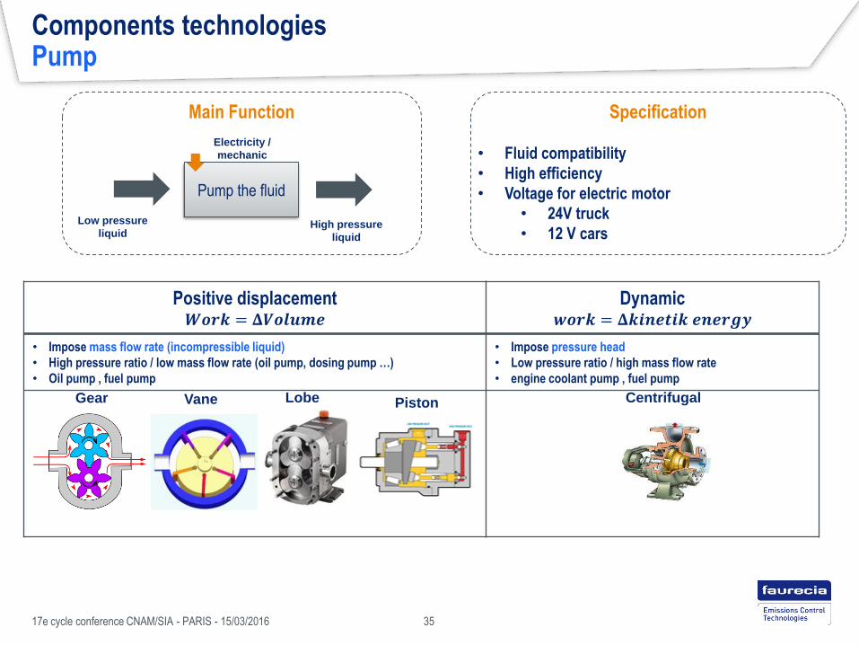
Positive displacement 𝑾𝒐𝒓𝒌 = 𝚫𝑽𝒐𝒍𝒖𝒎𝒆
Dynamic 𝒘𝒐𝒓𝒌 = 𝚫𝒌𝒊𝒏𝒆𝒕𝒊𝒌 𝒆𝒏𝒆𝒓𝒈𝒚
• Impose mass flow rate (incompressible liquid)
• High pressure ratio / low mass flow rate (oil pump, dosing pump …)
• Oil pump , fuel pump
• Impose pressure head
• Low pressure ratio / high mass flow rate
• engine coolant pump , fuel pump
Components technologies Pump
Gear Vane Lobe Centrifugal Piston
Specification
• Fluid compatibility
• High efficiency
• Voltage for electric motor
• 24V truck
• 12 V cars
Main Function
Pump the fluid
Low pressure
liquid High pressure
liquid
Electricity /
mechanic
17e cycle conference CNAM/SIA - PARIS - 15/03/2016 35

Rankine components Evaporator
Preheating zone
Gas / Liquid
Boiling zone
Gas / 2phase
Superheating zone
Gas/ vapor
Fluid out
Gas in
Fluid in
Gas out
Counter flow temperature profile
T
x
wall Gas side
Fluid side
Gas in
Fluid in
Gas out
Fluid out
Counter flow configuration
𝑒𝑓𝑓𝑖𝑐𝑖𝑒𝑛𝑐𝑦 =𝑄
𝑄 𝑚𝑎𝑥
≈𝑇𝑔𝑜𝑢𝑡
− 𝑇𝑔𝑖𝑛𝑇𝑔𝑖𝑛
− 𝑇𝑓𝑖𝑛
• Heat recovery vision: gas as reference for efficiency
• 100% efficiency: gas cooled to fluid inlet temperature
17e cycle conference CNAM/SIA - PARIS - 15/03/2016 36
Pinch Point
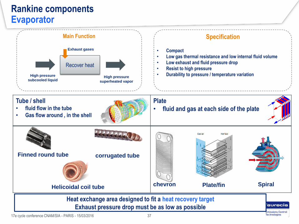
Tube / shell • fluid flow in the tube
• Gas flow around , in the shell
Plate
• fluid and gas at each side of the plate
Rankine components Evaporator
Main Function
Recover heat
High pressure
subcooled liquid High pressure
superheated vapor
Exhaust gases
Specification
• Compact
• Low gas thermal resistance and low internal fluid volume
• Low exhaust and fluid pressure drop
• Resist to high pressure
• Durability to pressure / temperature variation
Finned round tube corrugated tube
Helicoidal coil tube chevron Plate/fin
Heat exchange area designed to fit a heat recovery target
Exhaust pressure drop must be as low as possible
17e cycle conference CNAM/SIA - PARIS - 15/03/2016 37
Spiral

Positive displacement Dynamic
• Work = Volume variation
• Expander absorb volume flow rate in function of expander speed
• Work = kinetic energy variation
• Sonic flow : speed of sound at throat , volume flow independent
of expander speed
Rankine components Expander
Gear Vane Lobe Piston
Specification
• Fluid compatibility
• Compact
• Wet fluid : Accept liquid droplet
• Match pressure and temperature
Main Function
Today, there is no preferred technology for automotive application
Produce
mechanical work
High pressure
superheated vapor Low pressure superheated
vapor or biphasic
17e cycle conference CNAM/SIA - PARIS - 15/03/2016 38

Rankine components Condenser
Main Function
Evacuate heat
Low pressure
Superheated vapor or biphasic Low pressure
subcooled liquid
Heat sink
Specification
• Fluid compatibility
• Compact
• Low pressure drop
• Efficient with low average temperature difference
Same technologies as for evaporator, but not same constraints
Small temperature difference
Low pressure, but has to remains above 1 bar
Technology selection depends on heat sink
Direct air cooling
Low global heat transfer coefficient
Engine coolant High global heat transfer coefficient
Plates Tube/Fins
17e cycle conference CNAM/SIA - PARIS - 15/03/2016 39

Focus on Rankine system Part 2 conclusions
There is a lot of system architectures combinations
Fluids / Expander technologies / Cold source ….
There is no preferred system layout yet
Many compromises to deal with
One or two component technology should be frozen to highlight full architecture
17e cycle conference CNAM/SIA - PARIS - 15/03/2016 40
System design need to be optimized for each OEM architecture and constraints !

Waste heat recovery technologies
Waste heat recovery potential
Heat to heat systems
Heat to power systems
Focus on Rankine system
Cycle principles
System architectures
Components technologies
System sizing for commercial vehicle application
Design steps
Design point / operating range
Design and constraints variables
Conference agenda
17e cycle conference CNAM/SIA - PARIS - 15/03/2016 41

Waste heat recovery technologies
Waste heat recovery potential
Heat to heat systems
Heat to power systems
Focus on Rankine system
Cycle principles
System architectures
Components technologies
System sizing for commercial vehicle application
Design steps
Design point / operating range
Design and constraints variables
Conference agenda
17e cycle conference CNAM/SIA - PARIS - 15/03/2016 42
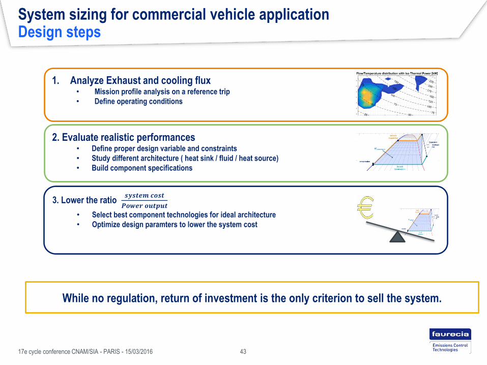
System sizing for commercial vehicle application Design steps
17e cycle conference CNAM/SIA - PARIS - 15/03/2016 43
While no regulation, return of investment is the only criterion to sell the system.
1. Analyze Exhaust and cooling flux • Mission profile analysis on a reference trip
• Define operating conditions
2. Evaluate realistic performances • Define proper design variable and constraints
• Study different architecture ( heat sink / fluid / heat source)
• Build component specifications
3. Lower the ratio 𝒔𝒚𝒔𝒕𝒆𝒎 𝒄𝒐𝒔𝒕
𝑷𝒐𝒘𝒆𝒓 𝒐𝒖𝒕𝒑𝒖𝒕
• Select best component technologies for ideal architecture
• Optimize design paramters to lower the system cost

Waste heat recovery technologies
Waste heat recovery potential
Heat to heat systems
Heat to power systems
Focus on Rankine system
Cycle principles
System architectures
Components technologies
System sizing for commercial vehicle application
Design steps
Design point / operating range
Design and constraints variables
Conference agenda
17e cycle conference CNAM/SIA - PARIS - 15/03/2016 44

System sizing for commercial vehicle application Mission profile analysis
Long haul truck journey selection Vehicle simulation or test
Engine operating range Cooling potential Energy 2D distribution
Mission profile analysis tool
Exhaust available heat
Engine performances
Exhaust flow , temp
Cooling performances
Exhaust and cooling flow/ temperature for operating range
17e cycle conference CNAM/SIA - PARIS - 15/03/2016 45
Engine data

System sizing for commercial vehicle application
Operating range
17e cycle conference CNAM/SIA - PARIS - 15/03/2016 46
Evaporating pressure variation
• Boiling Pressure: proportional to boiler heat
• Fixing nominal pressure will fix pressure operating range
Cooling capacity
Without fan
Rejected
by engine
Available for
condenser
Cooling capacity
Without fan
Rejected
by engine
Available for
condenser
System operating range
Cooling limit Min expander
pressure
Exhaust available power range
Maximum cooling capacity
Low vehicle speed / high
engine load 𝑸 𝒃𝒐𝒊𝒍
𝑷𝒃𝒐𝒊𝒍
𝑷𝒎𝒊𝒏
𝑷𝒎𝒂𝒙
Nominal speed and load
Max pressure limit
Design 1
Design 2
Impacted by evaporating pressure variation and cooling capacity
Min Max
Waste heat recovery technologies
Waste heat recovery potential
Heat to heat systems
Heat to power systems
Focus on Rankine system
Cycle principles
System architectures
Components technologies
System sizing for commercial vehicle application
Design steps
Design point / operating range
Design and constraints variables
Conference agenda
17e cycle conference CNAM/SIA - PARIS - 15/03/2016 47

System sizing for commercial vehicle application Performances prediction / Component specifications
What are the design variables and constraints ?
Design variables Variable that define system performances
Design Constraints Upper / Lower limits to design a realistic system
A good knowledge of system is required to define constraints
Realistic constraints = appropriate design variables = realistic components specs
Evaporating pressure , fluid super heat…. Max pressure, min pressure, subcool ….
Thermo Analysis tool
Performances/
Component spec
17e cycle conference CNAM/SIA - PARIS - 15/03/2016 48

Design variable and constraints Evaporating pressure
17e cycle conference CNAM/SIA - PARIS - 15/03/2016 49
The highest pressure is often not the optimal design in term of cost
Design point pressure define system operating range !
Effect of evaporating pressure increase
• Increase net isentropic work
• Increase required boiler heat transfer area
• Can reduce max recoverable work (pinch location)
• Increase pumping work
Constraints
• Has to remains bellow max allowable pressure
• Expander matching

Design variable and constraints Fluid superheating
17e cycle conference CNAM/SIA - PARIS - 15/03/2016 50
Effect of fluid superheat increase
• Increase net isentropic work
• Avoid droplet formations of wet fluid during expansion
• Increase required boiler area
Constraints
• Fluid outlet temperature bellow degradation temperature
• Minimum superheat for wet fluids and turbine
Fluid superheat is costly in term of boiler area for limited power output increase due to mass flow decrease
Superheat will be kept at a minimum level (10-20 K for dry fluids / 30-50 K for wet fluids)
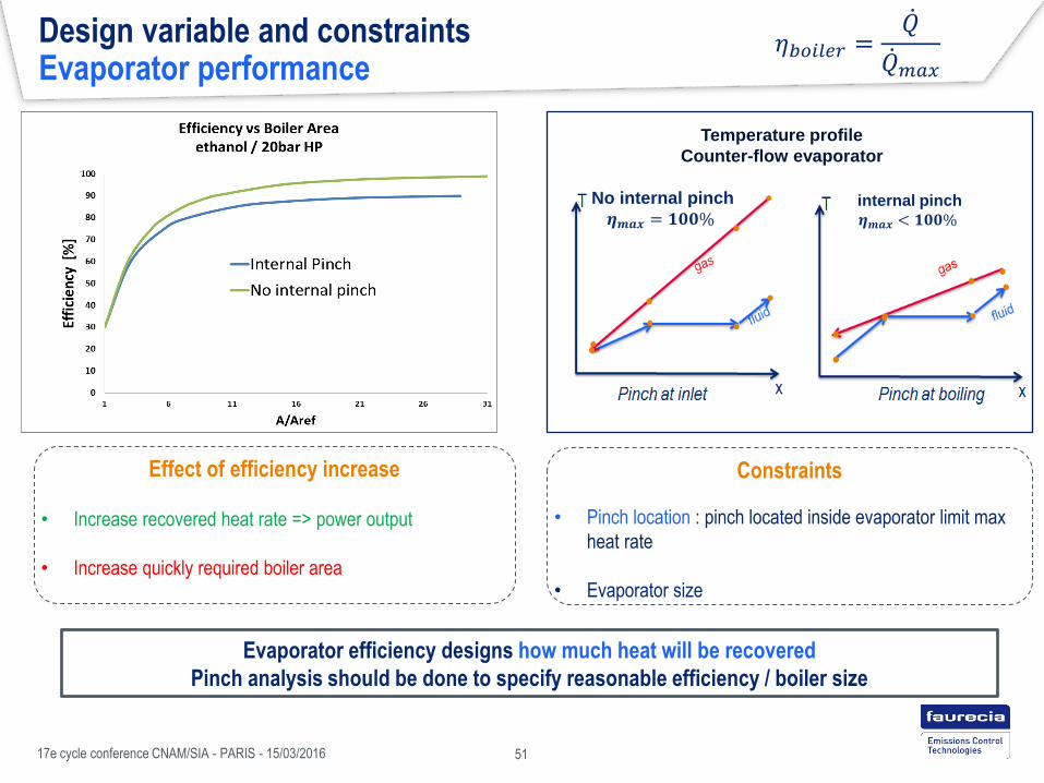
Design variable and constraints Evaporator performance
17e cycle conference CNAM/SIA - PARIS - 15/03/2016 51
Effect of efficiency increase
• Increase recovered heat rate => power output
• Increase quickly required boiler area
Constraints
• Pinch location : pinch located inside evaporator limit max
heat rate
• Evaporator size
Evaporator efficiency designs how much heat will be recovered
Pinch analysis should be done to specify reasonable efficiency / boiler size
No internal pinch
𝜼𝒎𝒂𝒙 = 𝟏𝟎𝟎% internal pinch
𝜼𝒎𝒂𝒙 < 𝟏𝟎𝟎%
Temperature profile
Counter-flow evaporator
𝜂𝑏𝑜𝑖𝑙𝑒𝑟 =𝑄
𝑄 𝑚𝑎𝑥
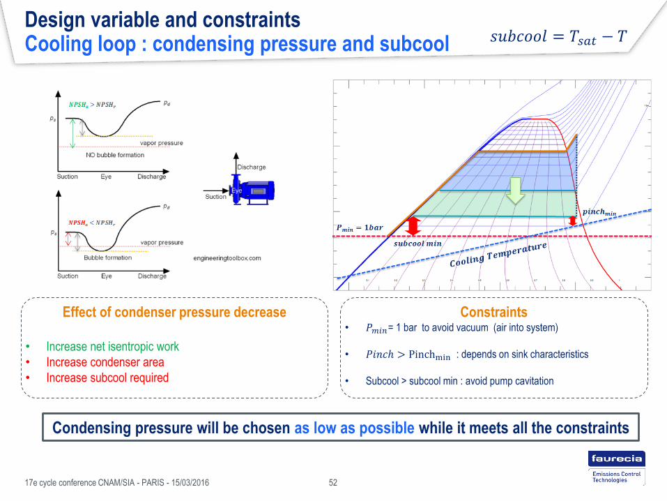
Design variable and constraints Cooling loop : condensing pressure and subcool
17e cycle conference CNAM/SIA - PARIS - 15/03/2016 52
Effect of condenser pressure decrease
• Increase net isentropic work
• Increase condenser area
• Increase subcool required
Constraints • 𝑃𝑚𝑖𝑛= 1 bar to avoid vacuum (air into system)
• 𝑃𝑖𝑛𝑐ℎ > Pinchmin : depends on sink characteristics
• Subcool > subcool min : avoid pump cavitation
Condensing pressure will be chosen as low as possible while it meets all the constraints
𝑠𝑢𝑏𝑐𝑜𝑜𝑙 = 𝑇𝑠𝑎𝑡 − 𝑇

Design variable and constraints Design variable / constraints summary
17e cycle conference CNAM/SIA - PARIS - 15/03/2016 53
With all the constraints, design area is limited.
Optimization work can begin …

General conclusion
Design of Rankine system is challenging, but has the highest short term fuel
economy potential for trucks
Faurecia as technical solutions supplier, wants to supply a full system
System design
Component selection
control
Faurecia develops engineering tools to study such system and support
development and technical assessment
Simulation
Test bench
Next steps : demonstration system !
17e cycle conference CNAM/SIA - PARIS - 15/03/2016 54