Exhaust Gas Attemperator (EGA)
12
Intern © Siemens AG 2014 Alle Rechte vorbehalten. Jan. 2015 / PG ES EN SFCS SG Exhaust Gas Attemperator (EGA)
Transcript of Exhaust Gas Attemperator (EGA)

Intern © Siemens AG 2014 Alle Rechte vorbehalten. Jan. 2015 / PG ES EN SFCS SG
Exhaust Gas Attemperator (EGA)

Jan. 2015
Intern © Siemens AG 2014 Alle Rechte vorbehalten.
Seite 2 Bauer / SFCS SG
Basic Requirements, external Partners
• GT upgrades leads partial to increased exhaust gas temperatures
• Part load ATK increase for GT operation with restrictive CO limits
• HRSG limits for duct system (design report)
External Partners: • TEC artec valves GmbH&Co. KG Oranienburg (supplier injection system) • CFX Berlin (CFD analysis)

Jan. 2015
Intern © Siemens AG 2014 Alle Rechte vorbehalten.
Seite 3 Bauer / SFCS SG
System Overview
spray water for GT exhaust gas attemperators
Exhaust
Feed Water Pump
Heat Recovery Steam Generator Condensate Preheater
Main Condensate Pump
GT Exhaust Gas
attemperator cooling water return
attemperator cooling water supply
Spray Water Pumps
Option: Pressure
Regulator
8 spraywater attemperators
which are arranged in one cross section around the GT exhaust gas duct
M
to Aux. Cooling Water PGB DN25
0 – 0,2 kg/s
DN
15
DN
15
DN
15
DN
15
DN80
0 – 12 kg/s
DN40
0 – 1,5 kg/s
from Aux. Cooling Water PGB
Option: Pressurized Water Storage Tank DN40
0 – 1,5 kg/s Option: Safety
Valve
DN25
0 – 0,2 kg/s
M
M
M
GHC

Jan. 2015
Intern © Siemens AG 2014 Alle Rechte vorbehalten.
Seite 4 Bauer / SFCS SG
General Data for Attemperator Design and Check of Capacity of involved Components
Design Data Attemperator: Deionat consumption base load, dt = 30 K m = 5,9 kg/s - „ - part load, dt = 30 K m = 3,6 kg/s - „ - „Cold Start stationary conditions“ m = 6 - 8 kg/s Design Value m = 12 kg/s p min deionat (according to manufacturer) p = 20 bar pump design dp = 30 bar Main involved BoP Components: Deionat Production System Capacity (GC) m = 2 x 1,11 kg/s Deionat Storage Tank (GHC) V = 600 m³

Jan. 2015
Intern © Siemens AG 2014 Alle Rechte vorbehalten.
Seite 5 Bauer / SFCS SG
Arrangement of Components and Systems
Jan. 2015
Intern © Siemens AG 2014 Alle Rechte vorbehalten.
Seite 6 Bauer / SFCS SG
CFD Analysis
Different Parameters to be checked: • Number of injection points • Distance of injection point to inliner plate • Droplet diameters • Spray angle and direction • Droplet velocity • Injection mass flow • Flue gas velocity and temperature distritution (GT) • Base load and part load conditions (GT)

Jan. 2015
Intern © Siemens AG 2014 Alle Rechte vorbehalten.
Seite 7 Bauer / SFCS SG
Detailled Arrangemant of Attemperator Lances at Exhaust Gas Diffuser
Jan. 2015
Intern © Siemens AG 2014 Alle Rechte vorbehalten.
Seite 8 Bauer / SFCS SG
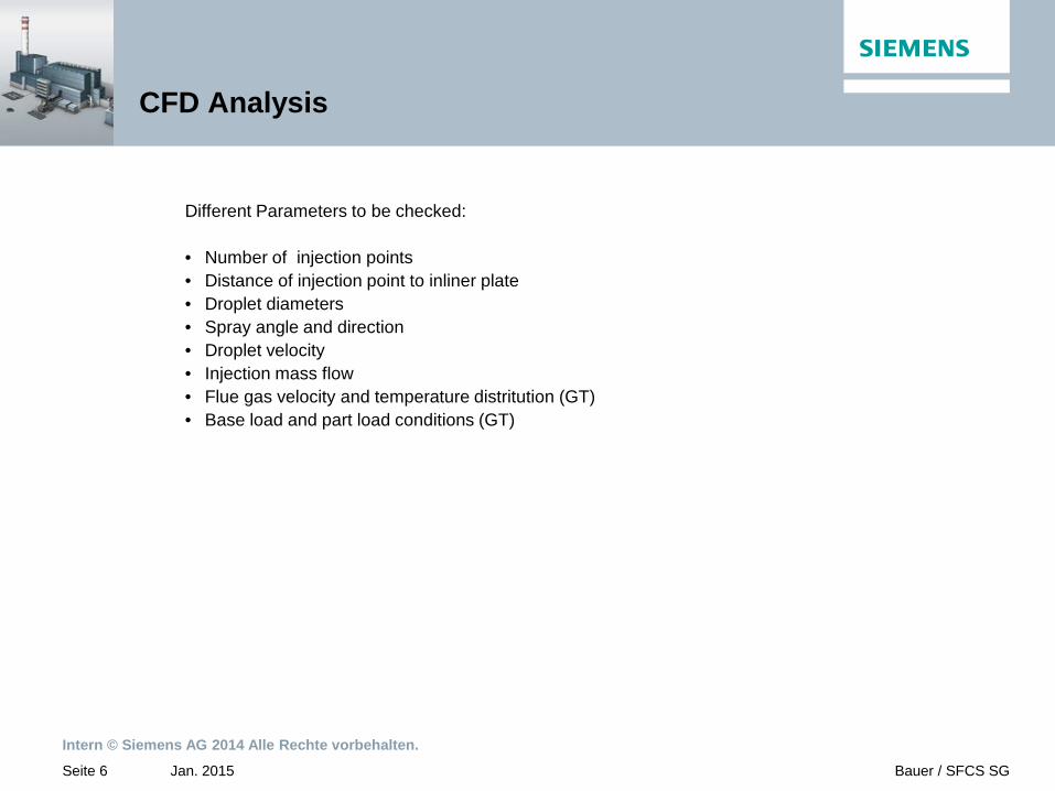
Details of Attemperator Lances

Jan. 2015
Intern © Siemens AG 2014 Alle Rechte vorbehalten.
Seite 9 Bauer / SFCS SG
Arrangement draft

Jan. 2015
Intern © Siemens AG 2014 Alle Rechte vorbehalten.
Seite 10 Bauer / SFCS SG
Control Valve

Jan. 2015
Intern © Siemens AG 2014 Alle Rechte vorbehalten.
Seite 11 Bauer / SFCS SG
Implementation Checklist
• Check of − Water consuption acceptable for customer? − Thermodynamik of HRSG (only for „cold start on the fly“ procedure) − Capacity of bypass stations (HP, IP,LP) (only for „cold start on the fly“ procedure) − Arrangement and routing of deionat system LCE90 and closed cooling water system PGB30/40 − Design parameter of deionat system (capacity of deionat production, storage, transporation system) − Evaluation of life time consumption of HRSG pressure parts (only for „fast cold start “ procedure)
• Engineering − Plant layout for additional systems and components − Routing for deionat and cooling water piping − Modification of GT diffuser (drilling, fittings) − Erection sequences − Ordering of components, piping, erection etc. − Commissioning − Testing

Jan. 2015
Intern © Siemens AG 2014 Alle Rechte vorbehalten.
Seite 12 Bauer / SFCS SG
Main Business Case (Fast Cold Start Up GT)
P MW
Time
GT baseload or frequent operation
GT partload operation (IGV min)
Low partload operation of GT (TT2 390 C)
ST in operation
Additional electrical power output during start up procedure
35-45 min 2-2,5 h
ST warm up procedure
20
120
240
0
50