EXHAUST AFTERTREATMENT IN THE FRAMEWORK … · EXHAUST AFTERTREATMENT IN THE FRAMEWORK OF SYSTEM...
29
15/06/2011 EXHAUST AFTERTREATMENT IN THE FRAMEWORK OF SYSTEM ENGINEERING SIMULATION Johann C. Wurzenberger, Sophie Bardubitzki (AVL List GmbH) Roman Heinzle (Industrial Mathematics Competence Center, MathConsult GmbH) Tomaž Katrašnik (University of Ljubljana)
Transcript of EXHAUST AFTERTREATMENT IN THE FRAMEWORK … · EXHAUST AFTERTREATMENT IN THE FRAMEWORK OF SYSTEM...
15/06/2011
EXHAUST AFTERTREATMENT IN THE FRAMEWORK OF SYSTEM ENGINEERING SIMULATION
Johann C. Wurzenberger, Sophie Bardubitzki (AVL List GmbH)
Roman Heinzle (Industrial Mathematics Competence Center, MathConsult GmbH)
Tomaž Katrašnik (University of Ljubljana)
2CLEERS 2013 | University of Michigan | April 2013 | J.C. Wurzenberger
OVERVIEW
� System Engineering Simulation
� Requirements
� Functionalities
� Simulation Examples
� TGDI Engine in Hybrid Passenger Car
� HSDI Diesel Engine in Conventional Passenger Car
� Summary/Conclusions

3CLEERS 2013 | University of Michigan | April 2013 | J.C. Wurzenberger
REQUIREMENTS ON SYSTEM ENGINEERING SIMULATION SUPPORTING AND CONCEPT DESIGN AND CALIBRATION
� Multi-physical system simulation� Dedicated models and solvers for all
vehicle domains (engine, cooling, drivetrain, e-
system)
� Consistent plant modelling � Links development teams from concept to
calibration phase
� Scalable physical modelling depth� Right balance of predictability and CPU
speed
� Flexible model customization� Best combination of standard and custom
models
� Open interface in office and HiL� Office co-simulation platform and model
export on all relevant HiL systems
� From engineering to commercial
tools� Experience of powertrain engineering as
input for tool development

4CLEERS 2013 | University of Michigan | April 2013 | J.C. Wurzenberger
MULTI-PHYSICS SYSTEM SIMULATIONENGINE, COOLING, VEHICLE AND CONTROL
Cooling & Lubrication
(dt~1000ms)
Quasi-State/Transient Flow
Transient Energy Balance
Air Path, Control,
Vehicle
Drivetrain
(dt~0.5-5ms)
Electric
Quasi-State
Aftertreatment
(dt~arbitrary)
Stiff systems
Cylinder
(dt~1degCRA,
speed dependent)
5CLEERS 2013 | University of Michigan | April 2013 | J.C. Wurzenberger
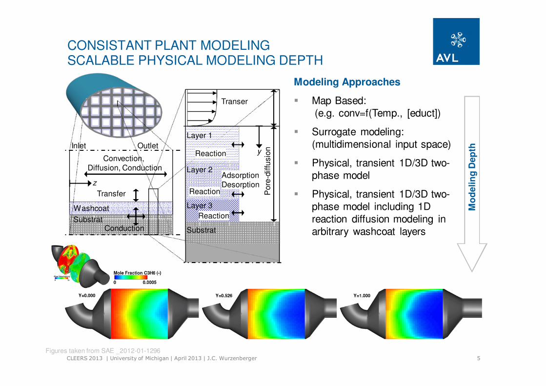
CONSISTANT PLANT MODELINGSCALABLE PHYSICAL MODELING DEPTH
Convection,
Diffusion, Conduction
Inlet Outlet
Transfer
Washcoat
SubstratConduction Substrat
Layer 3
Layer 2
Layer 1
Po
re-d
iffu
sio
n
Adsorption
Desorption
Transer
Reaction
Reaction
Reaction
z
y
Modeling Approaches
� Map Based:
(e.g. conv=f(Temp., [educt])
� Surrogate modeling:
(multidimensional input space)
� Physical, transient 1D/3D two-
phase model
� Physical, transient 1D/3D two-
phase model including 1D
reaction diffusion modeling in
arbitrary washcoat layers
Figures taken from SAE _2012-01-1296
Mo
delin
g D
ep
th
6CLEERS 2013 | University of Michigan | April 2013 | J.C. Wurzenberger
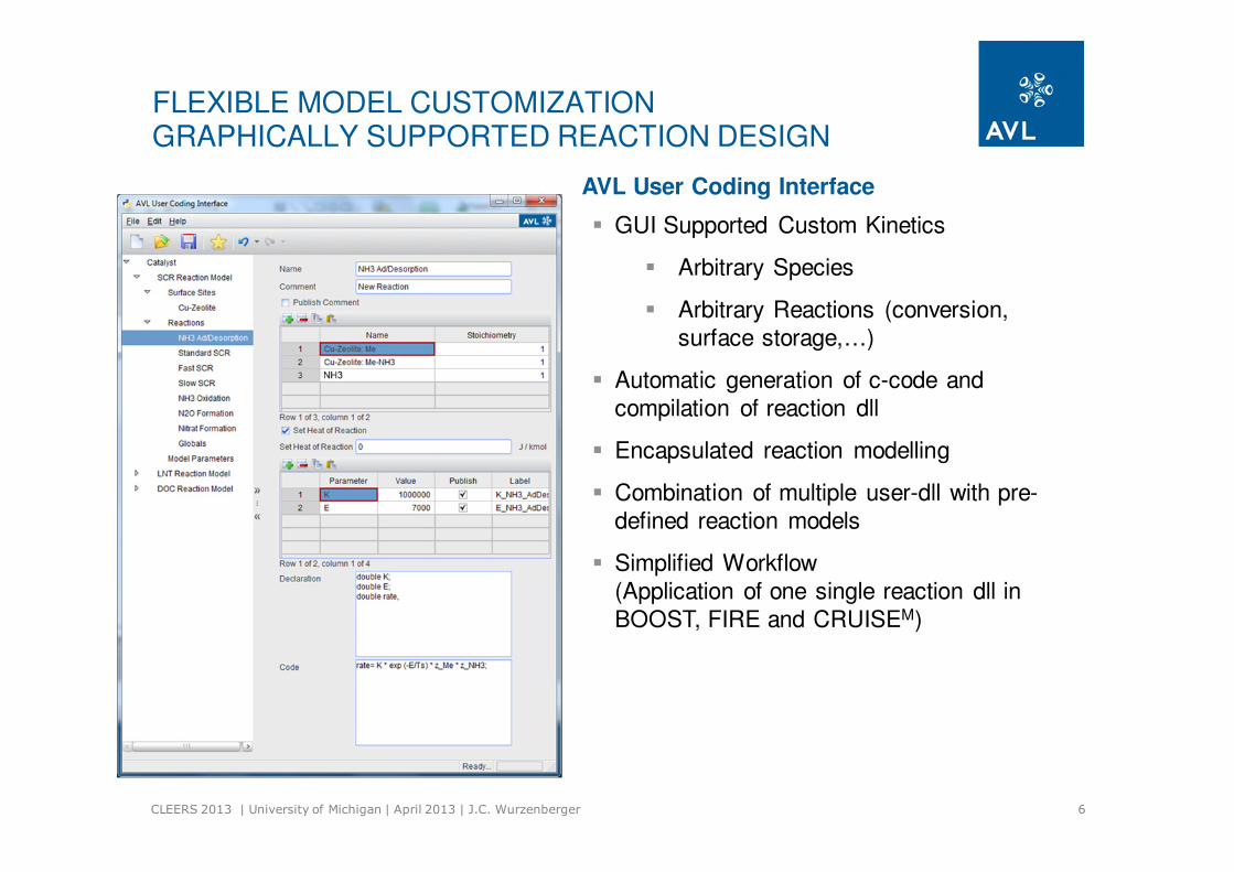
� GUI Supported Custom Kinetics
� Arbitrary Species
� Arbitrary Reactions (conversion,
surface storage,…)
� Automatic generation of c-code and
compilation of reaction dll
� Encapsulated reaction modelling
� Combination of multiple user-dll with pre-
defined reaction models
� Simplified Workflow
(Application of one single reaction dll in
BOOST, FIRE and CRUISEM)
FLEXIBLE MODEL CUSTOMIZATIONGRAPHICALLY SUPPORTED REACTION DESIGN
AVL User Coding Interface

7CLEERS 2013 | University of Michigan | April 2013 | J.C. Wurzenberger
Model
(R1) urea → NH4+ + NCO-
(R2) NH4+ → NH3(g) + H+
(R3) NCO- + H+ → HNCO(g)
(R4) urea + NCO- + H+ → biuret
(R5) biuret → urea + NCO- + H+
(R6) biuret + NCO- + H+ → cyanuric acid + NH3(g)
(R7) cyanuric acid → 3 NCO- + 3 H+
(R8) cyanuric acid + NCO- + H+ → ammelide + CO2(g)
(R9) ammelide → 2 NCO- + 2 H+ + HCN(g) + NH(g)
(R10) urea(aq) → NH4+ + NCO-
(R11) NCO- + H+ + H2O(aq) → NH3(g)+ CO2(g)
(R12) urea(aq) + NCO- + H+ → biuret
12 reactions
F
F
FD
D
D
F
F: formation reactionD: decomposition reaction
urea
CH4N2Obiuret
C2H5N3O2
cyanuric acid
C3H3N3O3
ammelide
C3H4N4O2
FLEXIBLE MODEL CUSTOMIZATIONEXAMPLE: UREA DECOMPOSITION APPROACH
( )∏ ∑∑
−
⋅⋅Γ⋅⋅
−⋅=
j j
j
k
k
init
kjj
s
A ZvZT
TeAr νσ 1^1000/^^'&
Ebrahimian, V.: “Development of multi-component evaporation models and 3D modeling of NOx-SCR reduction
system”, PhD thesis, L‘Universitè de Toulouse, 2011
8CLEERS 2013 | University of Michigan | April 2013 | J.C. Wurzenberger
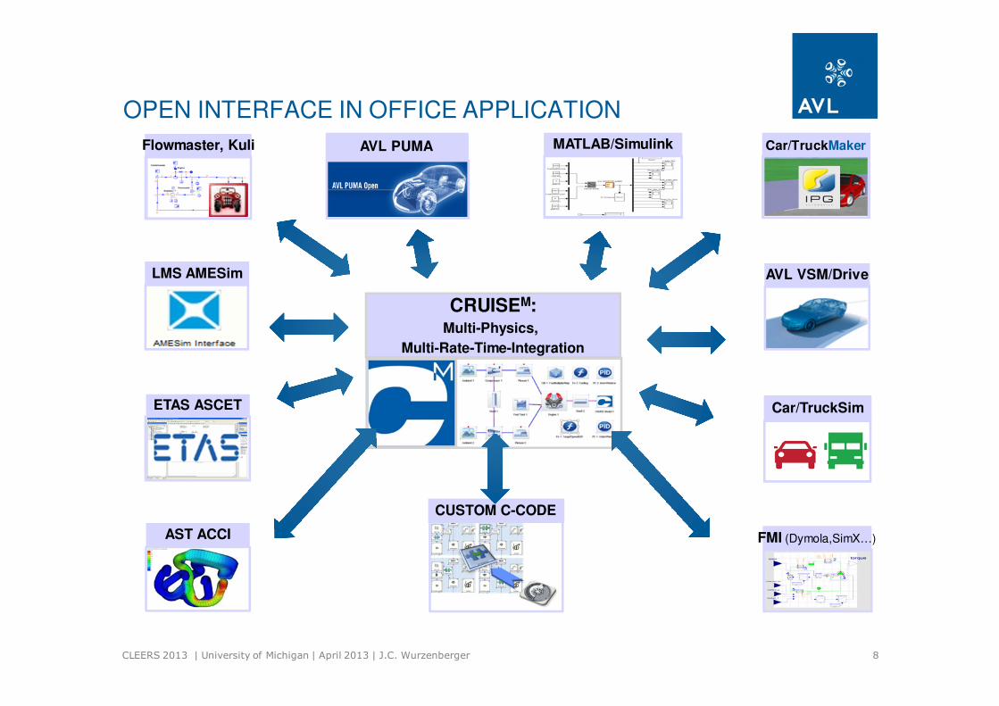
MATLAB/SimulinkFlowmaster, Kuli
Car/TruckSim
AVL VSM/DriveLMS AMESim
FMI (Dymola,SimX…)
ETAS ASCET
AST ACCI
Car/TruckMakerAVL PUMA
CRUISEM:Multi-Physics,
Multi-Rate-Time-Integration
CUSTOM C-CODE
OPEN INTERFACE IN OFFICE APPLICATION

9CLEERS 2013 | University of Michigan | April 2013 | J.C. Wurzenberger
OPEN INTERFACE IN HIL APPLICATION
InMotionInMotion
Car/TruckMakerCar/TruckMaker

10CLEERS 2013 | University of Michigan | April 2013 | J.C. Wurzenberger
Mission compilation out of various
sources
� Radom-cycle generator:
Compile random driving profile out from 20000 short trips
� In-Use data import: Load GPS (e.g. measured via
M.O.V.E., NAVTEC)
� Legislation cycles:Selection of driving profile from
built-in library
� Combine individual task to
dedicated mission
Mission Model
Emission
Random Cycle Generator
M.O.V.E.
Legislation Cycle
REAL-LIFE EMISSIONS IN OFFICE SIMULATION
11CLEERS 2013 | University of Michigan | April 2013 | J.C. Wurzenberger
OVERVIEW
� System Engineering Simulation
� Requirements
� Functionalities
� Simulation Examples
� TGDI Engine in Hybrid Passenger Car
� HSDI Diesel Engine in Conventional Passenger Car
� Summary/Conclusions
12CLEERS 2013 | University of Michigan | April 2013 | J.C. Wurzenberger
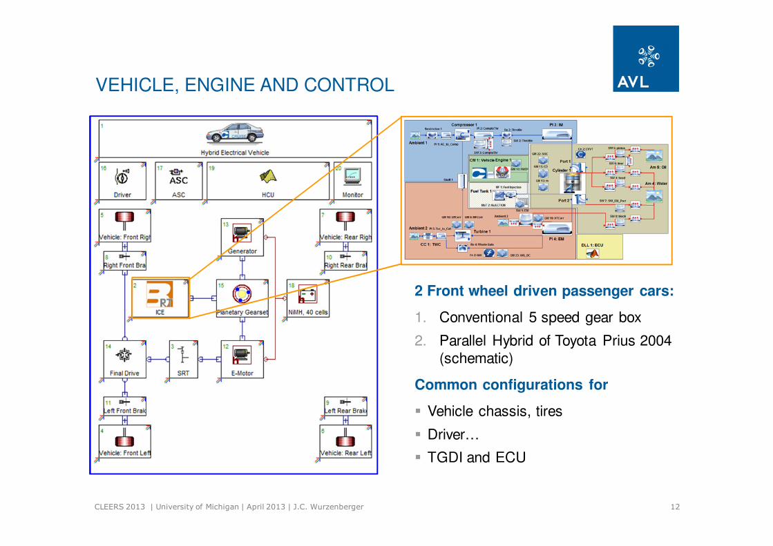
VEHICLE, ENGINE AND CONTROL
2 Front wheel driven passenger cars:
1. Conventional 5 speed gear box
2. Parallel Hybrid of Toyota Prius 2004
(schematic)
Common configurations for
� Vehicle chassis, tires
� Driver…
� TGDI and ECU
13CLEERS 2013 | University of Michigan | April 2013 | J.C. Wurzenberger
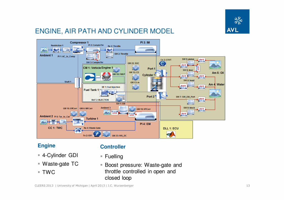
ENGINE, AIR PATH AND CYLINDER MODEL
Engine
� 4-Cylinder GDI
� Waste-gate TC
� TWC
Controller
� Fuelling
� Boost pressure: Waste-gate and
throttle controlled in open and
closed loop

14CLEERS 2013 | University of Michigan | April 2013 | J.C. Wurzenberger
CYLINDER, COMBUSTION AND POLLUTANT FORMATION
Model Characteristics:
� Air path (IM, EM, Walls, TC, Air Cleaner,
Intercooler, Fuel Tank, Catalysts etc.)
elements are descripted in time domain by
1. Mean Value approach (this study)
2. Filling/Emptying approach
� Cylinder, ports, wall heat transfer, injector,
etc. are described in crank angle domain
� Single zone during gas exchange
� Two zone during high pressure phase
� Combustion is modeled by GCA derived
maps for Vibe parameters
� Pollutant Formation is modeled by
surrogates taking advantage of the
crank resolved cylinder (in particular in-
cylinder A/F ratio)
� Port and Cylinder heat losses following
Zapf and Wimmer
Mass / Species Conservation
Energy Conservation

15CLEERS 2013 | University of Michigan | April 2013 | J.C. Wurzenberger
NO FORMATION
Model Characteristics:
� Crank-Angle resolved (physical) NO formation
� Based on two zone model
� Equilibrium approach for 12 species
according to De Jaeger
� Kinetic approach for NO formation
according to Zeldovich
� Initial NO level defined by system species
balances (considering NO in EGR)
� Surrogate (data driven) NO formation
� Applies maps, Support Vector Machines,
NNs, ... populated based on experimental
data or high-fidelity simulations
� Embedded in crank-angle resolved or
surrogate engine model

16CLEERS 2013 | University of Michigan | April 2013 | J.C. Wurzenberger
PASSIVE SCALAR TRANSPORT
Model Characteristics:
� Transport of arbitrary species throughout the
entire air path without influencing the
flow/energy field calculation
� Addition to classic and general species
transport (enable a minimum of transport
equations for pollutant formation and
aftertreatment)
� Arbitrary link of passive species with in-cylinder
pollutant formation models and catalyst
conversion models
� Arbitrary link with user-defined pollutant
formation models∑+=⋅k
d
dF
ΦΒ &
t
=
P
A
w
wΦ
T
m
=
P
A
W
WF
&
&
&
&
&H
m
17CLEERS 2013 | University of Michigan | April 2013 | J.C. Wurzenberger
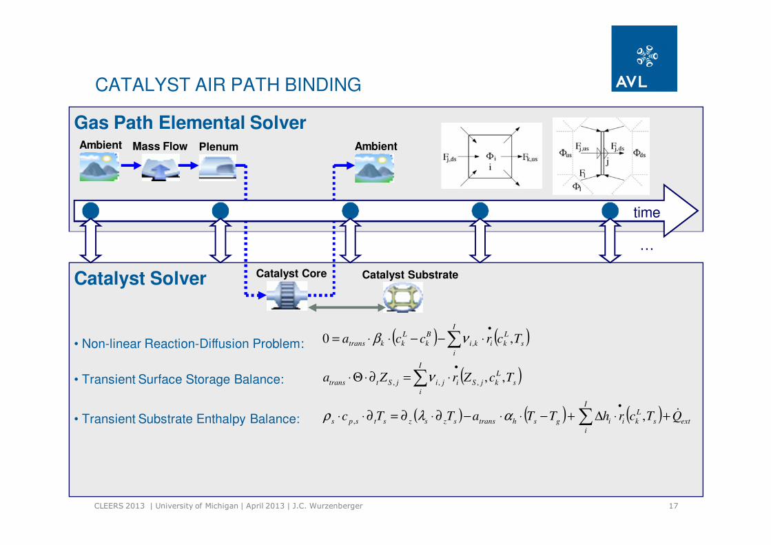
Catalyst Solver
• Non-linear Reaction-Diffusion Problem:
• Transient Substrate Enthalpy Balance:
( ) ( )
( )
( ) ( ) ( )ext
I
i
s
L
kiigshtransszszstsps
I
i
s
L
kjSijijSttrans
I
i
s
L
kiki
B
k
L
kktrans
QTcrhTTaTTc
TcZrZa
Tcrcca
&+⋅∆+−⋅⋅−∂⋅∂=∂⋅⋅
⋅=∂⋅Θ⋅
⋅−−⋅⋅=
∑
∑
∑
•
•
•
,
,,
,0
,
,,,
,
αλρ
ν
νβ
• Transient Surface Storage Balance:
CATALYST AIR PATH BINDING
Gas Path Elemental Solver
Catalyst SubstrateCatalyst Core
Ambient PlenumMass Flow Ambient
time
…
18CLEERS 2013 | University of Michigan | April 2013 | J.C. Wurzenberger
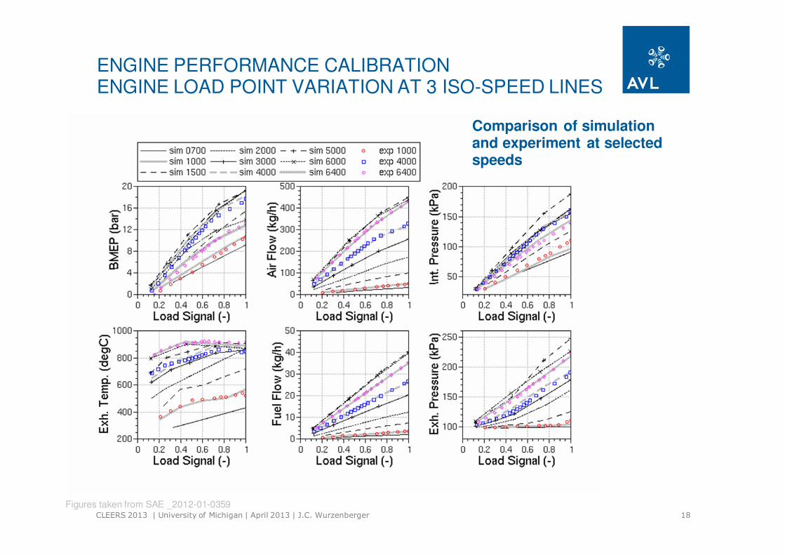
ENGINE PERFORMANCE CALIBRATIONENGINE LOAD POINT VARIATION AT 3 ISO-SPEED LINES
Comparison of simulation and experiment at selected speeds
Figures taken from SAE _2012-01-0359
19CLEERS 2013 | University of Michigan | April 2013 | J.C. Wurzenberger
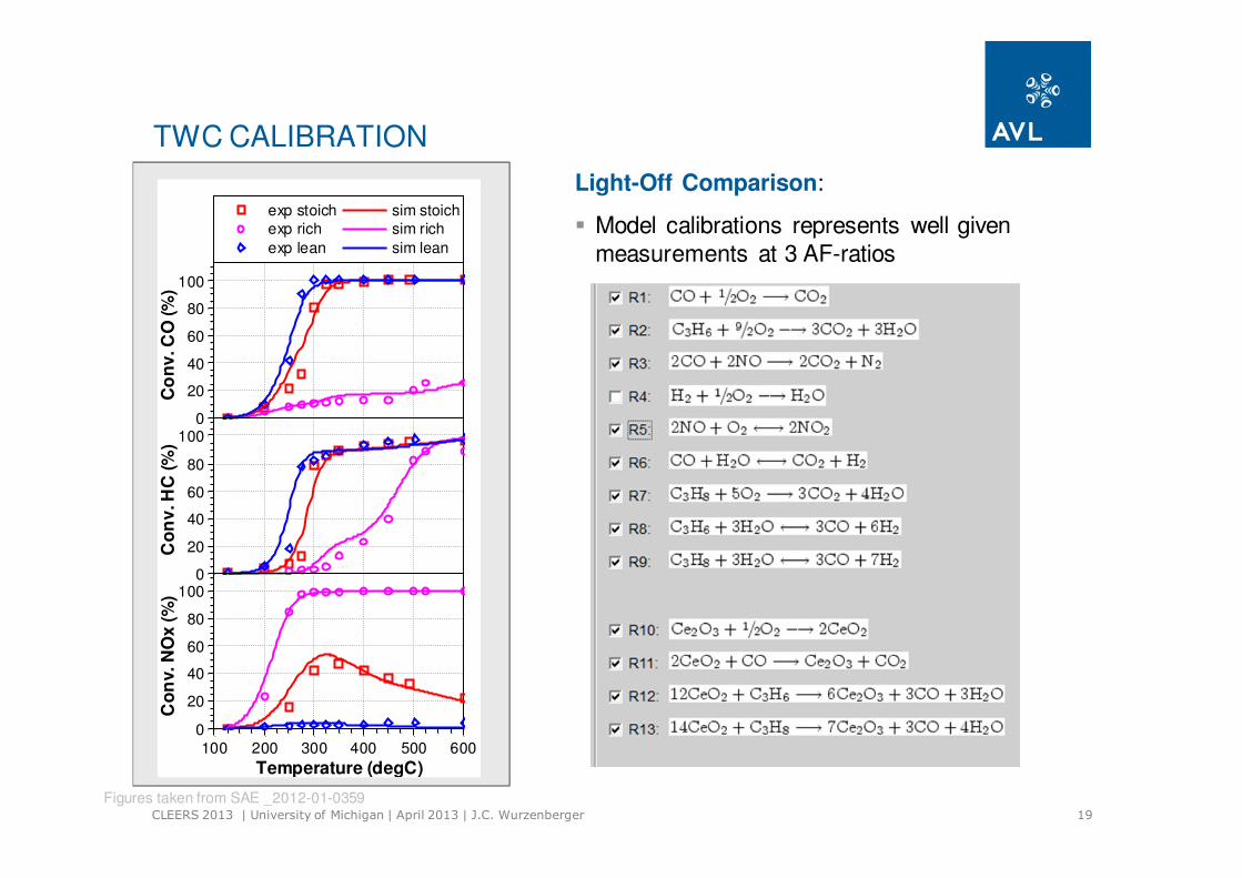
TWC CALIBRATION
Light-Off Comparison:
� Model calibrations represents well given
measurements at 3 AF-ratios
0
20
40
60
80
100
Co
nv
. C
O (
%)
exp stoich
exp rich
exp lean
sim stoich
sim rich
sim lean
0
20
40
60
80
100
Co
nv
. H
C (
%)
0
20
40
60
80
100
Co
nv. N
Ox
(%
)
100 200 300 400 500 600
Temperature (degC)
Figures taken from SAE _2012-01-0359
20CLEERS 2013 | University of Michigan | April 2013 | J.C. Wurzenberger
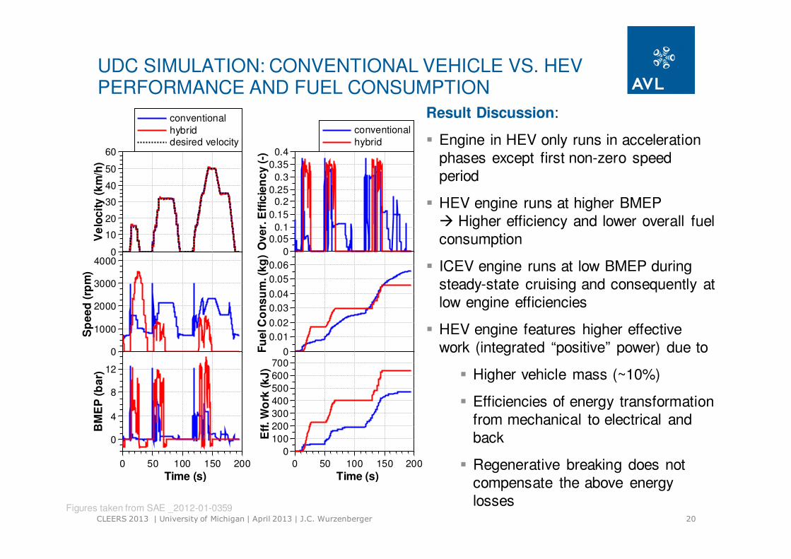
UDC SIMULATION: CONVENTIONAL VEHICLE VS. HEVPERFORMANCE AND FUEL CONSUMPTION
0
10
20
30
40
50
60
Ve
loc
ity
(k
m/h
)
conventional
hybriddesired velocity
0
1000
2000
3000
4000
Sp
ee
d (
rpm
)
0
4
8
12
BM
EP
(b
ar)
0 50 100 150 200
Time (s)
Result Discussion:
� Engine in HEV only runs in acceleration
phases except first non-zero speed
period
� HEV engine runs at higher BMEP
� Higher efficiency and lower overall fuel
consumption
� ICEV engine runs at low BMEP during
steady-state cruising and consequently at
low engine efficiencies
� HEV engine features higher effective
work (integrated “positive” power) due to
� Higher vehicle mass (~10%)
� Efficiencies of energy transformation
from mechanical to electrical and
back
� Regenerative breaking does not
compensate the above energy
losses
0
0.050.1
0.15
0.20.25
0.3
0.35
0.4
Ov
er.
Eff
icie
nc
y (
-)
conventional
hybrid
0
0.01
0.02
0.03
0.04
0.05
0.06F
ue
l C
on
su
m. (k
g)
0
100
200
300
400
500
600
700
Eff
. W
ork
(k
J)
0 50 100 150 200
Time (s)
Figures taken from SAE _2012-01-0359
21CLEERS 2013 | University of Michigan | April 2013 | J.C. Wurzenberger
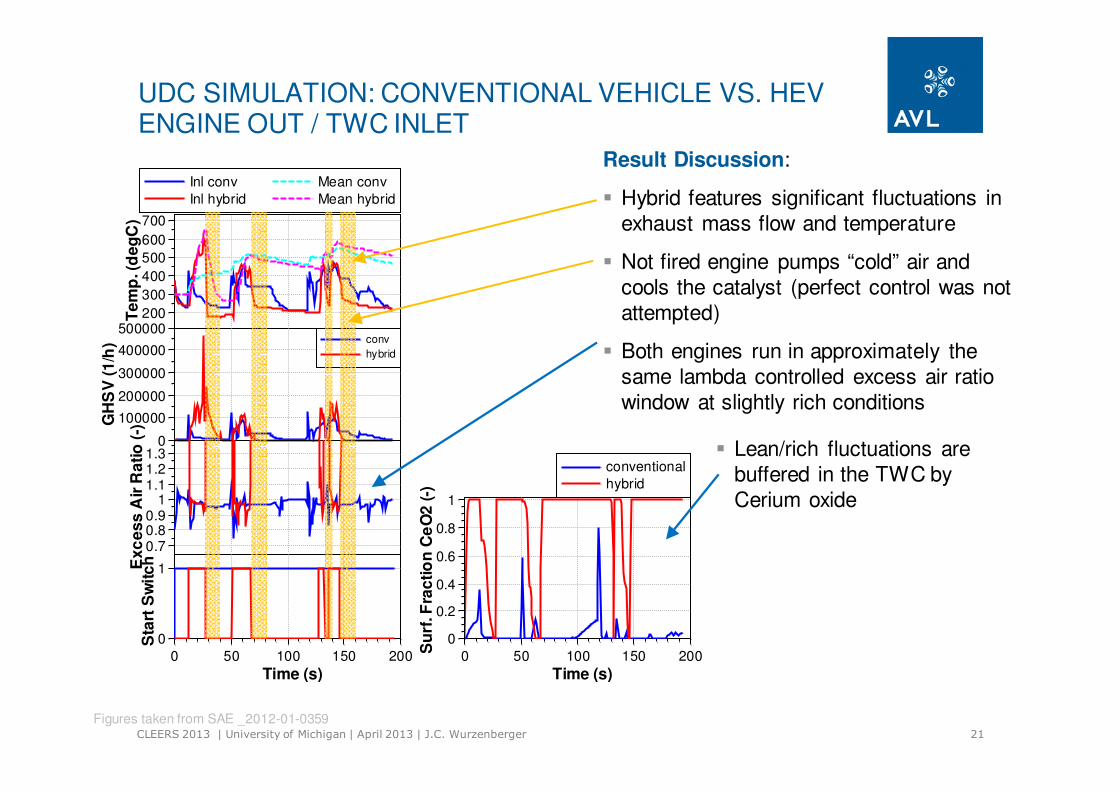
UDC SIMULATION: CONVENTIONAL VEHICLE VS. HEVENGINE OUT / TWC INLET
0
0.2
0.4
0.6
0.8
1
Su
rf. F
rac
tio
n C
eO
2 (
-)
0 50 100 150 200
Time (s)
conventional
hybrid
Result Discussion:
� Hybrid features significant fluctuations in
exhaust mass flow and temperature
� Not fired engine pumps “cold” air and
cools the catalyst (perfect control was not
attempted)
� Both engines run in approximately the
same lambda controlled excess air ratio
window at slightly rich conditions
200
300
400
500
600
700
Te
mp
. (d
eg
C)
Inl conv
Inl hybrid
Mean conv
Mean hybrid
0
100000
200000
300000
400000
500000
GH
SV
(1
/h) conv
hybrid
0.70.80.9
11.11.21.3
Ex
ce
ss
Air
Ra
tio
(-)
0
1
Sta
rt S
wit
ch
0 50 100 150 200
Time (s)
� Lean/rich fluctuations are
buffered in the TWC by
Cerium oxide
Figures taken from SAE _2012-01-0359

22CLEERS 2013 | University of Michigan | April 2013 | J.C. Wurzenberger
UDC SIMULATION: CONVENTIONAL VEHICLE VS. HEVACCUMULATED ENGINE / TAILPIPE EMISSIONS
0
24
6
810
12
Ma
ss
CO
(g
)
Inl conv
Out conv
Inl hybrid
Out hybrid
0
1
2
3
Ma
ss
HC
(g
)
0
0.5
1
1.5
Ma
ss
NO
x (
g)
0 50 100 150 200
Time (s)
Result Discussion:
� Hybrid produces significant emission
steps (due to higher load points and
emission mass flows)
� Conventional vehicle features “continuous
engine out emissions
� Hybrid shows shorter light-off time due to
higher mass flows at the between 12s
and 50s
� Conventional vehicle shows CO and HC
tail pipe emissions between 150s and
200s caused by missing oxygen
� Overall conversion performance of both
vehicle configurations shows no
significant differences
Figures taken from SAE _2012-01-0359
23CLEERS 2013 | University of Michigan | April 2013 | J.C. Wurzenberger
OVERVIEW
� System Engineering Simulation
� Requirements
� Functionalities
� Simulation Examples
� TGDI Engine in Hybrid Passenger Car
� HSDI Diesel Engine in Conventional Passenger Car
� Summary/Conclusions

24CLEERS 2013 | University of Michigan | April 2013 | J.C. Wurzenberger
ENGINE AND VEHICLE MODEL
Engine
� 4-Cylinder HSDI Diesel
� Intercooler
� Cooled EGR
� VTG turbocharger
� DOC DPF SCR
Controller
� Boost pressure (VTG)
� EGR
� Fuelling and smoke
limitation
� idle speed
� Urea dosing
Vehicle
� Front Wheel Passenger Car
� Manual 6 Speed Gear Box
� ASC
� Driver
System engineering model assembled out library elements

25CLEERS 2013 | University of Michigan | April 2013 | J.C. Wurzenberger
CATALYST MODEL CALIBRATION
Catalyst Model Calibration:
� Comparison with experimental
data
� Rates approaches are
reasonable
� Comparison with reference model
� Allows modeling workflow of
rate approaches
� DOC:
� CO, HC. Voltz approach
� NO: reversible power-law
� SCR:
� NH3 ad/desorption
� Standard/Fast/Slow SCR
reaction
� NH3 oxidation
DOC SCR
Figures taken from EAEC 2011_A32 | Valencia
26CLEERS 2013 | University of Michigan | April 2013 | J.C. Wurzenberger
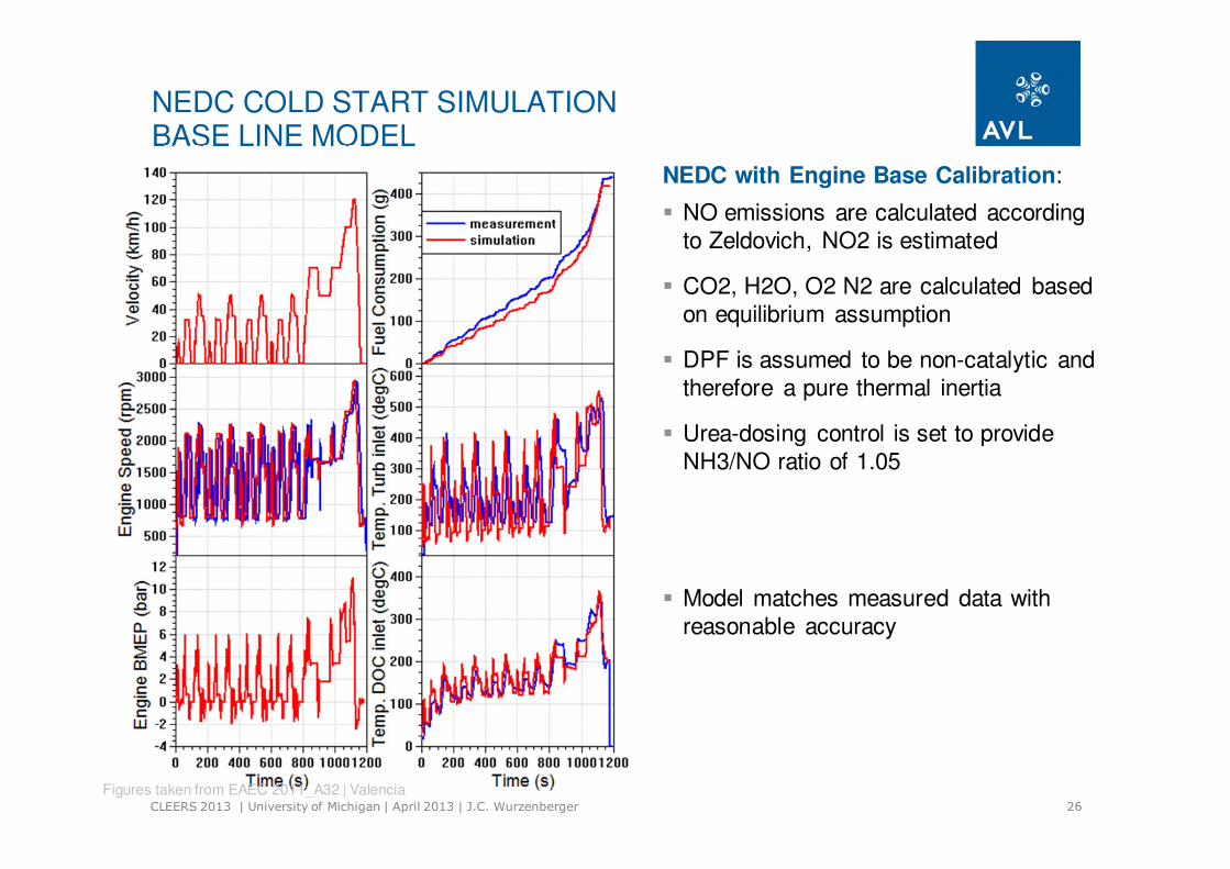
NEDC COLD START SIMULATIONBASE LINE MODEL
NEDC with Engine Base Calibration:
� NO emissions are calculated according
to Zeldovich, NO2 is estimated
� CO2, H2O, O2 N2 are calculated based
on equilibrium assumption
� DPF is assumed to be non-catalytic and
therefore a pure thermal inertia
� Urea-dosing control is set to provide
NH3/NO ratio of 1.05
� Model matches measured data with
reasonable accuracy
Figures taken from EAEC 2011_A32 | Valencia

27CLEERS 2013 | University of Michigan | April 2013 | J.C. Wurzenberger
NEDC COLD START SIMULATIONENGINE CONTROL VARIATIONS
NEDC with Modified Engine Calibration:
� EGR variation shows increasing NO
emissions with decreased EGR due to
higher combustion temperatures and
higher O2 concentrations
� Lower EGR (0.9 ) shows stronger tailpipe
emission deviation from base case than
higher EGR (1.1)
� SOC variation show increasing NO
emissions with earlier SOC due to higher
combustion temperatures
� Earlier SOC (-10degCRA) shows more
pronounced deviation in NO emissions
that late SOC (+10degCRA)
� Earlier SOC and therefore lower engine
out temperatures do additionally
deteriorate the DeNOx performance in
the exhaust lineFigures taken from EAEC 2011_A32 | Valencia

28CLEERS 2013 | University of Michigan | April 2013 | J.C. Wurzenberger
OVERVIEW
� System Engineering Simulation
� Requirements
� Functionalities
� Simulation Examples
� TGDI Engine in Hybrid Passenger Car
� HSDI Diesel Engine in Conventional Passenger Car
� Summary/Conclusions
29CLEERS 2013 | University of Michigan | April 2013 | J.C. Wurzenberger
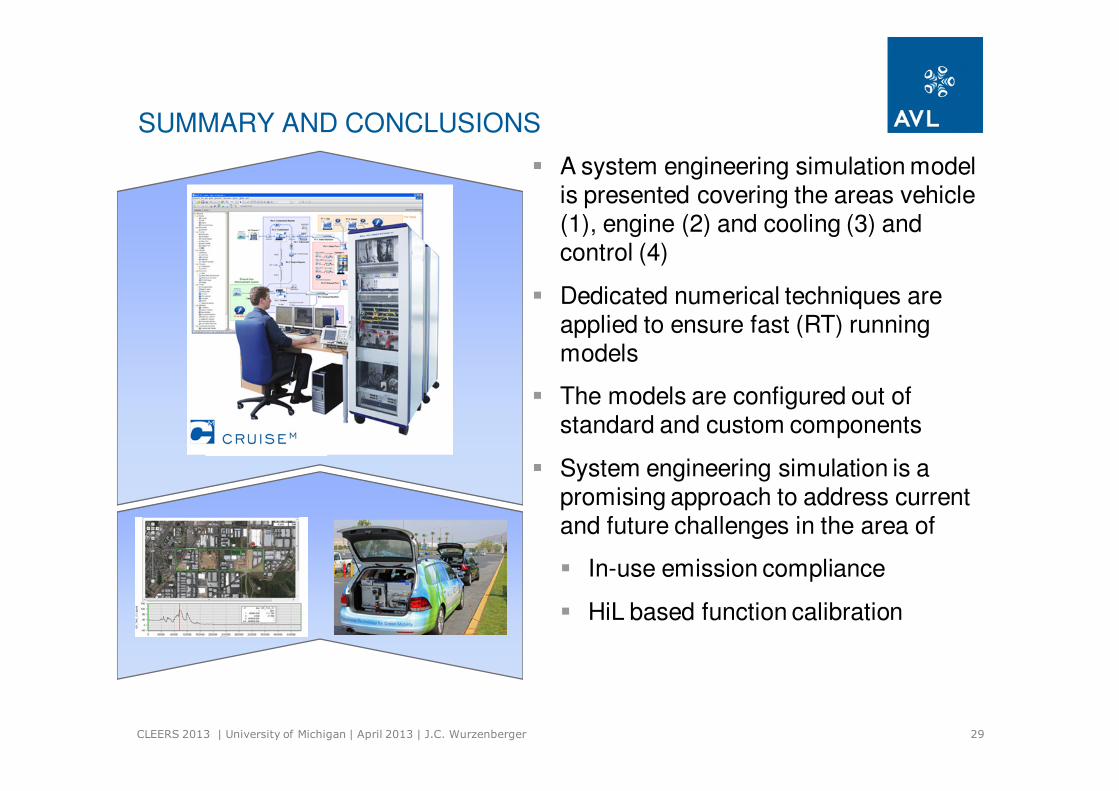
� A system engineering simulation model is presented covering the areas vehicle (1), engine (2) and cooling (3) and control (4)
� Dedicated numerical techniques are applied to ensure fast (RT) runningmodels
� The models are configured out of standard and custom components
� System engineering simulation is a promising approach to address current and future challenges in the area of
� In-use emission compliance
� HiL based function calibration
SUMMARY AND CONCLUSIONS