Exergy Analysis of Flat Plate Solar Collectors · Exergy Analysis of Flat Plate Solar Collectors...
19
Entropy 2014, 16, 2549-2567; doi:10.3390/e16052549 entropy ISSN 1099-4300 www.mdpi.com/journal/entropy Article Exergy Analysis of Flat Plate Solar Collectors Zhong Ge 1 , Huitao Wang 1, *, Hua Wang 1 , Songyuan Zhang 1 and Xin Guan 2 1 Engineering Research Center of Metallurgical Energy Conservation and Emission Reduction, Ministry of Education Kunming University of Science and Technology, Kunming 650093, China; E-Mails: [email protected](Z.G.); [email protected](H.W.); [email protected](S.Y.Z.) 2 School of Energy and power Engineering, University of Shanghai For Science and Technology, Shanghai 200093, China; E-Mail: [email protected] * Author to whom correspondence should be addressed; E-Mail: [email protected]; Tel.: +86-0871-65153405. Received: 19 November 2013; in revised form: 1 April 2014 / Accepted: 5 May 2014 / Published: 9 May 2014 Abstract: This study proposes the concept of the local heat loss coefficient and examines the calculation method for the average heat loss coefficient and the average absorber plate temperature. It also presents an exergy analysis model of flat plate collectors, considering non-uniformity in temperature distribution along the absorber plate. The computation results agree well with experimental data. The effects of ambient temperature, solar irradiance, fluid inlet temperature, and fluid mass flow rate on useful heat rate, useful exergy rate, and exergy loss rate are examined. An optimal fluid inlet temperature exists for obtaining the maximum useful exergy rate. The calculated optimal fluid inlet temperature is 69 °C, and the maximum useful exergy rate is 101.6 W. Exergy rate distribution is analyzed when ambient temperature, solar irradiance, fluid mass flow rate, and fluid inlet temperature are set to 20 °C, 800 W/m 2 , 0.05 kg/s, and 50 °C, respectively. The exergy efficiency is 5.96%, and the largest exergy loss is caused by the temperature difference between the absorber plate surface and the sun, accounting for 72.86% of the total exergy rate. Keywords: flat plate collector; heat loss coefficient; exergy; exergy loss OPEN ACCESS
Transcript of Exergy Analysis of Flat Plate Solar Collectors · Exergy Analysis of Flat Plate Solar Collectors...
Entropy 2014, 16, 2549-2567; doi:10.3390/e16052549
entropy ISSN 1099-4300
www.mdpi.com/journal/entropy
Article
Exergy Analysis of Flat Plate Solar Collectors
Zhong Ge 1, Huitao Wang 1,*, Hua Wang 1, Songyuan Zhang 1 and Xin Guan 2
1 Engineering Research Center of Metallurgical Energy Conservation and Emission Reduction, Ministry
of Education Kunming University of Science and Technology, Kunming 650093, China;
E-Mails: [email protected](Z.G.); [email protected](H.W.); [email protected](S.Y.Z.) 2 School of Energy and power Engineering, University of Shanghai For Science and Technology,
Shanghai 200093, China; E-Mail: [email protected]
* Author to whom correspondence should be addressed; E-Mail: [email protected];
Tel.: +86-0871-65153405.
Received: 19 November 2013; in revised form: 1 April 2014 / Accepted: 5 May 2014 /
Published: 9 May 2014
Abstract: This study proposes the concept of the local heat loss coefficient and examines
the calculation method for the average heat loss coefficient and the average absorber plate
temperature. It also presents an exergy analysis model of flat plate collectors, considering
non-uniformity in temperature distribution along the absorber plate. The computation
results agree well with experimental data. The effects of ambient temperature, solar
irradiance, fluid inlet temperature, and fluid mass flow rate on useful heat rate, useful
exergy rate, and exergy loss rate are examined. An optimal fluid inlet temperature exists
for obtaining the maximum useful exergy rate. The calculated optimal fluid inlet
temperature is 69 °C, and the maximum useful exergy rate is 101.6 W. Exergy rate
distribution is analyzed when ambient temperature, solar irradiance, fluid mass flow rate,
and fluid inlet temperature are set to 20 °C, 800 W/m2, 0.05 kg/s, and 50 °C, respectively.
The exergy efficiency is 5.96%, and the largest exergy loss is caused by the temperature
difference between the absorber plate surface and the sun, accounting for 72.86% of the
total exergy rate.
Keywords: flat plate collector; heat loss coefficient; exergy; exergy loss
OPEN ACCESS
Entropy 2014, 16 2550
1. Introduction
Solar energy, a clean and renewable energy source with no harmful environmental effects, has
received considerable attention for generating heat and electricity [1,2]. The flat plate solar collector is
the main component of solar heating systems. Thus, the performance of the plate solar collector is
important. To analyze the performance of solar collectors, the energy equation alone does not account
for internal losses, so it is not a sufficient criterion for flat plate solar collector efficiency [3].
Therefore, an analysis based on the second law of thermodynamics that determines the exergy of the
system is necessary. The effect of some vital parameters on the exergy of flat plate collectors is also
necessary to optimize solar system design and operation.
Solar collectors have been examined in terms of their exergy, exergy efficiency, and entropy
generation [4–6]. Bejan et al. conducted an exergy analysis of a solar collector and found that the
amount of exergy delivered by solar collector systems is affected by heat transfer irreversibilities [7].
Suzuki compared flat plate and evacuated tube collectors in terms of exergy [8]. Jafarkazemi et al.
conducted both energy and exergy analyses of a flat plate solar collector [9]. Luminosu and Fara
proposed an exergy analysis of a flat plate solar collector based on the assumption that fluid inlet
temperature is equal to ambient temperature [10]. Farahat et al. attempted to determine the optimum
values of the mass flow rate, absorber plate area, and maximum exergy efficiency of a flat plate
collector [11]. Akpinar et al. experimentally compared a flat plate solar air heater with several
obstacles and one without and found that the efficiency of solar air collectors significantly depends on
the solar radiation, the surface geometry of the collectors, and the extension of the air flow line [12].
Alta et al. experimentally compared three plate solar air heaters based on energy and exergy output and
found that the heater with double glass covers and fins is more effective than the other two heaters [13].
In all of these studies, however, collector performance was evaluated without considering non-uniformity in
the temperature distribution of the absorber plate or even assuming a constant overall heat loss coefficient.
The present work presents a theoretical model considering non-uniformity in temperature
distribution along the absorber plate for the exergy analysis of flat plate solar collectors. The model has
also been experimentally verified.
2. Theoretical Model
2.1. Energy Equation for Flat Plate Solar Collectors
A micro unit dA is taken from the absorber plate in steady state according to the first law of
thermodynamics [14]:
u s l l p aQ Q Q S U T T dA (1)
where Qu is the useful heat rate gain of the flat plate solar collector, Qs is the radiation flux absorbed by
the absorber plate, Ql is the heat loss from the solar collector to the environment, S is the radiation flux
absorbed by a unit area of the absorber plate, Ul is the local heat loss coefficient of dA, Tp is the
temperature of dA, and Ta is the ambient temperature.
Entropy 2014, 16 2551
According to the integral mean value theorem, the following can be deduced from Equation (1):
p
l p a p l p a
A
u S U T T dA A S U TQ T (2)
where Ap is the area of the absorber plate, lU is the integral average of Ul over the absorber plate, and
pT is the integral average of Tp over the absorber plate.
2.2. Calculation Methodology for Average Heat Loss Coefficient and Average Absorber Plate Temperature
To simplify the model, the following assumptions are made:
(1) The plate is in a steady-state heat transfer condition.
(2) The temperature gradient in the direction of the fin thickness is negligible.
(3) The fluid mass flow rate inside metal tubes is uniform.
(4) The pressure drop of the fluid inside metal tubes is neglected.
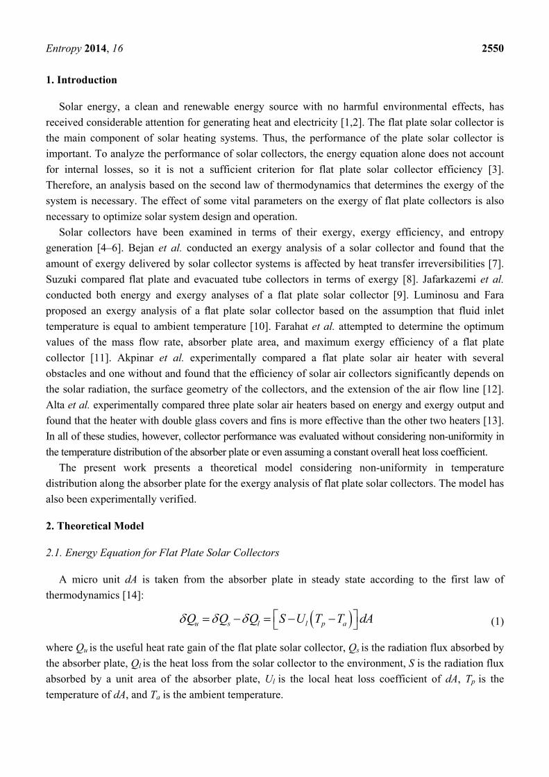
The absorber plate is composed of metal tubes and fins, it is shown in Figure 1:
Figure 1. Absorber plate consisting of metal tubes and fins.
Establishing coordinate system as Figure 1, a micro unit dy is taken from the absorber plate. The
heat transferred from the absorber plate to the glass comprises radiative heat and convective heat. The
radiative heat transfer from the absorber plate to the glass of dy is:
4 41
, 11
1
1 11
p
r pp
p
T Tq dy
W W W
(3)
where W is the width of the metal tube and fins (tube center to center distance), σ is the Stefan–
Boltzmann constant, pT is the average temperature of dy, T1 is the temperature of the glass, εp is the
emissivity of the absorber plate, and ε1 is the emissivity of the glass.
The convective heat transfer coefficient between the absorber plate and the glass is calculated from
the Nusselt number according to the following Equation [15]:
Entropy 2014, 16 2552
1.6
1/3 1/3
sin1.8 17081708 17081 1.44 1 (1 ) / 2 1
cos cos cos
cos cos1 1 / 2
5830 5830
NuRa Ra Ra
Ra Ra
(4)
31( )pg d T T
Rav
(5)
, 1air
c p
Nukh
d
(6)
where θ is the collector tilt relative to the horizontal, Ra is the Rayleigh number, g is the gravity, β is
the thermal expansion coefficient, d is the distance between the absorber plate and glass, α is the
thermal diffusivity, v is the kinematic viscosity, and kair is the thermal conductivity of air.
The convective heat transferred from the absorber plate to the glass of dy is:
, 1 1 , 1c p p c pq W T T h dy (7)
The radiative heat transferred from the glass to the sky of dy is as follows [16]:
4 4,1 1 1r a skyq W T T dy
(8)
where the temperature of the sky is 1.50.0552sky aT T .
The convective heat transfer coefficient between the glass and the environment is as follows [17]:
5.7 3.8w ah V (9)
where Va is the wind speed.
The convective heat transferred from the glass to the environment of dy is:
,1 1c a w aq Wh T T dy (10)
The following equation must hold in steady state:
, 1 , 1 ,1 ,1r p c p r a c aq q q q (11)
The top local heat loss coefficient of dy ,l tU is:
, 1 , 1,
( )r p c p
l t
p a
q qU
W T T dy
(12)
The heat loss coefficient consists of the top, back, and edge heat loss coefficients.
The back heat loss coefficient is calculated as follows [18]:
lb
b
kU
L
(13)
where kl is the thermal conductivity of the insulation material and Lb is the thickness of the insulation
material in back.
The edge heat loss coefficient is estimated as follows [18]:
Entropy 2014, 16 2553
l ee
e p
k AU
L A
(14)
where Ae is the side area of the collector and Le is the thickness of the insulation material at the side.
The local heat loss coefficient of dy is as follows [18]:
,l l t b eU U U U (15)
According to Equations (3) to (15), if pT is known, lU can be calculated by a numerical method.
Given that the fin thickness is smaller than the width, the temperature gradient in the direction of the
fin thickness is neglected. The temperature distribution of the fin in the x direction is as follows [18]:
cosh
cosh2
n a
l
ob a
l
ST T
U BxS B W DT T
U
(16)
where nT is the fin temperature, /lB U , λ is the thermal conductivity of the fins, δ is the fin
thickness, Tb is the metal tube temperature, and Do is the metal tube outer diameter.
In the steady state, the heat obtained by the absorber plate is equal to the heat obtained by the metal
tube and fins. The heat obtained by dy is as follows [14,18]:
u l f aq WF S U T T dy
(17)
,
1
l
i f i o o n
WU WD h
F
D W D
(18)
where F is the collector efficiency factor, Tf is the fluid temperature, Di is the metal tube inner
diameter, and hf,i is the convective heat transfer coefficient between the metal tube and fluid.
Fin efficiency can be determined as follows [18]:
tanh / 2 / / 2n o oB W D B W D (19)
The heat obtained by the absorber plate is finally transferred to the fluid, thermal contact resistance is neglected, and uq can be expressed as follows [18]:
,
1b f
u
i f i
T Tq dy
D h
(20)
The relationship between the metal tube and fluid temperatures can then be deduced by Equations
(17)–(20):
,
l f a
b fi f i
WF S U T TT T
D h
(21)
Entropy 2014, 16 2554
According to Equation (21), if Tf is defined by an assumed initial value and lU is calculated by
assumed pT , then Tb can be computed. Substituting Tb into Equation (16) yields the relationship
between Tn and x:
cosh
cosh2
n b a ao l l
Bx S ST T T T
B W D U U
(22)
The average fin temperature of dy I s:
2
0
2
oW D
n
no
T dxT
W D
(23)
The average temperature of dy is:
o b o np
D T W D TT
W
(24)
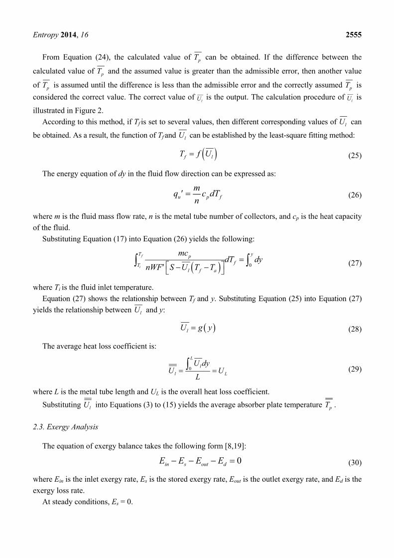
Figure 2. Flow chart of simulation program for evaluating lU .
Entropy 2014, 16 2555
From Equation (24), the calculated value of pT can be obtained. If the difference between the
calculated value of pT and the assumed value is greater than the admissible error, then another value
of pT is assumed until the difference is less than the admissible error and the correctly assumed pT is
considered the correct value. The correct value of lU is the output. The calculation procedure of
lU is
illustrated in Figure 2.
According to this method, if Tf is set to several values, then different corresponding values of lU can
be obtained. As a result, the function of Tf and lU can be established by the least-square fitting method:
f lT f U
(25)
The energy equation of dy in the fluid flow direction can be expressed as:
u p f
mq c dT
n
(26)
where m is the fluid mass flow rate, n is the metal tube number of collectors, and cp is the heat capacity
of the fluid.
Substituting Equation (17) into Equation (26) yields the following:
0
f
i
y
f
l f a
T p
T
mc
nWFdT dy
S U T T
(27)
where Ti is the fluid inlet temperature.
Equation (27) shows the relationship between Tf and y. Substituting Equation (25) into Equation (27)
yields the relationship between lU and y:
lU g y (28)
The average heat loss coefficient is:
0
L
l
l L
U dyU U
L
(29)
where L is the metal tube length and UL is the overall heat loss coefficient.
Substituting lU into Equations (3) to (15) yields the average absorber plate temperature pT .
2.3. Exergy Analysis
The equation of exergy balance takes the following form [8,19]:
0in s out dE E E E (30)
where Ein is the inlet exergy rate, Es is the stored exergy rate, Eout is the outlet exergy rate, and Ed is the
exergy loss rate.
At steady conditions, Es = 0.
Entropy 2014, 16 2556
The inlet exergy rate consists of the inlet exergy carried by fluid flow and the radiation exergy rate
from the sun. The rate of inlet exergy carried by fluid flow is as follows [20,21]:
, ( ln( ))iin f p i a a
a
TE mc T T T
T (31)
The radiation exergy rate from the sun on the collector surface can be calculated as follows [6]:
, (1 )acin Q
s
ET
IAT
(32)
where I is the solar irradiance and Ac is the aperture area. The apparent solar temperature as exergy
source Ts is assumed to be 4350 K [11].
The rate of outlet exergy carried by fluid flow is as follows [20,21]:
, ( ln( ))oout f p o a a
a
TE mc T T T
T (33)
where To is the fluid outlet temperature.
The exergy loss rate consists of the following four parts:
The first part of the exergy loss rate is caused by heat leakage from the absorber plate to the
environment [3]:
( )(1 )p
p
al L p a
TE U A TT
T (34)
The second part of the exergy loss rate is caused by the temperature difference between the absorber
plate surface and the Sun [3]:
1
1 1( ) ( )d e p a
spT
E IA TT
(35)
where (τα)e is the effective product transmittance–absorptance.
The third part of the exergy loss rate is due to solar radiation losses from the collector surface to the
absorber plate:
2 ( ) (1 )ac e p
sd
TI A AE
T (36)
The fourth part of the exergy loss rate is caused by the temperature difference between the absorber
plate and fluid [21]:
3
( )ln( )o o
ai
p
di
p
T T Tc T
T TE m
(37)
According to Equations (30) to (37), the useful exergy rate is:
, ,u out f in fE E E (38)
Entropy 2014, 16 2557
Solar collector exergy efficiency is calculated by dividing the increase in fluid flow exergy by the
inlet radiation exergy [9]:
, ,
(1 )
out f in fex
ac
s
E E
TIA
T
(39)
According to Equations (30)–(37), the fluid outlet temperature To can be obtained. Substituting relevant
data into Equations (34)–(39) yields the useful exergy rate, exergy loss rate, and exergy efficiency.
3. Validation of Methodology
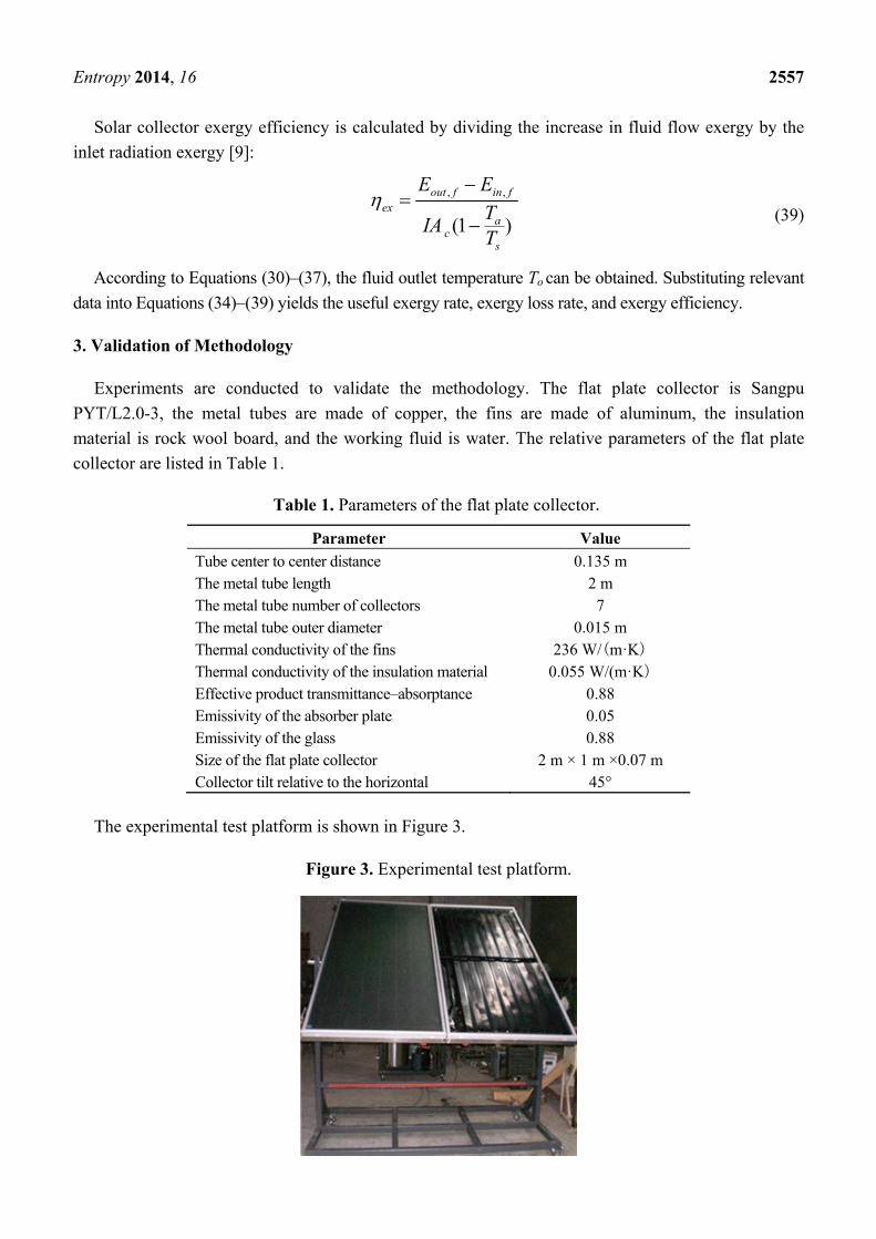
Experiments are conducted to validate the methodology. The flat plate collector is Sangpu
PYT/L2.0-3, the metal tubes are made of copper, the fins are made of aluminum, the insulation
material is rock wool board, and the working fluid is water. The relative parameters of the flat plate
collector are listed in Table 1.
Table 1. Parameters of the flat plate collector.
Parameter Value
Tube center to center distance 0.135 m The metal tube length 2 m The metal tube number of collectors 7 The metal tube outer diameter 0.015 m Thermal conductivity of the fins 236 W/(m·K) Thermal conductivity of the insulation material 0.055 W/(m·K) Effective product transmittance–absorptance 0.88 Emissivity of the absorber plate 0.05 Emissivity of the glass 0.88 Size of the flat plate collector 2 m × 1 m ×0.07 m Collector tilt relative to the horizontal 45°
The experimental test platform is shown in Figure 3.
Figure 3. Experimental test platform.
Entropy 2014, 16 2558
The values calculated by the above method and experimental data are compared, and the results are
shown in Table 2.
Table 2. Comparison between calculated values and experimental data.
Time
10–11 11–12 12–13 13–14 14–15 15–16
I/(W/m2) 631 702 713 640 535 374 Ta/°C 25.5 26.4 27.7 27.5 26.8 25.7 Ti/°C 29.4 37.3 44.6 51.9 61.1 67.2 ηex.calc/% 1.56 3.09 4.10 4.85 4.86 2.44 ηex.exp/% 1.62 2.96 3.95 4.79 4.90 2.59 Eexergy/% 3.70 4.39 3.80 1.25 0.82 5.79
An experiment is conducted in six time segments of a day. The fluid inlet temperature is controlled
by an electrically heated constant-temperature water bath. The fluid inlet temperature of each
measurement is different, and the mass flow rate is controlled at 0.05 kg/s by adjusting the valve.
When the collector is in steady state (i.e., ambient temperature: ± 1 °C; solar irradiance: ± 50 W/m2;
fluid inlet temperature: ± 0.1 °C; fluid mass flow rate: ± 1%), the experimental data are collected. Four
independent data acquisition procedures are conducted for each individual test point, and the collection
intervals are at least 3 minutes long. ηex.calc is the calculated exergy efficiency, ηex.exp is the experimental
efficiency, and Eexergy is the relative error. Table 2 shows that only a small difference was observed
between the calculated values and experimental results.
4. Results and Discussion
With the suggested calculation method of this study, the effects of ambient temperature, solar
irradiance, fluid mass flow rate, and fluid inlet temperature on the useful heat rate, useful exergy rate,
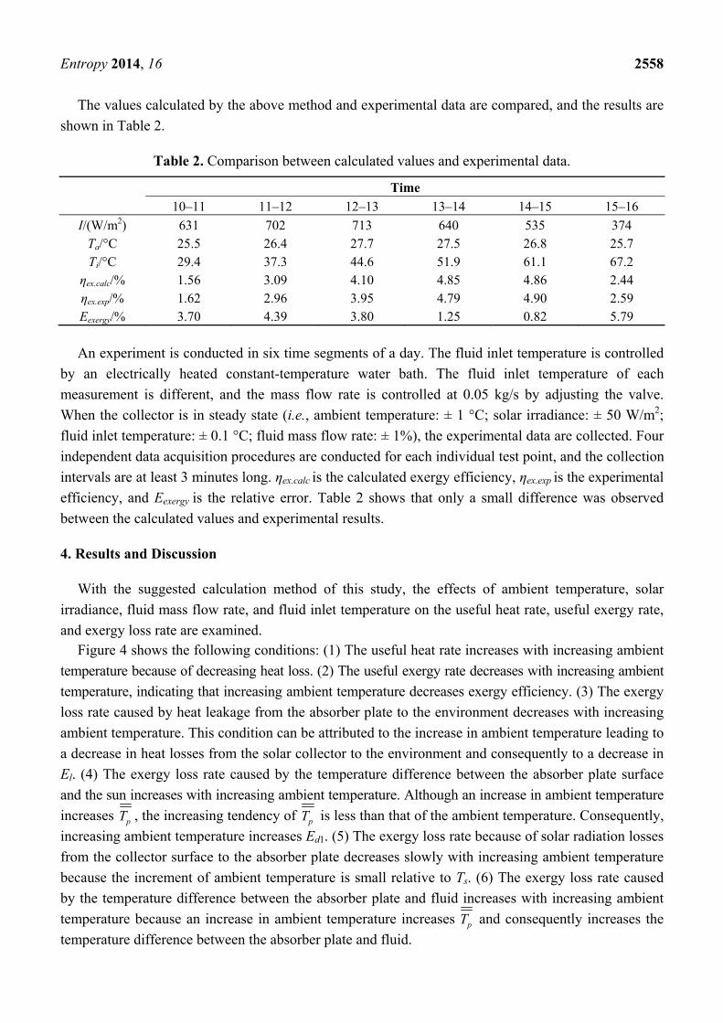
and exergy loss rate are examined. Figure 4 shows the following conditions: (1) The useful heat rate increases with increasing ambient
temperature because of decreasing heat loss. (2) The useful exergy rate decreases with increasing ambient
temperature, indicating that increasing ambient temperature decreases exergy efficiency. (3) The exergy
loss rate caused by heat leakage from the absorber plate to the environment decreases with increasing
ambient temperature. This condition can be attributed to the increase in ambient temperature leading to
a decrease in heat losses from the solar collector to the environment and consequently to a decrease in
El. (4) The exergy loss rate caused by the temperature difference between the absorber plate surface
and the sun increases with increasing ambient temperature. Although an increase in ambient temperature
increases pT , the increasing tendency of pT is less than that of the ambient temperature. Consequently,
increasing ambient temperature increases Ed1. (5) The exergy loss rate because of solar radiation losses
from the collector surface to the absorber plate decreases slowly with increasing ambient temperature
because the increment of ambient temperature is small relative to Ts. (6) The exergy loss rate caused
by the temperature difference between the absorber plate and fluid increases with increasing ambient
temperature because an increase in ambient temperature increases pT and consequently increases the
temperature difference between the absorber plate and fluid.
Entropy 2014, 16 2559
Figure 4. Variations of useful heat rate, useful exergy rate, and exergy loss rate versus
ambient temperature.
The useful heat rate and useful exergy rate have conflicting behavior with increasing ambient
temperature. Although El decreases from 65.7 W to 31.8 W with ambient temperature increasing from
14 °C to 28 °C (the reduction proportion is more than 50%), Eu decreases from 97.2 W to 74.0 W
because of increasing Ed1 and Ed3 and decreasing Ein,Q.
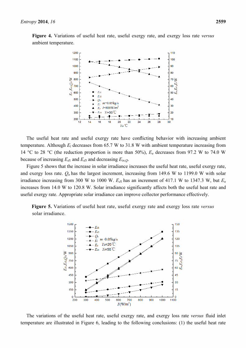
Figure 5 shows that the increase in solar irradiance increases the useful heat rate, useful exergy rate,
and exergy loss rate. Qu has the largest increment, increasing from 149.6 W to 1199.0 W with solar
irradiance increasing from 300 W to 1000 W. Ed1 has an increment of 417.1 W to 1347.3 W, but Eu
increases from 14.0 W to 120.8 W. Solar irradiance significantly affects both the useful heat rate and
useful exergy rate. Appropriate solar irradiance can improve collector performance effectively.
Figure 5. Variations of useful heat rate, useful exergy rate and exergy loss rate versus
solar irradiance.
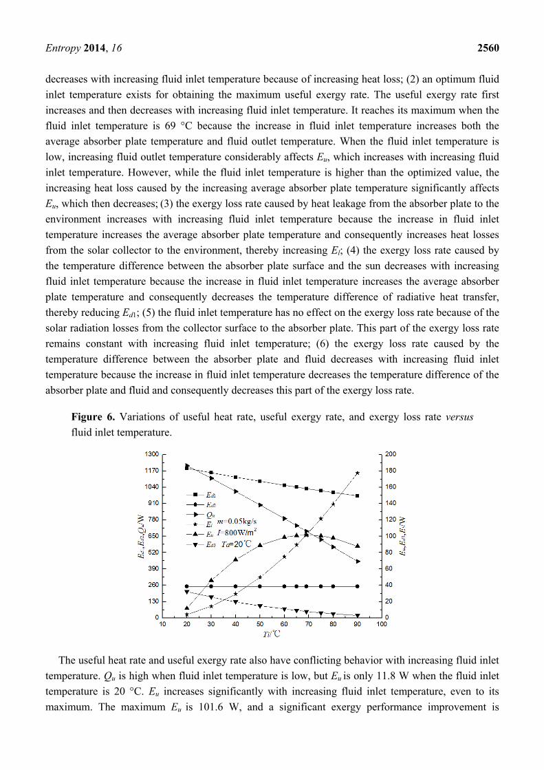
The variations of the useful heat rate, useful exergy rate, and exergy loss rate versus fluid inlet
temperature are illustrated in Figure 6, leading to the following conclusions: (1) the useful heat rate
Entropy 2014, 16 2560
decreases with increasing fluid inlet temperature because of increasing heat loss; (2) an optimum fluid
inlet temperature exists for obtaining the maximum useful exergy rate. The useful exergy rate first
increases and then decreases with increasing fluid inlet temperature. It reaches its maximum when the
fluid inlet temperature is 69 °C because the increase in fluid inlet temperature increases both the
average absorber plate temperature and fluid outlet temperature. When the fluid inlet temperature is
low, increasing fluid outlet temperature considerably affects Eu, which increases with increasing fluid
inlet temperature. However, while the fluid inlet temperature is higher than the optimized value, the
increasing heat loss caused by the increasing average absorber plate temperature significantly affects
Eu, which then decreases; (3) the exergy loss rate caused by heat leakage from the absorber plate to the
environment increases with increasing fluid inlet temperature because the increase in fluid inlet
temperature increases the average absorber plate temperature and consequently increases heat losses
from the solar collector to the environment, thereby increasing El; (4) the exergy loss rate caused by
the temperature difference between the absorber plate surface and the sun decreases with increasing
fluid inlet temperature because the increase in fluid inlet temperature increases the average absorber
plate temperature and consequently decreases the temperature difference of radiative heat transfer,
thereby reducing Ed1; (5) the fluid inlet temperature has no effect on the exergy loss rate because of the
solar radiation losses from the collector surface to the absorber plate. This part of the exergy loss rate
remains constant with increasing fluid inlet temperature; (6) the exergy loss rate caused by the
temperature difference between the absorber plate and fluid decreases with increasing fluid inlet
temperature because the increase in fluid inlet temperature decreases the temperature difference of the
absorber plate and fluid and consequently decreases this part of the exergy loss rate.
Figure 6. Variations of useful heat rate, useful exergy rate, and exergy loss rate versus
fluid inlet temperature.
The useful heat rate and useful exergy rate also have conflicting behavior with increasing fluid inlet
temperature. Qu is high when fluid inlet temperature is low, but Eu is only 11.8 W when the fluid inlet
temperature is 20 °C. Eu increases significantly with increasing fluid inlet temperature, even to its
maximum. The maximum Eu is 101.6 W, and a significant exergy performance improvement is
Entropy 2014, 16 2561
observed. The optimum fluid inlet temperature varies. It is mainly affected by heat loss because of the
flat plate collector’s structure. El increases rapidly from 4.3 W to 177.5 W when fluid inlet temperature
rises from 20 °C to 90 °C. Selecting appropriate evaluation criteria for the collector based on specific
conditions and allowing the collector to work with appropriate fluid inlet temperature are recommended.
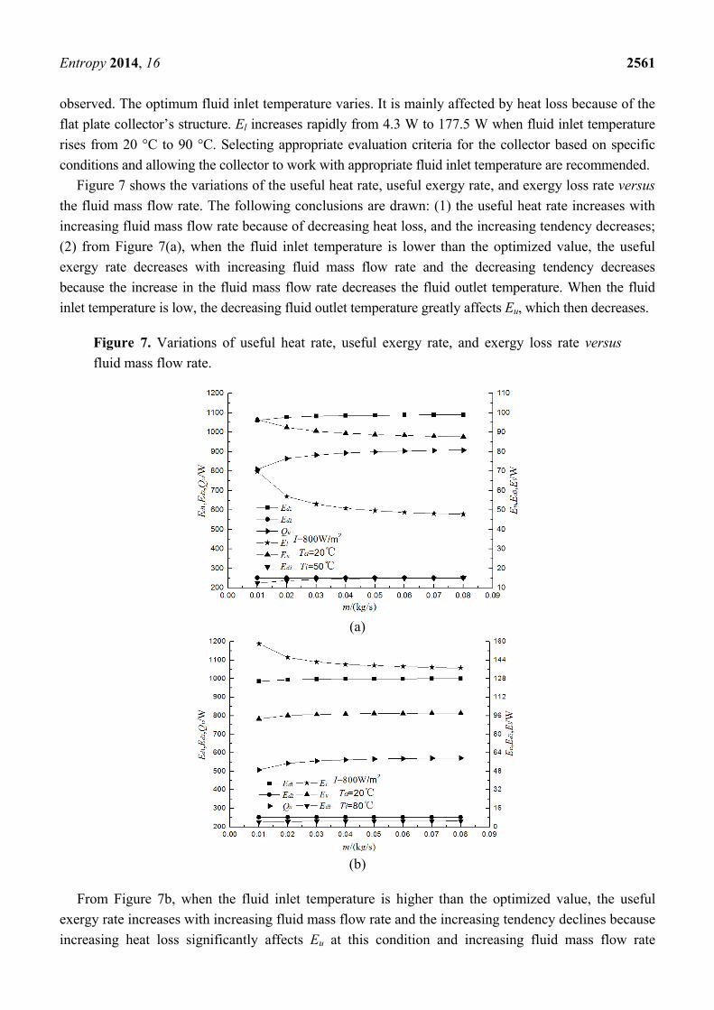
Figure 7 shows the variations of the useful heat rate, useful exergy rate, and exergy loss rate versus
the fluid mass flow rate. The following conclusions are drawn: (1) the useful heat rate increases with
increasing fluid mass flow rate because of decreasing heat loss, and the increasing tendency decreases;
(2) from Figure 7(a), when the fluid inlet temperature is lower than the optimized value, the useful
exergy rate decreases with increasing fluid mass flow rate and the decreasing tendency decreases
because the increase in the fluid mass flow rate decreases the fluid outlet temperature. When the fluid
inlet temperature is low, the decreasing fluid outlet temperature greatly affects Eu, which then decreases.
Figure 7. Variations of useful heat rate, useful exergy rate, and exergy loss rate versus
fluid mass flow rate.
(a)
(b)
From Figure 7b, when the fluid inlet temperature is higher than the optimized value, the useful
exergy rate increases with increasing fluid mass flow rate and the increasing tendency declines because
increasing heat loss significantly affects Eu at this condition and increasing fluid mass flow rate
Entropy 2014, 16 2562
decreases heat losses from the solar collector to the environment; (3) the exergy loss rate caused by
heat leakage from the absorber plate to the environment decreases with increasing fluid mass flow rate
and the decreasing tendency decreases because the increase in fluid mass flow rate decreases the
average absorber plate temperature and consequently decreases heat losses from the solar collector to
the environment; (4) The exergy loss rate caused by the temperature difference between the absorber
plate surface and the sun increases with increasing fluid mass flow rate and the increasing tendency
decreases because the increase in fluid mass flow rate decreases the average absorber plate temperature
and consequently increases the temperature difference of radiative heat transfer. Thus, this part of the
exergy loss rate increases; (5) the fluid mass flow rate has no effect on the exergy loss rate because of
solar radiation losses from the collector surface to the absorber plate. This part of the exergy loss rate
remains constant with increasing fluid mass flow rate; (6) the exergy loss rate caused by the
temperature difference between the absorber plate and the fluid increases with increasing fluid mass
flow rate because the increase in the fluid mass flow rate increases the heat transfer between the
absorber plate and fluid and consequently increases this part of the exergy loss rate.
When the fluid inlet temperature is lower than the optimized value, the variation trends of Qu and Eu
are opposite those of the increasing fluid mass flow rate. When the fluid inlet temperature is higher
than the optimized value, the variation trends of Qu and Eu are the same. Notably, the effect of the
mass flow rate on performance declines with increasing mass flow rate. The mass flow rate should be
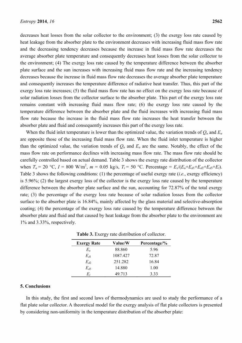
carefully controlled based on actual demand. Table 3 shows the exergy rate distribution of the collector
when Ta = 20 °C, I = 800 W/m2, m = 0.05 kg/s, Ti = 50 °C. Percentage = Ex/(Eu+Ed1+Ed2+Ed3+El).
Table 3 shows the following conditions: (1) the percentage of useful exergy rate (i.e., exergy efficiency)
is 5.96%; (2) the largest exergy loss of the collector is the exergy loss rate caused by the temperature
difference between the absorber plate surface and the sun, accounting for 72.87% of the total exergy
rate; (3) the percentage of the exergy loss rate because of solar radiation losses from the collector
surface to the absorber plate is 16.84%, mainly affected by the glass material and selective-absorption
coating; (4) the percentage of the exergy loss rate caused by the temperature difference between the
absorber plate and fluid and that caused by heat leakage from the absorber plate to the environment are
1% and 3.33%, respectively.
Table 3. Exergy rate distribution of collector.
Exergy Rate Value/W Percentage/%
Eu 88.860 5.96 Ed1 1087.427 72.87 Ed2 251.282 16.84 Ed3 14.880 1.00 El 49.713 3.33
5. Conclusions
In this study, the first and second laws of thermodynamics are used to study the performance of a
flat plate solar collector. A theoretical model for the exergy analysis of flat plate collectors is presented
by considering non-uniformity in the temperature distribution of the absorber plate:
Entropy 2014, 16 2563
(1) The model is experimentally validated, with the results agreeing well with the experimental data.
(2) The useful heat rate increases with increasing ambient temperature, solar irradiance, and fluid
mass flow rate and decreases with increasing fluid inlet temperature.
(3) The effects of ambient temperature, solar irradiance, fluid inlet temperature, and fluid mass flow
rate on useful exergy rate and exergy loss rate are obtained. The conclusion can be summarized
as follows: the useful exergy rate decreases with increasing ambient temperature and increases
with increasing solar irradiance. It first increases and then decreases with increasing fluid inlet
temperature, and an optimum fluid inlet temperature exists for obtaining the maximum useful
exergy rate. When the fluid inlet temperature is lower than the optimized value, the useful
exergy rate then decreases with increasing fluid mass flow rate. However, when the fluid inlet
temperature is higher than the optimized value, the useful exergy rate increases with increasing
fluid mass flow rate, the effect of mass flow rate on performance decreases with increasing mass
flow rate, and the mass flow rate should be controlled carefully based on actual demand.
(4) The useful heat rate is greater than the useful exergy rate. The useful heat rate and useful exergy
rate have conflicting behavior in many cases. Thus, selecting an appropriate evaluation criterion
(energy or exergy) for the collector according to specific conditions is recommended.
(5) Solar irradiance considerably affects both the useful heat rate and useful exergy rate. In other
words, high performance is based on appropriate solar irradiance.
(6) The optimum fluid inlet temperature varies, and it is mainly affected by heat loss because
environmental parameters change during the day. The operating parameters could be adjusted to
obtain the maximum useful exergy rate during the day, and exergy performance could be
significantly improved by optimizing it.
(7) The exergy loss rate caused by the temperature difference between the absorber plate surface
and the sun accounts for the largest exergy loss of the collector. When Ta = 20 °C, I = 800 W/m2,
m = 0.05 kg/s, and Ti = 50 °C, it accounts for 72.87% of the total exergy rate.
Based on this analysis, the appropriate operating conditions for collectors could be determined
with the given conditions and are useful for obtaining a higher useful exergy rate and decreasing
internal irreversibilities.
Acknowledgments
The study presented in this paper is financially supported by National Natural Science Foundation
Programs of China (Grant Nos. 51066002, 51366005, U0937604), Yunnan Provincial Natural Science
Foundation Programs (Grant Nos. 2008KA002, 2008CD001), high-tech development project by the
Development and Reform Commission of Yunnan province (Grant Nos .2008CD001) and Applied
Basic Research Projects of Yunnan Province(Grant Nos. KKSY201252024).
Author Contributions
Huitao Wang and Zhong Ge contributed to the conception of the study. Huitao Wang and Zhong Ge
contributed to the building of model. Hua Wang, Songyuan Zhang and Xin Guan designed the
experiment. Zhong Ge, Songyuan Zhang contributed to the data collecting. Zhong Ge performed the
Entropy 2014, 16 2564
data analyses and wrote the manuscript. Hua Wang and Huitao Wang helped in the analysis with
constructive discussions.
Nomenclature
Roman symbols
Ac the aperture area m2
Ae the side area of the collector m2
Ap the area of the absorber plate m2
cp the heat capacity of the fluid J/(kg·K)
d the distance between the absorber plate and glass m
Di the metal tube inner diameter m
Do the metal tube outer diameter m
Ed the exergy loss rate W
Ed1 exergy loss rate caused by temperature difference between the absorber plate
surface and the Sun W
Ed2 exergy loss rate because of solar radiation losses from the collector surface
to the absorber plate W
Ed3 exergy loss rate caused by the temperature difference between the absorber
plate and fluid W
Ein the inlet exergy rate W
Ein,f the inlet exergy rate carried by fluid flow W
Ein,Q the radiation exergy rate from the sun on the collector surface W
El exergy loss rate caused by heat leakage from the absorber plate to the
environment W
Eout the outlet exergy rate W
Eout,f the outlet exergy rate carried by fluid flow W
Es the stored exergy rate W
Eu the useful exergy rate W
F the collector efficiency factor
g the gravity m2/s
hc,p-1 the convective heat transfer coefficient between the absorber plate and the
glass W/(m2·K)
hf,i the convective heat transfer coefficient between the metal tube and fluid W/(m2·K)
hw the convective heat transfer coefficient between the glass and the environment W/(m2·K)
I the solar irradiance W/m2
kair the thermal conductivity of air W/(m·K)
kl the thermal conductivity of the insulation material W/(m·K)
L the metal tube length m
Lb the thickness of the insulation material in back m
Le the thickness of the insulation material at the side m
m the fluid mass flow rate kg/s
Entropy 2014, 16 2565
n the metal tube number of collectors
Nu the Nusselt number
δqc,p-1 the convective heat transfer from the absorber plate to the glass of dy W
δqc,1-a the convective heat transfer from the glass to the environment of dy W/(m2·K)
δqr,p-1 the radiative heat transfer from the absorber plate to the glass of dy W
δqr,1-a the radiative heat transfer from the glass to the sky of dy W δ
uq the heat obtained by dy W
Ql the heat loss from the solar collector to the environment W
Qs the radiation flux absorbed by the absorber plate W
Qu the useful heat rate gain of the flat plate solar collector W
Ra the Rayleigh number
S the radiation flux absorbed by a unit area of the absorber plate W/m2
Ta the ambient temperature K
Tb the metal tube temperature K
Tf the fluid temperature K
Ti the fluid inlet temperature K
Tn the fin temperature K
To the fluid outlet temperature K
Tp the temperature of dA K
pT the average temperature of dy K
pT the integral average of Tp over the absorber plate K
Ts the apparent solar temperature as exergy source K
Tsky the temperature of the sky K
T1 the temperature of the glass K
Ub the back heat loss coefficient W/(m2·K)
Ue the edge heat loss coefficient W/(m2·K)
Ul the local heat loss coefficient of dA W/(m2·K)
lU the local heat loss coefficient of dy W/(m2·K)
,l tU the top local heat loss coefficient of dy W/(m2·K)
lU the integral average of Ul over the absorber plate W/(m2·K)
UL the overall heat loss coefficient W/(m2·K)
v the kinematic viscosity m2/s
Va the wind speed m/s
W the width of the metal tube and fins m
Greek
α the thermal diffusivity m2/s
β the thermal expansion coefficient 1/K
δ the fin thickness m
εp the emissivity of the absorber plate
ε1 the emissivity of the glass
ηex the exergy efficiency
Entropy 2014, 16 2566
ηn the fin efficiency
θ the collector tilt relative to the horizontal °
λ the thermal conductivity of the fins W/(m·K)
σ the Stefan–Boltzmann constant W/(m2·K4)
(τα)e the effective product transmittance–absorptance
Conflicts of Interest
The authors declare no conflict of interest.
References
1. Zhai, R.R.; Zhu, Y.; Yang Y.P.; Tan, K.Y.; Eric, H. Exergetic and Parametric Study of a Solar
Aided Coal-Fired Power Plant. Entropy 2013, 15, 1014–1034.
2. Fahad, A.A.; Ibrahim, D.; Feridum, H. Exergy modeling of a new solar driven trigeneration
system. Sol. Energ. 2011, 85, 2228–2243.
3. Dutta, G.K.K.; Saha, S.K. Energy analysis of solar thermal collectors. Renew. Energ. Environ.
1990, 33, 283–287.
4. Tyagi, S.K.; Wang, S.W.; Singhal, M.K.; Kaushik, S.C.; Park, S.R. Exergy analysis and
parametric study of concentrating type solar collectors. Int. J. Therm. Sci. 2007, 46, 1304–1310.
5. Liu, G.; Cengel Y.A.; Turner R.H. Exergy analysis of a solar heating system. J. Sol. Energ. 1995,
117, 249–251.
6. Torres-Reyes, E.; Cervantes de Gortari, J.G.; Ibarra-Salazar, B.A.; Picon-Nunez, M.A. design method
of flat-plate solar collectors based on minimum entropy generation. Exergy 2001, 1, 46–52.
7. Bejan, A.; Keary, D.W.; Kreith, F. Second law analysis and synthesis of solar collector systems.
J. Sol. Energ. 1981, 103, 23–28.
8. Suzuki, A. A fundamental equation for exergy balance on solar collectors. J. Sol. Energ. 1988,
110, 102–106.
9. Farzad, J.; Emad, A. Energetic and exergetic evaluation of flat plate solar collectors. Renew.
Energ. 2013, 56, 55–63.
10. Luminosua, I.; Fara, L. Determination of the optimal operation mode of a flat solar collector by
exergetic analysis and numerical simulation. Energy 2005, 30, 731–747.
11. Farahat, S.; Sarhaddi, F.; Ajam, H. Exergetic optimization of flat plate solar collectors. Renew.
Energ. 2009, 34, 1169–1174.
12. Akpinar, E.K.; Koçyigit, F. Energy and exergy analysis of a new flat-plate solar air heater having
different obstacles on absorber plates. Appl. Energ. 2010, 87, 3438–3450.
13. Altaa, D.; Bilgilib, E.; Ertekina, C.; Yaldiz, O. Experimental investigation of three different solar
air heaters: Energy and exergy analyses. Appl. Energ. 2010, 87, 2953–2973.
14. Duffie, J.A.; Beckman, W.A. Solar Engineering of Thermal Processes; Wiley-Interscience:
New York, NY, USA, 1991.
15. Dorfling, C.; Hornung, C.H.; Hallmark, B.; Beaumont, R.J.J.; Fovargue, H.; Mackley, M.R. The
experimental response and modelling of a solar heat collector fabricated from plastic microcapillary
films. Sol. Energ. Mat. Sol. C 2010, 94, 1207–1221.
Entropy 2014, 16 2567
16. Incropera, F.P.; DeWitt, D.P. Fundamentals of Heat and Mass Transfer; JohnWiley and Sons:
New York, NY, USA, 1990.
17. Taherian, H.; Rezania, A.; Sadeghi, S.; Ganjia, D.D. Experimental validation of dynamic simulation
of the flat plate collector in a closed thermosyphon solar water heater. Energ. Convers. Manag.
2011, 52, 301–307.
18. Zhang, H.F. Solar Thermal Utilization Principles and Computer Simulation; Northwestern
Polytechnical University Press: Xi’an, China, 2004.
19. Suzuki, A. General theory of exergy balance analysis and application to solar collectors. Energy
1988, 13, 153–160.
20. Kotas, T.J. The Exergy Method of Thermal Plant Analysis; Krieger Publish Company: Malabar,
FL, USA, 1995.
21. Bejan, A. Advanced Engineering Thermodynamics; Wiley Interscience: New York, NY, USA, 1988.
© 2014 by the authors; licensee MDPI, Basel, Switzerland. This article is an open access article
distributed under the terms and conditions of the Creative Commons Attribution license
(http://creativecommons.org/licenses/by/3.0/).