EXERGY ANALYSIS OF A VACUUM TUBE SOLAR...
13
Yildizhan, H., et al.: Exergy Analysis of a Vacuum Tube Solar Collector… THERMAL SCIENCE: Year 2017, Vol. 21, No. 6B, pp. 2813-2825 2813 EXERGY ANALYSIS OF A VACUUM TUBE SOLAR COLLECTOR SYSTEM HAVING INDIRECT WORKING PRINCIPLE by Hasan YILDIZHAN a,* and Mecit SIVRIOGLU b a Iskenderun Technical University, Dortyol/Hatay, Turkey b Gazi University, Ankara, Turkey Original scaintific paper https://doi.org/10.2298/TSCI150905009Y In this study, the energy and exergy analysis of a hot water preparation system, which is a boiler assisted vacuum tube solar collector, has been conducted. The obtained data were compared with reported results in the literature related to di- rect operating principle system. Average energy and exergy efficiencies of the experimental system were founded 12% and 0.3%, respectively. The average en- ergy and exergy efficiencies of the vacuum tube solar collectors were founded 13.6% and 1.3%. Energy and exergy efficiencies of the vacuum tube solar collec- tors, which have indirect operating principle, are lower than direct system work- ing with solar collectors. Maximum exergy loss has occurred in the vacuum tube solar collectors and followed it boiler and pump, respectively. Keywords: exergy analysis, 40% antifreeze-water mixture, indirect working principle, vacuum tube solar collector Introduction Renewable energy sources are inexhaustible. These energy sources provide many environmental benefits, compared to fossil fuels. Solar energy is one of the cheap and envi- ronment friendly alternative energy resource. Solar water heating technology is a solar energy using method. Hot water is produced by using solar energy collectors. Flat plate collectors are widely used in water heating systems. These type of collectors are, directly, affected from the cold weather conditions. So, this situation decrease the performance of the water heating sys- tems. The performance of vacuum tube solar collectors is compared to flat plate collectors in the cold weather conditions. Due to they have vacuum insulation which preventing heat losses to ambient. There are two types of water heating systems running with solar collectors, accord- ing to their circuit types. These are direct (open-loop) circuit types and indirect (closed-loop) circuit types [1]. Direct circuit system, working fluid is circulated throughout collector and storage tank without any heat exchanger and domestic water is used as working fluid. Direct circuit types are used in regions, where water is not limeless and no freezing problems, fig. 1. However, in indirect circuit system, a fluid is circulated through the collector and heat exchanger. An intermediate fluid (working fluid) having low freezing point is used in the collector loop instead of domestic water. Intermediate fluid (working fluid) which is heated in the collector transmits its heat to the domestic water via a heat exchanger located in the stor- * Corresponding author, e-mail: [email protected]
Transcript of EXERGY ANALYSIS OF A VACUUM TUBE SOLAR...

Yildizhan, H., et al.: Exergy Analysis of a Vacuum Tube Solar Collector… THERMAL SCIENCE: Year 2017, Vol. 21, No. 6B, pp. 2813-2825 2813
EXERGY ANALYSIS OF A VACUUM TUBE SOLAR COLLECTOR
SYSTEM HAVING INDIRECT WORKING PRINCIPLE
by
Hasan YILDIZHAN a,*
and Mecit SIVRIOGLU b
aIskenderun Technical University, Dortyol/Hatay, Turkey bGazi University, Ankara, Turkey
Original scaintific paper https://doi.org/10.2298/TSCI150905009Y
In this study, the energy and exergy analysis of a hot water preparation system, which is a boiler assisted vacuum tube solar collector, has been conducted. The obtained data were compared with reported results in the literature related to di-rect operating principle system. Average energy and exergy efficiencies of the experimental system were founded 12% and 0.3%, respectively. The average en-ergy and exergy efficiencies of the vacuum tube solar collectors were founded 13.6% and 1.3%. Energy and exergy efficiencies of the vacuum tube solar collec-tors, which have indirect operating principle, are lower than direct system work-ing with solar collectors. Maximum exergy loss has occurred in the vacuum tube solar collectors and followed it boiler and pump, respectively.
Keywords: exergy analysis, 40% antifreeze-water mixture, indirect working principle, vacuum tube solar collector
Introduction
Renewable energy sources are inexhaustible. These energy sources provide many
environmental benefits, compared to fossil fuels. Solar energy is one of the cheap and envi-
ronment friendly alternative energy resource. Solar water heating technology is a solar energy
using method. Hot water is produced by using solar energy collectors. Flat plate collectors are
widely used in water heating systems. These type of collectors are, directly, affected from the
cold weather conditions. So, this situation decrease the performance of the water heating sys-
tems. The performance of vacuum tube solar collectors is compared to flat plate collectors in
the cold weather conditions. Due to they have vacuum insulation which preventing heat losses
to ambient.
There are two types of water heating systems running with solar collectors, accord-
ing to their circuit types. These are direct (open-loop) circuit types and indirect (closed-loop)
circuit types [1]. Direct circuit system, working fluid is circulated throughout collector and
storage tank without any heat exchanger and domestic water is used as working fluid. Direct
circuit types are used in regions, where water is not limeless and no freezing problems, fig. 1.
However, in indirect circuit system, a fluid is circulated through the collector and
heat exchanger. An intermediate fluid (working fluid) having low freezing point is used in the
collector loop instead of domestic water. Intermediate fluid (working fluid) which is heated in
the collector transmits its heat to the domestic water via a heat exchanger located in the stor-
* Corresponding author, e-mail: [email protected]

Yildizhan, H., et al.: Exergy Analysis of a Vacuum Tube Solar Collector… 2814 THERMAL SCIENCE: Year 2017, Vol. 21, No. 6B, pp. 2813-2825
age tank. Indirect circuit systems are used in cold climate regions where there exist freezing
problems. Moreover, these systems are also used for preventing calcification and corrosion, fig. 2.
This study covers the energy and exergy analysis of a boiler assisted vacuum tube
solar collector system, the production of which was done in a way having an indirect working
principle. In the experimental system, 40% antifreeze-water mixture was used as intermediate
fluid (working fluid) and was circulated between the boiler and the collector via a pump, at
the mass flow rate of 0.383 kg/s. Exergy analysis were conducted from the experimental data
and the results were compared and assessed with direct working system.
Literature review
Vacuum tube solar collectors are getting prevalently used worldwide in the domestic
hot water production, with the vacuum insulation preventing heat loss, with their selective
surface covers and with their effective heat transmission [2-4]. So far, the related studies of
vacuum tube solar collectors consists rather the array of the vacuum tubes in the panels and
the studies towards their optical designs and heat transfer. Shah and Furbo [5] have indicated
that the vacuum tubes put into the panel one next to the other are hindering the radiation com-
ing from the Sun and this situation decreases the performances of the vacuum tube solar col-
lectors. Morrison et al. [6] have stated that the most important difficulty related to the applica-
tion of the vacuum tube solar collectors is to draw the heat from the vacuum tubes. Kim and
Seo [7] have drawn attention to the fact that the performances of the vacuum tube solar col-
lectors are affected from the shape of absorber plate, from the solar radiation incident angle
and the array of the vacuum tubes in the panels. Han et al. [8] have drawn attention to the fact
that a necessity for a good vacuum milieu is needed, in order to attain higher thermal gain, in
the vacuum tube solar collectors. Ma et al. [9] have indicated that surface heat of absorbing
cover is a significant parameter in the thermal performance evaluation of the vacuum tube
solar collectors. Liang et al. [10] have indicated that activity of U-tube vacuum solar collector
with Cu fin has 12% more activity compared to U-tube vacuum solar collector without Cu fin.
Prevalently, the performance evaluation of solar energy is made as energy analysis,
based on 1st law of thermodynamics. However, the importance of the quality of the energy
rather than the amount of it, has been drawn attention. Many researchers emphasizes the ne-
cessity of exergy analysis base on the 2nd
law of the thermodynamics [11-13]. In the open
literature scanning, there is no study regarding the performance analysis of a heat water pro-
Figure 1. Direct (open-loop) system Figure 2. Indirect (closed-loop) system

Yildizhan, H., et al.: Exergy Analysis of a Vacuum Tube Solar Collector… THERMAL SCIENCE: Year 2017, Vol. 21, No. 6B, pp. 2813-2825 2815
duction system assisted with the vacuum tube solar collector having an indirect working prin-
ciple. In the exergy analysis of hot water production systems of both flat plate collectors and
vacuum tube collectors direct loop circulation was considered. Average exergy efficiencies
were found by the researchers to work with direct principle flat plate collectors; Xiaowu and
Ben [14] 2.1%, Gunerhan and Hepbasli [15] 2.4%, Badescu [16] 1.5%, Farahat and Sarhaddi
[17] 3%, Jafarkazemi and Ahmadifard 4% [18], and Luminosua and Farab [19] 2.7%. Exergy
efficiency of evacuated tube solar collector with direct working principle is evaluated as 5%
by Pei et al. [20]. It has been noted by the authors that in all studies carried out, in all collec-
tor types of hot water production systems, the most exergy loss happened in the collectors.
The material and method
The working principle of the system
The hot water production system which was produced was installed in the garden of
Hakkari University Vocational High School, Hakkari, Turkey [21]. Collector field of hot
water production system is given in fig. 3. The boiler assisted vacuum tube collector system
was constructed according to indirect circuit and active working method. Due to the indirect
circuit working principle of the system, intermediate fluid was used. A 40% antifreeze-water
mixture was used as intermediate fluid (working fluid) in the collector loop. This intermediate
fluid was circulated through vacuum tube solar collector and boiler. The intermediate fluid
has lower freezing point and higher boiling point, compared to water. In line with system’s
active working principle, the intermediate fluid (40% antifreeze-water mixture) was circulated
via a pump. The intermediate fluid was circulated at the constant mass flow rate of 0.383 kg/s
by using a pump. The intermediate fluid coming from the collector transmitted its energy to
the water, via the boiler. Heated domestic water was circulated through the building. The
collector is oriented facing towards south, inclined at an angle equal to 45o in city of Hakkari,
Turkey (latitude 37o 34, N: longitude 43
o 45, E).
Figure 3. Outlook of the vacuum tube solar collectors from the front

Yildizhan, H., et al.: Exergy Analysis of a Vacuum Tube Solar Collector… 2816 THERMAL SCIENCE: Year 2017, Vol. 21, No. 6B, pp. 2813-2825
The experimental measurements
Due to the indirect circuit working principle of the experiment system, intermediate
fluid was used. The intermediate fluid is 40% antifreeze-water mixture. In the antifreeze-
water mixture, the ratio of 40% antifreeze and in the ratio of 60% water was used. The reason
why this intermediate fluid is that it has lower freezing point and high boiling point, when
compared to water. The thermodynamic properties of 40% antifreeze-water mixture and the
domestic water were found by the database of EES program. The information regarding 40%
antifreeze-water mixture used in the experiment system has been given in tab. 1.
In the system, between the boiler and
the vacuum tube solar collector a pump
was used. The electricity power for the
pump was read with wattmeter. The pow-
er and flow rate values inherent to the
pump used in the experiment system have
been given in tab. 2.
The measuring tools used in the exper-
iments have been given in tab. 3.
The total uncertainties of the meas-
urements are estimated to be ±0.424% for
temperatures, ±0.141% for volumetric flow
rates and ±0.144% for solar radiation.
Table 2. The properties of the pump used in the experiment system
Name of the pump The value measured with wattmeter [kW] The measured flow rate value [kgs–1]
Aquadis (VPM50) 0.7 0.383
Table 3. The names and properties of the measuring tools used in the experiment systems
Name Properties
Field type ultrasonic flow-meter
Model: TFM4100-W Line Diameter: DN25
Outlet: 4-20 mA Measurement Range: ±16 m/sn, liquids not consisting particles
Sensitivity: ±1%, –20 to 160 oC, max 120 oC is advised.
J-type headed thermocouple Sensitivity ±0.4
Maximum temperature for using 300 oC
Ahlborn global radiation probe
Model: FLA613GS Measurement Range: 0-1200 W/m2
Sensitivity: ±3% W/m2 Working Temperature: Between –20 and +60 oC
Almemo portative datalogger
3 Almemo socket inlet 2 Almemo socket outlet
Able to read100 different measurement parameters 12.000 measurement capacity (59 KB)
Table 1. Some properties of 40% antifreeze-water mixture found by EES Program
Property Typical value
Thermal conductivity At 40 °C
At 100 °C
0.440 W/mK 0.483 W/mK
Specific heat capacity At 40 °C
At 100 °C
3.59 kJ/kgK 3.78 kJ/kgK

Yildizhan, H., et al.: Exergy Analysis of a Vacuum Tube Solar Collector… THERMAL SCIENCE: Year 2017, Vol. 21, No. 6B, pp. 2813-2825 2817
Exergy analysis of the system
The reasons of exergy losses in solar energy systems are optical losses of the collec-
tor heat losses because of the temperature differences between the absorber and ambient, fric-
tion losses and the events of fast expansion or reduction.
Flow (specific) exergy of pure substance can be written [22]:
0 0 0h h T s s (1)
where h is the enthalpy, s – the entropy, and the subscript 0 indicates properties at the restrict-
ed dead state of T0.
In the experimental system, two different fluids were circulated. These fluids are
water and 40% antifreeze-water mixture. Since these two different fluids are incompressible
substances, the specific exergy equation in eq. (2) can be transformed to [23]:
0 00
lnp
TC T T T
T
(2)
where Cp is the specific heat at the constant pressure.
Multiplying flow or specific exergy given in eq. (1) by the mass flow rate of the flu-
id gives the exergy rate:
0 0 0Ex m h h T s s or (3)
0 00
lnp
TEx mC T T T
T
(4)
If each component comprising the boiler assisted vacuum tube solar collector system
(collector, boiler, and the pump) is thought as control volume, the irreversibility or the exergy
loss can be calculated:
0
dest k in in out outk
1 T
I Ex Q W m mT
&& & & & & (5)
where kQ& is the heat transfer rate through the boundary at temperature Tk at location k and Ẇ
is the work rate. The eq. (5) is the expression of general exergy balance [24]:
In order to simplify the analysis, the following assumptions have been made.
– All processes are in the steady-state, the effects of potential and kinetic energy have been
ignored. There are no chemical reactions.
– The specific heat of the domestic water has been accepted as a constant value. And this
value is 4.18 kJ/kg°C.
– In the pump’s analysis calculation, the values read in the Wattmeter were used.
– Since the system was insulated with the insulation materials, the heat loss between the col-
lector and boiler was ignored.
The exergy analysis of the experiment system was divided into three subsections
shown as in the tab. 4 and fig. 4 and the irreversibilitie’s of each section (exergy losses) were
calculated. Table 4. The subsections of the experiment system
Subsection Control volume
1 Vacuum tube collectors
2 Boiler
3 Pump

Yildizhan, H., et al.: Exergy Analysis of a Vacuum Tube Solar Collector… 2818 THERMAL SCIENCE: Year 2017, Vol. 21, No. 6B, pp. 2813-2825
Vacuum tube solar collectors: Loss of exergy
When fig. 4 is investigated, the exergy flows coming to the vacuum tube collectors
are the solar flows of Ėxrad and the flows of ѱ3 coming from the pump. The exergy flow going
outside from the vacuum tube collectors is ѱ1. If so, the exergy loss expression for the vacu-
um tube solar collector can be written:
col awm awm,3 awm,1 radI m Ex (6)
In eq. (5), the equals of the indicated ѱ3, ѱ1, and Ėxrad are given:
awm,1awm,1 awm,1 0 0 awm,1 0 awm,1 awm awm,1 0 0
0
, lnT
h h T s s C T T TT
(7)
awm,3awm,3 awm,3 0 0 awm,3 0 awm,3 awm awm,3 0 0
0
, lnT
h h T s s C T T TT
(8)
and
4
0 0rad col
sr sr
1 41
3 3
T TEx A B
T T
(9)
Amongst the expressions indicated in the eq. (9), Acol indicates the total surface area
of the vacuum tube solar collectors, B [Wm–2
] indicates the radiation intensity, Tsr is the solar
radiation temperature and taken to be 6000 K, while the Petela expression is used in calculat-
ing the exergy of solar radiation as the exergy input to the vacuum tube solar collector [25].
Exergy loss of the boiler
Specific exergy flows to the boiler can be written:
awm,1awm,1 awm,1 0 0 awm,1 0 awm,1 awm awm,1 0 0
0
, lnT
h h T s s C T T TT
(10)
Figure 4. The scheme of all exergy flow in the experiment system
Yildizhan, H., et al.: Exergy Analysis of a Vacuum Tube Solar Collector… THERMAL SCIENCE: Year 2017, Vol. 21, No. 6B, pp. 2813-2825 2819
w,1w,1 w,1 0 0 w,1 0 w,1 w w,1 0 0
0
, lnT
h h T s s C T T TT
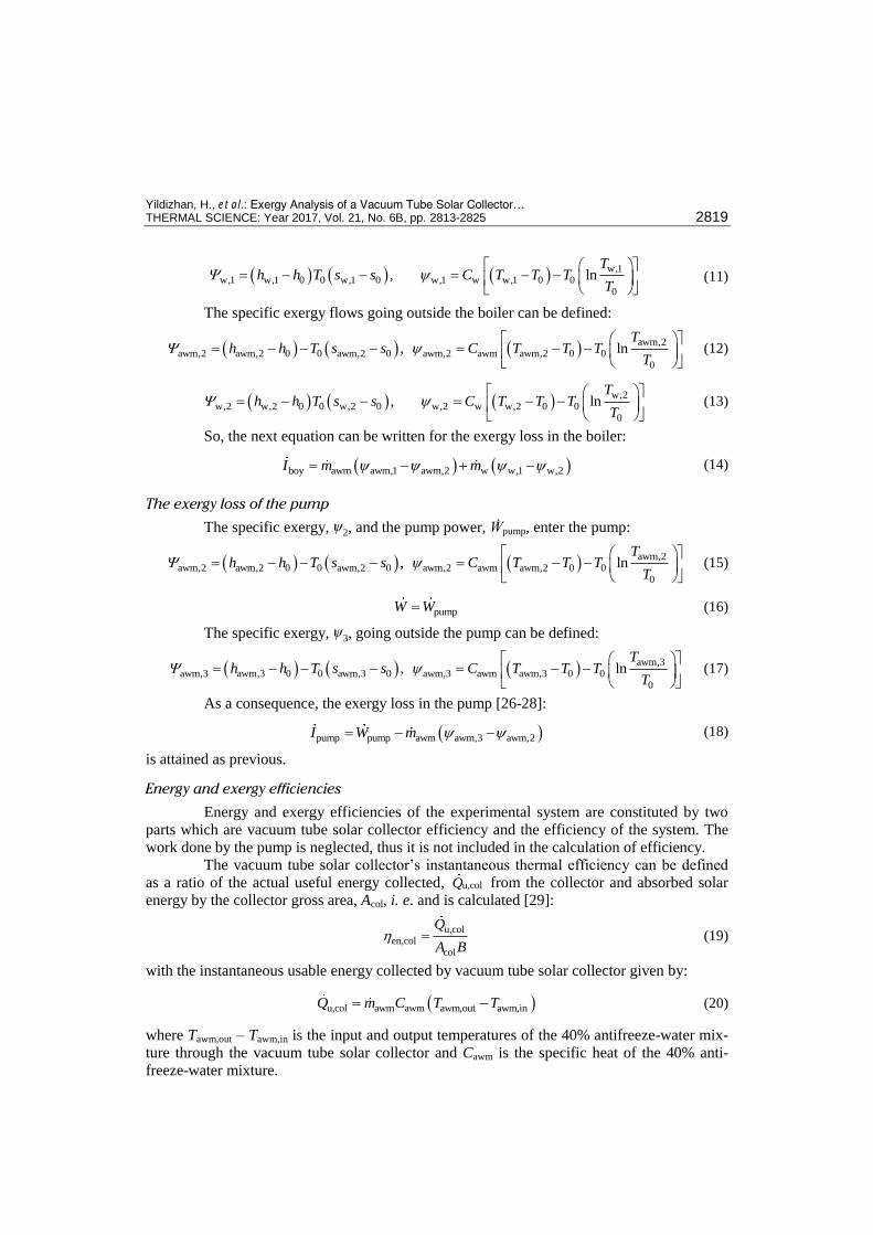
(11)
The specific exergy flows going outside the boiler can be defined:
awm,2awm,2 awm,2 0 0 awm,2 0 awm,2 awm awm,2 0 0
0
, lnT
h h T s s C T T TT
(12)
w,2w,2 w,2 0 0 w,2 0 w,2 w w,2 0 0
0
, lnT
h h T s s C T T TT
(13)
So, the next equation can be written for the exergy loss in the boiler:
boy awm awm,1 awm,2 w w,1 w,2I m m (14)
The exergy loss of the pump
The specific exergy, ѱ2, and the pump power, Ẇpump, enter the pump:
awm,2awm,2 awm,2 0 0 awm,2 0 awm,2 awm awm,2 0 0
0
, lnT
h h T s s C T T TT
(15)
pumpW W (16)
The specific exergy, ѱ3, going outside the pump can be defined:
awm,3awm,3 awm,3 0 0 awm,3 0 awm,3 awm awm,3 0 0
0
, lnT
h h T s s C T T TT
(17)
As a consequence, the exergy loss in the pump [26-28]:
pump pump awm awm,3 awm,2I W m (18)
is attained as previous.
Energy and exergy efficiencies
Energy and exergy efficiencies of the experimental system are constituted by two
parts which are vacuum tube solar collector efficiency and the efficiency of the system. The
work done by the pump is neglected, thus it is not included in the calculation of efficiency.
The vacuum tube solar collector’s instantaneous thermal efficiency can be defined
as a ratio of the actual useful energy collected, u,colQ from the collector and absorbed solar
energy by the collector gross area, Acol, i. e. and is calculated [29]:
u,col
en,colcol
Q
A B (19)
with the instantaneous usable energy collected by vacuum tube solar collector given by:
u,col awm awm awm,out awm,inQ m C T T (20)
where Tawm,out – Tawm,in is the input and output temperatures of the 40% antifreeze-water mix-
ture through the vacuum tube solar collector and Cawm is the specific heat of the 40% anti-
freeze-water mixture.
Yildizhan, H., et al.: Exergy Analysis of a Vacuum Tube Solar Collector… 2820 THERMAL SCIENCE: Year 2017, Vol. 21, No. 6B, pp. 2813-2825
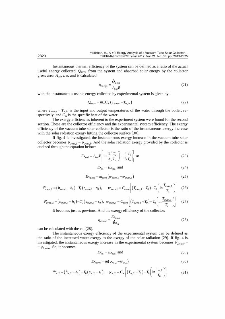
Instantaneous thermal efficiency of the system can be defined as a ratio of the actual
useful energy collected u,sysQ from the system and absorbed solar energy by the collector
gross area, Acol, i. e. and is calculated:
u,sys
en,syscol
Q
A B (21)
with the instantaneous usable energy collected by experimental system is given by:
u,sys w w w,out w,inQ m C T T (22)
where Tw,out – Tw,in is the input and output temperatures of the water through the boiler, re-
spectively, and Cw is the specific heat of the water.
The exergy efficiencies inherent to the experiment system were found for the second
section. These are the collector efficiency and the experimental system efficiency. The exergy
efficiency of the vacuum tube solar collector is the ratio of the instantaneous exergy increase
with the solar radiation exergy hitting the collector surface [30].
If fig. 4 is investigated, the instantaneous exergy increase in the vacuum tube solar
collector becomes ѱawm,1 – ѱawm,3. And the solar radiation exergy provided by the collector is
attained through the equation below:
4
0 0rad col
sr sr
1 41
3 3
T TEx A B
T T
so (23)
in radEx Ex and (24)
u,col awm awm,1 awm,3Ex m (25)
awm,1awm,1 awm,1 0 0 awm,1 0 awm,1 awm awm,1 0 0
0
, lnT
h h T s s C T T TT
(26)
awm,3awm,3 awm,3 0 0 awm,3 0 awm,3 awm awm,3 0 0
0
, lnT
h h T s s C T T TT
(27)
It becomes just as previous. And the exergy efficiency of the collector:
u,col
ex,colin
Ex
Ex (28)
can be calculated with the eq. (28).
The instantaneous exergy efficiency of the experimental system can be defined as
the ratio of the increased water exergy to the exergy of the solar radiation [29]. If fig. 4 is
investigated, the instantaneous exergy increase in the experimental system becomes ѱ2water – – ѱ
1water. So, it becomes:
in radEx Ex and (29)
u,sys w,2 w,1Ex m (30)
w,2
w,2 w,2 0 0 w,2 0 w,2 w w,2 0 00
, lnT
h h T s s C T T TT
(31)

Yildizhan, H., et al.: Exergy Analysis of a Vacuum Tube Solar Collector… THERMAL SCIENCE: Year 2017, Vol. 21, No. 6B, pp. 2813-2825 2821
w,1w,1 w,1 0 0 w,1 0 w,1 w w,1 0 0
0
, lnT
h h T s s C T T TT
(32)
and the system efficiency becomes:
u,sys
ex,sysin
Ex
Ex (33)
Case study
Performance of the experimental set-up was observed for five days. Experiments
were conducted between 8:00 a. m. and 5:30 p. m.. Measurements were recorded in every 30
minutes. Water temperature at input and output of the collector, feed water temperature at
input and output of the boiler, water temperature at input and output of the pump, ambient
temperature, mass flow rates, and solar radiation on the inclined surface were recorded. Daily
average of the recorded values was used to investigation of performance of the experimental
set-up. The data obtained from the tests in the solar water heating system are based on August
2012 from 08:00 a. m. to 5:00 p. m., as listed in tab. 5.
Table 5. The input and output temperatures of the 40% antifreeze-water mixture through the vacuum tube solar collector
Date Local time, [hour] Temperature, [oC]
Inlet Outlet
20.08.2012
08:00 42.6 50.4
10:00 58.2 70.9
12:00 63.5 77.2
14:00 64.1 77.2
16:00 57.1 66.3
17:30 40.2 42.5
21.08.2012
08:00 42.2 50
10:00 57.8 70.9
12:00 62.6 76.7
14:00 63.1 76.2
16:00 55.4 64.9
17:30 38.9 41.5
22.08.2012
08:00 42.4 50.2
10:00 58 70.7
12:00 63.2 76.9
14:00 63.8 77
16:00 56.8 66.1
17:30 40 42.3
23.08.2012
08:00 42.2 49.7
10:00 58.7 71.3
12:00 63.9 77.5
14:00 64 77.1
16:00 56.7 65.6
17:30 40.1 42.8
24.08.2012
08:00 42.5 50.1
10:00 58.2 70.6
12:00 63 76.8
14:00 63.9 77.3
16:00 55.4 64.5
17:30 40 42.7
Yildizhan, H., et al.: Exergy Analysis of a Vacuum Tube Solar Collector… 2822 THERMAL SCIENCE: Year 2017, Vol. 21, No. 6B, pp. 2813-2825
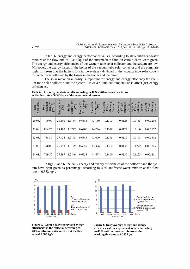
In tab. 6, energy and exergy performance values, according to 40% antifreeze-water
mixture at the flow rate of 0.383 kg/s of the intermediate fluid on certain dates were given.
The energy and exergy efficiencies of the vacuum tube solar collector and the system are low.
Moreover, the exergy losses of the boiler of the vacuum tube solar collector and the pump are
high. It is seen that the highest loss in the system calculated in the vacuum tube solar collec-
tor, which was followed by the losses in the boiler and the pump.
The solar radiation intensity is important for energy and exergy efficiency the vacu-
um tube solar collector and the system. However, ambient temperature is affect just exergy
efficiencies.
Table 6. The exergy analysis results according to 40% antifreeze-water mixture at the flow rate of 0.383 kg/s of the experimental system
Dat
e
(Yea
r 2
01
2)
So
lar
rad
iati
on
inte
nsi
ty
[Wm
–2]
Tem
per
atu
re
[oC
]
Bo
iler
ex
erg
y l
oss
[k
W]
Ex
ergy
lo
ss
of
the
pu
mp
[k
W]
Co
llec
tor
exer
gy l
oss
[k
W]
Co
llec
tor
1st l
aw
effi
cien
cy
[en
erg
y]
Co
llec
tor
2nd l
aw
effi
cien
cy
[ex
erg
y]
Sy
stem
1
st l
aw
effi
cien
cy
[en
erg
y]
Sy
stem
2
nd l
aw
effi
cien
cy
[ex
erg
y]
20.08. 799.00 28.190 1.3164 0.6386 143.130 0.1303 0.0128 0.1135 0.003206
21.08. 804.75 28.400 1.3247 0.6406 144.726 0.1378 0.0127 0.1180 0.003072
22.08. 788.50 27.924 1.3175 0.6383 143.099 0.1375 0.0132 0.1198 0.003312
23.08. 790.00 26.798 1.3179 0.6355 143.396 0.1382 0.0135 0.1272 0.003816
24.08. 769.50 27.497 1.2849 0.6534 141.498 0.1400 0.0130 0.1223 0.003111
In figs. 5 and 6, the daily energy and exergy efficiencies of the collector and the sys-
tem have been given as percentage, according to 40% antifreeze-water mixture at the flow
rate of 0.383 kg/s.
Figure 5. Average daily energy and exergy efficiencies of the collector according to
40% antifreeze-water mixture at the flow rate of 0.383 kg/s
Figure 6. Daily average energy and exergy efficiencies of the experiment system according
to 40% antifreeze-water mixture at the working flow rate of 0.383 kg/s

Yildizhan, H., et al.: Exergy Analysis of a Vacuum Tube Solar Collector… THERMAL SCIENCE: Year 2017, Vol. 21, No. 6B, pp. 2813-2825 2823
When fig. 5 is investigated, it is seen that there are great differences between the en-
ergy and exergy efficiencies of the vacuum tube solar collector. This situation is also seen in
the experimental system.
Conclusions and suggestions
We have presented exergetic aspects of a vacuum tube solar collector system having
ındirect working principle in general and have evaluated the performance of a vacuum tube
solar collector system having indirect working principle. The experimental values are utilized
in the analysis.
We can extract some concluding remarks from this study as follows.
Energy and exergy efficiencies of experimental set-up and evacuated tube solar collector
are strongly influenced from solar irradiation. On the other hand ambient temperature has
dominant effect on the exergy efficiency of the experimental set-up and evacuated tube
solar collector.
At the exergy analysis duration of the experiment, it has been ascertained that the most
exergy loss among the processes of the system was in the vacuum tube solar collectors.
The average exergy loss in the vacuum tube collectors is approximately 143 kW. The ex-
ergy loss of the collector is over %90 in the total exergy loss. Respectively, boiler and
pump followed the vacuum tube solar collectors. Average exergy loss of the boiler is
around 1.3 kW and average exergy loss of the pump is approximately 0.64 kW.
The obtained data were compared with direct operating principle of the system re-
sults in the literature. Energy and exergy efficiencies of the vacuum tube solar collectors,
which indirect operating principle, are lower than direct system working solar collectors. Av-
erage energy and exergy efficiencies of the experimental system founded 12% and 0.3%,
respectively, (tab. 6). The average energy and exergy efficiencies of the vacuum tube solar
collectors founded 13.6% and 1.3% (tab. 6). Therefore, in order to make the energy and exer-
gy efficiencies of both experimental system and the vacuum tube solar collector at optimum
levels. It is necessary that the collector surface area must be reduced in this kind of solar pow-
er systems and in order to let the intermediate fluid circulating between the collector and the
boiler. It is necessary that the volume of the boiler and the surface area of the serpentine
which is in the boiler must be increased. So, with the increase in boiler’s volume and the ser-
pentine surface within the boiler the collector heat difference increase. In this case the vacuum
tube solar collectors will have a positive impact to increase the energy and exergy efficien-
cies.
Nomenclature
A – area, [m2] B – incidence of solar radiation on a unit area
of surface, [kWm–2] Cp – specific heat at the
constant pressure, [kJkg–1K–1] Ex – exergy rate, [kW] h – specific enthalpy, [kJkg–1] İ – rate of irreversibility, [kW] ṁ – mass flow rate, [kgs–1] Q – heat transfer rate, [kW] s – specific entropy, [kJkg–1K–1] T – temperature, [K or oC] Ẇ – work rate or power, [kW]
Greek symbols
η – efficiency Ψ – specific exergy, [kJkg–1]
Subscipts
awm – 40% antifreeze-water mixture boy – boiler col – collector dest – destroyed (destruction) en – energy ex – exergy in – inlet

Yildizhan, H., et al.: Exergy Analysis of a Vacuum Tube Solar Collector… 2824 THERMAL SCIENCE: Year 2017, Vol. 21, No. 6B, pp. 2813-2825
k – location out – outlet rad – radiation sr – solar radiation
sys – experimental system u – useful w – water 0 – dead (reference) state
References
[1] Johari, D., et al., Study of Solar Water Heaters Based on Exergy Analysıs, Proceedings, National Con-ference on Trends and Advances in Mechanical Engineering, Faridabad, Haryana, India, 2012
[2] ***, ASHRAE, Handbook of HVAC Applications, Vol. 30, 1995, Atlanta, Geo., USA [3] He, Z. N., et al., A Comparison of Optical Performance between Evacuated Collector Tubes with Flat
and Semi-Cylindric Absorbers, Solar Energy, 60 (1997), 2, pp 109-117 [4] Kim, J. T., et al., The Performance Simulation of All Glass Vacuum Tubes with Coaxial Fluid Conduit,
International Communications in Heat and Mass Transfer, 34 (2007), 5, pp. 587-597 [5] Shah, L. J., Furbo, S., Vertical Evacuated Tubular-Collectors Utilizing Solar Radiation from All Direc-
tions, Applied Energy, 78 (2004), 4, pp. 371-395 [6] Morrison, G. L., et al., Measurement and Simulation of Flow Rate in a Water-in-Glass Evacuated Tube
Solar Water Heater, Solar Energy, 78 (2005), 2, pp. 257-267 [7] Kim, Y., Seo, T., Thermal Performances Comparisons of the Glass Evacuated Tube Solar Collectors
with Shapes of Absorber Tube, Renewable Energy, 32 (2007), 5, pp. 772-795 [8] Han, H., et al., A Three-Dimensional Performance Analysis of All-Glass Vacuum Tubes with Coaxial
Fluid Conduit, International Communications in Heat and Mass Transfer, 35 (2008), 5, pp. 589-596 [9] Ma, L., et al., Thermal Performance Analysis of the Glass Evacuated Tube Solar Collector with U-Tube,
Building and Environment, 45 (2010), 9, pp. 1959-1967 [10] Liang, R., et al., Theoretical and Experimental Investigation of The Filled-Type Evacuated Tube Solar
Collector with U Tube, Solar Energy, 85 (2011), 9, pp. 1735-1744 [11] Hepbasli, A., The Necessity and Application of Exergy Analysis in Systems with Solar Energy, Pro-
ceedings, Chamber of Mechanical Engineers, Symposium and Exhibition of Solar Energy Systems, Mer-sin, Turkey, 2003, Vol. 1, pp. 80-87
[12] Xiaowu, W., Hua, B., Exergy Analysis of Domestic-Scale Solar Water Heaters, Renewable and Sustain-able Energy Reviews, 9 (2005), 6, pp. 638-645
[13] Saidur, R., et al., Exergy Analysis of Solar Energy Applications, Renewable and Sustainable Energy Reviews, 16 (2012), 1, pp. 350-356
[14] Gunerhan, H., Hepbasli, A., Exergetic Modelling and Performance Evaluation of Solar Water Heating Systems for Building Applications, Energy and Buildings, 39 (2007), 5, pp. 509-516
[15] Badescu, V., Optimal Control of Flow in Solar Collectors for Maximum Exergy Extraction, Internation-al Journal of Heat and Mass Transfer, 50 (2007), 21-22, pp. 4311-4322
[16] Farahat, S., et al., Exergetic Optimization of Flat Plate Solar Collectors, Renewable Energy, 34 (2009), 4, pp. 1169-1174
[17] Jafarkazemi, F., Ahmadifard, E., Energetic and Exergetic Evaluation of Flat Plate Solar Collectors, Renewable Energy, 56 (2013), Aug., pp. 55-63
[18] Luminosua, I., Farab, L., Determination of the Optimal Operation Mode of a Flat Solar Collector by Exergetic Analysis and Numerical Simulation, Energy, 30 (2005), 5, pp. 731-747
[19] Pei, G., et al., Comparative Experimental Analysis of the Thermal Performance of Evacuated Tube Solar Water Heater Systems with and without a Mini Compound Parabolic Concentrating (CPC) Reflector (C < 1) , Energies, 5 (2012), 4, pp. 911-924
[20] Yıldızhan, H., Exergy Analysis of Vacumm Tube Solar Collectors with a Boiler According to Different Parameters, Ph. D. Thesis, Gazi University, Ankara, Turkey, 2013
[21] Cengel, Y. A., Boles, M. A., Thermodynamics: An Engineering Approach, McGraW-Hill, New York, USA, 1994, pp. 67-68
[22] Szargut, J., Exergy Method: Technical and Ecological Applications, Boston: WIT Press, Southampton, UK, 2005, pp. 50-52
[23] Hepbasli, A., A Key Review on Exergetic Analysis and Assessment of Renewable Energy Resources for a Sustainable Future, Renewable and Sustainable Energy Reviews, 12 (2008), 3, pp. 593-661
[24] Petela, R., Exergy of Undiluted Thermal Radiation, Solar Energy, 74 (2003), 6, pp. 469-488 [25] Hepbasli, A., et al., Exergy Analysis of Heat Pump Systems for Residential Applications, Journal of
Turkish Plumbing Engineers Chamber, 44 (2006), pp. 18-24

Yildizhan, H., et al.: Exergy Analysis of a Vacuum Tube Solar Collector… THERMAL SCIENCE: Year 2017, Vol. 21, No. 6B, pp. 2813-2825 2825
[26] Dincer, I., Rosen, M. A., Exergy, Energy, Environment and Sustainable Development, Elsevier, New York, USA, 2013, pp. 104-105
[27] Yildirim, D., Ozgener, L., Thermodynamics and Exergoeconomic Analysis of Geothermal Power Plants, Renewable and Sustainable Energy Reviews, 16 (2012), 8, pp. 6438-6454
[28] Ozturk, H. H., Experimental Determination of Energy and Exergy Efficiency of the Solar Parabolic-Cooker, Solar Energy, 77 (2004),1, pp. 67-71
[29] Singh, N., et al., Exergetic Analysis of a Solar Thermal Power System, Renewable Energy, 19 (2000), 1-2, pp. 135-143
Paper submitted: September 5, 2015 © 2017 Society of Thermal Engineers of Serbia. Paper revised: December 12, 2015 Published by the Vinča Institute of Nuclear Sciences, Belgrade, Serbia. Paper accepted: December 31, 2015 This is an open access article distributed under the CC BY-NC-ND 4.0 terms and conditions.