
Exergy Analysis of a Syngas-Fueled Combined Cycle with ...
25
OPEN ACCESS www.sciforum.net/conference/ecea-2 Conference Proceedings Paper – Entropy Exergy Analysis of a Syngas-Fueled Combined Cycle with Chemical-Looping Combustion and CO 2 sequestration Álvaro Urdiales 1 , Ángel Jiménez 1, *, Javier Rodríguez 1 and Rafael Nieto 1 1 Department of Energy Engineering, ETSII, Technical University of Madrid. José Gutiérrez Abascal, 2, 28006, Madrid, Spain * Author to whom correspondence should be addressed; e-mail: [email protected], tel.: +34 91 336 4262, fax: +34 91 336 4263 Published: 5 November 2015 Abstract: Fossil fuels are still needed extensively for power generation. Nevertheless, it would be feasible to attain a considerable reduction of greenhouse gas emissions to the atmosphere derived from this activity capturing the CO 2 produced by fossil fuels oxidation. The chemical-looping combustion (CLC) technique is based on a chemical intermediate agent which gets oxidized in an air reactor and is then conducted to a separated fuel reactor where it oxidizes the fuel in turn. Thus, the oxidation products CO 2 and H 2 O are obtained in an output flow in which the only non-condensable gas is CO 2 , allowing the subsequent sequestration of CO 2 without energy penalty. Furthermore, with shrewd configurations a lower exergy destruction in the combustion chemical transformation can be achieved. This paper focus on a Second-Law analysis of a CLC combined cycle power plant with CO 2 sequestration using syngas from coal and biomass gasification as fuel. The key thermodynamic parameters are optimized via the exergy method. The proposed power plant configuration is compared with an equivalent gas turbine system based on a conventional combustion, finding a notable increase of the power plant efficiency. Also, the sensitivity of the results to syngas composition is investigated by considering different H 2 -content fuels. Keywords: chemical-looping combustion; exergy analysis; Second-Law efficiency; efficient system for power generation; carbon capture and storage; gas turbine system; synthesis gas PACS classifications: 88.05.Bc,88.05.De
Transcript of Exergy Analysis of a Syngas-Fueled Combined Cycle with ...

OPEN ACCESS
www.sciforum.net/conference/ecea-2Conference Proceedings Paper – Entropy
Exergy Analysis of a Syngas-Fueled Combined Cycle withChemical-Looping Combustion and CO2 sequestrationÁlvaro Urdiales1, Ángel Jiménez1,*, Javier Rodríguez1 and Rafael Nieto1
1 Department of Energy Engineering, ETSII, Technical University of Madrid.José Gutiérrez Abascal, 2, 28006, Madrid, Spain
* Author to whom correspondence should be addressed;e-mail: [email protected], tel.: +34 91 336 4262, fax: +34 91 336 4263
Published: 5 November 2015
Abstract: Fossil fuels are still needed extensively for power generation. Nevertheless,it would be feasible to attain a considerable reduction of greenhouse gas emissions to theatmosphere derived from this activity capturing the CO2 produced by fossil fuels oxidation.The chemical-looping combustion (CLC) technique is based on a chemical intermediateagent which gets oxidized in an air reactor and is then conducted to a separated fuelreactor where it oxidizes the fuel in turn. Thus, the oxidation products CO2 and H2Oare obtained in an output flow in which the only non-condensable gas is CO2, allowingthe subsequent sequestration of CO2 without energy penalty. Furthermore, with shrewdconfigurations a lower exergy destruction in the combustion chemical transformation can beachieved. This paper focus on a Second-Law analysis of a CLC combined cycle power plantwith CO2 sequestration using syngas from coal and biomass gasification as fuel. The keythermodynamic parameters are optimized via the exergy method. The proposed power plantconfiguration is compared with an equivalent gas turbine system based on a conventionalcombustion, finding a notable increase of the power plant efficiency. Also, the sensitivity ofthe results to syngas composition is investigated by considering different H2-content fuels.
Keywords: chemical-looping combustion; exergy analysis; Second-Law efficiency; efficientsystem for power generation; carbon capture and storage; gas turbine system; synthesis gas
PACS classifications: 88.05.Bc,88.05.De
Entropy 2015, xx 2
1. Introduction
The carbon capture and storage (CCS) is seen as a potential option for mitigation of the greenhousegas (GHG) emissions produced by power generation based on fossil fuels combustion. Thus, it couldhelp during the transitional period of development of new and clean sources of energy.
Several separation methods have been proposed e.g. chemical absorption or adsorption, separation bymembrane or cryogenic separation among others. For instance, [1] describes a capture method via aminechemical absorption in the case of a “post-combustion” strategy. Nevertheless, the high energy penaltyinvolved in the separation of carbon dioxide from a gaseous stream seriously questions the viability ofCCS in thermal power plants in practice. Regarding thermochemical gasification of solid fuels, theyare decarbonized to a mixture of mainly hydrogen, carbon monoxide and carbon dioxide (synthesisgas or merely syngas). In this case a “pre-combustion” strategy is preferred, since CO2 is quite moreconcentrated in the syngas than it is in the air after combustion. The energy penalty is lower but stillimportant. Several methods are assessed by [2]. Another interesting option is the “oxy-combustion”strategy, which consists in burning the fuel with pure oxygen instead of with air. Consequently aneasy separation of CO2 is obtained by cooling the combustion gases and condensing water. Interestingenergy savings strategies have been proposed to reduce the energy cost [3], but still a significant energyconsumption takes place in the oxygen separation from air.
The chemical-looping combustion (CLC) is an alternative combustion system proposed by [4]. A lotof research has been carried out and many other contributions have given rise to the progress of thistechnology. Because of its interest in the field of gas turbines, most studies related to CLC have beendevoted to the study of methane as fuel. Other alternative fuels, e.g. methanol, also have been suggestedand studied [5]. The interest of other fuels is of interest as well. In particular synthesis gas deserves someattention. Previous works [6],[7] give a very interesting insight on CLC systems and a thermodynamicanalysis of a syngas fueled gas turbine cycle. A more recent job [8], provides an exhaustive energeticanalysis of a syngas fueled combined cycle with CCS from a First-Law point of view. The scope of thepresent work is to complement that analysis with a Second-Law approach in order to provide a furtherunderstanding of such systems. The overall exergetic performance of a CLC combined cycle power plantwith integrated CO2 capture and fueled by syngas is studied. Details on the behavior of the proposedpower plant in a range of operating conditions are provided. In addition, it has been found of interestto compare the proposed CLC-based system with a conventional gas turbine cycle. Finally, the highercomplexity of CLC systems makes them more sensitive to changes in the fuel chemical composition.For this reason, different syngas compositions have been considered and studied.
1.1. Chemical-looping combustion: idea and objective
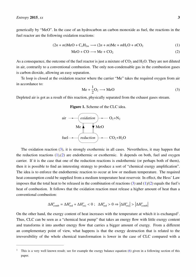
The CLC concept is presented schematically in Fig. 1. Combustion takes place in two steps by way ofan intermediate agent, an oxygen carrier, so that air and fuel never get in contact. Two different reactorsare used. In the air reactor (oxidation reactor) the oxygen carrier is oxidized in presence of air. Then,it is transferred to the fuel reactor (reduction reactor) where the oxygen is interchanged: the carrier isreduced and the fuel is oxidized. Finally, the reduced oxygen carrier is redirected again to the air reactorto close the loop. As discussed in section 2.2, the typical oxygen carrier are metal oxides. We denote it
Entropy 2015, xx 3
generically by “MeO”. In the case of an hydrocarbon an carbon monoxide as fuel, the reactions in thefuel reactor are the following oxidation reactions:
(2n + m)MeO + CnH2m −→ (2n + m)Me + mH2O + nCO2 (1)
MeO + CO −→ Me + CO2 (2)
As a consequence, the outcome of the fuel reactor is just a mixture of CO2 and H2O. They are not dilutedin air, contrarily to a conventional combustion. The only non-condensable gas in the combustion gasesis carbon dioxide, allowing an easy separation.
Te loop is closed at the oxidation reactor where the carrier “Me” takes the required oxygen from airin accordance to:
Me +12
O2 −→ MeO (3)
Depleted air is got as a result of this reaction, physically separated from the exhaust gases stream.
Figure 1. Scheme of the CLC idea.
��
��- -
��
��- -
Me N H MeO
air oxidation O2+N2
fuel reduction CO2+H2O
The oxidation reaction (3), it is strongly exothermic in all cases. Nevertheless, it may happen thatthe reduction reactions (1),(2) are endothermic or exothermic. It depends on both, fuel and oxygencarrier. If it is the case that one of the reduction reactions is endothermic (or perhaps both of them),then it is possible to find an interesting strategy to produce a sort of “chemical exergy amplification”.The idea is to enforce the endothermic reaction to occur at low or medium temperature. The requiredheat consumption could be supplied from a medium temperature heat reservoir. In effect, the Hess’ Lawimposes that the total heat to be released in the combination of reactions (3) and (1)/(2) equals the fuel’sheat of combustion. It follows that the oxidation reaction must release a higher amount of heat than aconventional combustion:
∆H◦comb = ∆H◦red + ∆H◦oxi < 0 ; ∆H◦red > 0⇒∣∣∣∆H◦oxi
∣∣∣ > ∣∣∣∆H◦comb
∣∣∣On the other hand, the exergy content of heat increases with the temperature at which it is exchanged1.Thus, CLC can be seen as a “chemical heat pump” that takes an energy flow with little exergy contentand transforms it into another energy flow that carries a bigger amount of exergy. From a differentan complementary point of view, what happens is that the exergy destruction that is related to theirreversibility of the whole chemical transformation is lower in the case of CLC compared with a
1 This is a very well known result; see for example the exergy balance equation (6) given in a following section of thispaper.

Entropy 2015, xx 4
conventional combustion. A detailed theoretical analysis of this type of “exergy amplification” is givenby [9].
The interesting point is that in the case of a gas turbine system, the gases at turbine outlet can be usedas the medium temperature heat source that provides the required heat to the reduction reactor.
In addition, and more importantly, the separation of CO2 generated as a consequence of fuel’soxidation is “energy-free”. As described previously, a mixture of mainly carbon dioxide and water isgot and a simple condensation of water allows an easy sequestration of CO2. This was the case forthe “oxy-combustion” technique mentioned above, but CLC avoids any energy penalty due to both,separation of the carbon dioxide from other gases and also separation of the oxygen from air. Theprevious two aspects, and particularly the last one, are the major advantages of CLC. Moreover, it maybe of interest to remark that the separation of fuel and air into different reactors avoids the existence offlames, leading to less NOx formation [10].
The CLC reactors shown in Fig. 1 can be materialized in several ways [11]. The approach mostfrequently proposed are fluidized-bed reactors. The metal oxides are found in the form of fine “floating”particles. The size of particles must be chosen in order to ensure a sufficient contact area to provideoptimal conditions for the chemical reactions in both reactors. Catalysis might be necessary to improvethe chemical kinetics, but this point is out of the scope of this work.
2. Description of the study
2.1. Proposed CLC-based gas turbine cycle
The proposed CLC combined cycle with carbon dioxide sequestration, depicted in Fig. 2, is takenfrom Ref. [8] and is based on prior ideas suggested by [5] and [6]. A further discussion on theadvantages of this configuration can be found in [8]. The thermodynamic parameters of the cycle havebeen maintained as given by [8]:
• Ambient conditions: 15 ◦C (288.15 K), 1 atm (101.325 kPa), 60% RH (relative humidity).
• Fuel conditions: 153.4 ◦C (426.58 K), 27.24 bar.
• Pressure drop at the air filter: 1 kPa.
• Isentropic efficiency of compressors: 0.845.
• Isentropic efficiency of gas turbines: 0.895.
• Pressure drop in reactors: 4%
• Heat losses in reactors: 0.5% in the oxidation reactor, 0.2% in the reduction reactor.
• Pressure drop in HRSG: 3.5%.
• Pressure drop in other heat exchangers: 1%.

Entropy 2015, xx 5
• Pinch point in heat exchanges: 10 ◦C in gas–gas exchanges, 50 ◦C in the air pre-heater.
• Temperature of exhaust gases after HRSG: dew point and never under 90 ◦C (363.15 K).
• Final pressure for CO2 storage: 85 bar.
Figure 2. CLC-based combined cycle with CO2 sequestration and storage.
For the steam cycle (not included in Fig. 2) a one-level pressure conventional steam cycle has beenconsidered. Condensation pressure is fixed at 0.07 bar, pressure at the boiler economizer inlet is set to76 bar and steam pressure at the boiler outlet is 67 bar. The steam temperature at the boiler output isassumed 20 ◦C lower than the exhaust gas temperature and never higher than 545 ◦C (818.15 K).
The above values are considered to be reasonable and within the common range in combined cycles[5],[11],[12]. Fuel conditions have been taken from available preliminary data on gasification processes[13]. Regarding the final compression pressure for CO2, it allows transport or storage as a supercriticalfluid with high density. The particular figure 85 bar used here is taken from [11]. The compression setuphas been modeled to take place in two stages with the same compression ratio, giving:
p17 =√
p15 p18
The rest of the free parameters of the cycle has been set to their optimal values from the point of viewof power production. These optimal values are adjusted as a function of GT1 turbine inlet temperature(TIT) and the reactors pressure (pr).
The overall exergetic performance of the power plant showed in Fig. 2 is evaluated after analysis andoptimization.
Entropy 2015, xx 6
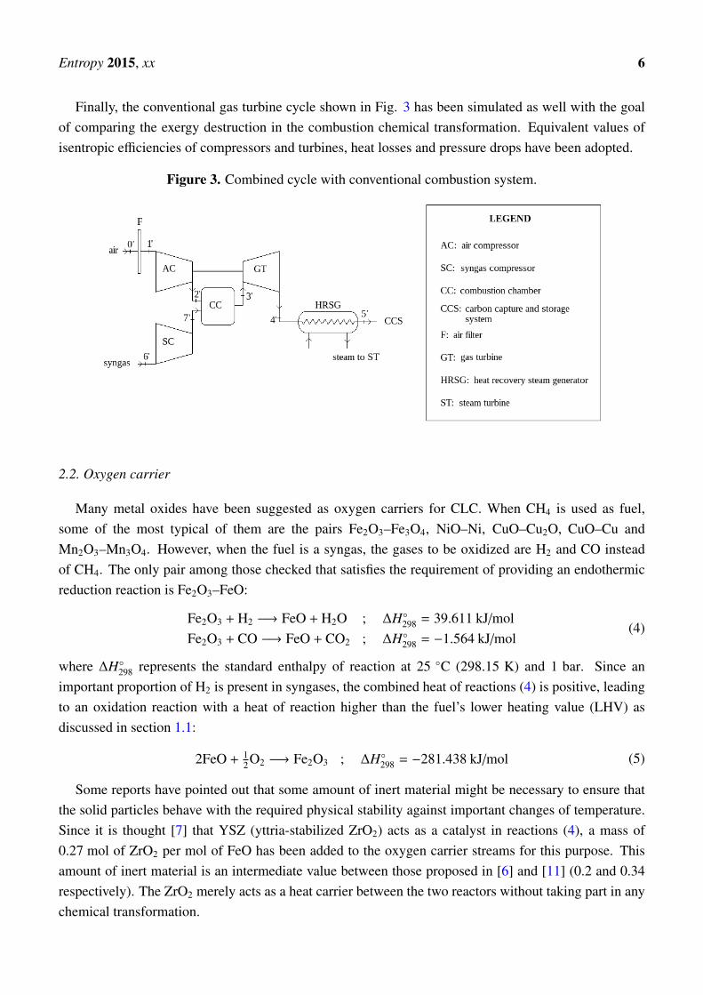
Finally, the conventional gas turbine cycle shown in Fig. 3 has been simulated as well with the goalof comparing the exergy destruction in the combustion chemical transformation. Equivalent values ofisentropic efficiencies of compressors and turbines, heat losses and pressure drops have been adopted.
Figure 3. Combined cycle with conventional combustion system.
2.2. Oxygen carrier
Many metal oxides have been suggested as oxygen carriers for CLC. When CH4 is used as fuel,some of the most typical of them are the pairs Fe2O3–Fe3O4, NiO–Ni, CuO–Cu2O, CuO–Cu andMn2O3–Mn3O4. However, when the fuel is a syngas, the gases to be oxidized are H2 and CO insteadof CH4. The only pair among those checked that satisfies the requirement of providing an endothermicreduction reaction is Fe2O3–FeO:
Fe2O3 + H2 −→ FeO + H2O ; ∆H◦298 = 39.611 kJ/molFe2O3 + CO −→ FeO + CO2 ; ∆H◦298 = −1.564 kJ/mol
(4)
where ∆H◦298 represents the standard enthalpy of reaction at 25 ◦C (298.15 K) and 1 bar. Since animportant proportion of H2 is present in syngases, the combined heat of reactions (4) is positive, leadingto an oxidation reaction with a heat of reaction higher than the fuel’s lower heating value (LHV) asdiscussed in section 1.1:
2FeO + 12O2 −→ Fe2O3 ; ∆H◦298 = −281.438 kJ/mol (5)
Some reports have pointed out that some amount of inert material might be necessary to ensure thatthe solid particles behave with the required physical stability against important changes of temperature.Since it is thought [7] that YSZ (yttria-stabilized ZrO2) acts as a catalyst in reactions (4), a mass of0.27 mol of ZrO2 per mol of FeO has been added to the oxygen carrier streams for this purpose. Thisamount of inert material is an intermediate value between those proposed in [6] and [11] (0.2 and 0.34respectively). The ZrO2 merely acts as a heat carrier between the two reactors without taking part in anychemical transformation.
Entropy 2015, xx 7
2.3. Fuels under study
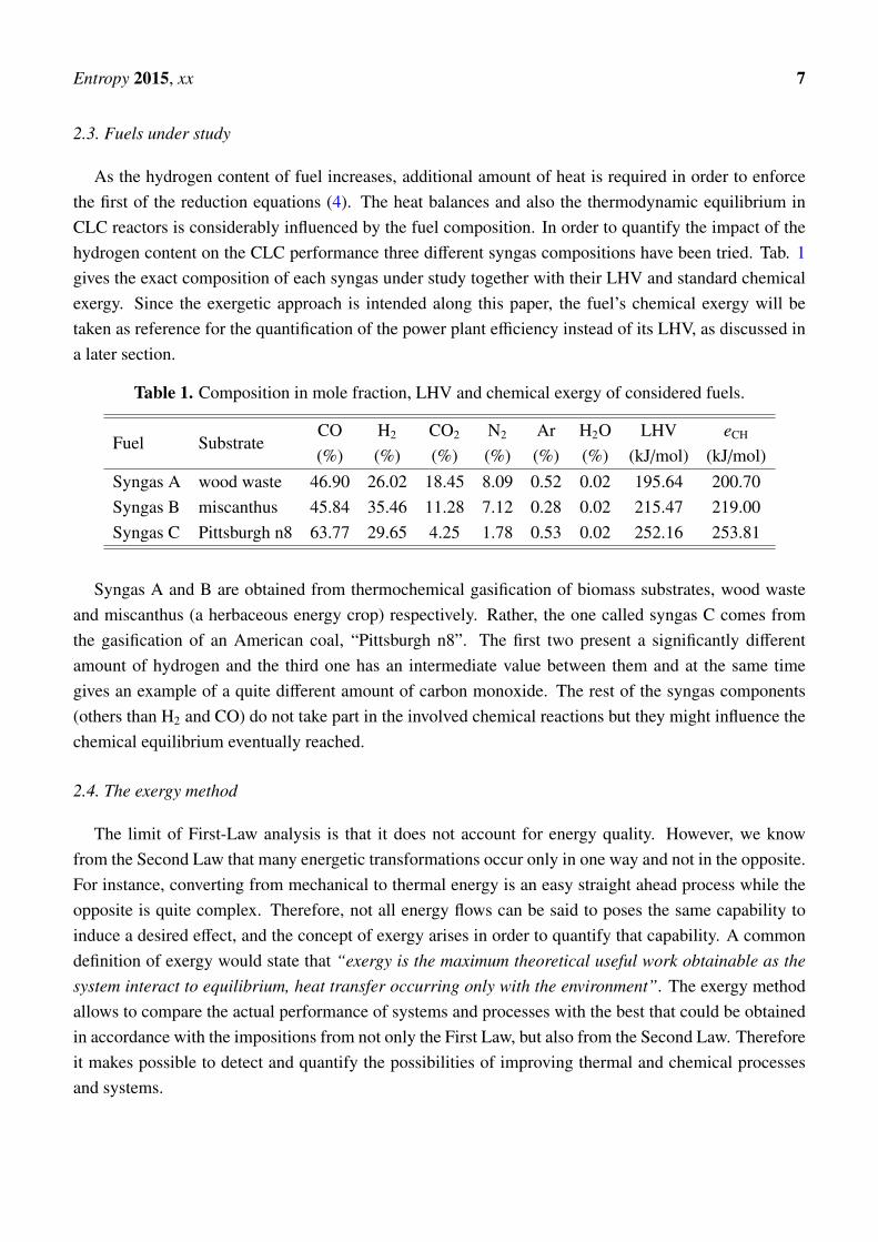
As the hydrogen content of fuel increases, additional amount of heat is required in order to enforcethe first of the reduction equations (4). The heat balances and also the thermodynamic equilibrium inCLC reactors is considerably influenced by the fuel composition. In order to quantify the impact of thehydrogen content on the CLC performance three different syngas compositions have been tried. Tab. 1gives the exact composition of each syngas under study together with their LHV and standard chemicalexergy. Since the exergetic approach is intended along this paper, the fuel’s chemical exergy will betaken as reference for the quantification of the power plant efficiency instead of its LHV, as discussed ina later section.
Table 1. Composition in mole fraction, LHV and chemical exergy of considered fuels.
Fuel SubstrateCO H2 CO2 N2 Ar H2O LHV eCH
(%) (%) (%) (%) (%) (%) (kJ/mol) (kJ/mol)Syngas A wood waste 46.90 26.02 18.45 8.09 0.52 0.02 195.64 200.70Syngas B miscanthus 45.84 35.46 11.28 7.12 0.28 0.02 215.47 219.00Syngas C Pittsburgh n8 63.77 29.65 4.25 1.78 0.53 0.02 252.16 253.81
Syngas A and B are obtained from thermochemical gasification of biomass substrates, wood wasteand miscanthus (a herbaceous energy crop) respectively. Rather, the one called syngas C comes fromthe gasification of an American coal, “Pittsburgh n8”. The first two present a significantly differentamount of hydrogen and the third one has an intermediate value between them and at the same timegives an example of a quite different amount of carbon monoxide. The rest of the syngas components(others than H2 and CO) do not take part in the involved chemical reactions but they might influence thechemical equilibrium eventually reached.
2.4. The exergy method
The limit of First-Law analysis is that it does not account for energy quality. However, we knowfrom the Second Law that many energetic transformations occur only in one way and not in the opposite.For instance, converting from mechanical to thermal energy is an easy straight ahead process while theopposite is quite complex. Therefore, not all energy flows can be said to poses the same capability toinduce a desired effect, and the concept of exergy arises in order to quantify that capability. A commondefinition of exergy would state that “exergy is the maximum theoretical useful work obtainable as thesystem interact to equilibrium, heat transfer occurring only with the environment”. The exergy methodallows to compare the actual performance of systems and processes with the best that could be obtainedin accordance with the impositions from not only the First Law, but also from the Second Law. Thereforeit makes possible to detect and quantify the possibilities of improving thermal and chemical processesand systems.
Entropy 2015, xx 8
The expression of the exergy balance in an open system that describes a stationary process is givenby: ∑
i ∈ outputs
niei −∑
i ∈ inputs
niei = (Q − T0 Js) − W − I (6)
where
• n is the molar flow rate of a stream,
• e is the thermodynamic function of state flow exergy,
• Q is the heat flow rate exchanged by the system,
• Js is the entropy change rate associated with heat flow. For a single temperature system: Js =∫
dQT ;
for a multi-temperature system: Js =∑
k
∫dQkTk
.
• W is the mechanical power extracted from the system,
• I is the exergy destruction rate due to internal irreversibilities.
When a particular system exchanges heat that cannot be useful for a given purpose, i.e. the heatexchanges are merely heat losses to the environment, the heat flow terms in (6) can be included togetherwith the exergy destruction rate term in a total exergy loss rate term:
It = I − (Q − T0 Js)
Including this in the exergy balance:∑i ∈ outputs
niei −∑
i ∈ inputs
niei = −W − It (7)
The flow exergy function e represents the work per mol of substance that could be obtained from astream as the system comes to equilibrium whit the environment, involving any auxiliary devices. Everyimbalance between a stream and the environment may result in additional work to be generated. Ingeneral, the flow exergy is usually split in two terms:
• The so-called physical exergy involves thermal and mechanical imbalances with the environment.Disregarding kinetic and potential energy, this term can be shown to be equal to:
ePH = (h − h0) − T0(s − s0) (8)
As usual, h and s are the molar enthalpy and entropy of the stream respectively at its currenttemperature and pressure. The subscript ‘0’ represents the inert state, i.e. the referredthermodynamic function is evaluated considering that stream at ambient temperature and pressure.
• The so-called chemical exergy involves diffusive and chemical imbalances with the environment.The process by which equilibrium would be attained should happen at constant temperature equalto T0 (ambient temperature). It can be shown that the maximum theoretical work per mol ofsubstance produced in such a process is the opposite to the change of the specific Gibbs function:
wmaxT0
= −∆g
For a pure substance this can also be split into two terms:
Entropy 2015, xx 9
– The first one represents the change of the Gibbs function per mol of substance that happensin a degradation chemical transformation until chemical equilibrium with the environment:
∆g(1) = ∆G◦deg
For instance, in the case of a fuel, this would be referred to the combustion reaction. In thecase of substances present in the atmosphere in the same form, this term would not exist, e.g.nitrogen, oxygen, carbon dioxide, water, etc.
– Since this degradation chemical reaction should occur considering that the involved reactiveand products are taken from or given to the environment in a manner that the diffusiveequilibrium is also satisfied, a second term is needed to account for the change of the Gibbsfunction per mol of substance required for the chemical potentials of the substances to getequal to their actual values in the environment:
∆g(2) =∑
j
νdegj
(µenv
j − µpurej (T0, P0)
)where P0 is the ambient pressure, µ j represents the chemical potential of substance jinvolved in the degradation reaction (in pure form or its actual value in the environment)and νdeg
j denotes the stoichiometric coefficient of substance j in that reaction. For the caseof gases, usually the atmosphere is considered to behave as an ideal gas mixture, givingµenv
j − µpurej (T0, P0) = RT0 ln xatm
j , where xatmj is the mole fraction of gas j in the atmosphere.
As an example, for the case of methane, the degradation reaction would be the combustionCH4 + 2O2 → 2H2O + CO2 (with νdeg
O2= −2, νdeg
H2O = +2, νdegCO2
= +1), and:
∆g(2) = RT0 ln
(xatm
H2O
)2xatm
CO2(xatm
O2
)2
Thus, the chemical exergy of a pure substance is calculated as:
eCH = −∆G◦deg −∑
j
νdegj
(µenv
j − µpurej (T0, P0)
)(9)
There are several sources that tabulate standard chemical exergy of pure substances. In this workwe base the calculations in the values given by [14].
Finally, for a mixture of substances, the chemical exergy could be calculated as the averagechemical exergy of the individual components taking part, plus and additional term that accountsfor the change of the specific Gibbs function associated with the separation of the mixture intoits components in pure form at ambient temperature and pressure. Considering a mixture with Ccomponents this would be:
eCH = gM +
C∑j=1
x jeCH, j (10)
where x j is the mole fraction of the component j in the mixture. If it can be seen as an idealLewis-Randall mixture, the specific mixing Gibbs function is given by gM = RT0
∑j x j ln x j.
Entropy 2015, xx 10
Defining for every stream Ei = ni (ePH + eCH)i, the exergy balance can be reordered as follows:∑i ∈ inputs
Ei =∑
i ∈ outputs
Ei + W + It (11)
This exergy balance equation can be used to calculate the total exergy loss in a whole thermodynamiccycle, but also and more interestingly, for each component individually. In this way it is possible todetect the points of the cycle with a bad performance from a “combined-First&Second-Laws” point ofview, arising the possibility of improving thermal and chemical processes and systems.
2.5. Simulation methodology
The simulation of the CLC-based combined cycle power plant shown in Fig. 2 has been carried outrelying on the PATITUG library, an own software for thermodynamic analysis developed by the AppliedThermodynamics Group of the Technical University of Madrid. The PATITUG library contains a numberof modules for the representation of each component of the cycle, and conveniently assembled allowsa complete thermodynamic evaluation of the ensemble based on mass, energy and exergy balances.Several equations of state for gaseous pure substances are available for the calculation of thermodynamicproperties depending on the conditions, providing an accurate thermodynamic characterization of everystream of the cycle. More information on PATITUG capabilities are given by Refs. [12],[15].
2.6. Thermodynamic modeling
We give here a brief summary of the thermodynamic assumptions. A much more detailed descriptionon the thermodynamic modeling of the proposed CLC system can be found in [8]. Regarding gaseoussubstances, the following equations of state have been applied:
a) For water:
• Above the boiling temperature of water at a given pressure, IAPWS-IF97 equation of state isused.
• Below the boiling temperature, water in gaseous state is still found as far as the partial pressureof water in the gaseous mixture maintains below the vapor pressure at that temperature. For thiscase, the virial gas equation of state truncated after the second term is used.
b) For non-condensable gases:
• For a specific volume close to the critical specific volume and supercritical fluids theLee-Kesler’s equation of state is applied.
• For the rest of the cases the virial gas equation of state truncated after the second term is used.
For solids, correlations for specific enthalpy and entropy dependence with temperature taken from theNIST Chemistry Webbook [16] with small corrections have been applied.
Thermochemical data such as standard heat of formation and standard molar entropy has been takenfrom [17], while the standard chemical exergy values have been read from [14] for all substances.
Entropy 2015, xx 11
3. Results and discussion
3.1. Chemical equilibrium
It is implicitly assumed that the required reaction times in relation to the chemical kinetics areensured. The conversion of fuel into the oxidation products CO2 and H2O is then subject to the chemicalequilibrium constraint:
Ka(T ) = exp(−
∆G◦(T )RT
)(12)
where ∆G◦(T ) is the standard Gibbs’ function of reaction as a function of temperature. Ka is theequilibrium constant of the chemical reaction, which depends on the composition of the reactive mixture.Equation (12) is used to determine the composition at equilibrium.
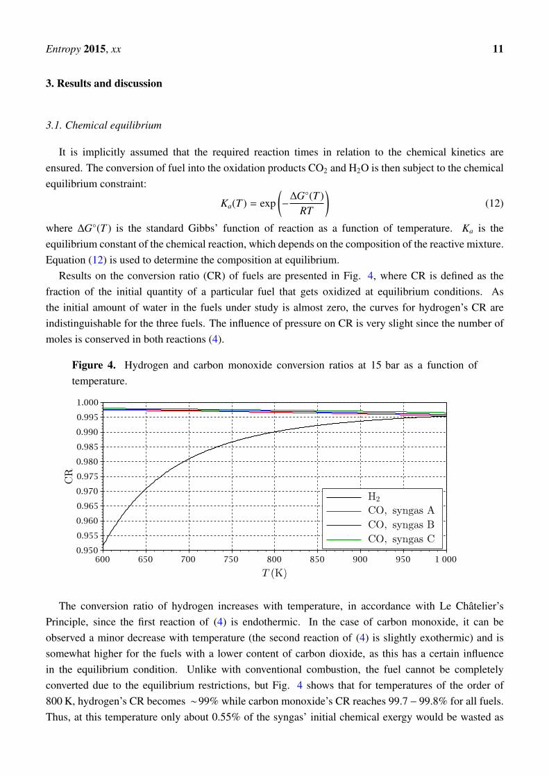
Results on the conversion ratio (CR) of fuels are presented in Fig. 4, where CR is defined as thefraction of the initial quantity of a particular fuel that gets oxidized at equilibrium conditions. Asthe initial amount of water in the fuels under study is almost zero, the curves for hydrogen’s CR areindistinguishable for the three fuels. The influence of pressure on CR is very slight since the number ofmoles is conserved in both reactions (4).
Figure 4. Hydrogen and carbon monoxide conversion ratios at 15 bar as a function oftemperature.
The conversion ratio of hydrogen increases with temperature, in accordance with Le Châtelier’sPrinciple, since the first reaction of (4) is endothermic. In the case of carbon monoxide, it can beobserved a minor decrease with temperature (the second reaction of (4) is slightly exothermic) and issomewhat higher for the fuels with a lower content of carbon dioxide, as this has a certain influencein the equilibrium condition. Unlike with conventional combustion, the fuel cannot be completelyconverted due to the equilibrium restrictions, but Fig. 4 shows that for temperatures of the order of800 K, hydrogen’s CR becomes ∼99% while carbon monoxide’s CR reaches 99.7− 99.8% for all fuels.Thus, at this temperature only about 0.55% of the syngas’ initial chemical exergy would be wasted as
Entropy 2015, xx 12
a result of incomplete oxidation. Nevertheless, the exergy savings associated with the “chemical heatpump” effect counterbalances more than enough this exergy loss, as discussed in section. 3.4.
With respect to the oxidation reactor, it has been found that the chemical equilibrium fails to occur, asit would be obtained for a very small mole fraction of oxygen, far below the amount of oxygen availablein the reactor.
3.2. Optimization of cycle parameters and exergy efficiency
The thermodynamic working conditions of the CLC cycle represented in Fig. 2 are defined by a smallset of parameters. The overall governing parameters are the main gas turbine (GT1) TIT (which also isthe temperature of the oxidation reactor) and the reactors pressure pr.
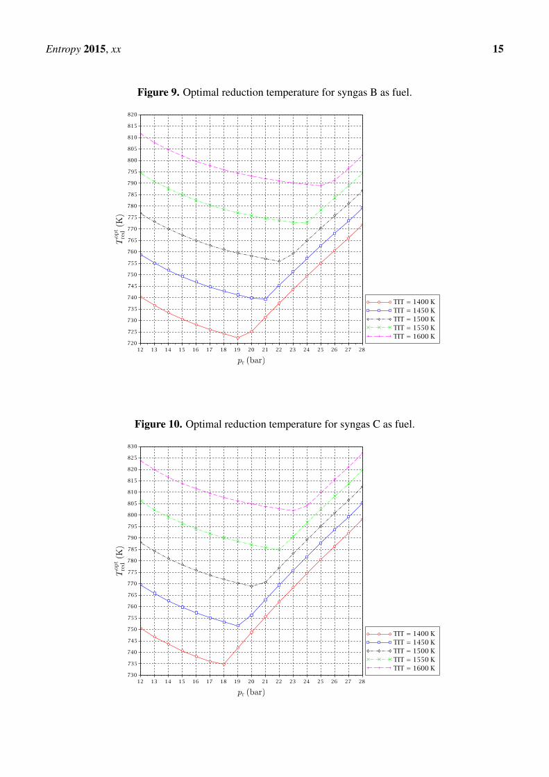
There is a degree of freedom about the reduction reactor temperature Tred. This is the key parameterto be determined by optimization, considering the opposite factors involved. As discussed previouslythe hydrogen’s CR increases with temperature. However, taking into account that the required heatto enforce this reaction is taken from the gas turbines outlet streams, it is clear that this temperature isbounded above. An iterative algorithm has been implemented to calculate Tred as the highest temperaturepossible that allows to satisfy the energy balance in the reduction reactor.
There is a second degree of freedom of low importance in relation with the expansion pressure at GT2outlet (stream 12). Calculations show that the pressure that gives the best ratio of power developed bygas turbine GT2 to power consumed by the CO2 reactors is very close to 1.5 bar for all fuels, but theinfluence in the results is minor in a quite broad range.
The cycle performance is evaluated from an exergetic point of view. The exergy efficiency is given by
ηex =WGT1 + WGT2 + WST + WCO2
Efuel(13)
WGT1 is the power generated by GT1, subtracted the air compressor power consumption, WGT2 is thepower generated by GT2 minus the fuel compressor consumption, WST is the power produced by thesteam turbine and WCO2 is the power consumption of both CO2 compressors:
WGT1 = ηem(h1 − h2 + h4 − h5) ; WGT2 = ηem(h8 − h9 + h11 − h12) ; WCO2 = (h15 − h16 + h17 − h18)
A electromechanical efficiency for gas turbine ensembles of ηem = 0.98 has been considered. WST iscalculated in a similar way.
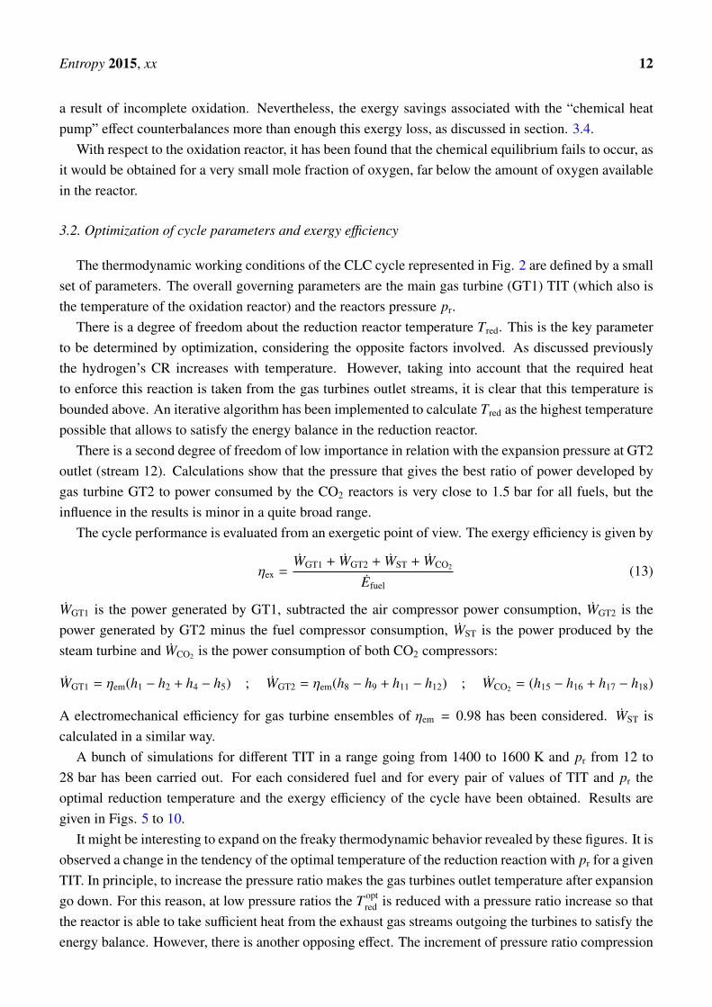
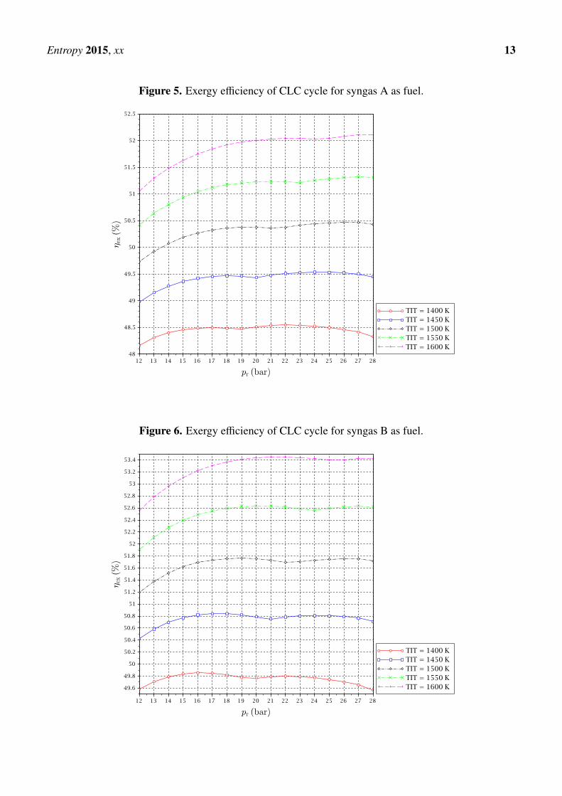
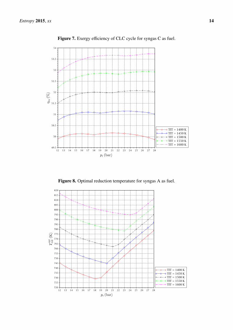
A bunch of simulations for different TIT in a range going from 1400 to 1600 K and pr from 12 to28 bar has been carried out. For each considered fuel and for every pair of values of TIT and pr theoptimal reduction temperature and the exergy efficiency of the cycle have been obtained. Results aregiven in Figs. 5 to 10.
It might be interesting to expand on the freaky thermodynamic behavior revealed by these figures. It isobserved a change in the tendency of the optimal temperature of the reduction reaction with pr for a givenTIT. In principle, to increase the pressure ratio makes the gas turbines outlet temperature after expansiongo down. For this reason, at low pressure ratios the T opt
red is reduced with a pressure ratio increase so thatthe reactor is able to take sufficient heat from the exhaust gas streams outgoing the turbines to satisfy theenergy balance. However, there is another opposing effect. The increment of pressure ratio compression
Entropy 2015, xx 13
Figure 5. Exergy efficiency of CLC cycle for syngas A as fuel.
Figure 6. Exergy efficiency of CLC cycle for syngas B as fuel.
Entropy 2015, xx 14
Figure 7. Exergy efficiency of CLC cycle for syngas C as fuel.
Figure 8. Optimal reduction temperature for syngas A as fuel.
Entropy 2015, xx 15
Figure 9. Optimal reduction temperature for syngas B as fuel.
Figure 10. Optimal reduction temperature for syngas C as fuel.
Entropy 2015, xx 16
leads to higher temperatures at the compressors outlets, what implies that the inputs to the reductionreactor are received there at higher temperatures. In summary, the following two effects occur at thesame time when the reactors pressure is increased:
a) Lower temperature of gas streams at the outlet of the gas turbines.
b) A decrease of heat demand in the reduction reactor.
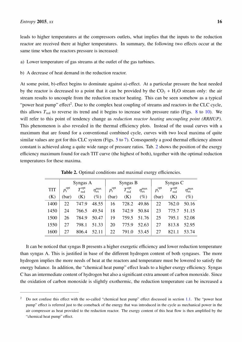
At some point, b)-effect begins to dominate against a)-effect. At a particular pressure the heat neededby the reactor is decreased to a point that it can be provided by the CO2 + H2O stream only: the airstream results to uncouple from the reduction reactor heating. This can be seen somehow as a typical“power heat pump” effect2. Due to the complex heat coupling of streams and reactors in the CLC cycle,this allows Tred to reverse its trend and it begins to increase with pressure ratio (Figs. 8 to 10). Wewill refer to this point of tendency change as reduction reactor heating uncoupling point (RRHUP).This phenomenon is also revealed in the thermal efficiency plots. Instead of the usual curves with amaximum that are found for a conventional combined cycle, curves with two local maxima of quitesimilar values are got for this CLC system (Figs. 5 to 7). Consequently a good thermal efficiency almostconstant is achieved along a quite wide range of pressure ratios. Tab. 2 shows the position of the exergyefficiency maximum found for each TIT curve (the highest of both), together with the optimal reductiontemperatures for these maxima.
Table 2. Optimal conditions and maximal exergy efficiencies.
Syngas A Syngas B Syngas CTIT popt
r T optred ηmax
ex poptr T opt
red ηmaxex popt
r T optred ηmax
ex
(K) (bar) (K) (%) (bar) (K) (%) (bar) (K) (%)1400 22 747.9 48.55 16 728.2 49.86 22 762.0 50.161450 24 766.5 49.54 18 742.9 50.84 23 775.7 51.151500 26 784.9 50.47 19 759.5 51.76 25 795.1 52.081550 27 798.1 51.33 20 775.9 52.63 27 813.8 52.951600 27 806.4 52.11 22 791.0 53.45 27 821.1 53.74
It can be noticed that syngas B presents a higher exergetic efficiency and lower reduction temperaturethan syngas A. This is justified in base of the different hydrogen content of both syngases. The morehydrogen implies the more needs of heat at the reactors and temperature must be lowered to satisfy theenergy balance. In addition, the “chemical heat pump” effect leads to a higher exergy efficiency. SyngasC has an intermediate content of hydrogen but also a significant extra amount of carbon monoxide. Sincethe oxidation of carbon monoxide is slightly exothermic, the reduction temperature can be increased a
2 Do not confuse this effect with the so-called “chemical heat pump” effect discussed in section 1.1. The “power heatpump” effect is referred just to the comeback of the energy that was introduced in the cycle as mechanical power in theair compressor as heat provided to the reduction reactor. The exergy content of this heat flow is then amplified by the“chemical heat pump” effect.
Entropy 2015, xx 17
bit and the exergy efficiency obtained is consequently the highest of the three fuels under study. Anotherinteresting point is that for the case of syngas B, the highest maximum is the left one, i.e. at lower pr,while for syngases A and C the highest maximum is the right one, i.e. at higher pr. In any case, thedifference in the exergy efficiency between syngases B and C is very slight.
3.3. Exergy balances
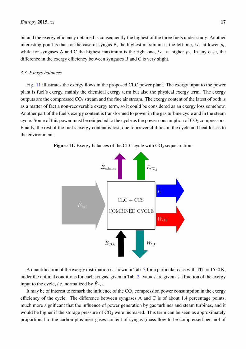
Fig. 11 illustrates the exergy flows in the proposed CLC power plant. The exergy input to the powerplant is fuel’s exergy, mainly the chemical exergy term but also the physical exergy term. The exergyoutputs are the compressed CO2 stream and the flue air stream. The exergy content of the latest of both isas a matter of fact a non-recoverable exergy term, so it could be considered as an exergy loss somehow.Another part of the fuel’s exergy content is transformed to power in the gas turbine cycle and in the steamcycle. Some of this power must be reinjected to the cycle as the power consumption of CO2 compressors.Finally, the rest of the fuel’s exergy content is lost, due to irreversibilities in the cycle and heat losses tothe environment.
Figure 11. Exergy balances of the CLC cycle with CO2 sequestration.
COMBINED CYCLE
It
WGT
WSTECO2
ECO2Eexhaust
Efuel
CLC + CCS
A quantification of the exergy distribution is shown in Tab. 3 for a particular case with TIT = 1550 K,under the optimal conditions for each syngas, given in Tab. 2. Values are given as a fraction of the exergyinput to the cycle, i.e. normalized by Efuel.
It may be of interest to remark the influence of the CO2 compression power consumption in the exergyefficiency of the cycle. The difference between syngases A and C is of about 1.4 percentage points,much more significant that the influence of power generation by gas turbines and steam turbines, and itwould be higher if the storage pressure of CO2 were increased. This term can be seen as approximatelyproportional to the carbon plus inert gases content of syngas (mass flow to be compressed per mol of
Entropy 2015, xx 18
Table 3. Exergy balances of the whole CLC cycle for TIT = 1550 K and optimal conditions.
FuelECO2 Eexhaust WGT WST WCO2 It
(%) (%) (%) (%) (%) (%)Syngas A 10.07 1.20 39.82 16.99 -5.49 37.41Syngas B 8.25 1.20 39.54 17.49 -4.40 37.92Syngas C 8.17 1.29 39.54 17.50 -4.09 37.59
fuel) and approximately inversely proportional to the fuels chemical exergy. This could be characterizedby a fuel dependent carbon&inert/exergy parameter:
C&I/Ex =xCO + xCO2 + xN2 + xAr
eCH(14)
that can be obtained from Tab. 1 for the fuels under study:
Syngas A Syngas B Syngas CC&I/Ex (mol/MJ) : 3.685 2.946 2.771
and is more or less proportional to the WCO2 values given in Tab. 3.It is also interesting to analyze the dependence of the main exergy flows with the operating conditions.
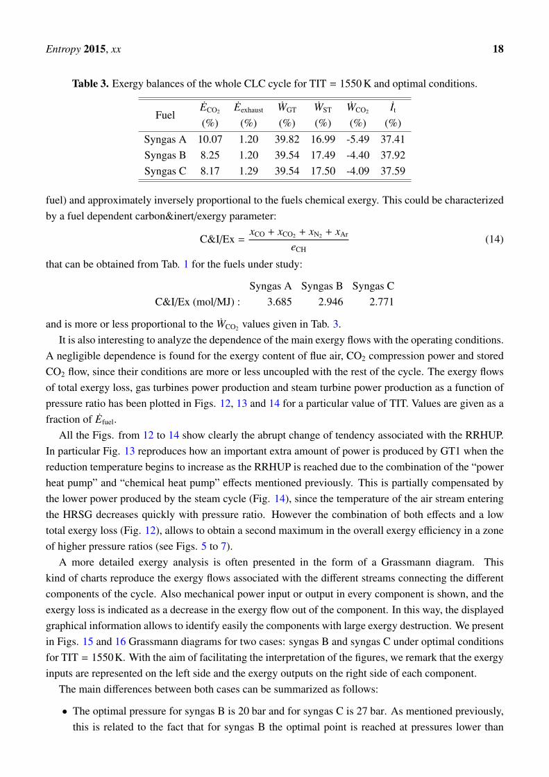
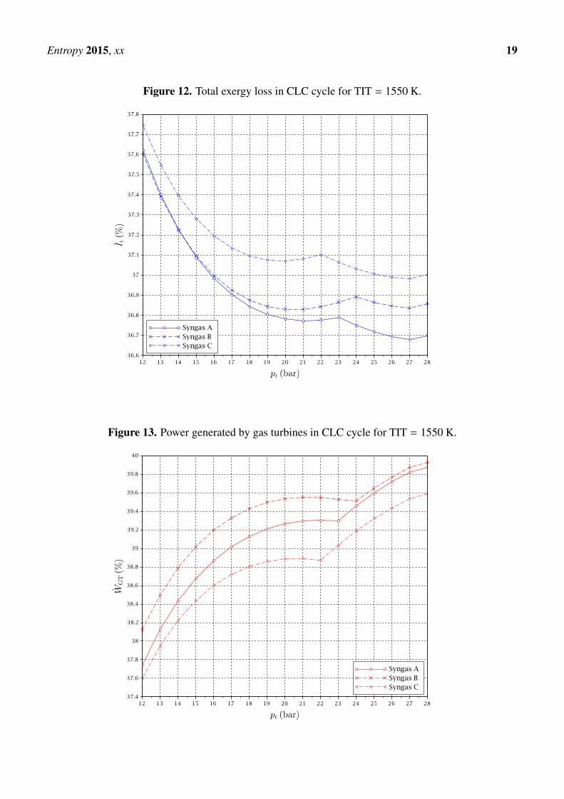
A negligible dependence is found for the exergy content of flue air, CO2 compression power and storedCO2 flow, since their conditions are more or less uncoupled with the rest of the cycle. The exergy flowsof total exergy loss, gas turbines power production and steam turbine power production as a function ofpressure ratio has been plotted in Figs. 12, 13 and 14 for a particular value of TIT. Values are given as afraction of Efuel.
All the Figs. from 12 to 14 show clearly the abrupt change of tendency associated with the RRHUP.In particular Fig. 13 reproduces how an important extra amount of power is produced by GT1 when thereduction temperature begins to increase as the RRHUP is reached due to the combination of the “powerheat pump” and “chemical heat pump” effects mentioned previously. This is partially compensated bythe lower power produced by the steam cycle (Fig. 14), since the temperature of the air stream enteringthe HRSG decreases quickly with pressure ratio. However the combination of both effects and a lowtotal exergy loss (Fig. 12), allows to obtain a second maximum in the overall exergy efficiency in a zoneof higher pressure ratios (see Figs. 5 to 7).
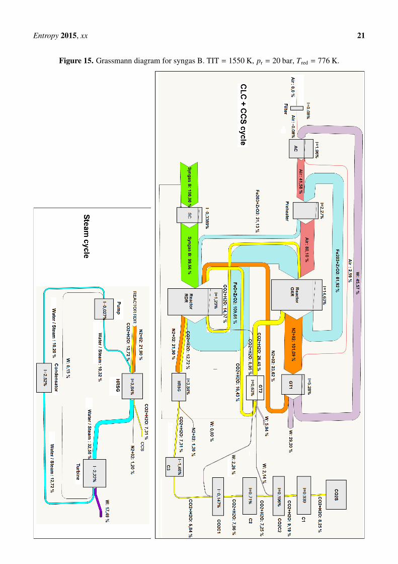
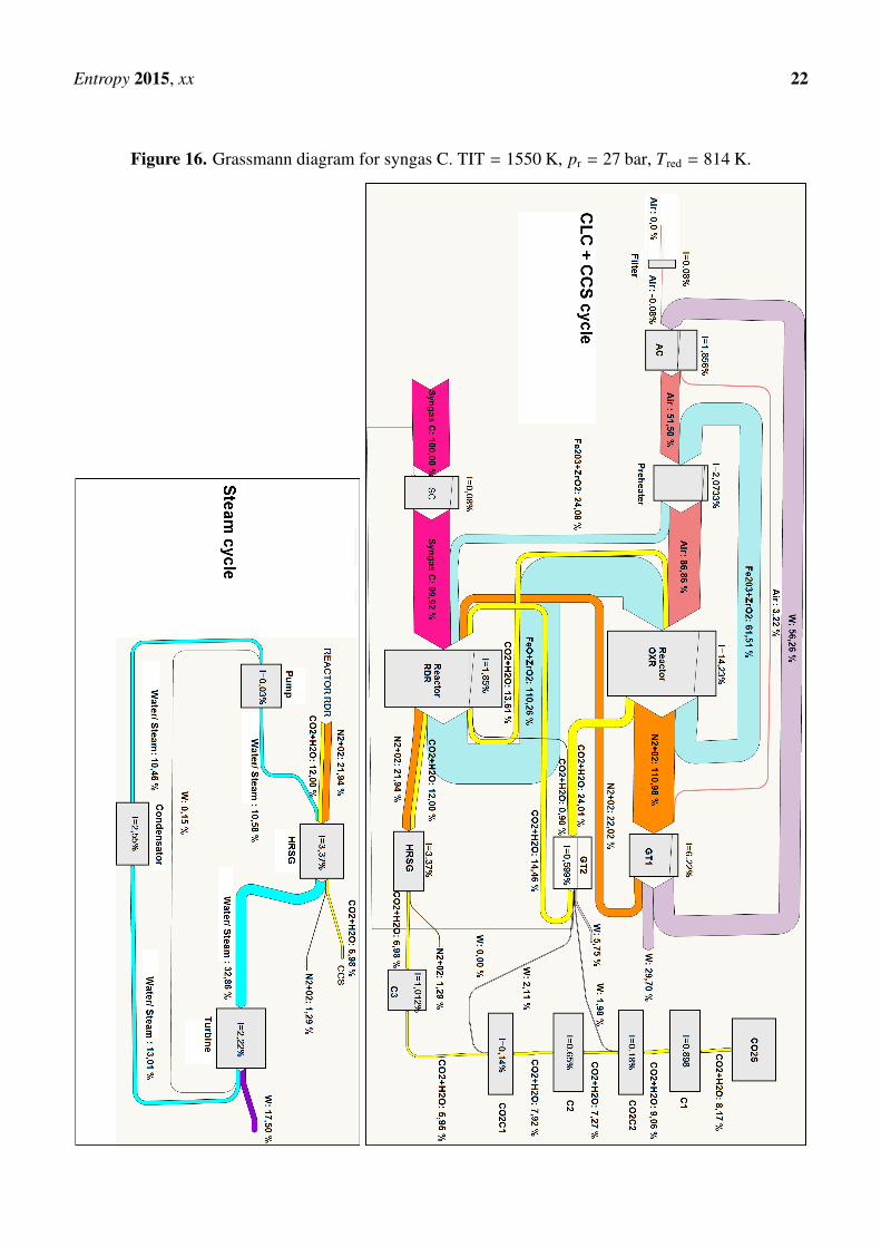
A more detailed exergy analysis is often presented in the form of a Grassmann diagram. Thiskind of charts reproduce the exergy flows associated with the different streams connecting the differentcomponents of the cycle. Also mechanical power input or output in every component is shown, and theexergy loss is indicated as a decrease in the exergy flow out of the component. In this way, the displayedgraphical information allows to identify easily the components with large exergy destruction. We presentin Figs. 15 and 16 Grassmann diagrams for two cases: syngas B and syngas C under optimal conditionsfor TIT = 1550K. With the aim of facilitating the interpretation of the figures, we remark that the exergyinputs are represented on the left side and the exergy outputs on the right side of each component.
The main differences between both cases can be summarized as follows:
• The optimal pressure for syngas B is 20 bar and for syngas C is 27 bar. As mentioned previously,this is related to the fact that for syngas B the optimal point is reached at pressures lower than
Entropy 2015, xx 19
Figure 12. Total exergy loss in CLC cycle for TIT = 1550 K.
Figure 13. Power generated by gas turbines in CLC cycle for TIT = 1550 K.
Entropy 2015, xx 20
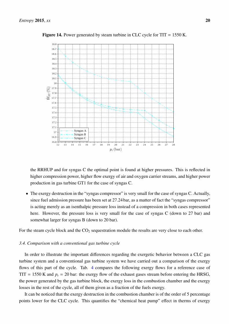
Figure 14. Power generated by steam turbine in CLC cycle for TIT = 1550 K.
the RRHUP and for syngas C the optimal point is found at higher pressures. This is reflected inhigher compression power, higher flow exergy of air and oxygen carrier streams, and higher powerproduction in gas turbine GT1 for the case of syngas C.
• The exergy destruction in the “syngas compressor” is very small for the case of syngas C. Actually,since fuel admission pressure has been set at 27.24bar, as a matter of fact the “syngas compressor”is acting merely as an isenthalpic pressure loss instead of a compression in both cases representedhere. However, the pressure loss is very small for the case of syngas C (down to 27 bar) andsomewhat larger for syngas B (down to 20 bar).
For the steam cycle block and the CO2 sequestration module the results are very close to each other.
3.4. Comparison with a conventional gas turbine cycle
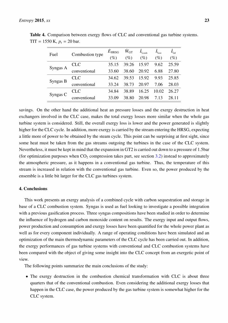
In order to illustrate the important differences regarding the exergetic behavior between a CLC gasturbine system and a conventional gas turbine system we have carried out a comparison of the exergyflows of this part of the cycle. Tab. 4 compares the following exergy flows for a reference case ofTIT = 1550 K and pr = 20 bar: the exergy flow of the exhaust gases stream before entering the HRSG,the power generated by the gas turbine block, the exergy loss in the combustion chamber and the exergylosses in the rest of the cycle, all of them given as a fraction of the fuels exergy.
It can be noticed that the exergy destruction in the combustion chamber is of the order of 5 percentagepoints lower for the CLC cycle. This quantifies the “chemical heat pump” effect in therms of exergy
Entropy 2015, xx 21
Figure 15. Grassmann diagram for syngas B. TIT = 1550 K, pr = 20 bar, Tred = 776 K.
Entropy 2015, xx 22
Figure 16. Grassmann diagram for syngas C. TIT = 1550 K, pr = 27 bar, Tred = 814 K.
Entropy 2015, xx 23
Table 4. Comparison between exergy flows of CLC and conventional gas turbine systems.TIT = 1550 K, pr = 20 bar.
Fuel Combustion typeEHRSG WGT Itcomb Itrest Itall
(%) (%) (%) (%) (%)
Syngas ACLC 35.15 39.26 15.97 9.62 25.59conventional 33.60 38.60 20.92 6.88 27.80
Syngas BCLC 34.62 39.53 15.92 9.93 25.85conventional 33.24 38.73 20.97 7.06 28.03
Syngas CCLC 34.84 38.89 16.25 10.02 26.27conventional 33.09 38.80 20.98 7.13 28.11
savings. On the other hand the additional heat an pressure losses and the exergy destruction in heatexchangers involved in the CLC case, makes the total exergy losses more similar when the whole gasturbine system is considered. Still, the overall exergy loss is lower and the power generated is slightlyhigher for the CLC cycle. In addition, more exergy is carried by the stream entering the HRSG, expectinga little more of power to be obtained by the steam cycle. This point can be surprising at first sight, sincesome heat must be taken from the gas streams outgoing the turbines in the case of the CLC system.Nevertheless, it must be kept in mind that the expansion in GT2 is carried out down to a pressure of 1.5bar(for optimization purposes when CO2 compression takes part, see section 3.2) instead to approximatelythe atmospheric pressure, as it happens in a conventional gas turbine. Thus, the temperature of thisstream is increased in relation with the conventional gas turbine. Even so, the power produced by theensemble is a little bit larger for the CLC gas turbines system.
4. Conclusions
This work presents an exergy analysis of a combined cycle with carbon sequestration and storage inbase of a CLC combustion system. Syngas is used as fuel looking to investigate a possible integrationwith a previous gasification process. Three syngas compositions have been studied in order to determinethe influence of hydrogen and carbon monoxide content on results. The exergy input and output flows,power production and consumption and exergy losses have been quantified for the whole power plant aswell as for every component individually. A range of operating conditions have been simulated and anoptimization of the main thermodynamic parameters of the CLC cycle has been carried out. In addition,the exergy performances of gas turbine systems with conventional and CLC combustion systems havebeen compared with the object of giving some insight into the CLC concept from an exergetic point ofview.
The following points summarize the main conclusions of the study:
• The exergy destruction in the combustion chemical transformation with CLC is about threequarters that of the conventional combustion. Even considering the additional exergy losses thathappen in the CLC case, the power produced by the gas turbine system is somewhat higher for theCLC system.
Entropy 2015, xx 24
• The exergy efficiency of a CLC gas turbine combined cycle including a carbon sequestration andstorage module is very notable. Figures of about 50% are reached including the important powerconsumption for CO2 compression up to the storage pressure.
• The optimal pressure ratios from an exergetic point of view is moderate and easily attainablefor modern gas turbine systems, although some differences between fuels have been found.Furthermore, a wide range of pressure ratio still gives a good performance due to the peculiarbehavior of the efficiency curves.
• Chemical equilibrium calculations confirm that the heat balance can be achieved at the reductionreactor with a high degree of fuel oxidation ratio in a temperature range of 720–820 K.
• The combination of some thermodynamic effects induces a peculiar tendency change of theoptimal reduction temperature with the operating conditions when the so-called reduction reactorheating uncoupling point is reached. This phenomenon implies an extra power production in theCLC based gas turbines in comparison with the expected tendency.
• The fuel’s composition has an important role in relation to the exergy flows that take place in theCLC cycle. The influence of fuel composition is much more important in determining the optimalcycle conditions than in case of conventional combustion, due to the complex dynamics regardingchemical equilibrium and heat flows and balances in CLC reactors.
Although at this moment we can say that we are far from the technological maturity required for anindustrial use, the results point out that CLC is a promising technique with a great potential for powergeneration with high efficiency and CO2 emissions almost nil.
Conflicts of Interest
The authors declare no conflict of interest.
References
1. Chiesa, P.; Consonni, S. Natural gas fired combined cycles with low CO2 emissions. J Eng GasTurb Power 2000, 122, 429–436.
2. Urech, J.; Tock, L.; Harkin, T.; Hoadley, A.; Maréchal, F. An assessment of different solvent-basedcapture technologies within an IGCC-CCS power plant. Energy 2014, 64, 268–276.
3. Hagi, H.; Bouallou, Y.L.M.M.N.C. Performance assessment of first generation oxy-coal powerplants through an exergy-based process integration methodology. Energy 2014, 69, 272–284.
4. Ishida, M.; Jin, H. A new advanced power-generation system using chemical-looping combustion.Energy 1994, 19, 415–422.
5. Zhang, X.; Han, W.; Hong, H.; Jin, H. A chemical intercooling gas turbine cycle withchemical-looping combustion. Energy 2009, 34, 2131–2136.
6. Anheden, M.; Svedberg, G. Exergy analysis of chemical-looping combustion systems. EnergyConv Manag 1998, 39, 1967–1980.
Entropy 2015, xx 25
7. Anheden, M. Analysis of gas turbine systems for sustainable energy conversion. PhD thesis, RoyalInstitute of Technology, ISRN KTH/KET/–11–SE, Stockholm, Sweden, 2000.
8. Jiménez, Á.; López, I.; González, C.; Nieto, R.; Rodríguez, J. Energetic analysis of a syngas-fueledchemical-looping combustion combined cycle with integration of carbon dioxide sequestration.Energy 2014, 76, 694–703.
9. Jing, D.Z.X. Chemical amplifier and energy utilization principles of heat conversion cycle systems.Energy 2013, 63, 180–188.
10. Ishida, M.; Jin, H. A novel chemical-looping combustor without NOx formation. J Ind Eng Chem1996, 35, 2469–2472.
11. Consonni, S.; Lozza, G.; Pelliccia, G.; Rossini, S.; Saviano, F. Chemical-looping combustion forcombined cycles with CO2 capture. J Eng Gas Turb Power 2006, 128, 525–534.
12. Nieto, R.; González, C.; López, I.; Jiménez, Á. Efficiency of a standard gas-turbine powergeneration cycle running on different fuels. Int J Exergy 2011, 9, 112–126.
13. Mínguez, M.; Jiménez, Á.; Rodríguez, J.; González, C.; López, I.; Nieto, R. Analysis of energeticand exergetic efficiency, and environmental benefits of biomass integrated gasification combinedcycle technology. Waste Manage Res 2013, 31, 401–412.
14. Kotas, T.J. The exergy method of thermal plant analysis; Butterworths: London, UK, 1985.15. Escudero, M.; Jiménez, Á.; González, C.; Nieto, R.; López, I. Analysis of the behavior of
biofuel-fired gas turbine power plants. Therm Sci 2012, 16, 849–864.16. http://webbook.nist.gov/chemistry/form-ser.html. online (last access on 30/07/2014), National
Institute of Standards and Technology, U.S. Department of Commerce.17. Daubert, T.E.; Danner, R.P. Physical and thermodynamic properties of pure chemicals: Data
compilation; Hemisphere Publishing Corporation: New York, NY, USA, 1989.
c© 2015 by the authors; licensee MDPI, Basel, Switzerland. This article is an open access articledistributed under the terms and conditions of the Creative Commons Attribution license(http://creativecommons.org/licenses/by/3.0/).