
Exergetic, Economic and Environmental (3E) Analyses, And Multiobjective
9
Exergetic, economic and environmental (3E) analyses, and multi- objective optimization of a CO 2 /NH 3 cascade refrigeration system Mehdi Aminyavari a , Behzad Najafi b , Ali Shirazi c, * , Fabio Rinaldi b a Scuola di Ingegneria Industriale, Campus di Piacenza, Politecnico di Milano, Via Scalabrini, 76, 29100 Piacenza, Italy b Dipartimento di Energia, Politecnico di Milano, Via Lambruschini 4, 20156 Milano, Italy c School of Mechanical and Manufacturing Engineering, The University of New South Wales (UNSW), Kensington, New South Wales 2052, Australia highlights Exergetic-economic-environmental analysis was applied on CO 2 /NH 3 refrigeration system. Exergetic efficiency and total cost rate were considered as the conflicting objectives. Total cost rate included capital, maintenance, operational and CO 2 emission costs. Multi-objective optimization was applied to obtain a set of optimal solutions. The effect of variations in electricity unit cost on Pareto front was investigated. article info Article history: Received 3 July 2013 Accepted 29 December 2013 Available online 6 January 2014 Keywords: Cascade refrigeration system CO 2 Ammonia Exergy Economic Multi-objective optimization abstract In the present study, a CO 2 /NH 3 cascade refrigeration system is modeled and analyzed from exergetic, economic and environmental points of view. In the next step, multi-objective optimization using genetic algorithm method is employed to achieve the optimal design parameters of the system. The exergetic efficiency and the total cost rate of the system (including the capital and maintenance costs, operational cost, and social cost of CO 2 emission) are taken into account as objective functions. A set of optimal solutions is achieved and a final optimum point is then chosen using TOPSIS decision-making method. A sensitivity analysis has been performed to study the effect of variation of the unit cost of electricity on the achieved optimal solutions. While operating at the achieved optimum design, the variation of the exergy destruction of each component and the whole system due to the change in the cooling load has also been investigated. The optimization results demonstrate that for the considered plant with cooling capacity of 50 kW, the optimum design selected from the Pareto front results in exergetic efficiency of 45.89%, while it leads to the total cost rate of 0.01099 US$ s 1 . Ó 2014 Elsevier Ltd. All rights reserved. 1. Introduction In consequence of environmental issues related to the global warming and ozone layer depletion attributed to the application of synthetic refrigerants (CFC’s, HCFC’s and HFC’s), the return to the utilization of natural materials for refrigeration purposes appears to be an appropriate alternative. Accordingly, the natural refrigerants such as ammonia, carbon dioxide and hydrocarbons, have recently received increasing attentions [1]. In refrigeration systems involving a high temperature difference between the heat source and the heat sink, employing a single stage refrigeration system is not economical owing to the fact that the corresponding high pressure ratio leads to a low volumetric efficiency of the compressors and consequently low coefficient of performance of the system. In addition, utilizing a refrigerant in a wide temperature range results in a decrement in evaporator pressure and an increment in suction volume and condenser pressure [2]. Employing cascade refrigeration systems is an appropriate solution to evade aforementioned issues. CO 2 /NH 3 cascade system is a well-known system in refrigeration industry in which two natural refrigerants are used. Ammonia, despite its apparent disadvantages of toxicity and moderate flammability [3], is a natural refrigerant which has been most commonly adopted in the high temperature cycle of two-stage refrigeration systems. Owing to the fact that at low temperatures (under 35 C), it has a * Corresponding author. Tel.: þ61 413077896. E-mail addresses: [email protected] (M. Aminyavari), behzad. najafi@mail.polimi.it (B. Najafi), [email protected] (A. Shirazi), fabio. [email protected] (F. Rinaldi). Contents lists available at ScienceDirect Applied Thermal Engineering journal homepage: www.elsevier.com/locate/apthermeng 1359-4311/$ e see front matter Ó 2014 Elsevier Ltd. All rights reserved. http://dx.doi.org/10.1016/j.applthermaleng.2013.12.075 Applied Thermal Engineering 65 (2014) 42e50
-
Upload
henrique-neiva-guimaraes -
Category
Documents
-
view
219 -
download
1
description
In the present study, a CO2/NH3 cascade refrigeration system is modeled and analyzed from exergetic,economic and environmental points of view. In the next step, multi-objective optimization using geneticalgorithm method is employed to achieve the optimal design parameters of the system. The exergeticefficiency and the total cost rate of the system (including the capital and maintenance costs, operationalcost, and social cost of CO2 emission) are taken into account as objective functions. A set of optimalsolutions is achieved and a final optimum point is then chosen using TOPSIS decision-making method.A sensitivity analysis has been performed to study the effect of variation of the unit cost of electricity onthe achieved optimal solutions. While operating at the achieved optimum design, the variation of theexergy destruction of each component and the whole system due to the change in the cooling load hasalso been investigated. The optimization results demonstrate that for the considered plant with coolingcapacity of 50 kW, the optimum design selected from the Pareto front results in exergetic efficiency of45.89%, while it leads to the total cost rate of 0.01099 US$ s1.
Transcript of Exergetic, Economic and Environmental (3E) Analyses, And Multiobjective

lable at ScienceDirect
Applied Thermal Engineering 65 (2014) 42e50
Contents lists avai
Applied Thermal Engineering
journal homepage: www.elsevier .com/locate/apthermeng
Exergetic, economic and environmental (3E) analyses, and multi-objective optimization of a CO2/NH3 cascade refrigeration system
Mehdi Aminyavari a, Behzad Najafi b, Ali Shirazi c,*, Fabio Rinaldi b
a Scuola di Ingegneria Industriale, Campus di Piacenza, Politecnico di Milano, Via Scalabrini, 76, 29100 Piacenza, ItalybDipartimento di Energia, Politecnico di Milano, Via Lambruschini 4, 20156 Milano, Italyc School of Mechanical and Manufacturing Engineering, The University of New South Wales (UNSW), Kensington, New South Wales 2052, Australia
h i g h l i g h t s
� Exergetic-economic-environmental analysis was applied on CO2/NH3 refrigeration system.� Exergetic efficiency and total cost rate were considered as the conflicting objectives.� Total cost rate included capital, maintenance, operational and CO2 emission costs.� Multi-objective optimization was applied to obtain a set of optimal solutions.� The effect of variations in electricity unit cost on Pareto front was investigated.
a r t i c l e i n f o
Article history:Received 3 July 2013Accepted 29 December 2013Available online 6 January 2014
Keywords:Cascade refrigeration systemCO2
AmmoniaExergyEconomicMulti-objective optimization
* Corresponding author. Tel.: þ61 413077896.E-mail addresses: [email protected]
[email protected] (B. Najafi), [email protected]@polimi.it (F. Rinaldi).
1359-4311/$ e see front matter � 2014 Elsevier Ltd.http://dx.doi.org/10.1016/j.applthermaleng.2013.12.07
a b s t r a c t
In the present study, a CO2/NH3 cascade refrigeration system is modeled and analyzed from exergetic,economic and environmental points of view. In the next step, multi-objective optimization using geneticalgorithm method is employed to achieve the optimal design parameters of the system. The exergeticefficiency and the total cost rate of the system (including the capital and maintenance costs, operationalcost, and social cost of CO2 emission) are taken into account as objective functions. A set of optimalsolutions is achieved and a final optimum point is then chosen using TOPSIS decision-making method.A sensitivity analysis has been performed to study the effect of variation of the unit cost of electricity onthe achieved optimal solutions. While operating at the achieved optimum design, the variation of theexergy destruction of each component and the whole system due to the change in the cooling load hasalso been investigated. The optimization results demonstrate that for the considered plant with coolingcapacity of 50 kW, the optimum design selected from the Pareto front results in exergetic efficiency of45.89%, while it leads to the total cost rate of 0.01099 US$ s�1.
� 2014 Elsevier Ltd. All rights reserved.
1. Introduction
In consequence of environmental issues related to the globalwarming and ozone layer depletion attributed to the application ofsynthetic refrigerants (CFC’s, HCFC’s and HFC’s), the return to theutilization of natural materials for refrigeration purposes appears tobe an appropriate alternative. Accordingly, the natural refrigerantssuch as ammonia, carbon dioxide and hydrocarbons, have recentlyreceived increasing attentions [1].
.it (M. Aminyavari), behzad.sw.edu.au (A. Shirazi), fabio.
All rights reserved.5
In refrigeration systems involving a high temperature differencebetween the heat source and the heat sink, employing a singlestage refrigeration system is not economical owing to the fact thatthe corresponding high pressure ratio leads to a low volumetricefficiency of the compressors and consequently low coefficient ofperformance of the system. In addition, utilizing a refrigerant in awide temperature range results in a decrement in evaporatorpressure and an increment in suction volume and condenserpressure [2]. Employing cascade refrigeration systems is anappropriate solution to evade aforementioned issues. CO2/NH3cascade system is a well-known system in refrigeration industry inwhich two natural refrigerants are used. Ammonia, despite itsapparent disadvantages of toxicity and moderate flammability [3],is a natural refrigerant which has been most commonly adopted inthe high temperature cycle of two-stage refrigeration systems.Owing to the fact that at low temperatures (under �35 �C), it has a

Nomenclature
A area (m2)_C cost rate (US$ s�1)CCO2
unit damage cost of carbon dioxide emissions (US$ Kg�1 CO2)
Celec electricity unit cost (US$ (kW h)�1)Cp specific heat at constant pressure (kJ kg�1 K�1)CFC chlorofluorocarbonCRF capital recovery factorE energy (kJ)_E exergy flow rate (kW)e specific exergy (kJ kmol�1)h specific enthalpy (kJ kg�1)i interest rateHCFC hydrochlorofluorocarbonHFC hydrofluorocarbonHTC high temperature circuitk specific heat ratioLTC low temperature circuit_m mass flow rate (kg s�1)N operational hours in a yearn system lifetime (year)_n molar flow rate (kmol s�1)p pressure (kPa)_Q the time rate of heat transfer (kW)rP pressure ratioR universal gas constant (kJ kmol�1 K�1)s specific entropy (kJ kg�1 K�1)T temperature (K or �C)TOPSIS Technique for Order Preference by Similarity to an
Ideal Solution_W mechanical work (kW)X molar fractionZ capital cost (US$)_Z capital cost rate (US$ s�1)
Greek symbolsh efficiencym emission conversion factor of electricity from grid
(kg (kW h)�1)F maintenance factorD difference
Subscripts0 ambient, referenceC condenserCAS cascade condenserCL cold spacecomp compressorcond condenserCV control volumeD destructione exitelec electricalenv environmentalevap evaporatorexp expansion valveH high temperaturei inletL low temperaturem mechanicalMC cascade condenser (middle)ME cascade evaporator (middle)op operationp pressures isentropic
SuperscriptCH chemicalPH physicalQ heat transferW work
M. Aminyavari et al. / Applied Thermal Engineering 65 (2014) 42e50 43
vapor pressure lower than atmospheric pressure, which may causeair leakage into the system, ammonia cannot be used in the lowtemperature circuit. In contrast, carbon dioxide is a non-toxic, non-flammable gas with a positive vapor pressure at temperaturesbelow�35 �C which makes it a suitable choice for low temperaturecascade cycle [3]. Therefore, ammonia and carbon dioxide havebeen shown to be the most promising natural refrigerants across abroad spectrum of commercial and industrial refrigeration and air-conditioning systems [4].
Experimental studies have been carried out on performance ofCO2/NH3 cascade systems and the effect of operating parameterssuch as the evaporation and condensation temperatures of the lowtemperature circuit (LTC) on the performance of the system wereinvestigated [1,5]. Some studies have been conducted on thetheoretical analysis of cascade refrigeration system based on thefirst law of thermodynamic [1,6]. A similar study was also carriedout by Messineo [7] in which a comparison between the CO2/NH3cascade refrigeration system and a hydrofluorocarbon (HFC) two-stage system was performed. Lee et al. [3] presented anenergetic-exegetic analysis of CO2/NH3 cascade system in order tomaximize the COP and minimize the exergy destruction of thesystem.
Economic considerations should also be taken into accountwhile analyzing a refrigeration plant. Thermo-economic method isa proper approach for analyzing the systems from both
thermodynamic and economic points of view [8]. Mitishita et al. [9]performed a thermo-economic design and optimization of frost-free refrigerators. Rezayan and Behbahaninia [2] carried out asimilar study on CO2/NH3 system.
Multi-objective optimizationmethod is an efficient approach foroptimizing the problems dealing with conflicting objectives, theapproach which has been successfully utilized for optimization ofheat exchangers [10e14]. Gebreslassie et al. [15] performed multi-objective optimization on sustainable single-effect water/lithiumbromide absorption cycle. Sanaye and Shirazi [16] applied themultiobjective optimization on an ice thermal energy storage (ITES)system .Navidbakhsh and Shirazi [17] also applied a similar opti-mization method on a PCM incorporated ITES system for air con-ditioning applications.
In the present paper, thermodynamic (energetic and exergetic),economic, and environmental analyses as well as multi-objectiveoptimization of a CO2/NH3 cascade refrigeration system are car-ried out. The refrigeration system is modeled and validated basedon the results of a previous study. Afterward, considering theexergetic efficiency (to be maximized) and the total cost rate of thesystem (to be minimized) as objective functions, multi-objectiveoptimization of the system is performed. The capital and mainte-nance costs of system components, the operational cost, and thesocial cost due to CO2 emission are included in the total cost rate ofthe plant. Applying the mentioned optimization approach, a set of

0-10-20-30
-40-50-60-70
10203040
5060708090100110
120130140150160170
180190200
0 1 2 3 4 5 6 7
s (kJ kg-1 K-1)s (kJ kg-1 K-1)
T (˚C)T (˚C)
TC
TME
TE
TMC
NH3
CO2
14
6
7
83
2
5
Fig. 2. T-S diagram of the CO2/NH3 refrigeration cycle.
M. Aminyavari et al. / Applied Thermal Engineering 65 (2014) 42e5044
optimal solutions, called Pareto front, is achieved. In the next step,Euclidean method is employed for non-dimensionalization of thePareto front results and the TOPSIS method is utilized to choose afinal optimum design point. A sensitivity analysis has been per-formed in order to study the effect of variation of unit cost ofelectricity on the Pareto front. The effect of the variation of thecooling load on the exergy destruction within the systems is alsoinvestigated.
2. Mathematical modeling
2.1. Description of cascade refrigeration cycle
A schematic layout of the CO2/NH3 refrigeration cycle which hasbeen considered in the present study is demonstrated in Fig. 1. Thesystem consists of two separate circuits including a high temper-ature circuit (HTC) and a low temperature one (LTC). Ammonia isused as the refrigerant in the high temperature circuit while in thelow temperature circuit carbon dioxide is employed as the refrig-erant. Each refrigeration system consists of a compressor, acondenser, an expansion valve, and an evaporator. The two circuitsare thermally coupled to each other through a cascade condenser,which acts as an evaporator for the HTC and a condenser for theLTC.
The evaporator of LTC absorbs the cooling load _QL from thecooling space in the evaporating temperature TE. The condenser inHTC rejects heat flow of _QH at condensing temperature of TC to theambient which has the temperature of T0. The heat transferredfrom the condenser of LTC to the evaporator of HTC in the cascadecondenser is equal to the sum of the absorbed heat by the evapo-rator of the LTC and thework input to the LTC compressor. Similarly,the heat rejected from the HTC condenser is equal to the sum of theheat absorbed by the evaporator of HTC and the work input to theHTC compressor. The cascade condenser temperature difference,DTCAS is the difference between the evaporation temperature ofammonia and the condensation temperature of carbon dioxide,which are called TME and TMC respectively. The TeS diagram of thecycle is also illustrated in Fig. 2.
HTC
LTC
Cold space, TCL
Ambient, T0
QH
QM
Condenser
Cascade condenser
Evaporator
Compressor
CompressorExpantionvalve
Expantionvalve
Wcomp,HTC
Wcomp,LTC
Wfan,HTC
Wfan,LTC
QL
TE
TC
TMC
TME
1
23
4
5
67
8
Fig. 1. Schematic diagram of the CO2/NH3 refrigeration cycle.
2.2. Energetic analysis
The thermodynamic analysis of the cascade refrigeration systemwas performed based on the following general assumptions:
� Pressure and heat losses/gains in the pipe networks or systemcomponents are negligible.
� The changes in kinetic and potential energy are negligible.� All system components operate under steady-state conditions.� Gas leakage is negligible in all the joints connecting the pipes toeach component.
The thermodynamic properties of CO2 and NH3 were deter-mined using REFPROP [18]. It should also be pointed out that sincethe model is developed in MATLAB� environment, a specificMATLAB� function is employed which calls the REFPROP data baseto obtain the thermodynamic data. The governing equations basedon the energy balances for system components are obtained asfollows:
The cooling load of the system absorbed by the LTC evaporatorfrom the cold space should be equal to the enthalpy difference ofCO2 across the evaporator multiplied by its mass flow rate:
_QL ¼ _mLðh1 � h4Þ (1)
The isentropic efficiency of the LTC compressor (hs) is consid-ered as follows [1]:
hS ¼ 1� ð0:04� rPÞ (2)
The mechanical and electrical efficiencies of the compressor (hmand he) are considered to be 0.93 [2].
Applying the energy balance on the system, the compressorpower consumption ð _WLTC;compÞ is obtained as:
_WLTC;comp ¼ _mLðh2S � h1Þhshmhe
¼ _mLðh2 � h1Þhmhe
(3)

M. Aminyavari et al. / Applied Thermal Engineering 65 (2014) 42e50 45
Following the same approach used for the LTC compressor,_WHTC;comp can be calculated as follows:
_WHTC;comp ¼ _mHðh6S � h5Þhshmhe
¼ _mHðh6 � h5Þhmhe
(4)
hmhe for the HTC compressor are similarly considered to be 0.93 andthe isentropic efficiency hs is also similarly calculated using Eq. (2)
As it has been previously mentioned, both of the expansionvalves in LTC and HTC are assumed to be isenthalpic, so:
h3 ¼ h4 (5)
and
h7 ¼ h8 (6)
The heat rate exchanged from LTC to HTC in the cascadecondenser is called _QM and can be calculated as:
_QM ¼ _mHðh5 � h8Þ ¼ _mLðh2 � h3Þ (7)
The energy balance equation for HTC condenser can beexpressed by:
_QH ¼ _mHðh6 � h7Þ (8)
Writing the first law of thermodynamics for thewhole system asa control volume results in:
_QH ¼ _QL þ _WLTC;comp þ _WHTC;comp (9)
2.3. Exergetic analysis
Exergy is defined as the maximum obtainable work that a sys-tem can yield in a given state when it comes to the environmentconditions. The method of exergetic analysis is based on the secondlaw of thermodynamics and enables the designers to identifylocation, cause and true magnitude of wastes and losses in thermalsystems [19].
Applying the first and second laws of thermodynamics, thesteady state form of exergy balance equation for a control volumecan be expressed as follows:
dECVdt
¼Xj
_EQj � _E
W þXi
_Ei �Xe
_Ee � _ED ¼ 0 (10)
Where _Ei and _Ee are the exergy transfer rate at control volume in-lets and outlets, _ED is the exergy destruction rate due to irrevers-ibilities, _E
Wis the rate of exergy transfer by work, and _E
Qis the rate
of exergy transfer by heat transfer, respectively.In absence of electromagnetic, electric, nuclear, and surface
tension effects and assuming negligible values of change inpotential and kinetic energy, the exergy flow rate of the systemis divided into two parts of physical and chemical exergy [19,20]:
_E ¼ _EPH þ _E
CH(11)
The physical exergy can be determined by:
_EPH ¼ _m½ðh� h0Þ � T0ðs� s0Þ� (12)
Writing the exergy balance equation (Eq. (10)) for each systemcomponent, the exergy destruction rate of each component is ob-tained as:
_ED;evapþfan ¼�1� T0
TCL
�_QL þ
�_E4 � _E1
�þ _W fan;evap (13)
_ED;LTC;comp ¼�_E1 � _E2
�þ _WLTC;comp (14)
_ED;LTC;exp ¼�_E3 � _E4
�(15)
_ED;cas ¼�_E2 þ _E8
���_E3 þ _E5
�(16)
_ED;HTC;comp ¼�_E5 � _E6
�þ _WHTC;comp (17)
_ED;HTC;exp ¼�_E7 � _E8
�(18)
_ED;condþfan ¼ T0T0
� 1� �
_QH þ _E6 � _E7� �
þ _W fan;cond (19)
It should be noted that the power consumption of fan of theevaporator and that of the condenser, as a parasitic load, has beenadded to the exergy destruction of these components.
The total inlet exergy into the system can be found as:
_Ein ¼ _WHTC;comp þ _WLTC;comp þ _W fan;cond þ _W fan;evap (20)
The outlet exergy of the system can also be determined as:
_Eout ¼ _QL
�T0TCL
� 1�
(21)
Hence, the total exergy destruction can be calculated as:
_ED;totall ¼ _Ein � _Eout ¼Xk
_ED;k (22)
wherePk
_ED;k stands for the sum of the exergy destructions ofsystem components.
Finally, the exergetic efficiency of the system can be determinedby:
hII ¼_Eout_Ein
¼ 1�_ED;totall_Ein
(23)
M. Aminyavari et al. / Applied Thermal Engineering 65 (2014) 42e5046
2.4. Economic analysis
In this paper, the capital and maintenance costs of componentstogether with the operational cost of the plant have been taken intoaccount. In order to consider the effect of emissions, the social costof the CO2 emissions have also been included. Accordingly, the totalcost rate of the cascade system ð _CtotÞ including the capital andmaintenance costs ðP
k
_ZkÞ; operational cost ð _CopÞ; and the penaltycost due to CO2 emission ð _CenvÞ can be expressed as follows:
_Ctot ¼Xk
_Zk þ _Cop þ _Cenv (24)
2.4.1. Investment and maintenance costsThe capital cost of each component (Zk) is estimated based on
the cost functions which are listed below [2]:
ZHTC;comp ¼ 9624:2 _W0:46HTC;comp (25)
ZLTC;comp ¼ 10167:5 _W0:46LTC;comp (26)
Zcond ¼ 1397A0:89o;cond þ 629:05 _W
0:76fan;cond (27)
Zevap ¼ 1397A0:89o;evap þ 629:05 _W
0:76fan;evap (28)
Zcas:cond ¼ 2382:9A0:68o;cas:cond (29)
In engineering economics, the unit of time interval consideredfor evaluation of the capital cost is usually taken as a year and thecorresponding cost is obtained using the capital recovery factor(CRF), which can be determined by [20]:
CRF ¼ ið1þ iÞnð1þ iÞn � 1
(30)
where the terms i and n stand for the interest rate and the systemlifetime, respectively.
Moreover, to convert the capital cost (in terms of US dollar) intothe cost per unit of time _Zk; one may write:
_Zk ¼ Zk � CRF� F
N � 3600(31)
where N and F are the annual operational hours of the system andthe maintenance factor, respectively. Applying Eq. (31) for eachsystem component, the investment and maintenance cost rate ofthe whole system ðP
k
_ZkÞ is:Xk
_Zk ¼ _ZHTC;comp þ _ZLTC;comp þ _Zcond þ _Zevap þ _Zcas:cond (32)
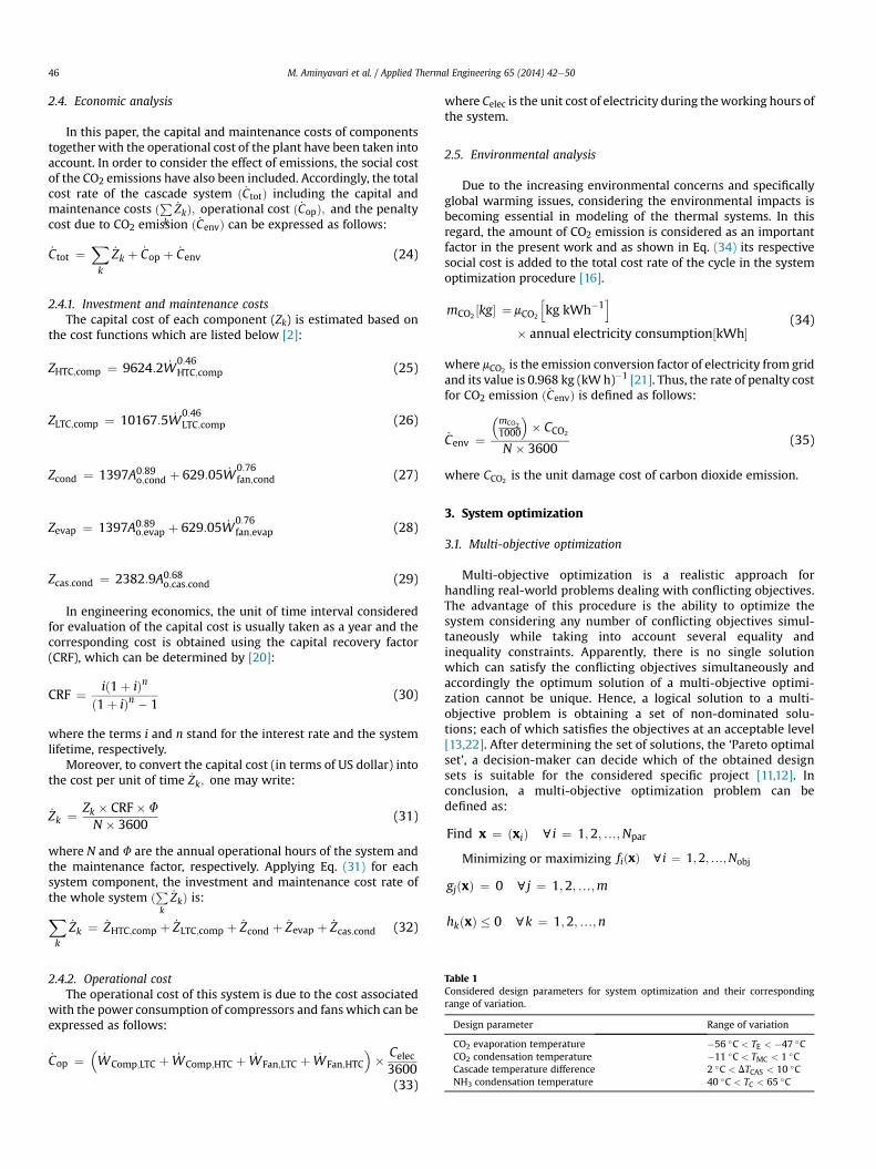
Table 1Considered design parameters for system optimization and their correspondingrange of variation.
Design parameter Range of variation
CO2 evaporation temperature �56 �C < TE < �47 �CCO2 condensation temperature �11 �C < TMC < 1 �CCascade temperature difference 2 �C < DTCAS < 10 �CNH3 condensation temperature 40 �C < TC < 65 �C
2.4.2. Operational costThe operational cost of this system is due to the cost associated
with the power consumption of compressors and fans which can beexpressed as follows:
_Cop ¼�_WComp;LTC þ _WComp;HTC þ _WFan;LTC þ _WFan;HTC
�� Celec3600(33)
where Celec is the unit cost of electricity during theworking hours ofthe system.
2.5. Environmental analysis
Due to the increasing environmental concerns and specificallyglobal warming issues, considering the environmental impacts isbecoming essential in modeling of the thermal systems. In thisregard, the amount of CO2 emission is considered as an importantfactor in the present work and as shown in Eq. (34) its respectivesocial cost is added to the total cost rate of the cycle in the systemoptimization procedure [16].
mCO2½kg� ¼mCO2
hkg kWh�1
i
� annual electricity consumption½kWh�(34)
where mCO2is the emission conversion factor of electricity from grid
and its value is 0.968 kg (kWh)�1 [21]. Thus, the rate of penalty costfor CO2 emission ð _CenvÞ is defined as follows:
_Cenv ¼�mCO21000
�� CCO2
N � 3600(35)
where CCO2is the unit damage cost of carbon dioxide emission.
3. System optimization
3.1. Multi-objective optimization
Multi-objective optimization is a realistic approach forhandling real-world problems dealing with conflicting objectives.The advantage of this procedure is the ability to optimize thesystem considering any number of conflicting objectives simul-taneously while taking into account several equality andinequality constraints. Apparently, there is no single solutionwhich can satisfy the conflicting objectives simultaneously andaccordingly the optimum solution of a multi-objective optimi-zation cannot be unique. Hence, a logical solution to a multi-objective problem is obtaining a set of non-dominated solu-tions; each of which satisfies the objectives at an acceptable level[13,22]. After determining the set of solutions, the ‘Pareto optimalset’, a decision-maker can decide which of the obtained designsets is suitable for the considered specific project [11,12]. Inconclusion, a multi-objective optimization problem can bedefined as:
Find x ¼ ðxiÞ ci ¼ 1;2;.;Npar
Minimizing or maximizing fiðxÞ ci ¼ 1;2;.;Nobj
gjðxÞ ¼ 0 cj ¼ 1;2;.;m
hkðxÞ � 0 ck ¼ 1;2;.;n

Table 2Input parameters used for simulation of cascade refrigeration system.
Parameter Value
Cooling capacity ð _QLÞ 50 kWAmbient temperature (T0) 25 �CAmbient pressure (P0) 1 atmCold refrigerated space temperature (TCL) �45 �C
M. Aminyavari et al. / Applied Thermal Engineering 65 (2014) 42e50 47
where x, Npar, fi(x), Nobj, gj(x) and hk(x) are decision variables vec-tors, number of decision variables, objectives, number of objectives,equality and inequality constraints respectively [22].
In this paper, the considered objective functions are the exer-getic efficiency (objective functions I, Eq. (23)) and total cost rate(objective function II, Eq. (24)) of the whole cascade system whichshould be maximized and minimized respectively. The list of thedesign parameters (decision variables) which has been chosen foroptimization of the system has been listed in Table 1.
3.2. Genetic algorithm
The genetic algorithm (GA) method is a heuristic techniqueinspired by the Darwin’s laws of natural selection [23]. In this al-gorithm, a solution vector (design parameters vector) is called achromosome and is made of discrete units called genes whichdetermine its features. GAs are promising techniques for solvingthe multi-objective optimization problems [23]. New generationsof solutions are produced from the previous ones employing twooperators; crossover and mutation. In the crossover operation, twochromosomes (parents) are combined together to form new chro-mosomes (offsprings). Considering the fact that individuals withhigher fitness have more chance for being chosen and generatingoffsprings, the new population will attain better genes, the factwhich results in convergence to an overall good solution. In themutation operator, random changes into the properties of chro-mosomes are applied. Considering the fact that these changes arenot significant and depend on the length of the chromosomes, thenew chromosomes produced by mutationwill not be very differentfrom the original ones. Mutation operator helps the populationsearch to escape from local optima by introducing diversity into thepopulation [23]. The flowchart in Fig. 3 represents various stages ofGAs optimization process.
As the search evolves, the population converges, and eventuallyis dominated by a set of solutions called the Pareto optimal set.After determining the Pareto optimal set, a decision-maker mustdecide which of the achieved design vectors is suitable for thespecific project. In the present work, the multi-objective GA in
Start
Generate random initialpopulation
Evaluate the fitness ofeach chromosome
Select two parentchromosomes
Use crossover operator toproduce offspring
Evaluate the fitness ofproduced offspring
Crossoverfinished?
No
Select one offspring
Use mutation operator toproduce mutated
offspring
Evaluate the fitness ofmutated offspring
Mutationfinished?
NoUse replacement operator toincorporate new chromosome
into population
Yes
Terminate?
End
Yes
No
Yes
Fig. 3. Flowchart of genetic algorithm technique for system optimization.
MATLAB� optimization toolbox has been implemented to optimizethe objective functions presented in Eqs. (23) and (24).
4. Case study
The mentioned modeling and optimization techniques areapplied for optimal design of a cascade refrigeration system to beinstalled in Shahsavar, a city in north of Iran. The cooling capacity ofthe system is 50 kW. The main input parameters used for simula-tion of the system are listed in Table 2.
The unit cost of electricity (Celec) is considered to be 0.06US$ (kW h)�1 [22]. Furthermore, the unit damage cost of carbondioxide emission ðCCO2
Þ is considered to be 90 US dollars per ton ofcarbon dioxide emissions [24].
To determine the CRF (Eq. (30)), the approximate lifetime of thesystem (n), the maintenance factor (F), and the annual interest rate(i) are considered as 15 years, 1.06, and 14% [25] respectively. Theannual operational hours of the cogeneration system (N) isconsidered to be 7000 h.
5. Results and discussion
5.1. Model verification
In order to validate the modeling results of the CO2/NH3
refrigeration system, the basic performance parameters of thesystem including the exergy destruction rate of all components aswell as the total exergy destruction rate of the system ð _EDÞ; theexergetic efficiency (h), and also the COP of the system obtainedfrom the developed model have been compared with the corre-sponding results reported in Ref. [1].
0
1
2
3
4
5
6
7
8
-25 -20 -15 -10 -5 0 5
Para
met
er v
alue
TCond,CO2 (˚C )
Ref. [1], COP
Ref. [1], Exergy efficiency
Ref. [1], Total exergy destruction [kW]
Present study, COP
Present study, Exergy efficiency
Present study, Total exergy destruction[kW]
Fig. 4. Comparison between the COP, exergetic efficiency, and total exergy destruction,which are generated by the results of the present model and the data from a previousstudy [1].

Table 3Comparison of computed values of exergy destruction rate of system components obtained frommodeling of the systemwith the corresponding values reported in Ref. [1] (R:reported; M: modeling; D: difference (%)).
TCond;CO2_ED;E;CO2
_ED;Comp;CO2_ED;EX;CO2
_ED;CAS
R M D R M D R M D R M D
25 �C 0.2637 0.2581 2.12 0.1383 0.1290 6.72 0.1469 0.1577 7.35 0.34460.3442
0.12
�20 �C 0.2637 0.2725 3.33 0.1967 0.2008 2.08 0.2135 0.2151 0.75 0.38560.3729
3.30
�15 �C 0.2637 0.2581 2.12 0.2720 0.2725 0.18 0.2967 0.3012 1.51 0.43880.4303
1.93
�10 �C 0.2637 0.2581 2.12 0.3686 0.3586 2.71 0.3995 0.4016 0.53 0.50680.5163
1.87
�5 �C 0.2637 0.2581 2.12 0.4928 0.4877 1.03 0.5256 0.5307 0.97 0.59350.5881
0.91
0 �C 0.2637 0.2581 2.12 0.6531 0.6598 1.02 0.6805 0.6885 1.17 0.70440.7028
0.23
5 �C 0.2637 0.2581 2.12 0.8613 0.8463 1.74 0.8722 0.9036 3.6 0.84770.8463
0.16
TCond;CO2_ED;Comp;NH3
_ED;EX;NH3_ED;Cond;NH3
R M D R M D R M D
25 �C 2.5382 2.5245 0.54 0.5167 0.5163 0.08 3.0214 3.0123 0.30�20 �C 1.6390 1.6352 0.23 0.4498 0.4446 1.16 2.0262 2.0225 0.18�15 �C 1.1200 1.1188 0.11 0.3890 0.3872 0.46 1.5482 1.5491 0.06�10 �C 0.7925 0.7889 0.45 0.3338 0.3299 1.17 1.2827 1.2909 0.64�5 �C 0.5740 0.5737 0.05 0.2840 0.2868 0.88 1.1234 1.1332 0.870 �C 0.4225 0.4303 1.84 0.2390 0.2438 2.00 1.0255 1.0327 0.705 �C 0.3143 0.3155 0.38 0.1985 0.2008 1.16 0.9679 0.9754 0.77
M. Aminyavari et al. / Applied Thermal Engineering 65 (2014) 42e5048
As shown in Fig. 4 and Table 3, the graphs and the achievedvalues are in accordance, the fact which verifies the sufficient ac-curacy of the developed model. It is noteworthy to mention that inTable 3, D can be calculated by means of the following formula:
D ¼ R�MR
� 100 (36)
0.014
0.015
0.016
0.017
0.018
S$ s-1
)
Selected by TOPSIS
A
5.2. Optimization results
Through the optimization procedure, 4 main design parametershave been taken into account. Table 2 demonstrates the chosendesign parameter along with their corresponding range of varia-tions. The tuning parameters which have been chosen for the ge-netic algorithm optimization procedure are presented in Table 4.
Fig. 5 demonstrates the Pareto optimal solutions achieved frommulti-objective optimization of the refrigeration system, in whichthementioned conflict between the considered objectives is clearlydemonstrated. As observed in this figure, increasing the exergeticefficiency of the system from 38.41% to 47.74% which is 24% of itsinitial value, leads to a rise in the total cost rate from0.0064 US $ s�1 to 0.0169 US$ s�1 that means a dramatic 164%increase with respect to its initial value.
As shown in Fig. 5, taking into account just the maximization ofthe exergetic efficiency as the only desired aim results in the
Table 4The tuning parameters in the optimization program.
Tuning parameters Value
Population size 300Maximum number of generation 200Minimum function tolerance 10�5
Probability of crossover 90%Probability of mutation 1%Number of crossover point 2Selection process TournamentTournament size 2
selection of point A with the corresponding exergetic efficiency of47.74% as the optimum point although operating at this point leadsto the highest total cost rate (0.0169 US$ s�1). In contrast, the designpoint B is the most economical point (leading to total cost rate of0.00764 US$ s�1) that would be chosen, if the total cost rate of thesystem is considered as the only objective.
In multi-objective optimization problems, all obtained pointsfrom the Pareto front are non-dominated and can be chosen as theoptimal design point of the plant. However, due to the practicalreasons only one optimal solution should be finally selected [22].Several methods can be employed in the decision-making processin order to select the final optimum design point from the Paretofront obtained through themulti-objective optimization procedure.In most of the multi-objective optimization problems the di-mensions of the objectives are different (as in the present work, thetotal cost rate is expressed in terms of US dollar per unit of timewhile the exergetic efficiency has no dimension). Hence, beforeapplying the decision making method, the values of objective
0.006
0.007
0.008
0.009
0.01
0.011
0.012
0.013
3839404142434445464748
Tota
l Cos
t Rta
e (U
Total Exergy Efficieny (%)
Decision-making Method
B
Fig. 5. Pareto optimal frontier from multi-objective optimization of CO2/NH3 Cascaderefrigeration system.

Table 6The thermodynamic properties of the cycle at the final optimum design pointderived from TOPSIS decision-making method.
Temperature(�C)
Pressure(kPa)
Enthalpy(kJ kg�1)
Entropy(kJ kg�1 K�1)
Point 1 �48.68 715.3562 433.0374 2.0954Point 2 53.21 2862.1 506.9647 2.1323Point 3 �7.06 2862.1 182.8119 0.9387Point 4 �48.68 715.3562 182.8119 0.9799Point 5 �9.1 255.31 1594.8 6.2179Point 6 135.92 1553.3 1900.8 6.3779Point 7 40.1 1553.3 533.5442 2.1154Point 8 �9.1 299.6886 533.5442 2.1966
Table 7Cascade refrigeration system performance-related results at final optimumdesign point derived from TOPSIS decision-making method.
Parameter Value
0.06
0.08
0.1
0.12
0.14
0.16
0.18
0.380.390.40.410.420.430.440.450.460.470.48
Non
-Dim
ensi
onal
Tot
al C
ost R
ate
Total Exergy Efficiency
Ideal Solution
Non-ideal Solution
B
A
Selected by TOPSIS Decision-making Method
Fig. 6. The set of non-dimensional Pareto optimum solutions using TOPSIS decision-making method to specify the final optimal design point of CO2/NH3 Cascade refrig-eration system.
M. Aminyavari et al. / Applied Thermal Engineering 65 (2014) 42e50 49
functions should be first non-dimensionalized. The Euclidiantechnique [26] is utilized in the present study to perform the non-dimensionalization procedure. As demonstrated in Fig. 6, afterapplying the mentioned method, the Pareto optimal solutions areconverted into a non-dimensional format.
Once the non-dimensionalization of the objectives is performed,the final optimum design point can be selected using a decisionmaking method. A common decision making method which hasbeen utilized for similar optimization studies in the recent years[22,26e28] is the TOPSIS (Technique for Order Preference by Sim-ilarity to an Ideal Solution) decision making method. This methodhas been shown to be a robust tool for accomplishing decisionmaking procedures after system optimization [27]. In TOPSIS de-cisionmakingmethod, which is also employed in the present study,ideal and non-ideal points should be first obtained. The ideal pointis the point at which optimum value of each single objective isachieved regardless of satisfaction of other objectives. While, thenon-ideal point is defined as the point at which the worst value foreach objective is obtained. In fact, the fundamental principle of thisapproach is that the chosen final optimal point must be in theshortest possible distance from the ideal point and the furthestdistance from the non-ideal one [29]. Therefore, both the distancefrom the ideal point (dþ), and non-ideal point (d�) are evaluated forall of achieved solution points and the solution with maximumvalue of the closeness coefficient (d�/d� þ dþ) is selected as thefinal optimal point, which has been specified in Fig. 5. According tothis figure, operating at this point results in exergetic efficiency andtotal cost rate of 45.89% and 0.01099 US$ s�1 respectively.
Table 5 demonstrates the corresponding values of optimaldesign parameters determined by multi-objective optimizationmethod.
The thermodynamic properties of the critical points of thesystem while operating at the optimal point obtained from afore-mentioned optimization approached have been reported in Table 6.Furthermore, the performance-related results of the cascaderefrigeration system at the same operating design point are listed inTable 7. In order to take into consideration the change in electricity
Table 5The optimum values of system design parameters obtained frommulti-objective optimization of the system.
Design parameter Optimal value
TEð�CÞ �48.68TMCð�CÞ �7.06DTCASð�CÞ 2.0TCð�CÞ 40.1
unit cost, the sensitivity of the Pareto front with the variation in theunit cost of electricity is also investigated and illustrated in Fig. 7.This figure shows that by increasing the unit cost of electricity, thePareto optimal solutions expectedly move upward (higher totalcost) and leftward (higher exergetic efficiency) simultaneously.
Finally, Fig. 8 demonstrates the variation in the exergydestruction of different components of the refrigeration system forthree different cooling loads of the system while operating at theachieved optimal point. According to this figure, the highestamount of exergy destruction rate takes place in the condenser(3.557 kW, 5.981 kW and 8.285 kW for 30 kW, 50 kW and 70 kWcooling loads respectively). The HTC compressor, LTC expansionvalve, LTC compressor, cascade heat exchanger, HTC expansionvalve and the evaporator lead to the next highest amounts of exergydestruction rates. Expectedly, increasing the cooling load results inincreasing the exergy destruction rates of all components.
6. Conclusion
In the present work, a CO2/NH3 cascade refrigeration systemwasmodeled and analyzed from energetic, exergetic, economic, andenvironmental viewpoints. The developed model was validatedusing the result of a previous study and employing genetic algo-rithm technique, the multi-objective optimization of the systemwas performed to obtain the optimum design parameters of thesystem. A penalty cost for carbon dioxide production was alsoconsidered to take into account the environmental aspects. Theexergetic efficiency and the total cost rate (including capital andmaintenance costs, operational cost and the penalty cost due to CO2emission) were considered as the objective functions in systemoptimization procedure. Applying the mentioned optimizationapproach, a set of optimal solutions (called Pareto front) each ofwhich is a tradeoff between the considered objectives was ach-ieved; where the first objective is a thermodynamic indicator and
LTC compressor isentropic efficiency 0.8400HTC compressor isentropic efficiency 0.7927CO2 mass flow rate (kg s�1) 0.1998NH3 mass flow rate (kg s�1) 0.0610LTC compressor work (kW) 14.7721HTC compressor work (kW) 18.6755Overall COP 1.4949Total exergetic efficiency (%) 45.89Annual operational cost (US$ year�1) 14,048Annual CO2 production (Kg year�1) 226.6411Annual CO2 penalty cost (US$ year�1) 20,398Annual total cost (US$ year�1) 277,070

0.006
0.007
0.008
0.009
0.01
0.011
0.012
0.013
0.014
0.015
0.016
0.017
0.018
3839404142434445464748
Tot
al C
ost R
tae
(US$
s)
Total Exergy Efficieny (%)
electricity cost= 0.04 $/kWh
electricity cost = 0.06$/kWh
electricity cost= 0.08 $/kWh
Fig. 7. Sensitivity of Pareto optimal solutions to the electricity unit cost.
0
1
2
3
4
5
6
7
8
9
HTCcompressor
(kW)
LTCcompressor
(kW)
Condenser(kW)
Evaporator(kW)
Cascade(kW)
LTCexpansionvalve (kW)
HTCexpansionvalve (kW)
Exer
gy D
estr
uctio
n R
ate
(kW
)
30 kW 50 kW 70 kW
Fig. 8. The exergy destruction values in different components of cascade refrigerationsystem for three different cooling loads.
M. Aminyavari et al. / Applied Thermal Engineering 65 (2014) 42e5050
the second one is the sum of economic and environmental (emis-sion cost) indicators. The values of achieved solutions were non-dimensionalized in the next step and a final design point waslastly chosen using TOPSIS decision-making technique.
Results of the optimization showed that considering a coolingcapacity of 50 kW, the chosen design leads to exergetic efficiency of45.89% while it results in the total cost rate of 0.01099 US$ s�1,which leads to the total annual cost of 277,070 US$. A sensitivityanalysis was performed to investigate the effect of variation ofelectricity unit cost on achieved Pareto front. The effect of changingthe cooling capacity on the exergy destruction through the systemwhile operating at obtained optimum design was also studied.
References
[1] J. Alberto Dopazo, J. Fernández-Seara, J. Sieres, F.J. Uhía, Theoretical analysis ofa CO2eNH3 cascade refrigeration system for cooling applications at lowtemperatures, Appl. Therm. Eng. 29 (2009) 1577e1583.
[2] O. Rezayan, A. Behbahaninia, Thermoeconomic optimization and exergyanalysis of CO2/NH3 cascade refrigeration systems, Energy 36 (2011) 888e895.
[3] T.-S. Lee, C.-H. Liu, T.-W. Chen, Thermodynamic analysis of optimalcondensing temperature of cascade-condenser in CO2/NH3 cascade refriger-ation systems, Int. J. Refrig. 29 (2006) 1100e1108.
[4] A. Pearson, Carbon dioxidednew uses for an old refrigerant, Int. J. Refrig. 28(2005) 1140e1148.
[5] W. Bingming, W. Huagen, L. Jianfeng, X. Ziwen, Experimental investigation onthe performance of NH3/CO2 cascade refrigeration system with twin-screwcompressor, Int. J. Refrig. 32 (2009) 1358e1365.
[6] H.M. Getu, P.K. Bansal, Thermodynamic analysis of an R744eR717 cascaderefrigeration system, Int. J. Refrig. 31 (2008) 45e54.
[7] A. Messineo, R744eR717 Cascade refrigeration system: performance eval-uation compared with a HFC two-stage system, Energy Proc. 14 (2012) 56e65.
[8] S. Sanaye, A. Shirazi, Thermo-economic optimization of an ice thermal energystorage system for air-conditioning applications, Energy Build. 60 (2013)100e109.
[9] R.S. Mitishita, E.M. Barreira, C.O.R. Negrão, C.J.L. Hermes, Thermoeconomicdesign and optimization of frost-free refrigerators, Appl. Therm. Eng. 50(2013) 1376e1385.
[10] H. Najafi, B. Najafi, Multi-objective optimization of a plate and frame heatexchanger via genetic algorithm, Heat. Mass Transf./Waerme- Stoffuebertrag.46 (2010) 639e647.
[11] H. Najafi, B. Najafi, P. Hoseinpoori, Energy and cost optimization of a plate andfin heat exchanger using genetic algorithm, Appl. Therm. Eng. 31 (2011)1839e1847.
[12] B. Najafi, H. Najafi, M.D. Idalik, Computational fluid dynamics investigationand multi-objective optimization of an engine air-cooling system using agenetic algorithm, Proc. Inst. Mech. Eng., Part C: J. Mech. Eng. Sci. 225 (2011)1389e1398.
[13] T. Selleri, B. Najafi, F. Rinaldi, G. Colombo, Mathematical modeling and multi-objective optimization of a mini-channel heat exchanger via genetic algo-rithm, J. Therm. Sci. Eng. Appl. 5 (2013).
[14] A.K. Gholap, J.A. Khan, Design and multi-objective optimization of heat ex-changers for refrigerators, Appl. Energy 84 (2007) 1226e1239.
[15] B.H. Gebreslassie, E.A. Groll, S.V. Garimella, Multi-objective optimization ofsustainable single-effect water/lithium bromide absorption cycle, Renew.Energy 46 (2012) 100e110.
[16] S. Sanaye, A. Shirazi, Four E analysis and multi-objective optimization of an icethermal energy storage for air-conditioning applications, Int. J. Refrig. 36(2013) 828e841.
[17] M. Navidbakhsh, A. Shirazi, S. Sanaye, Four e analysis and multi-objectiveoptimization of an ice storage system incorporating PCM as the partialcold storage for air-conditioning applications, Appl. Therm. Eng. 58 (2013)30e41.
[18] E. Lemmon, M. McLinden, M. Huber, NIST Fluid Thermodynamic and Trans-port Properties-REFPROP, Version 7.0 User's Guide, 2004.
[19] T.J. Kotas, Exergy method of thermal and chemical plant analysis, Chem. Eng.Res. Des. 64 (1995).
[20] A. Bejan, G. Tsatsaronis, M. Moran, Thermal Design and Optimization, JohnWiley and Sons, New York, 1996.
[21] J. Wang, Z. Zhai, Y. Jing, C. Zhang, Particle swarm optimization for redundantbuilding cooling heating and power system, Appl. Energy 87 (2010) 3668e3679.
[22] A. Shirazi, M. Aminyavari, B. Najafi, F. Rinaldi, M. Razaghi, Thermaleeco-nomiceenvironmental analysis and multi-objective optimization of aninternal-reforming solid oxide fuel cellegas turbine hybrid system, Int. J.Hydrogen Energy 37 (2012) 19111e19124.
[23] A. Konak, D.W. Coit, A.E. Smith, Multi-objective optimization using geneticalgorithms: a tutorial, Reliab. Eng. Syst. Saf. 91 (2006) 992e1007.
[24] IPCC, Available from: http://www.ecocostsvalue.com/httpdocs/content/html/2-emissions.html, 2007.
[25] Iranian Central Bank, 2011, URL: http://www.cbi.ir (accessed December 2012).[26] H. Sayyaadi, R. Mehrabipour, Efficiency enhancement of a gas turbine cycle
using an optimized tubular recuperative heat exchanger, Energy 38 (2012)362e375.
[27] M.H. Ahmadi, H. Sayyaadi, A.H. Mohammadi, M.A. Barranco-Jimenez, Thermo-economic multi-objective optimization of solar dish-Stirling engine byimplementing evolutionary algorithm, Energy Convers. Manag. 73 (2013)370e380.
[28] H.S. Gholamhossein Abdollahi, Application of the multi-objective optimiza-tion and risk analysis for the sizing of a residential small-scale CCHP system,Energy Build. 60 (2013) 330e344.
[29] Z. Yue, A method for group decision-making based on determining weights ofdecision makers using TOPSIS, Appl. Math. Model. 35 (2011) 1926e1936.