Exercise Antenna Driving System - Lab-Volt indicates the absolute antenna position once per...
17
© Festo Didactic 38542-00 113 When you have completed this exercise, you will be familiar with the mechanical aspects and control of a rotating or scanning radar antenna. The Discussion of this exercise covers the following point: The antenna driving system in the Radar Training System The role of the antenna driving system in a pulsed radar is to control the antenna movement. Depending on the application, the antenna may be made to rotate, to scan over a certain angle or area, or to lock onto and track a moving target. The antenna may be moved either by an electric or hydraulic system, depending on the size of the antenna and the application. Hydraulic systems are often preferred for very heavy antennas. One type of antenna, the phased-array antenna, can be steered electronically without any physical movement of the antenna. An essential part of any driving system is the position encoder. The position encoder constantly sends a signal from the antenna to the rest of the radar system which accurately indicates the azimuth (the orientation of the antenna in the horizontal plane) and, in some cases, the elevation (the orientation in the vertical plane). This allows the radar to correctly display targets according to their directions. It is generally more important to have accurate antenna position and speed information than it is to have precise control of the antenna speed. With extremely heavy antennas, some variations in speed are usually tolerated. Rotation speeds used in practical systems generally range from 3 r/min to 30 r/min. When signal processing is used on the received signal, it is sometimes important to maintain a constant number of pulses per degree, or per beamwidth, of antenna movement. This insures that each target is illuminated by the same number of pulses as the antenna turns. With heavy antennas, this is often accomplished by automatically adjusting the PRF according to the measured instantaneous antenna speed. Another method is to use a servo system to maintain the antenna speed constant. Selecting a different PRF may automatically change the antenna speed accordingly. Figure 2-18 shows a simplified antenna driving system. In this system, the antenna turns in the horizontal plane only. The shaft encoder, mounted on the antenna shaft, is used to detect the movement of the antenna. Antenna Driving System Exercise 2-2 EXERCISE OBJECTIVE DISCUSSION OUTLINE DISCUSSION
Transcript of Exercise Antenna Driving System - Lab-Volt indicates the absolute antenna position once per...

© Festo Didactic 38542-00 113
When you have completed this exercise, you will be familiar with the mechanical aspects and control of a rotating or scanning radar antenna.
The Discussion of this exercise covers the following point:
The antenna driving system in the Radar Training System
The role of the antenna driving system in a pulsed radar is to control the antenna movement. Depending on the application, the antenna may be made to rotate, to scan over a certain angle or area, or to lock onto and track a moving target.
The antenna may be moved either by an electric or hydraulic system, depending on the size of the antenna and the application. Hydraulic systems are often preferred for very heavy antennas. One type of antenna, the phased-array antenna, can be steered electronically without any physical movement of the antenna.
An essential part of any driving system is the position encoder. The position encoder constantly sends a signal from the antenna to the rest of the radar system which accurately indicates the azimuth (the orientation of the antenna in the horizontal plane) and, in some cases, the elevation (the orientation in the vertical plane). This allows the radar to correctly display targets according to their directions.
It is generally more important to have accurate antenna position and speed information than it is to have precise control of the antenna speed. With extremely heavy antennas, some variations in speed are usually tolerated. Rotation speeds used in practical systems generally range from 3 r/min to 30 r/min.
When signal processing is used on the received signal, it is sometimes important to maintain a constant number of pulses per degree, or per beamwidth, of antenna movement. This insures that each target is illuminated by the same number of pulses as the antenna turns. With heavy antennas, this is often accomplished by automatically adjusting the PRF according to the measured instantaneous antenna speed. Another method is to use a servo system to maintain the antenna speed constant. Selecting a different PRF may automatically change the antenna speed accordingly.
Figure 2-18 shows a simplified antenna driving system. In this system, the antenna turns in the horizontal plane only. The shaft encoder, mounted on the antenna shaft, is used to detect the movement of the antenna.
Antenna Driving System
Exercise 2-2
EXERCISE OBJECTIVE
DISCUSSION OUTLINE
DISCUSSION

Ex. 2-2 – Antenna Driving System Discussion
114 © Festo Didactic 38542-00
Figure 2-18. A simplified antenna driving system.
Two types of shaft encoder are generally used. The absolute type is a position transducer which produces a position signal directly indicating the absolute position (azimuth) of the antenna. The incremental type produces a certain number of pulses per degree of rotation. The pulse rate of this signal is proportional to the antenna rotation speed. The antenna azimuth can be determined by counting the pulses.
The rotary joint is used to couple the microwaves between the rotating antenna and the fixed waveguide or cable. A high degree of mechanical precision is required for the rotary joint, to prevent excessive signal loss and undesired reflections.
The motor turns the antenna at the desired speed or to the desired position. It is controlled by a command signal which is amplified by a servo amplifier in order to produce a power signal capable of driving the motor.
The optional feedback loop is shown as dotted lines in Figure 2-18. This feedback signal is subtracted from the command signal at the summing joint. The resulting error signal is then amplified by the servo amplifier.
The antenna driving system in the Radar Training System
In the Radar Training System, the antenna driving system is composed of three modules: the Antenna Controller, the Antenna Motor Driver, and the Rotating-Antenna Pedestal. This system is illustrated in Figure 2-19. The Rotating-Antenna Pedestal contains the ROTARY JOINT, the motor M and gears, and the SHAFT ENCODER.
Ex. 2-2 – Antenna Driving System Discussion
© Festo Didactic 38542-00 115
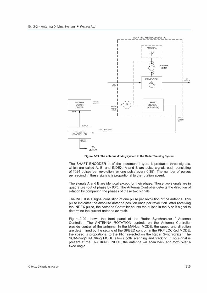
Figure 2-19. The antenna driving system in the Radar Training System.
The SHAFT ENCODER is of the incremental type. It produces three signals, which are called A, B, and INDEX. A and B are pulse signals each consisting of 1024 pulses per revolution, or one pulse every 0.35°. The number of pulses per second in these signals is proportional to the rotation speed.
The signals A and B are identical except for their phase. These two signals are in quadrature (out of phase by 90°). The Antenna Controller detects the direction of rotation by comparing the phases of these two signals.
The INDEX is a signal consisting of one pulse per revolution of the antenna. This pulse indicates the absolute antenna position once per revolution. After receiving the INDEX pulse, the Antenna Controller counts the pulses in the A or B signal to determine the current antenna azimuth.
Figure 2-20 shows the front panel of the Radar Synchronizer / Antenna Controller. The ANTENNA ROTATION controls on the Antenna Controller provide control of the antenna. In the MANual MODE, the speed and direction are determined by the setting of the SPEED control. In the PRF LOCKed MODE, the speed is proportional to the PRF selected on the Radar Synchronizer. The SCANning/TRACKing MODE allows both scanning and tracking. If no signal is present at the TRACKING INPUT, the antenna will scan back and forth over a fixed angle.
Ex. 2-2 – Antenna Driving System Discussion
116 © Festo Didactic 38542-00
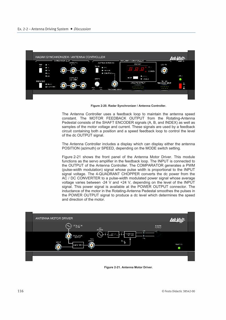
Figure 2-20. Radar Synchronizer / Antenna Controller.
The Antenna Controller uses a feedback loop to maintain the antenna speed constant. The MOTOR FEEDBACK OUTPUT from the Rotating-Antenna Pedestal consists of the SHAFT ENCODER signals (A, B, and INDEX) as well as samples of the motor voltage and current. These signals are used by a feedback circuit containing both a position and a speed feedback loop to control the level of the dc OUTPUT signal.
The Antenna Controller includes a display which can display either the antenna POSITION (azimuth) or SPEED, depending on the MODE switch setting.
Figure 2-21 shows the front panel of the Antenna Motor Driver. This module functions as the servo amplifier in the feedback loop. The INPUT is connected to the OUTPUT of the Antenna Controller. The COMPARATOR generates a PWM (pulse-width modulation) signal whose pulse width is proportional to the INPUT signal voltage. The 4-QUADRANT CHOPPER converts the dc power from the AC / DC CONVERTER to a pulse-width modulated power signal whose average voltage varies between -24 V and +24 V, depending on the level of the INPUT signal. This power signal is available at the POWER OUTPUT connector. The inductance of the motor in the Rotating-Antenna Pedestal smoothes the pulses in the POWER OUTPUT signal to produce a dc level which determines the speed and direction of the motor.
Figure 2-21. Antenna Motor Driver.

Ex. 2-2 – Antenna Driving System Procedure Outline
© Festo Didactic 38542-00 117
The Procedure is divided into the following sections:
Setting up the driving system of the Radar Antenna
The various rotation modes of the Radar Antenna
The SHAFT ENCODER of the Rotating-Antenna Pedestal
The servo amplifier of the Radar Antenna driving system (optional)
Setting up the driving system of the Radar Antenna
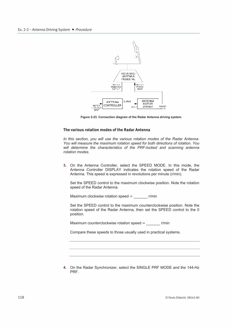
In this section, you will set up the driving system of the Radar Antenna. The connection diagram is shown in Figure 2-23.
1. The main elements of the Radar Training System, that is the antenna and its pedestal, the target table and the training modules, must be set up properly before beginning this exercise. Refer to Appendix B of this manual for setting up the Radar Training System, if this is not done yet.
Set up the modules on the Power Supply / Antenna Motor Driver as shown in Figure 2-22.
Figure 2-22. Module Arrangement.
On the Antenna Controller, make sure that the MANual ANTENNA ROTATION MODE is selected and that the SPEED control is in the 0 position.
Set the POWER switch of the Power Supply to the I (on) position, and then that of the Radar Synchronizer / Antenna Controller.
2. Connect the modules as shown in Figure 2-23.
PROCEDURE OUTLINE
PROCEDURE
Ex. 2-2 – Antenna Driving System Procedure
118 © Festo Didactic 38542-00
Figure 2-23. Connection diagram of the Radar Antenna driving system.
The various rotation modes of the Radar Antenna
In this section, you will use the various rotation modes of the Radar Antenna. You will measure the maximum rotation speed for both directions of rotation. You will determine the characteristics of the PRF-locked and scanning antenna rotation modes.
3. On the Antenna Controller, select the SPEED MODE. In this mode, the Antenna Controller DISPLAY indicates the rotation speed of the Radar Antenna. This speed is expressed in revolutions per minute (r/min).
Set the SPEED control to the maximum clockwise position. Note the rotation speed of the Radar Antenna.
Maximum clockwise rotation speed r/min
Set the SPEED control to the maximum counterclockwise position. Note the rotation speed of the Radar Antenna, then set the SPEED control to the 0 position.
Maximum counterclockwise rotation speed r/min
Compare these speeds to those usually used in practical systems.
4. On the Radar Synchronizer, select the SINGLE PRF MODE and the 144-Hz PRF.

Ex. 2-2 – Antenna Driving System Procedure
© Festo Didactic 38542-00 119
On the Antenna Controller, select the PRF LOCKed ANTENNA ROTATION MODE. The Radar Antenna should start to rotate. In which direction does the Radar Antenna rotate?
5. Note the rotation speed of the Radar Antenna in the appropriate row of the ROTATION SPEED column of Table 2-2.
Calculate the number of pulses per revolution of the Radar Antenna. Note the result in the appropriate row of the PULSES PER REVOLUTION column of Table 2-2.
Knowing that the beamwidth of the Radar Antenna is approximately 6°, calculate the number of pulses per antenna beamwidth. Note the results in the appropriate row of the PULSES PER ANTENNA BEAMWIDTH column of Table 2-2.
Table 2-2. Rotation speed, pulses per revolution, and pulses per antenna beamwidth for various PRFs.
PRF ROTATION SPEED PULSES PER REVOLUTION
PULSES PER ANTENNA
BEAMWIDTH
Hz r/min - -
144
216
288
6. On the Radar Synchronizer, successively select the 216- and 288-Hz PRFs. For each PRF, repeat the previous step.
From the results you noted in Table 2-2, determine the relationship between the PRF and the rotation speed of the Radar Antenna in the PRF LOCKed MODE. Explain.
Ex. 2-2 – Antenna Driving System Procedure
120 © Festo Didactic 38542-00
From the results you noted in Table 2-2, what important task is achieved by locking the rotation speed of the Radar Antenna on the PRF?
7. On the Antenna Controller, select the SCANning/TRACKing ANTENNA ROTATION MODE, then set the SPEED control so that the rotation speed of the Radar Antenna is approximately 6 r/min.
Describe the movement of the Radar Antenna.
On the Antenna Controller, set the SPEED control so that the rotation speed of the Radar Antenna is approximately 1 r/min, then select the POSITION MODE.
Observe the Antenna Controller DISPLAY to determine the azimuths covered by each scan of the Radar Antenna, and determine the scanning angle.
The SHAFT ENCODER of the Rotating-Antenna Pedestal
In this section, you will observe the A, B, and INDEX signals of the SHAFT ENCODER of the Rotating-Antenna Pedestal in order to understand how it operates. You will also determine the number of pulses per revolution produced by the SHAFT ENCODER, by measuring the frequency of signals A and B for a known rotation speed.
8. On the Antenna Controller, set the SPEED control to the 0 position and select the MANual ANTENNA ROTATION MODE. Select the SPEED MODE, then set the SPEED control so that the Radar Antenna rotates clockwise at approximately 5 r/min.

Ex. 2-2 – Antenna Driving System Procedure
© Festo Didactic 38542-00 121
Connect signals A and B of the SHAFT ENCODER in the Rotating-Antenna Pedestal to channels 1 and 2 of the oscilloscope, respectively, using probes. Make the appropriate settings on the oscilloscope to obtain a stable display. Figure 2-24 shows an example of what you might observe on the oscilloscope screen.
a A slight phase jitter may be noticeable on these signals.
Figure 2-24. Signals A and B of the SHAFT ENCODER when the Radar Antenna rotates clockwise at a speed of approximately 5 r/min.
9. On the Antenna Controller, use the SPEED control to increase the rotation speed of the Radar Antenna to 15 r/min, then decrease it to 5 r/min, while observing signals A and B on the oscilloscope screen.
What is the relationship between the rotation speed of the Radar Antenna and the frequency of signals A and B of the SHAFT ENCODER?
What is the phase relationship between signals A and B of the SHAFT ENCODER?
Ex. 2-2 – Antenna Driving System Procedure
122 © Festo Didactic 38542-00
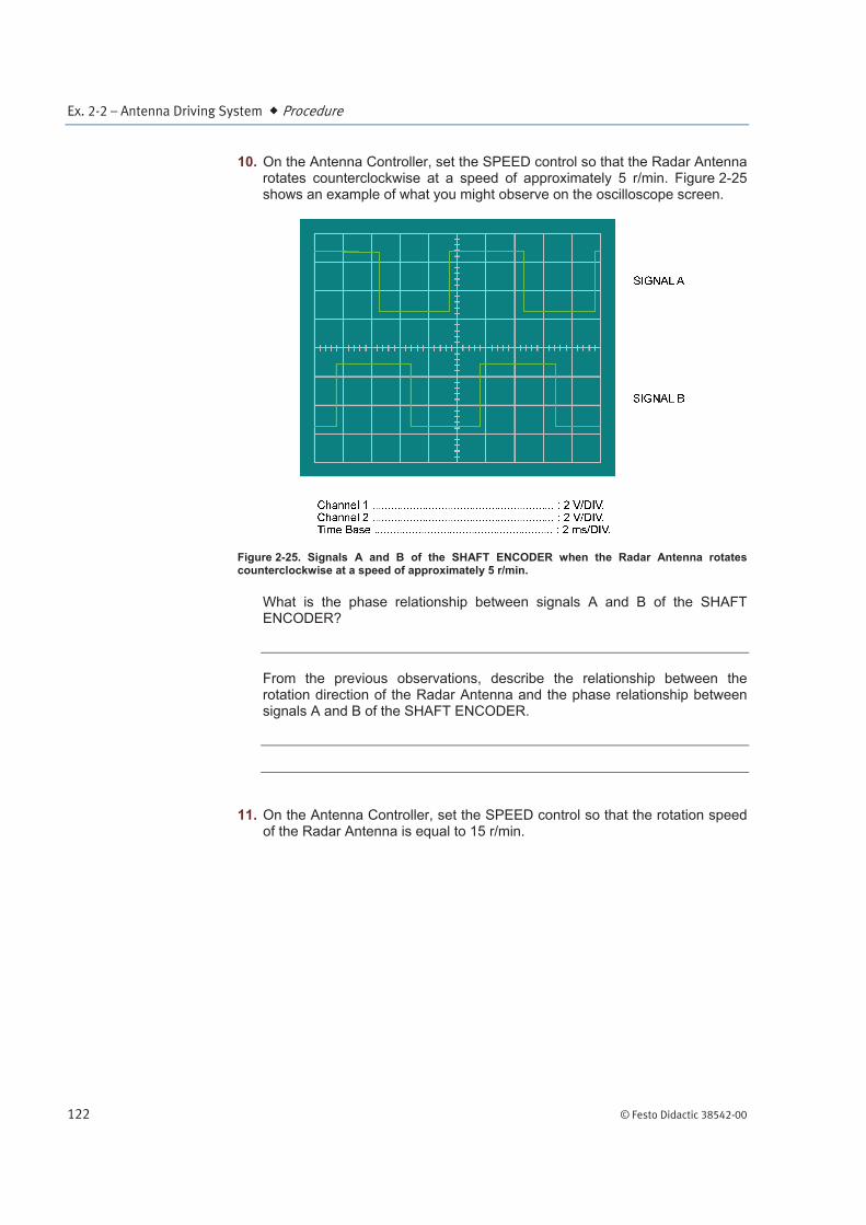
10. On the Antenna Controller, set the SPEED control so that the Radar Antenna rotates counterclockwise at a speed of approximately 5 r/min. Figure 2-25 shows an example of what you might observe on the oscilloscope screen.
Figure 2-25. Signals A and B of the SHAFT ENCODER when the Radar Antenna rotates counterclockwise at a speed of approximately 5 r/min.
What is the phase relationship between signals A and B of the SHAFT ENCODER?
From the previous observations, describe the relationship between the rotation direction of the Radar Antenna and the phase relationship between signals A and B of the SHAFT ENCODER.
11. On the Antenna Controller, set the SPEED control so that the rotation speed of the Radar Antenna is equal to 15 r/min.
Ex. 2-2 – Antenna Driving System Procedure
© Festo Didactic 38542-00 123
Determine the frequency of SHAFT ENCODER signals A and B using the oscilloscope or, if available, a frequency counter.
Frequency of SHAFT ENCODER signals A and B (15 r/min) Hz
Using the previous information, determine the number of pulses per revolution produced by the SHAFT ENCODER.
12. Disconnect signals A and B of the SHAFT ENCODER from channels 1 and 2 of the oscilloscope. Connect the INDEX signal of the SHAFT ENCODER to channel 1 of the oscilloscope.
On the Antenna Controller, set the SPEED control so that the rotation speed of the Radar Antenna is equal to 4 r/min.
Make the appropriate settings on the oscilloscope. You should observe a dc voltage of approximately 5 V which briefly goes to approximately 0 V from time to time.
Observe this signal and the movement of the Radar Antenna, then determine how these are related.
What is the role of the INDEX signal of the SHAFT ENCODER?
Ex. 2-2 – Antenna Driving System Procedure
124 © Festo Didactic 38542-00
The servo amplifier of the Radar Antenna driving system (optional)
In this section, you will observe various signals from the Antenna Motor Driver in order to understand how this module, the servo amplifier of the Radar Antenna driving system, operates. You will establish the relationship between these signals, and the rotation speed and direction of the Radar Antenna.
a This part of the exercise is optional, since it bears specifically on the operation of the servo amplifier in the Radar Antenna driving system, and because most antenna driving systems do not have a feedback loop. A basic knowledge of the operation of some simple electronic devices is required to carry out this part of the exercise.
13. Disconnect the INDEX signal of the SHAFT ENCODER from channel 1 of the oscilloscope.
Disconnect the cable connected to the INPUT of the Antenna Motor Driver, install a BNC T-connector on this input, then reconnect the loose end of the cable to one end of the BNC T-connector.
Connect the INPUT and the OSCILLATOR OUTPUT of the Antenna Motor Driver to channels 1 and 2 of the oscilloscope, respectively.
Adjust the oscilloscope as follows:
Channel 1 ...................................................... 5 V/DIV (DC coupled) Channel 2 ...................................................... 5 V/DIV (DC coupled) Time Base ...................................................... 10 s/DIV Vertical Mode ................................................. ALT Trigger ........................................................... Channel 2
On the Antenna Controller, use the SPEED control to vary the rotation direction and speed of the Radar Antenna, while observing the signal at the INPUT of the Antenna Motor Driver on the oscilloscope screen.
Determine the relationship between the polarity and level of the signal at the INPUT of the Antenna Motor Driver, and the rotation direction and speed of the Radar Antenna.
14. On the Antenna Controller, set the SPEED control so that the Radar Antenna rotates clockwise at a maximum speed.
Ex. 2-2 – Antenna Driving System Procedure
© Festo Didactic 38542-00 125
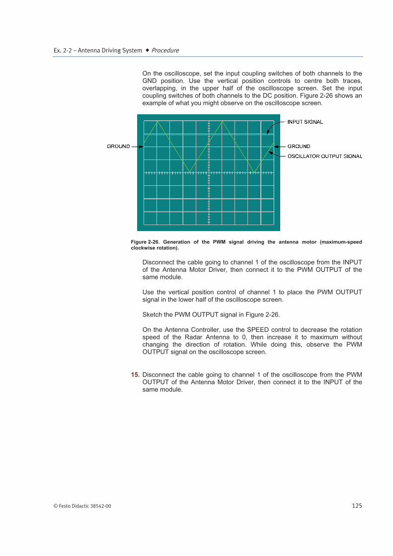
On the oscilloscope, set the input coupling switches of both channels to the GND position. Use the vertical position controls to centre both traces, overlapping, in the upper half of the oscilloscope screen. Set the input coupling switches of both channels to the DC position. Figure 2-26 shows an example of what you might observe on the oscilloscope screen.
Figure 2-26. Generation of the PWM signal driving the antenna motor (maximum-speed clockwise rotation).
Disconnect the cable going to channel 1 of the oscilloscope from the INPUT of the Antenna Motor Driver, then connect it to the PWM OUTPUT of the same module.
Use the vertical position control of channel 1 to place the PWM OUTPUT signal in the lower half of the oscilloscope screen.
Sketch the PWM OUTPUT signal in Figure 2-26.
On the Antenna Controller, use the SPEED control to decrease the rotation speed of the Radar Antenna to 0, then increase it to maximum without changing the direction of rotation. While doing this, observe the PWM OUTPUT signal on the oscilloscope screen.
15. Disconnect the cable going to channel 1 of the oscilloscope from the PWM OUTPUT of the Antenna Motor Driver, then connect it to the INPUT of the same module.

Ex. 2-2 – Antenna Driving System Procedure
126 © Festo Didactic 38542-00
Repeat step 14, but with the Radar Antenna rotating counterclockwise, and using Figure 2-27.
Figure 2-27. Generation of the PWM signal driving the antenna motor (maximum-speed counterclockwise rotation).
Briefly describe how the PWM OUTPUT signal is generated.
Determine the relationship between the PWM OUTPUT signal, and the rotation direction and speed of the Radar Antenna.
16. Disconnect the cables connected to channels 1 and 2 of the oscilloscope.
Connect TP4 and TP3 of the Antenna Motor Driver to channels 1 and 2 of the oscilloscope, respectively, using X10 probes.
Adjust the oscilloscope as follows:
Channel 1 ...................................................... 1 V/DIV (Set to GND) Channel 2 ...................................................... 1 V/DIV (Set to GND) Vertical Mode ................................................. ADD
Ex. 2-2 – Antenna Driving System Procedure
© Festo Didactic 38542-00 127
Notice that the effective sensitivity of the oscilloscope channels is 10 V/DIV, since X10 probes are used.
Invert the polarity of channel 2, set the vertical position controls so that the trace is centred on the oscilloscope screen, then set the input coupling switches of both channels to the DC position. This displays a signal whose voltage V = VTP4 VTP3.
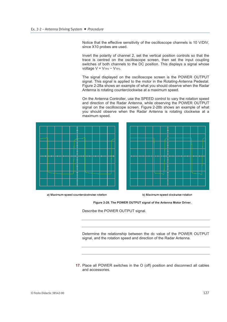
The signal displayed on the oscilloscope screen is the POWER OUTPUT signal. This signal is applied to the motor in the Rotating-Antenna Pedestal. Figure 2-28a shows an example of what you should observe when the Radar Antenna is rotating counterclockwise at a maximum speed.
On the Antenna Controller, use the SPEED control to vary the rotation speed and direction of the Radar Antenna, while observing the POWER OUTPUT signal on the oscilloscope screen. Figure 2-28b shows an example of what you should observe when the Radar Antenna is rotating clockwise at a maximum speed.
Figure 2-28. The POWER OUTPUT signal of the Antenna Motor Driver.
Describe the POWER OUTPUT signal.
Determine the relationship between the dc value of the POWER OUTPUT signal, and the rotation speed and direction of the Radar Antenna.
17. Place all POWER switches in the O (off) position and disconnect all cables and accessories.

Ex. 2-2 – Antenna Driving System Conclusion
128 © Festo Didactic 38542-00
In this exercise, you observed that the Radar Antenna can rotate continuously in both directions, or scan back and forth over 120 at a variable speed (MANual and SCANning ANTENNA ROTATION MODE). You also observed that, in the PRF LOCKed ANTENNA ROTATION MODE, the rotation speed of the Radar Antenna is proportional to the PRF. This ensures that each target is illuminated by the same number of pulses.
You verified that the frequency of signals A and B of the SHAFT ENCODER is proportional to the rotation speed of the Radar Antenna. You found that signal A lags signal B by 90 when the Radar Antenna rotates clockwise and vice versa. You also found that the INDEX signal of the SHAFT ENCODER is an absolute position reference for determining the absolute position of the Radar Antenna.
In the optional part of this exercise, you observed that the rotation direction of the Radar Antenna depends on the polarity of the signal at the INPUT of the Antenna Motor Driver, and that the rotation speed of the Radar Antenna is proportional to the dc level of this signal. You saw that the INPUT signal of the Antenna Motor Driver is converted into a 0- to 5-V PWM signal, then into a 24-V peak bipolar PWM signal (POWER OUTPUT signal). You found that the rotation direction of the Radar Antenna depends on the polarity of the dc value of the 24-V peak bipolar PWM signal, and that the rotation speed of the Radar Antenna is proportional to this dc value.
1. What is the role of the position transducer in an antenna driving system?
2. What is the range of antenna rotation speeds generally used in practical systems?
3. State two ways used to maintain the antenna speed proportional to the PRF.
CONCLUSION
REVIEW QUESTIONS

Ex. 2-2 – Antenna Driving System Review Questions
© Festo Didactic 38542-00 129
4. Describe the operation of the two types of shaft encoder generally used.
5. What is the purpose of the rotary joint?