Exemple de Calcul Motoare
11
G-2 ORIENTAL MOTOR GENERAL CATALOGUE T e c h n i c a l R e f e r e c e Motor Sizing Calculations Selecting a motor that sufficiently satisfies the specifications required by the equipment is an important key to ensuring the desired reliability and economy of the equipment. This section describes the procedure to select the optimum motor for a particular application, as well as the selection calculation s, key points of selection and examples. Selection Procedure An overview of selection procedure is explained below. First, determine the drive mechanism. Representative drive mechanisms include simple body of rotation, ball screw, belt pulley, and rack and pinion. Along with the type of drive mechanism, you must also determine the mass of transferred work, dimensions of each part, friction coefficient of the sliding surface, and so on. Confirm the drive conditions such as the speed of movement, drive time, and also positioning distance and period if positioning operation will be performed. Also confirm the stop accuracy, resolution, position holdi ng, operating voltage, operating environment, and so on. Calculate the values for load torque and load inertia at the motor drive shaft. See the left column on page G-3 for the calculation of load torque for representative mechanisms. See the right column on page G-3 for the calculation of inertia for representative shapes. Select a motor type from AC Motors, Brushless DC Motors or Stepping Motors based on the required specifications. Make a final determination of the motor after confirming that the specifications of the selected motor/gearhead satisfy all of the requirements, such as mechanical strength, acceleration period and acceleration torque. Since the specific items that must be checked will vary depending on the motor model, see the selection calculations and selection points explained on page G-4 and subsequent pages. Determine the drive mechanism component Confirm the required specifications (Equipment specifications) Calculate the speed and load Select motor type Selection calculation
-
Upload
ghinet-marius -
Category
Documents
-
view
242 -
download
0
Transcript of Exemple de Calcul Motoare

8/8/2019 Exemple de Calcul Motoare
http://slidepdf.com/reader/full/exemple-de-calcul-motoare 1/10G-2 ORIENTAL MOTOR GENERAL CATALOGUE
T e ch ni c al R ef er en c e
Motor Sizing Calculations
Selecting a motor that sufficiently satisfies the specifications required by the equipment is an important key to ensuring the desired reliability
and economy of the equipment.
This section describes the procedure to select the optimum motor for a particular application, as well as the selection calculations, key points
of selection and examples.
Selection ProcedureAn overview of selection procedure is explained below.
First, determine the drive mechanism. Representative drive mechanisms include simple body of rotation, ball
screw, belt pulley, and rack and pinion. Along with the type of drive mechanism, you must also determine the
mass of transferred work, dimensions of each part, friction coefficient of the sliding surface, and so on.
Confirm the drive conditions such as the speed of movement, drive time, and also positioning distance and
period if positioning operation will be performed. Also confirm the stop accuracy, resolution, position holding,
operating voltage, operating environment, and so on.
Calculate the values for load torque and load inertia at the motor drive shaft. See the left column on page G-3 forthe calculation of load torque for representative mechanisms. See the right column on page G-3 for the
calculation of inertia for representative shapes.
Select a motor type from AC Motors, Brushless DC Motors or Stepping Motors based on the required
specifications.
Make a final determination of the motor after confirming that the specifications of the selected motor/gearhead
satisfy all of the requirements, such as mechanical strength, acceleration period and acceleration torque. Since
the specific items that must be checked will vary depending on the motor model, see the selection calculations
and selection points explained on page G-4 and subsequent pages.
Determine the drive
mechanism component
Confirm the required specifications
(Equipment specifications)
Calculate the speed and load
Select motor type
Selection calculation

8/8/2019 Exemple de Calcul Motoare
http://slidepdf.com/reader/full/exemple-de-calcul-motoare 2/10G-3
T e ch ni c al R ef er en c e
Service Life
Motor and
Fan Sizing
Standard
AC Motors
Brushless
DC Motors
Stepping
Motors
Gearheads
Linear
Motion
Fan Motors
Formulas for Calculating Load TorqueCalculate the friction torque for the applicable drive mechanism.
Ball Screw
Pulley
Wire Belt Mechanism, Rack and Pinion Mechanism
By Actual Measurement
F =Force of moving direction [N]
F 0 =Pilot pressure load [N] (1/3F)
0 =Internal friction coefficient of pilot pressure nut (0.10.3)
=Efficiency (0.850.95)
i =Gear ratio (This is the gear ratio of the mechanism and not
the gear ratio of the Oriental Motor gearhead you are
selecting.)
PB =Ball screw pitch [m/rev]
F A =External force [N]
F B =Force when main shaft begins to rotate [N]
( F B= [value for spring balance] (kg) g [m/s2])
m =Total mass of work and table [kg]
=Frictional coefficient of sliding surfaces (0.05)
=Angle of inclination [˚ ]
D =Final pulley diameter [m]
g =Gravitational acceleration [m/s2] (9.807)
F B
D
M a c h i n e
Pulley
Spring Balance
= [Nm] yT L F B D
2
m F A
D
F m F A
D
F
= [Nm] rT L F
2 =
FD
2 i
D
i
= F Am g (sin a cos a) [N] t F
m F A
D
= T L D
i
F Am g
2
= [Nm] e( F Am g) D
2i
F A m
Direct Coupling
F A
F
m
= ( ) [Nm] qT L FPB
2 2
1
i
0 F 0 PB
= F Am g (sin a cos a) [N] w F
Formulas for Calculating Moment of InertiaInertia of a Cylinder
Inertia of a Hollow Cylinder
Inertia for Off-center Axis of Rotation
Inertia of a Rectangular Pillar
Inertia of an Object in Linear Motion
Density
Iron =7.9103 [kg/m3]
Aluminum =2.8103 [kg/m3]
Bronze =8.5103
[kg/m3
]Nylon =1.1103 [kg/m3]
Jx =Inertia on x axis [kgm2]
Jy =Inertia on y axis [kgm2]
J 0 =Inertia on x0 axis (passing through center
of gravity) [kgm2]
m =Mass [kg]
D1 =External diameter [m]
D2 =Internal diameter [m]
=Density [kg/m3]
L =Length [m]
A=Unit of movement [m/rev]
[kgm2] !4 J = m ( ) 2
2
A
A B
C
x
y
= [kgm2] !2 Jx m ( A2 B2)=12
1 ABC ( A2 B2)
12
1
= [kgm2] !3 Jy m ( B2C2)=12
1 ABC ( B2C2)
12
1
C
A B
x x0
= Jx0 [kgm2] !1 Jx ml2= m ( A2 B212l2)12
1
r= Distance between x and x0 axes [m]
L
D1
D2
x
y
= [kgm2] o Jx m ( D12 D2
2)=8
1 L ( D1
4 D24)
32
= [kgm2] !0 Jy m4
1( )
4
D12 D2
2
3
L2
D1
L
x
y
= [kgm2] u Jx mD12
8
1= LD1
4
32
= [kgm2] i Jy m4
1( )
4
D12
3
L2

8/8/2019 Exemple de Calcul Motoare
http://slidepdf.com/reader/full/exemple-de-calcul-motoare 3/10G-4 ORIENTAL MOTOR GENERAL CATALOGUE
T e ch ni c al R ef er en c e
Motor Sizing CalculationsThe following explains the calculation for selecting a stepping
motor based on pulse control:
Operating PatternsThere are 2 basic motion profiles. One is a start/stop operation
and the other is an acceleration/deceleration operation.
Acceleration/deceleration operation is the most common. When
load inertia is small, start/stop operation can be used.
Calculate the Number of Operating Pulses AThe number of operating pulses is expressed as the number of
pulse signals that adds up to the angle that the motor must move
to get the work from point A to point B.
Calculate the Operating Pulse Speed f 2
The operating pulse speed can be found from the number of
operating pulses, the positioning period and the
acceleration/deceleration period.
qFor Acceleration/Deceleration Operation
The level of acceleration (deceleration) period is an important
point in the selection. The acceleration (deceleration) period
cannot be set hastily, because it correlates with the acceleration
torque and acceleration/deceleration rate.Initially, set the acceleration (deceleration) period at roughly 25%
of the positioning period. (The setting must be fine-tuned before
the final decision can be made.)
Acceleration (Deceleration) Period [s] =Positioning Period [s]0.25
wFor Start-Stop Operation
Calculate the Acceleration/Deceleration Rate T R The values represent the specifications of Oriental Motor
controllers.
The acceleration/deceleration rate indicates the degree of
acceleration of pulse speed and is calculated using the equation
shown below:
t1
T R
PulseSpeed
[ k
H z]
=
Acceleration/ deceleration
rate T R
[ms/kHz]
✽Calculate the pulse speed in full-step equivalents.
Operating Pulse
Speed[kHz]
Starting Pulse
Speed [kHz]
Acceleration (Deceleration)Period[ms]
= f 2 f 1
t1
=Operating PulseSpeed f 2[Hz]
Number of Operating Pulses
[Pulses]
Positioning Period [s]
= A
t0
=Operating Pulse
Speed f 2[Hz]
Number of Operating Pulses
[Pulses]Starting Pulse
Speed [Hz]
Acceleration(Deceleration)
Period [s]
Positioning Period[s]
Acceleration (Deceleration)Period [s]
=A f 1t1
t0t1
=
No. of PulsesRequired for1 Motor Rotation
Number of OperatingPulses A[Pulses]
Distance per MovementDistance per Motor Rotation
= : Step Anglel
lrev
360˚θ s
θ s
Positioning Period
Start/Stop Operation
Operating PulseSpeed
Number ofOperating Pulses
A
t 0
f 2
Positioning Period
Acceleration/Deceleration Operation
Acceleration Period t 1 t 1
t 0 DecelerationPeriod
Operating PulseSpeedf 2
f 1
Starting PulseSpeed
Number ofOperating Pulses
A
Calculate the Operating Speed from Operating Pulse speed
Calculate the Load TorqueSee basic equations on page G-3.
Calculate the Acceleration TorqueRegardless of the motor type, the acceleration/deceleration torque
must always be set if the speed is to be varied.
The basic equation is the same for all motors. However, different
equations apply to stepping motors, as shown below, because the
specifications of stepping motors are often calculated on the basis
of pulse speed.
<Standard AC Motors> (The same equation applies to brushless
DC motors.)
<Stepping Motors>
qFor Acceleration/Deceleration Operation
wFor Start-Stop Operation
Calculate the Required Torque T M
The required torque is calculated by multiplying the sum of load
torque and acceleration torque by the safety factor.
Required Torque T M= (Load Torque Acceleration Torque) Safety Factor
=(T LT a)S f
=
Acceleration TorqueT a [Nm]
Rotor Inertia[kgm2]
Total Inertia[kgm2]
Step Angle[˚ ](Operating Pulse Speed)2 [Hz]
180˚coefficient
= ( J 0 J L) s f 22
180n n: 3.6 ̊/ sθ
θ
=
Acceleration TorqueT a [Nm]
Rotor Inertia[kgm2]
Total Inertia[kgm2]
Operating Pulse
Speed [Hz]
Starting Pulse
Speed [Hz]
Acceleration (Deceleration)Period [s]
Step Angle[˚ ]
180˚
= ( J 0 J L) f 2 f 1
t1
s
180
θ
Operating
Speed[r/min]
N M
AccelerationPeriod t 1
Deceleration
Period t 1Positioning Period t 0
For AC Motors
Movement
AccelerationTorqueT a[Nm]
=coefficient
Rotor Inertia[kgm2]
Total Inertia[kgm2] Operating Speed [r/min]
Acceleration (Deceleration)Period [s]
=9.55
( J 0 J L)
t1
N M
60Operating
Speed[r/min]=Operating Pulse Speed [Hz]
Step Angle
360
8/8/2019 Exemple de Calcul Motoare
http://slidepdf.com/reader/full/exemple-de-calcul-motoare 4/10G-5
T e ch ni c al R ef er en c e
Service Life
Motor and
Fan Sizing
Standard
AC Motors
Brushless
DC Motors
Stepping
Motors
Gearheads
Linear
Motion
Fan Motors
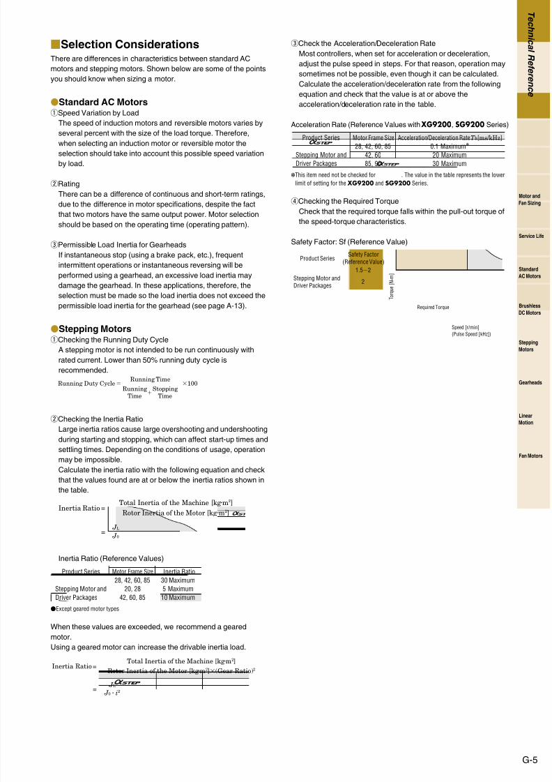
Selection ConsiderationsThere are differences in characteristics between standard AC
motors and stepping motors. Shown below are some of the points
you should know when sizing a motor.
Standard AC MotorsqSpeed Variation by Load
The speed of induction motors and reversible motors varies by
several percent with the size of the load torque. Therefore,when selecting an induction motor or reversible motor the
selection should take into account this possible speed variation
by load.
wRating
There can be a difference of continuous and short-term ratings,
due to the difference in motor specifications, despite the fact
that two motors have the same output power. Motor selection
should be based on the operating time (operating pattern).
ePermissible Load Inertia for Gearheads
If instantaneous stop (using a brake pack, etc.), frequent
intermittent operations or instantaneous reversing will be
performed using a gearhead, an excessive load inertia maydamage the gearhead. In these applications, therefore, the
selection must be made so the load inertia does not exceed the
permissible load inertia for the gearhead (see page A-13).
Stepping MotorsqChecking the Running Duty Cycle
A stepping motor is not intended to be run continuously with
rated current. Lower than 50% running duty cycle is
recommended.
wChecking the Inertia Ratio
Large inertia ratios cause large overshooting and undershooting
during starting and stopping, which can affect start-up times and
settling times. Depending on the conditions of usage, operation
may be impossible.
Calculate the inertia ratio with the following equation and check
that the values found are at or below the inertia ratios shown in
the table.
Inertia Ratio (Reference Values)
Except geared motor types
When these values are exceeded, we recommend a geared
motor.
Using a geared motor can increase the drivable inertia load.
=Inertia RatioTotal Inertia of the Machine [kgm2]
Rotor Inertia of the Motor [kgm2](Gear Ratio)2
= J L J 0 i2
Product Series Motor Frame Size
Stepping Motor and
Driver Packages
28, 42, 60, 85
20, 28
42, 60, 85
Inertia Ratio
30 Maximum
5 Maximum
10 Maximum
=Inertia RatioTotal Inertia of the Machine [kgm2]
Rotor Inertia of the Motor [kgm2]
= J L
J 0
Running Duty Cycle 100Running Time
RunningTime
StoppingTime
eCheck the Acceleration/Deceleration Rate
Most controllers, when set for acceleration or deceleration,
adjust the pulse speed in steps. For that reason, operation may
sometimes not be possible, even though it can be calculated.
Calculate the acceleration/deceleration rate from the following
equation and check that the value is at or above the
acceleration/deceleration rate in the table.
Acceleration Rate (Reference Values with XG9200, SG9200 Series)
✽This item need not be checked for . The value in the table represents the lower
limit of setting for the XG9200 and SG9200 Series.
rChecking the Required Torque
Check that the required torque falls within the pull-out torque of
the speed-torque characteristics.
Safety Factor: Sf (Reference Value)
Required Torque
Speed [r/min]
(Pulse Speed [kHz])
T o r q u e
[ N
m ]
Product Series
Stepping Motor andDriver Packages
Safety Factor(Reference Value)
1.52
2
Product Series Motor Frame Size Acceleration/Deceleration RateT R[ms/kHz]28, 42, 60, 85
42, 60
85, 90
0.1 Maximum✽20 Maximum
30 Maximum
Stepping Motor and
Driver Packages

8/8/2019 Exemple de Calcul Motoare
http://slidepdf.com/reader/full/exemple-de-calcul-motoare 5/10G-6 ORIENTAL MOTOR GENERAL CATALOGUE
T e ch ni c al R ef er en c e
Sizing Example
Ball Screw
Determine the Drive Mechanism
Total mass of the table and work ·····································m=40 kg
Frictional coefficient of sliding surfaces ·······························=0.05
Ball screw efficiency ····························································· =0.9
Internal frictional coefficient of pilot pressure nut ·················0=0.3Ball screw shaft diameter············································· D B=15 mm
Total length of ball screw ············································ L B=600 mm
Material of ball screw ·················Iron (density =7.9103 [kg/m3])
Ball screw pitch ···························································· P B=15 mm
Desired resolution···············································∆l=0.03 mm/step
(feed per pulse)
Feed ·············································································l=180 mm
Positioning period ·············································t0=Within 0.8 sec.
Calculate the Required Resolution
can be connected directly to the application.
Determine the Operating Pattern (See page G-4 for basic equations)
(1) Finding the Number of Operating Pulses A [pulses]
(2) Determine the Acceleration (Deceleration) Period t1 [s]
An acceleration (deceleration) period of 25% of the positioning
period is appropriate.
Acceleration (Deceleration) Period t1=0.80.25=0.2 [s]
(3) Determine the Operating Pulse Speed f 2 [Hz]
period [s]t 1 t 1
t 0=0.8
Ope
rating
pulse
speed
[ H
z]
10000
0.2 0.2
6000 pulses
=Operating pulse
speed f 2
Operating pulses ( A)Starting pulse speed ( f 1) Acceleration (Deceleration) Period (t1)
Positioning Period (t0) Acceleration (Deceleration) Period (t1)
=60000
0.80.2=10000 [Hz]
= Operating pulses AFeed per Unit (l)
Ball Screw Pitch ( PB)
360˚
Step Angle ( s)
= 180
15=6000 [pulses]
360˚
0.72˚
θ
=Required Resolution s360˚Desired Resolution (∆l)
Ball Screw Pitch ( PB)
= =0.72 [˚ ]360˚0.03
15
θ
P B
D B
SteppingMotor
Controller
Driver
Programmable
Controller
Coupling
DirectConnection
m
(4) Calculate the Operating Speed N [r/min]
Calculate the Required Torque T M [Nm] (see page G-4)
(1) Calculate the Load Torque T L [Nm]
(2) Calculate the Acceleration Torque T a [Nm]
qCalculate the total moment of inertia J L [kgm2
](See page G-3 for basic equations)
wCalculate the acceleration torque Ta [Nm]
(3) Calculate the Required Torque T M [Nm]
Required torque T M =(T LTa)2
={0.0567(628 J 00.158)}2
=1256 J 00.429 [Nm]
Select a Motor
(1) Provisional Motor Selection
(2) Determine the Motor from the Speed-Torque Characteristics
AS66AA
Select a motor for which the required torque falls within the pull-
out torque of the speed-torque characteristics.
01000 2000 3000 4000
Torque[kgfcm]
Torque[N
m]
Speed [r/min]
Pulse Speed [kHz]100 20 30 40 50 60
(Resolution Setting: 1000 P/R)
1.5
2.0
1.0
0.5
15
20
10
5
0
405107 AS66AA
Rotor Inertia[kgm2]
0.48
Required Torque[Nm]Model
=( J 0 J L ) Acceleration torque T a f 2 f 1
t1
s180˚
=( J 02.52104 )
=628 J 00.158 [Nm]
100000
0.2
0.72180˚
θ
=Inertia of Ball Screw J B
32 LB DB
4
=
=0.236104 [kgm2]
327.9103600103 (15103)4
=m (
=40(
)2
Inertia of Table and Work J T
= J B J T
=0.2361042.28104=2.52104 [kgm2]
Total Inertia J L
PB
2
2 =2.28104 [kgm2])
215103
=F Am g (sin a cos a)
=0409.807 (sin00.05cos0)
=19.6 [N]
Force of moving direction F
=Load Torque T L F PB
2
0 F 0 PB
2
=Pilot Pressure Load F 0 F
3=6.53 [N]=
19.6
3
=
=0.0567 [Nm]
19.615103
2 0.9
0.36.5315103
2
= f 2 60Operating SpeedS
360
=10000 600.72360
=1200 [r/min]
θ
Using Stepping Motors ( )

8/8/2019 Exemple de Calcul Motoare
http://slidepdf.com/reader/full/exemple-de-calcul-motoare 6/10G-7
T e ch ni c al R ef er en c e
Service Life
Motor and
Fan Sizing
Standard
AC Motors
Brushless
DC Motors
Stepping
Motors
Gearheads
Linear
Motion
Fan Motors
This example demonstrates how to select an AC motor with an
electromagnetic brake for use on a tabletop moving vertically on a
ball screw. In this case, a motor must be selected that meets the
following basic specifications.
<Required and Structural Specifications>
Total mass of the table and work ···································m=30 [kg]
Table speed ························································V =152 [mm/s]
External force····································································· F A=0[N]Ball screw tilt angle ····························································=90 [˚ ]
Total length of ball screw··········································· L B=800 [mm]
Ball screw shaft diameter············································ D B=20 [mm]
Ball screw pitch ····························································· P B=5 [mm]
Distance moved for one rotation of ball screw ················ A=5 [mm]
Ball screw efficiency ······························································· =0.9
Material of ball screw ·····················Iron (density =7.9103kg/m3)
Internal frictional coefficient of pilot pressure nut ·················0=0.3
Frictional coefficient of sliding surfaces································=0.05
Motor power supply ·························Single-Phase 110 VAC 60 Hz
Movement time ·····················Intermittent operation, 5 hours/day
Load with repeated starts and stops
Required load holding
Determine the Gear Ratio
Because the rated speed for a 4-pole motor at 60 Hz is
14501550 r/min,
From within this range a gear ratio of i =9 is selected.
Calculate the Required Torque
= F Am g (sin cos )
=0309.807 (sin90˚0.05cos90˚)
=294 [N]
Load weight in the directionof the ball screw shaft F
=Load torque T L F P B
2 2
2
0 F 0 P B
=Pilot pressure load F 0 F
3=98 [N]
=
=0.283 [Nm]
2945103
2 0.9
0.3985103
= =7.19.9
the gear ratio ( i ) is calculated as follows:
i14501550
N G=
14501550
18024
= =Speed at the gearhead output shaft: N GV 60
P
(152)60
5
=18024 [r/min]
Motor
Gearhead
Coupling
Ball Screw
Slide Guide
mv
FA
Using Standard AC Motors This value is the load torque at the gearhead drive shaft, and must
be converted into load torque at the motor output shaft.
The required torque at the motor output shaft (T M ) is given by:
Look for a margin of safety of 2 times.
38.82=77.6 [mNm]
To find a motor with a start-up torque of 77.6 mNm or more,
select motor 3RK15GN-AWMU.
This motor is equipped with an electromagnetic brake to hold a load.
A gearhead with a gear ratio of 1:9 that can be connected to the
motor 3RK15GN-AWMU is 3GN9K.
Load Inertia Check
Gearhead shaft total load inertia
J =0.9931040.190104=1.18104 [kgm2]
Here, the 3GN9K permissible load inertia is (see page A-13):
J G=0.1410492
J G=1.13103 [kgm2]
Therefore, J < J G, the load inertia is less than the permissible
inertia, so there is no problem. There is margin for the torque, sothe rotation rate is checked with the no-load rotation rate (about
1750 r/min).
This confirms that the motor meets the specifications.
=V N M P B
60 i17505609
=16.2 [mm/s]=
(where N M is the motor speed)
=Ball Screw Moment of Inertia J B
32 L B D B
4
=
=0.993104 [kg m2]
327.9103800103 (20103)4
=m ( ) 2Table and Work Moment of Inertia J m A
2
2=30 ( ) 2
=0.190104 [kg m2]
5103
=T M T L
i G= =0.0388 [Nm]=38.8 [mNm]
0.28390.81
(Gearhead transmission efficiency =0.81) G

8/8/2019 Exemple de Calcul Motoare
http://slidepdf.com/reader/full/exemple-de-calcul-motoare 7/10G-8 ORIENTAL MOTOR GENERAL CATALOGUE
T e ch ni c al R ef er en c e
Belt and Pulley
Here is an example of how to select an induction motor to drive a
belt conveyor.
In this case, a motor must be selected that meets the following
basic specifications.
<Required and Structural Specifications>
Total mass of belt and work ·············································m1=20kg
Frictional coefficient of sliding surfaces·································=0.3
Drum radius ·································································· D=100mm
Mass of drum·····································································m 2=1kg
Belt roller efficiency ······························································· =0.9Belt speed·························································V =140mm/s10%
Motor power supply·························Single-Phase 110 VAC 60 Hz
Movement time ··························································· 8 hours/day
Determine the Gear Ratio
Because the rated speed for a 4-pole motor at 60 Hz is
14501550 r/min,
From within this range a gear ratio of i =60 is selected.
Calculate the Required Torque
On a belt conveyor, the greatest torque is needed when starting
the belt. To calculate the torque needed for start-up, the friction
coefficient ( F ) of the sliding surface is first determined:
F =m g=0.3209.807=58.8 [N]
The load torque obtained is actually the load torque at the
gearhead drive shaft, so this value must be converted into load
torque at the motor output shaft. If the required torque at the motor
output shaft is T M , then:
Look for a margin of safety of 2 times, taking into consideration
commercial power voltage fluctuation.
82.62165 [mNm]
The suitable motor is one with a starting torque of 165 mNm or
more. Therefore, motor 5IK40GN-AWU is the best choice.
Since a gear ratio of 1:60 is required, select the gearhead
5GN60K which may be connected to the 5IK40GN-AWU
motor.
=T M T Li G
= =0.0826 [Nm]=82.6 [mNm]3.27
600.66
(Gearhead transmission efficiency G=0.66)
= =3.27 [Nm]Load torque T L F D
2 =
58.8100103
20.9
= =49.364.6
the gear ratio (i) is calculated as follows:
i
14501550
N G =
14501550
26.72.7
= =Speed at the gearhead output shaft: N GV 60
D
(14014) 60
100
=26.72.7 [r/min]
Belt Conveyor
Gearhead
Motor
D
V
Using Standard AC Motors
Load Inertia Check
Gearhead Shaft Load Inertia
J =50010412.51042=525104 [kgm2]
Here, the 5GN60K permissible load inertia is (see page A-13):
J G=0.75104602
=2700104 [kgm2]
Therefore, J < J G, the load inertia is less than the permissible
inertia, so there is no problem.
Since the motor selected has a rated torque of 260 mNm, which is
somewhat larger than the actual load torque, the motor will run at
a higher speed than the rated speed.
Therefore the speed is used under no-load conditions
(approximately 1750 r/min) to calculate belt speed, and thus
determine whether the selected product meets the required
specifications.
=V N M D
60 i=
1750 1006060
=152.7 [mm/s]
(Where N M is the motor speed)
=Roller Moment of Inertia J m218
m 2 D 2
=
=12.5104 [kgm2]
1
81 (100103)2
=m1 ( ) 2
Belt and Work Moment of Inertia J m1
D
2
=20 ( ) 2100103
2
=500104 [kgm2]

8/8/2019 Exemple de Calcul Motoare
http://slidepdf.com/reader/full/exemple-de-calcul-motoare 8/10G-9
T e ch ni c al R ef er en c e
Service Life
Motor and
Fan Sizing
Standard
AC Motors
Brushless
DC Motors
Stepping
Motors
Gearheads
Linear
Motion
Fan Motors
Here is an example of how to select a brushless DC motor to drive
a belt conveyor.
Performance
Belt speed V L is 0.015 m/s1 m/s
Specifications for belt and work
Condition: Motor power supply···················Single-Phase 100 VAC
Belt conveyor drive
Roller diameter ·············································· D=0.1m
Mass of roller ·················································m2=1kg
Total mass of belt and work·····························m1=15kg
Frictional coefficient of sliding surfaces ················=0.3
Belt roller efficiency ··············································· =0.9
Find the Required Speed Range
For the gear ratio, select 1:15 (speed range: 2200) from the
permissible torque table for combination type on page B-12 so that
the minimum/maximum speeds fall within the speed range.
Calculate the Load Inertia J G
Load Inertia of Roller: Jm2
Load inertia of belt and work: Jm1
The load inertia J G is calculated as follows:
J G= J m22 J m1=212.5104375104
=400104kgm2
From the specifications on page B-10, the permissible load inertia
for BX5120A-15 is 420104 kgm2
Calculate the Load Torque T L
Select BX5120A-15 from the permissible torque table on page
B-12.
Since the permissible torque is 5.4 Nm, the safety margin is
T M / T L=5.4/2.452.2.
Usually, a motor can operate at the safety margin of 1.52 or more.
=
=2.45 Nm
Load Torque T L
= m1 g=0.3159.807=44.1NFriction Coefficient of the Sliding Surface: F
F D
2
44.10.1
20.9
=m1 ( Jm1 D
2
2
0.1) =15 ( ) =375104 kgm2 2 2
= Jm218
m2 D 2=
18
10.1 2=12.5104 kgm2
= N G: Speed at the gearhead output shaft N G
Belt Speed
60V L
D
=2.86 r/min (Minimum Speed)0.015 m/s 600.015
0.1
=191 r/min (Maximum Speed)1 m/s 601
0.1
Work
Using Brushless DC Motors
The mass of work is selected that can be driven with SMK5100A-A
when the belt-drive table shown in Fig. 1 is driven in the operation
pattern shown in Fig. 2.
Structural Specifications
Total mass of belt and work m1=1.5 [kg]
Roller diameter D=30 [mm]
Mass of roller m 2=0.1 [kg]
Frictional coefficient of sliding surfaces =0.04
Belt and pulley efficiency =0.9
Frequency of power supply 60 Hz (Motor speed: 72 r/min)
Low-speed synchronous motors share the same basic operating
principle with 2-phase stepping motors. Accordingly, the torque for
a low-speed synchronous motor is calculated in the same manner
as for a 2-phase stepping motor.
qBelt speed
Check the belt (work) speed
wCalculate the Required Torque T L
Frictional coefficient of sliding surfaces: F = m1 g=0.041.59.807=0.589 [N]
eCalculate the Load Inertia
Load inertia of belt and work: Jm1
Load Inertia of Roller: Jm 2
The load inertia J L is calculated as follows:
J L= J m1 J m 22=3.381040.1131042=3.5104 [kgm2]
rCalculate the Acceleration Torque
Here, θ s=7.2˚, f=60 Hz, n=3.6˚/ θ s=0.5
J 0=Rotor Inertia
tCalculate the Required Torque (look for a margin of safety of 2 times)
Required Torque T M =(T LTa)2
=(9.82103905 J 00.32)2
=1810 J 00.66 [Nm]
ySelect a Motor
Select a motor that satisfies both the required torque and the
permissible load inertia.
When the required torque is calculated by substituting the rotor
inertia, T M is obtained as 0.914 Nm, which is below the output
torque. Next, check the permissible load inertia. Since the load
inertia calculated ine is also below the permissible load inertia,
SMK5100A-A can be used in this application.
Rotor Inertia
[kgm
2
]
Motor
1.4104
Permissible Load Inertia
[kgm
2
]
Output Torque
[Nm]
7104 1.12SMK5100A-A
Ta=( J 0 J L)
=905 J 00.32 [Nm]
=( J 03.5104)
sf
2
180 n 7.260
2
1800.5θ
J m2=18
m 2 D2= 18
0.1(30103)2=0.113104 [kgm2]
J m1= m1( D
2 2)2=1.5( )2=3.38104 [kgm2]
30103
T L=Load Torque F D
2 = =9.82103 [Nm]
0.58930103
20.9
V = = =113 [mm/s] D N
60
3072
60
CW
5 10 15 (sec)
Fig. 2 Operating Pattern
CCW
Roller 2
Fig. 1 Example of Belt Drive
Roller 1
m
F
Using Low-Speed Synchronous Motors (SMK Series)

8/8/2019 Exemple de Calcul Motoare
http://slidepdf.com/reader/full/exemple-de-calcul-motoare 9/10G-10 ORIENTAL MOTOR GENERAL CATALOGUE
T e ch ni c al R ef er en c e
Index TableGeared stepping motors are suitable for systems with high inertia,
such as index tables.
Determine the Drive Mechanism
Diameter of index table ················································ DT =300mm
Index table thickness ··························································· LT =10mm
Diameter of work ·································································· Dw=40mm
Thickness of work································································· Lw=30mm
Material of table·································Iron (density =7.9103kg/m3)
Number of loads ······················································10 (one every 36˚)
Distance from center of index table
to center of load ······································································ l=125mm
Positioning angle ··········································································· θ =36˚
Positioning period································································· t0=0.25 sec
The PN geared type (gear ratio=1:10, resolution=0.036˚)
can be used.
✽The PN geared type can be used at the maximumstarting/stopping torque in the inertial drive mode.
Gear Ratio ··············································································· i=10
Resolution·············································································θ s=0.036˚
Determine the Operating Pattern (See page G-4 for basic equations)
(1) Find the Number of Operating Pulses A [pulses]
(2) Determine the Acceleration (Deceleration) Period t 1 [s]
Generally, an acceleration (deceleration) period should be set
approximately 25% of the positioning period.
Here, t1= 0.1[s] is provided as the accelation (deceleration) period.
(3) Calculate the Operation Speed N [r/min]
✽The permissible speed range for a PN geared motor with a gear
ratio of 1:10 is 0 to 300 r/min.
= = Operation Speed N 60
360
60
360
θ
t0t1
36
0.250.1
=40 [r/min]
=Operating pulses Aθ
θ s
36˚
0.036˚=
=1000 [Pulses]
DT=300 mm
=125 mm
Programmable
ControllerGeared Stepping Motor
ControllerDriver
(4) Determine the Operating Pulse Speed f 2 [Hz]
Period [s]t1 t1
t0=0.25
Operating
Pulse
Speed
[ H
z]
6667
0.1 0.1
600 Pulses
= =Operating Pulse Speed f 2 A
t0t1
600
0.250.1
=6667 [Hz]

8/8/2019 Exemple de Calcul Motoare
http://slidepdf.com/reader/full/exemple-de-calcul-motoare 10/10
T e ch ni c al R ef er en c e
Service Life
Motor and
Fan Sizing
Standard
AC Motors
Brushless
DC Motors
Stepping
Motors
Gearheads
Linear
Motion
Fan Motors
Calculate the Required Torque T M [Nm] (see page G-4)
(1) Calculate the Load Torque T L [Nm]
Friction load is negligible and therefore omitted. The load torque is
assumed as zero.
Load Torque T L=0 [Nm]
(2) Calculate the Acceleration Torque T a [Nm]
qCalculate the total moment of inertia J L [kgm2]
(See page G-3 for basic equations)
Inertia of work J W [kgm2] relative to the center of rotation can be
obtained from distance L [mm] between the center of work and
center of rotation, mass of work mW [kg], and inertia of work
(center of gravity) J w1 [kgm2] .
Since the number of works, n, is 10 [pcs],
wCalculate the acceleration torque T a [Nm]
(3) Calculate the Required Torque T M
Safety Factor S f =2.0
Required Torque T M=(T LT a)S f
={0(4.19103 J 04.61)}2.0
=8.38103 J 09.2 [Nm]
=( J 0i2 J L) Acceleration
Torque T a
f 2 f 1
t1
s
180
=( J 010211102)
=4.19103 J 04.61 [Nm]
66670
0.1
0.036
180
θ
= J T J W
(6.284.71)102=
Total Inertia J L
=11102 [kgm2]
= n( J W1mW L 2)
10[(0.596104)0.3(125103)2]=
Inertia of Work J W
=4.71102 [kgm2]
(Center of gravity)
=Mass of Work mW
4 LW DW
2
=
=0.3 [kg]
47.9103(30103)(40103)2
=Inertia of Table J T
32 LT DT
4
=
32 LW DW
4
=
=6.28102 [kgm2]
327.9103(10103)(300103)4
=
327.9103(30103)(40103)4
Inertia of Work J W1
=0.596104 [kgm2]
(Center of gravity)
Select a Motor
(1) Provisional Motor Selection
(2) Determine the Motor from the Speed-Torque Characteristics
AS66AA-N10
Select a motor for which the required torque falls within the pull-
out torque of the speed-torque characteristics.
PN geared type can operate inertia load up to acceleration torque
less than Maximum torque.
If load torque is applied, the selection must be made so the
product of the load torque and the safety factor does not exceed
the permissible torque.
Pulse Speed [kHz]
(Resolution Setting: 1000P/R)
0 504540353020 2515105
15050 100 250200 300
Speed [r/min]
T o r q u e [ N
m ]
T o r q u e [ k g f c m ]
0
25
20
5
10
15
0
250
200
50
100
150
Permissible Torque
J0=405107 AS66AA-N10
Rotor Inertia[kgm2]
TM=9.55
Required Torque[Nm]Model