EXECUTIVE SUMMARY -...
20
1 EXECUTIVE SUMMARY 1. INTRODUCTION Badaun district, located on the left bank of river Ganga near Narora barrage has an area of 5168 Sq. Kms. The district forms part of the Western Region of Uttar Pradesh and divided into 5 tehsils. The command of the Badaun lift irrigation scheme falls in four tehsils ( namely Sahaswan, Bisauli, Bilsi and Sadar ) of Badaun district and in Gunnaur tehsil of Sambhal district. River Ganga flows in about 155 km in district Badaun & Gannaur Tehsil. The drainage system of district is through Mahawa river, Sot river, Kadwara drain and Aswar drain etc. The area on east & north side of Mahawa river are at higher elevation as compared to areas between Mahawa and Ganga. Marginal embankment along left bank of river Ganga has been constructed in about 105 km length to protect the Ganga Mahawa doab from floods. More than 75% of the population in the district is engaged in agriculture i.e. 65% as cultivators and remaining as agriculture labourers. Providing irrigation therefore is very important for economic upliftment of the people. The industrial development in the region in negligible barring few small scale industries. Due to high population in Badaun district, there is pressure on higher utilization of resources and more than 75% of area has been brought under cultivation in the district. The forest cover in the in the district is minimal (less than 1.5%). Project Proposal It is proposed to divert water from river Ganga at Narora barrage to provide irrigation in culturable command area of 139665 ha. The scheme envisages construction of a canal head regulator on upstream left bank of Narora Barrage to divert 102 cumec of water which includes 82.0 cumec for Irrigation and rest about 20 cumec for silt ejector provided at RD 120.0 to 150.0 m of Main Canal. From Narora barrage a gravity main canal of 20.05 km length will be constructed up to village Dhandwara on banks of river Mahawa. Irrigation in Ganga Mahawa doab will be provided by Sahaswan Branch canal taking off from main canal at 14.1 km. The remaining water will be lifted by 15.0 m at Dhandwara and delivered to second part of Main canal after crossing the river Mahawa. The main canal then flows as gravity and serves the irrigation demands of the uplands beyond the Mahawa river.
-
Upload
nguyenminh -
Category
Documents
-
view
222 -
download
0
Transcript of EXECUTIVE SUMMARY -...

1
EXECUTIVE SUMMARY
1. INTRODUCTION
Badaun district, located on the left bank of river Ganga near Narora barrage has an area of
5168 Sq. Kms. The district forms part of the Western Region of Uttar Pradesh and divided
into 5 tehsils. The command of the Badaun lift irrigation scheme falls in four tehsils ( namely
Sahaswan, Bisauli, Bilsi and Sadar ) of Badaun district and in Gunnaur tehsil of Sambhal
district. River Ganga flows in about 155 km in district Badaun & Gannaur Tehsil. The
drainage system of district is through Mahawa river, Sot river, Kadwara drain and Aswar
drain etc. The area on east & north side of Mahawa river are at higher elevation as
compared to areas between Mahawa and Ganga. Marginal embankment along left bank of
river Ganga has been constructed in about 105 km length to protect the Ganga Mahawa
doab from floods.
More than 75% of the population in the district is engaged in agriculture i.e. 65% as
cultivators and remaining as agriculture labourers. Providing irrigation therefore is very
important for economic upliftment of the people. The industrial development in the region in
negligible barring few small scale industries.
Due to high population in Badaun district, there is pressure on higher utilization of resources
and more than 75% of area has been brought under cultivation in the district. The forest
cover in the in the district is minimal (less than 1.5%).
Project Proposal
It is proposed to divert water from river Ganga at Narora barrage to provide irrigation in
culturable command area of 139665 ha. The scheme envisages construction of a canal
head regulator on upstream left bank of Narora Barrage to divert 102 cumec of water which
includes 82.0 cumec for Irrigation and rest about 20 cumec for silt ejector provided at RD
120.0 to 150.0 m of Main Canal. From Narora barrage a gravity main canal of 20.05 km
length will be constructed up to village Dhandwara on banks of river Mahawa. Irrigation in
Ganga Mahawa doab will be provided by Sahaswan Branch canal taking off from main canal
at 14.1 km. The remaining water will be lifted by 15.0 m at Dhandwara and delivered to
second part of Main canal after crossing the river Mahawa. The main canal then flows as
gravity and serves the irrigation demands of the uplands beyond the Mahawa river.

2
Works proposed
1. Construction of Head regulator U/s of existing Narora barrage on left bank of river
Ganga.
2. Construction of the completely lined Main Canal with various structures along its path
from Narora Barrage upto Mahawa River near Dhandwara village.
3. Construction of pump house and lift arrangement to lift the water by 15 m.
4. Construction of the remaining portion of the main canal.
5. Construction of four nos of unlined Branch canals namely Sahaswan, Nadha,
Islamnagar and Asafpur along with all associated structures.
6. Construction of distribution network with various structures ie. Bridges, regulators,
outlets, cross drainage works etc.
The details of the Main canal, branch canals & distributaries and their command area in the
project are as under :
Name of the Canal Distributary
Length ( Km) Offtake CCA ( Ha)
Main Canal 52.30 From Narora Barrage 8489
Ashokpur Dy. 7.50 52.3 Km from Main Canal 808
Sahasawan Branch 14.48 14.10 Km from Main
Senjana Dy. 13.90 374 m 6417
Loharpura Dy. 12.00 3.77 Km 6821
Fatehpur Dy. 8.92 8.86 Km 2630
Dharampur Dy. 15.80 14.48 km 3415
Padariya Dy. 6.24 14.48 km 1919
Nadha Branch 9.10 27.20 Km from Main
Shamspur Dy. 23.90 1.19 Km 9577
Kariamai Dy. 14.10 1.19 Km 4549
Ramnagar Dy. 22.00 9.10 Km 7853
Haripur Dy. 24.70 9.10 Km 6884
Islamnagar Branch 28.98 37.00 Km from Main
Ugheti Dy. 12.90 6.27 Km 5595
Sirtaul Dy. 22.00 6.27 Km 8953
Barmai Dy. 16.60 19.88 Km 5918
Dariyapur Dy. 20.20 23.4 Km 10179
Barsua Dy. 20.00 28.98 Km 9743
Bhikampur Dy. 11.32 28.98 Km 5353
Asafpur Branch 12.00 52.30 Km from Main
Bisauli Dy. 10.10 910 m 5894
Bhawanipur Dy. 14.20 3.9 Km 6446
Nizampur Dy. 20.00 12.0 Km 8437
Wajirganj Dy. 31.80 12.0 Km 13785
Total 139665

3
Command Area
The project area lies in western side of Badaun district bound by river Ganges in south and
upto Badaun town on eastern side. The water is proposed to be diverted from Narora
Barrage. Geographically the command area of Badaun Lift Canal Irrigation project lies
between coordinates (Long 78o24’20” E Lat28o11’40” N) (Long 78o56’40” E, Lat 28o23’20”
N) (Long 79o11’20” E , Lat 28o07’00” N) ( Long 78o51’40” E , Lat 27o58’20” N ). The
command of the Badaun lift irrigation scheme falls in five tehsils namely Gunnaur,
Sahaswan, Bisauli, Bilsi and Sadar. Sahaswan, Bisauli, Bilsi and Sadar tehsils are in
Badaun district and Gunnaur tehsil is in Sambhal district. The gross command area of the
project is 199522 ha and Culturable Command Area ( CCA) is 139665 ha. The irrigated
command area is 104749 ha.
Narora Barrage
2. INTERSTATE / INTERNATIONAL ASPECTS
The Ganga basin outspreads in India, Tibet (China), Nepal and Bangladesh over an area of
10,86,000 Sq.km. Out of 10,86,000 Sq.km area, 8,61,404 sq.km is in India which is nearly
26.2% of the total geographical area of the country. River Ganga is an International as well
as Interstate river. The principal tributaries joining the river from right are the Yamuna and
the Son. The Ramganga, the Ghaghra, the Gandak, the Kosi and the Mahananda join the
river from left. The Chambal and the Betwa are the two other important sub- tributaries. The

4
Badaun Lift Canal Irrigation Project proposes to utlilize monsoon flows in river Ganga and no
storage and diversion of the lean season or non- monsoon flows in envisaged. Therefore,
the present proposal doesn’t affect the tripartite treaty between Nepal-India- Bangladesh
regarding sharing of Ganga water in lean season. At present there is no agreement between
Uttarakhand and Uttar Pradesh regarding sharing of Ganga waters and in future is any
accord is reached, the utlisation of proposed Badaun Lift Canal Project will be accounted in
Uttar Pradesh Share of river waters.
3. SURVEY AND INVESTIGATION
3.1 Topographical Survey
The water is proposed to be diverted from existing Narora barrage across river Ganga and
no new dam / barrage is proposed in the project. Therefore topographical survey for
selection of Barrage site is not required however, to find suitable location for the Head
Regulator, topographical survey has been done. Based on toposheets and areal map of the
command area, tentative economical alignment for Main and Branch canals has been fixed
in consultation with concerned Engineers of U.P. Irrigation Department. The detailed
topographical surveys along the proposed alignments as well as strip surveys across the
alignments have been done using all the latest equipments and technologies viz. Total
Station, GPS (Global Positioning System) & DGPS (Differential Global Positioning System).
L-Sections and X-Sections of Main and Branch Canals have been plotted based on these
survey data.
For the purpose of preparing cost estimate of U-Distributaries, minors and sub minors, three
different representative distribution network of the command area covering about 10 % of
CCA has been selected and detailed contour surveys have been done using combination of
latest technologies and subsequently contours of 20 cm interval have been generated.
Alignments of Distributaries minors and sub minors have been fixed, levels have been taken
along and across the proposed alignment and location of structures e.g. C.D works, Bridges
and Falls etc. have been finalized.
3.2 Other Survey
In addition to Topographical survey, other required surveys such as communication survey,
soil survey, drainage survey and construction material survey etc. has been done during the
preparation of DPR of the project.

5
Survey in progress by DGPS
4. HYDROLOGY
The hydrological studies regarding Yield / Water Availability, Flood frequency and
Sedimentation at barrage site have been carried out . Annual yield calculated at the barrage
site have been worked out as under :
a) Maximum 45554.44 MCM
b) Minimum 10155.83 MCM
c) Average 25504.62 MCM
d) Dependable ( percent)
i) 50% 24424.57 MCM
ii) 75% 20337.91 MCM
iii) 90% 15542.53 MCM
The total planned /committed utilisation at Narora Barrage is 4913 Mcum while total u/s &
d/s planned /committed utilisations excluding Badaun Lift Canal Irrigation Project works out
as 15364.41 Mcum. The 75 % dependable annual gross yield of 27756.7 Mcum (computed
in option-1) for Badaun Lift Canal Irrigation Project. The water utlisation for Badaun Lift
Canal Irrigation Project is 633.56 MCM only and therefore sufficient water is available for this
project.

6
5. DESIGN FEATURES AND CRITERIA
5.1 Headwork
The water is proposed to be diverted from existing Narora barrage and a canal head
regulator is proposed to be constructed on left bank of river Ganga upstream of Narora
Barrage. Head Regulator is proposed to be located on the left bank of Narora barrage at a
distance of 12 m from the upstream edge of left bank return wall. The location was chosen
so that sufficient head is available for drawing the required quantity of water as well as to
avoid disturbance to existing old structure of Narora Barrage. Axis of Head Regulator is
proposed at right angle (90 degree) to the existing Narora Barrage axis. However, at
construction stage this alignment may be studied on physical hydraulic model for
optimization. Foundation strata at the location of Head Regulator are sandy silt and RBM. At
construction stage investigation this aspect shall be investigated fully. If any clayey or other
deleterious material is revealed, suitable ameliorative steps shall be taken. 150 mm thick
M10 levelling course is proposed to be laid below raft floor. Design discharge for the Head
regulator is chosen as 102 cumec which includes 82.0 cumec for Irrigation and rest about 20
cumec for silt ejector provided at RD 120.0 to 150.0 m of Canal. Normal Pond Level of the
Narora Barrage at EL 178.96 is proposed to be used for drawing full discharge from the
Barrage. At higher future pond level, the gates of barrage may be throttled to draw the
required amount of discharge. Sill level of the Head regulator is proposed at EL 177.0 m
about 2 m lower than the normal pond level of Narora Barrage so that water may be drawn
with lesser amount of silt. Since the foundation strata is permeable, seepage shall occur
beneath the floor of regulator. To avoid scour and piping failure, it is proposed to provide
Sheet pile cutoffs at required locations for the safety of the structure. The Head Regulator is
designed as drowned weir. Stilling basin as per codal provisions of IS 4997 is provided to
dissipate the excess energy of the water. Besides basins blocks and chute blocks are also
proposed to cater to high velocity water nappe occurring during opening and closing
operations. A raft type structure with monolithic piers and floor in M20 is proposed for the
Head Regulator. Raft is chosen for low bearing capacity of RBM / Sandy silt nature of
foundation strata near the river. Piers are proposed with cut water profile on upstream and
ease water profile on downstream. Pier thickness is proposed as 1.8 m on account of
expected loads and hydro mechanical arrangement requirement. Raft floor is proposed as
1.8 m thick in M20A20 RCC to cater to strength requirement. The floor along with piers is
safe in sliding and overturning. The Head Regulator is safe in all probable conditions of
loading i.e. During construction, during operation, emergency conditions like jamming of
gates, stoplog operation with and without Earthquake / wind loading. As per codal provisions
Earthquake and wind loading are not to be considered separately. Vertical lift gates are

7
proposed with Rope drum hoist. One set of stoplog is also proposed with overhead Monorail
crane. Steel trestle is proposed for Rope drum hoist and monorail crane.
5.2 Main Canal
The main canal of is proposed to offtake on upstream of Narora Barrage with maximum
design capacity of 102 cumes including about 20 cumec for silt ejector proposed at RD 120
– 150 m. Beyond RD 150m, the canal section is proposed with maximum design capacity as
90.2 cumec to cater to future expansion and other exigencies. Main Canal is 20.05 km long
from Narora Barrage upto Mahawa River near Dhundwara Village. A lift arrangement
including lift height of 15.0 m and an Aqueduct of length about 5.0 km over Mahawa river
is provided at RD 20.05 km to serve command area at higher elevation. 75 mm thick canal
lining in M15 concrete is proposed to be provided for Main Canal to reduce seepage loss
and other benefits e.g lower O & M cost, smaller section of canal etc. 200 Micron thick LDPE
membrane shall be provided below the lining for additional water tightness. All relevant
provisions of IS 3873 “Laying Cement Concrete / Stone Slab Lining on Canals – Code of
Practice” as well as IS 10430 “Criteria for Design of Lined Canals and Guidance for
Selection of type of Lining” shall be followed for lining. The lining is proposed to be laid
manually with provisions of cast in situ / precast sleepers. Trapezoidal canal cross section is
proposed for Main Canal. Main Canal is proposed as contour canal having bed slope of 1 in
6000 upto lift structure at RD 20.05 km. After lift, the canal bed slope is proposed as 1 in
8000. The decrease in slope is proposed in view of lower sediment load in canal water due
to still water condition in lift fore bay. Manning’s “n” or Rugosity Coeff is proposed as 0.018
assuming roughened canal lining after some years of operation due to abrasion etc.
5.3 Branch Canals
Four Branch Canals namely Sahaswan, Nadha, Islamnagar and Asafpur offtake from the
Main canal. The Branch Canals are proposed as unlined on techno-economic grounds.
Since Branch canals are second tier of distribution, they get closer to the command area
being served, therefore, seepage from these canals raises the ground water table of the
intended command area and seepage water is not totally lost. Trapezoidal canal cross
section is proposed for Branch Canals. Although slope as per regime type fitted equations is
required to be provided. However except Nadha branch which is provided with a bed slope
of 1 in 4000, all other branch canals are provided with a slope of 1 in 6000 to reduce
excessive cutting due to flat topography of the land. Manning’s “n” or Rugosity Coefficient is
proposed conservatively as 0.03 assuming roughened canal section after some years of
operation due to minor vegetation growth etc.
Head Regulator
proposed
Location
Head Regulator
proposed
Location

8
5.4 Distributaries and Minors
For purpose of estimation of the cost for distributaries and minors in the command area, the
cost of distributaries and minors in a representative 10% of the command has been worked
out to arrive at cost per ha to make the provision of total cost of U- Distributaries and Minors.
These channels are aligned as per field locations and their alignment is tentatively provided
for following three distributaries: Padariya distributary of Sahaswan Branch canal, Kariyamai
distributary of Nadha branch canal and Bisauli distributary of Asafpur branch canal. The
Distributaries and Minors are proposed as unlined on techno-economic grounds. Since these
are third tier of distribution, they get closer to the command area being served, therefore,
seepage from these canals raises the ground water table of the intended command area and
seepage water is not totally lost. Except for few instances where discharge is more,
triangular section is proposed for distributaries and minors. Although slope as per regime
type fitted equations is required to be provided. However almost all Distributaries and minors
are provided with a slope of 1 in 5000 to reduce excessive cutting due to flat topography of
the land. Manning’s “n” or Rugosity Coefficient is proposed conservatively as 0.03 assuming
roughened canal section after some years of operation due to minor vegetation growth etc.
5.5 Structures
Bridges are provided wherever canals cross roads. Bridges are generally provided at
every 2 km even when the canals do not cross existing roads so that both banks are
accessible for inspection. Bridges are as far as possible, combined with other Canal
structures such as Aqueduct, Superpassage, Cross Regulators etc. for their
inspection as well as for economic reasons. Sufficient provision for Bridges is
required to be made for canal alignment in the DPR stage planning. Bridges are
proposed as Village Road Bridges with two lanes of Class A vehicle movement.
However at construction stage this may be reviewed from case to case as per
requirement.
Cross Regulators and Head Regulators are provided for the proper and effective
regulation of canals. Cross Regulators are designed as per relevant provisions of IS
7114 “Criteria for Hydraulic design of Cross Regulators”. Head regulators are
provided at the head of offtaking channel and are normally provided in conjunction
with cross regulators. The design of Head Regulator is similar to that of cross
regulator. The crest bed of head Regulator is kept at bed level of main canal at that
location so that fare share of silt may be drawn into Head Regulator. However these
Head Regulator
proposed
Location

9
are provided with breast wall to reduce the gate height in view of small discharge to
be diverted into off taking channels.
Escapes are essentially safety valves for the Canal system. They can serve such
purpose as protection of canal against possible damage, emptying of canal for repair
and maintenance in addition to removing a part of sediment deposited in the canal.
Cross Drainage structures are provided at suitable locations to negotiate an aligned
canal over blow or at same level of drainage or another canal. The design of Cross
drainage structures is done as per relevant provisions of IS 7784 (part 1 to 5) “Code
of Practice for Cross Drainage Works”. For Main canal only two aqueducts are
proposed. First at RD 20.05 kms across Mahawa river and second Aqueduct is
across Sot river at which the canal section is flumed to 8.0 m clear width and taken
over the Sot river through a 1300 m long barrel. No major drain is crossing the
Branch canals however, pipe culverts at suitable locations are proposed as Cross
drainage structures. Since cross section of distributaries and minors is generally
small, pipe culverts are proposed as Cross drainage structures.
5.6 Lifting Arrangement cum Aqueduct proposed at Mahawa river
It is proposed to lift water at RD 20.05 Km. A small sump measuring 70m X 20 m x 7.81 m is
propsed to be constructed and intake for the pumps will be provided at the sump. The trash
racks will be provided to block entry of debris / floating matter in the pipes. A pump house for
installing eight pumps for lifting the water will be constructed near to sump. The lifted water
will be delivered to elevated canal section on aqueduct across river Mahawa. The aqueduct
will join the second part of the main canal at RD 25.450 Km. Power supply to the pump
house is to be availed from the respective power supply authorities (Madhyanchal Vidyut
Vitaran Nigam Limited, Lucknow Discom) which has been formed after the enactment of
Electricity Act 2003. Adequate standby provisions and other safeguards have been
considered in the planning of lift arrangements. The lift station has been considered as a
separate service as the Electricity Act 2003 permits, only a Licensee can erect power lines in
Public Land. Irrigation Department will required license for electricity supplies at Lift Location
from the power supply companies. Necessary funds for setting up of transformers etc. will be
deposited with concerned authority/Lucknow Discom.
The Electro-mechanical equipment will consist of pumps, motors, governing system,
motor starting equipment, transformers, isolated phase bus ducts, oil pumping
system, inlet valve and other pump house auxiliaries viz. Crane, air conditioning and
ventilation system, lighting system, fire protection system etc.
The 220/132 KV switchgear will be of the conventional outdoor type and will include
SF circuit breakers, isolators, current transformers, potential transformers, surge

10
arrestors, PLCC equipment, switchyard structures, insulators, hardwares, busbars
and earth wire, conductors and accessories etc. Connection between the main
transformers and the switchyard will be by means of overhead conductors.
The sizing of the transformers will depend on the size of the motors, and the starting
equipment etc. The transformers shall be equipped with on load tap chargers on H.V
side. H.V terminals of the transformers shall be suitable for connecting to over head
conductors; while the LV terminals shall be suitable for connecting to isolated phase
bus ducts/under ground cables, control monitoring and protection system.
11 KV segregated bus ducts of suitable capacity shall be provided for connecting the
power transformers to the 11 KV indoor switchgear, wherever bus duct is required.
Where cables are used for taking 11 KV power from the transformers to the indoor 11
KV bus, 11 KV XLPE cables of suitable capacity shall be used. 650 V/1100 V grade,
stranded Aluminum conductor, PVC insulated, armored PVC sheathed cables
conforming to IS 1554 shall be used for medium and low voltage power cables.
Control protection, instrumentation signaling and supervising cables shall be of
650/1100 V grade annealed high conductivity stranded copper conductor, PVC
insulated type.
Indoor 11 KV switchgear comprising of draw type 11 KV vacuum circuit breakers
shall be provided for all incoming and outgoing feeders. The connection for incoming
feeders from station auxiliary transformers and outgoing feeders to Station Auxiliary
Bus and beyond shall be made through 11 KV XLPE cables.
All equipment on 11 KV side and 220 KV side shall be fully protected by automatic
relaying system. Any fault detected by the relays shall be enumerated through trip
and alarm signals and faults shall automatically get revealed by tripping of the
concerned breaker. Any fault in the main pumps shall apart from tripping the electric
supply will also shut down wicket gates of the pumps and simultaneously close
spherical valve.
At each of pump location station operating functions will be centrally controlled from
Operator’s console in the control and relay room of the pump house. Additionally,
micro-processor based controls will be mounted on unit control switchboards, located
near monitoring unit. Each unit control switchboard will contain all the relaying,
metering and sequential controls required for the individual unit. Control equipment
will include metering and control panels, protections, computer units and monitors,
printers and other peripheral devices, as required for supervision and operation of the
pump/motor, 11 KV switchgear, auxiliary power system, transformers and 220 KV,
132 KV/33 KV switchgear.

11
Station auxiliary power will be provided from 11/0.433 KV, station service transformer
of suitable capacity fed from 11 KV station Auxiliary bus.
A DC system comprising of 220 V, 500 AH battery will provide for the protection and
control equipment and control equipment and for emergency lighting. The battery will
be provided with battery chargers, equipped with float and boost charging facilities. A
DC distribution board will be provided for feeding various DC loads of the units. A
48V DC system complete with battery, battery chargers and DC distribution board will
be provided for PLCC system. Area for the port head yard may be required
approximately 2000 Sqm.
6. IRRIGATION PLANNING
6.1 Existing Cropping Pattern
There is no surface irrigation scheme in the command area at present and farmers rely on
ground water for irrigation. Groundwater is pumped by diesel pumps which are costly to
operate and not affordable for small and marginal farmers. Moreover, the groundwater
resources in the command area have been depleting very fast and water levels in the wells
are going down every year. The area has been under cultivation since ages. The main
cereal crops grown are paddy, jowar, maize etc. in Kharif season and wheat in rabi season.
The major crops grown in the command at present are paddy, wheat, sugarcane, maize,
bajra, barley, pulses (black gram, arhar and lentils) and oilseeds ( til, mustard, toria and
groundnut) etc. Apart from this various vegetables and horticulture crops like mango and
guava are grown in various pockets. The cultivation of aromatic herbal plants mentha (mint)
is also catching up. The command area is suitable for the cultivation of Mentha and this crop
is successfully grown and mentha oil is extracted by for export.
6.2 Proposed Cropping Pattern
It is proposed to provide irrigation facilities in the command area in kharif season only. The
cropping pattern proposed to be followed in kharif season after implementation of the project
is as under:
S.N. Crop %age Area
Area in Ha
Kharif
1 Paddy 50 52375
2 Jowar/Bajra 8 8380
3 Maize 5 5237
4 Pulses 7 7332

12
5 Oilseed 12 12570
6 Vegetable 10 10475
7 Other crops/spices 8 8380
Total 100 104749
6.3 Irrigation Water Demand
The irrigation water demand for the project has been computed by Modified Penman Method
and total irrigation demand works out as 633.56 MCM ( say 634 MCM). The water
application efficiency has been considered as 65% for normal irrigated dry crops and 85%
for paddy. The canal system is proposed as unlined canal system and conveyance efficiency
has been considered as 70 % for proposed system with lined main canal. Month-wise
irrigation water demand is shown below in tabular form:
Month Irrigation Water Demand
(in MCM)
Jun 0.00
Jul 138.78
Aug 89.57
Sep 202.52
Oct 202.69
Total 633.56
The project is planned to provide irrigation benefits in kharif season only. The drinking water
demands of the region are presently met from ground water various surface water sources
and no such demand is proposed to be incorporated in the project. Similarly no industrial
water demand is proposed to be met in the project and this scheme is proposed to provide
only irrigation benefits. The water is proposed to be diverted from existing Narora barrage on
river Ganga near Narora town and project is basically a diversion project with negligible
storage. Therefore, no additional evaporation losses will be there due to construction of
Badaun Lift Canal Irrigation project. The total water utilization under this project is same as
kharif irrigation demands of 633.56 MCM. The water is fit for irrigation use and also used at
present in Lower Ganga Canal and Parallel Lower Ganga Canal. Apart from this a small
quantity of water is supplied to Narora Atomic Power Plant which is situated near to the
Narora barrage. The utilization proposed in Badaun Lift Canal Irrigation project is small
fraction of the available monsoon flows in the river Ganga and does not affect the quantity of
water being supplied to meet existing water demands from the barrage.

13
6.4 Working Tables
The water demands for the project have been compared with the available hydrological yield
from the project at Narora barrage. The average of maximum discharge in two canals off-
taking from the Narora barrage namely Lower Ganga Canal (LGC) and Parallel lower Ganga
canal (PLGC) has been considered as existing water demand from the barrage. Apart from
this the water demand of Narora atomic power plant has been considered as 1.98 cumecs.
Working tables have been prepared for 28 years. The storage at Narora barrage is no
substantial and the project is basically a diversion scheme. Therefore the ten-daily working
tables for the project have been prepared and the effect of pondage in the barrage has not
been accounted and ten-daily demands have been compared with the ten daily average
inflows. Considering the very small failure in year 1996 as success year, it is observed that
the project is able to meet the water demand in 21 years out of 28 years and project is
having success rate of 75%. The existing water demands at Narora Barrage (ten-daily)
considered in the working table have been tabulated as under:
Month days
Average Discharge ( in LGC & PLGC) in cumec
Narora power
plant water demand in
cumecs
Average Discharge (
in LGC & PLGC) in
MCM
Narora power plant
water demand in
MCM
Total Existing Water demand at Narora Barrage
in MCM
Jun
10 272.95 1.98 235.83 1.71 237.539
10 285.38 1.98 246.57 1.71 248.282
10 304.19 1.98 262.82 1.71 264.531
Jul
10 313.70 1.98 271.04 1.71 272.752
10 315.04 1.98 272.19 1.71 273.906
11 317.03 1.98 301.30 1.88 303.186
Aug
10 312.23 1.98 269.77 1.71 271.479
10 312.89 1.98 270.34 1.71 272.046
11 297.77 1.98 283.00 1.88 284.886
Sep
10 297.73 1.98 257.24 1.71 258.950
10 300.30 1.98 259.46 1.71 261.173
10 307.52 1.98 265.70 1.71 267.412
Oct
10 308.15 1.98 266.24 1.71 267.955
10 292.01 1.98 252.294 1.71 254.005
11 239.79 1.98 227.90 1.88 229.782
Total 3967.884
6.5 Canal Capacities
The canal capacities have been worked out on the basis of peak irrigation demand for the
project. The required canal capacity at the headwork is 82 cumec and a provision of 10%
14
rush irrigation has been kept in canal capacity. The gross canal capacity of 90.20 cumecs
has been provided in the canal after the silt ejector.
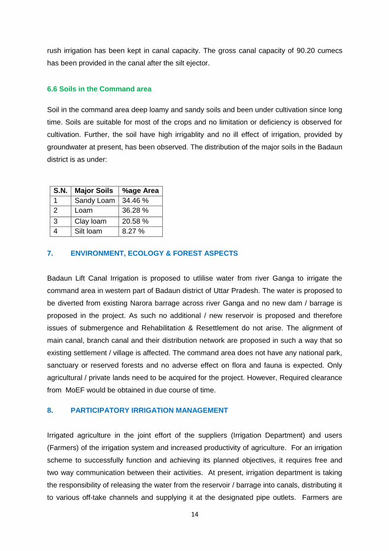
6.6 Soils in the Command area
Soil in the command area deep loamy and sandy soils and been under cultivation since long
time. Soils are suitable for most of the crops and no limitation or deficiency is observed for
cultivation. Further, the soil have high irrigablity and no ill effect of irrigation, provided by
groundwater at present, has been observed. The distribution of the major soils in the Badaun
district is as under:
S.N. Major Soils %age Area
1 Sandy Loam 34.46 %
2 Loam 36.28 %
3 Clay loam 20.58 %
4 Silt loam 8.27 %
7. ENVIRONMENT, ECOLOGY & FOREST ASPECTS
Badaun Lift Canal Irrigation is proposed to utlilise water from river Ganga to irrigate the
command area in western part of Badaun district of Uttar Pradesh. The water is proposed to
be diverted from existing Narora barrage across river Ganga and no new dam / barrage is
proposed in the project. As such no additional / new reservoir is proposed and therefore
issues of submergence and Rehabilitation & Resettlement do not arise. The alignment of
main canal, branch canal and their distribution network are proposed in such a way that so
existing settlement / village is affected. The command area does not have any national park,
sanctuary or reserved forests and no adverse effect on flora and fauna is expected. Only
agricultural / private lands need to be acquired for the project. However, Required clearance
from MoEF would be obtained in due course of time.
8. PARTICIPATORY IRRIGATION MANAGEMENT
Irrigated agriculture in the joint effort of the suppliers (Irrigation Department) and users
(Farmers) of the irrigation system and increased productivity of agriculture. For an irrigation
scheme to successfully function and achieving its planned objectives, it requires free and
two way communication between their activities. At present, irrigation department is taking
the responsibility of releasing the water from the reservoir / barrage into canals, distributing it
to various off-take channels and supplying it at the designated pipe outlets. Farmers are
15
taking the responsibility to distribute the water available at the pipe outlets among
themselves equitably in proportion to the extent of their land holdings. However, due to
some managerial deficiencies and communication gap between the irrigation department
and farmers, the water may not reach many pipe outlets at the tail ends of the distribution
system due to over use and wastage in upper reaches.
In view of the above experience, the Govt. of Uttar Pradesh has enacted an act on
Participatory Irrigation Management (PIM) namely Uttar Pradesh Participatory Irrigation
Management (PIM) Act. 2009 to promote farmers’ participation in irrigation management
and the same was notified and published in Uttar Pradesh Gazette through G.O. No. 1758 /
10-27 Irri. -4-67-(W)/96 T.C. Dated 30th March, 2010.
The act a) envisages creation of WUAs in all irrigation project of the state b) give water
rights to WUAs c) provide functional and administrative autonomy to the WUAs d) makes
irrigation department staff accountable to WUAs e) enables WUAs to resolve conflicts
among themselves f) enables improvement of the irrigation system by the WUAs based on
resources raised by the WUAs on scheme operation h) requires the preparation of an
operation plan and maintenance plan i) contains procedures and guidelines on accounting ,
social accounting, water budgeting, election procedure and other administrations.
This act envisages formation of the following committees at various levels in an irrigation
scheme i.e. a ) Water user association (WUA) at the field channel & minor level b)
Distributory committee at Distributory level c) Branch level committee and d) Project
committee at project level.
9. TRAINING
Uttar Pradesh State Irrigation Department (UPID) came into existence in 1823 and first
irrigation office became functional at Saharanpur. With time, the department has grown up
and handles the primary responsibility of managing the water resources of this vast state.
With rise in the irrigation network, the size as well as the complexities of management issue
of the UPID has increased. The profile of services rendered to farmers / cultivator by the
department has also undergone many changes and officers and staff need to be equipped
with higher skills in performing various functions. All the personnel working in a organization
should be trained to perform the duties carried out by them as per their job profile. At higher
level of hierarchy, it is important to train the officers in handling the administrative and
managerial issues involved. At junior level, the officers and staff should be imparted
16
training to equip them with technical skills required for efficient functioning, management
skills so that they can have better co-ordination with WUAs, NGOs and other stakeholders.
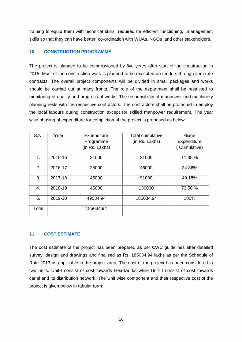
10. CONSTRUCTION PROGRAMME
The project is planned to be commissioned by five years after start of the construction in
2015. Most of the construction work is planned to be executed on tenders through item rate
contracts. The overall project components will be divided in small packages and works
should be carried out at many fronts. The role of the department shall be restricted to
monitoring of quality and progress of works. The responsibility of manpower and machinery
planning rests with the respective contractors. The contractors shall be promoted to employ
the local labours during construction except for skilled manpower requirement. The year
wise phasing of expenditure for completion of the project is proposed as below:
S.N. Year Expenditure
Programme
(in Rs. Lakhs)
Total cumulative
(in Rs. Lakhs)
%age
Expenditure
( Cumulative)
1. 2015-16 21000 21000 11.35 %
2. 2016-17 25000 46000 24.86%
3. 2017-18 45000 91000 49.18%
4. 2018-19 45000 136000 73.50 %
5. 2019-20 49034.94 185034.94 100%
Total 185034.94
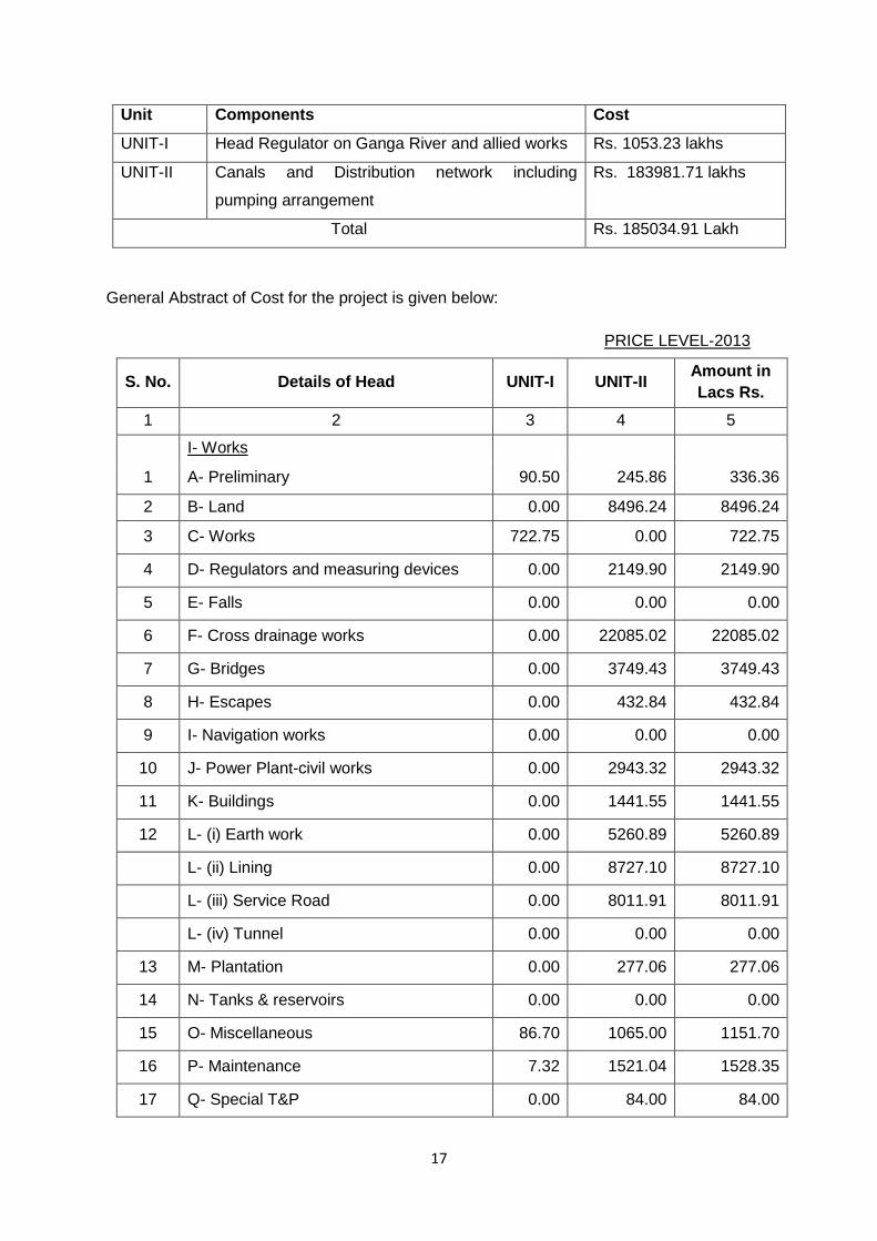
11. COST ESTIMATE
The cost estimate of the project has been prepared as per CWC guidelines after detailed
survey, design and drawings and finalised as Rs. 185034.94 lakhs as per the Schedule of
Rate 2013 as applicable in the project area. The cost of the project has been considered in
two units. Unit-I consist of cost towards Headworks while Unit-II consist of cost towards
canal and its distribution network. The Unit wise component and their respective cost of the
project is given below in tabular form:
17
Unit Components Cost
UNIT-I Head Regulator on Ganga River and allied works Rs. 1053.23 lakhs
UNIT-II Canals and Distribution network including
pumping arrangement
Rs. 183981.71 lakhs
Total Rs. 185034.91 Lakh
General Abstract of Cost for the project is given below:
PRICE LEVEL-2013
S. No. Details of Head UNIT-I UNIT-II Amount in
Lacs Rs.
1 2 3 4 5
I- Works
1 A- Preliminary 90.50 245.86 336.36
2 B- Land 0.00 8496.24 8496.24
3 C- Works 722.75 0.00 722.75
4 D- Regulators and measuring devices 0.00 2149.90 2149.90
5 E- Falls 0.00 0.00 0.00
6 F- Cross drainage works 0.00 22085.02 22085.02
7 G- Bridges 0.00 3749.43 3749.43
8 H- Escapes 0.00 432.84 432.84
9 I- Navigation works 0.00 0.00 0.00
10 J- Power Plant-civil works 0.00 2943.32 2943.32
11 K- Buildings 0.00 1441.55 1441.55
12 L- (i) Earth work 0.00 5260.89 5260.89
L- (ii) Lining 0.00 8727.10 8727.10
L- (iii) Service Road 0.00 8011.91 8011.91
L- (iv) Tunnel 0.00 0.00 0.00
13 M- Plantation 0.00 277.06 277.06
14 N- Tanks & reservoirs 0.00 0.00 0.00
15 O- Miscellaneous 86.70 1065.00 1151.70
16 P- Maintenance 7.32 1521.04 1528.35
17 Q- Special T&P 0.00 84.00 84.00

18
18 R- Communications 0.00 1194.26 1194.26
19 S- Power Plant & Electrical System 0.00 135.44 135.44
20 T- Water Supply Works 0.00 0.00 0.00
21 U- Distributaries Minors & Subminors 0.00 66137.65 66137.65
22 V- Water Courses 0.00 27933.00 27933.00
23 W- Drainage 0.00 0.00 0.00
23 X- Environment and Ecology 22.96 937.00 959.96
24 Y-Losses on Stock 1.83 380.26 382.09
Total : 932.06 163208.75 164140.81
II-Establishment 93.21 15469.11 15562.32
Labour cess 1% 9.32 1632.09 1641.41
Total : 1034.59 180309.95 17203.73
III-Tools and Plant (1% of I-work ) 9.32 1631.87 1641.19
IV-Suspense 0.00 0.00 0.00
V-Receipts and recoveries 0.00 -16.80 -16.80
Total Direct Charges : 1043.91 181925.02 18828.12
Indirect Charges :
Capitalized abatement of land revenue 0.00 424.81 424.81
Audit and Accounts Charges (1% of I-work ) 9.32 1631.87 1641.19
Total Indirect Charges : 9.32 2056.69 2066.01
Grand Total : 1053.23 183981.71 185034.94
Say : 185035.00
12. BENEFIT COST RATIO
Benefit Cost ratio for the project has been computed as 1.88. The computations have been
done as per the pro-forma for B.C. Ratio computation given in “Guidelines for Preparation of
Detailed Project Report of Irrigation and Multipurpose Projects-2010” of CWC/Ministry of
Water Resources, Govt. of India. The B.C Ratio computation is shown below:

19
Benefit Cost Ratio Computations
Badaun Lift Canal Irrigation Project , Uttar Pradesh All values in Rs. Lakh
Estimated cost of the project 185035 lakh CCA (ha)
Cost of Land Development 27933 139665
Sum 212968
Before Irrigation /
Pre Project After Irrigation /
Post Project
A.Gross Receipts
1. Gross value of farm produce 26386.27 88026.3
7
2.Dung receipts ( at 30% of fodder expenditure) 1187.39 2640.80
3. Total (A) Gross receipts (1 & 2) 27573.66 90667.1
7
B. Expenses
1. Expenditure on seeds 2013.80 3502.82
2.Expenditure on manure etc. 2024.28 4997.05
3.Expenditure on hire labour ( human & Bullock) 6024.13 9107.95
4.Fodder expenses 15%of A1 3957.95 10%of A1 8802.64
5.Depreciation on implements 2.7%of A1 712.43 2.7%of A1 2376.72
6.Share and Cash rent 5%of A1 1319.32 3%of A1 2640.79
7.Land Revenue 2%of A1 527.73 2%of A1 1760.53
Total B Expenses(1 to 7)
16579.64 33188.5
0
C. Net value of Produce
1.Total Gross receipts 27573.66 90667.17
2.Minus total expenses 16579.64 33188.50
3.Net value of produce 10994.02 57478.67
D. Annual Agricultural Benefits
1.Net value after Irrigation 57478.67
2.Net value before Irrigation 10994.02
Net Annual Benefits 46484.66
G. Annual Cost
1. Interest on capital @10% 21296.80
2.Depriciation of the project @1% of cost of project 1850.35
3. Annual Operation & Maintenance charges @ Rs 1175 / ha of CCA 1641.06
4.Maintenance of Headworks @ 1% of it’s cost
5.Depreciation of Pumping system @ 8.33 % 3.332
6. Depreciation of Raising mains @ 3.33% 0.333
7.Power Charges 2884
8. Total (G) Annual Cost ( 1 to 7) 24788.21
Benefit Cost Ratio : Annual Benefit / Annual Cost
1.88

20
INDEX FOR DPR
Sl. No. Volume No. Description
1. Volume-I Report
2. Volume-II A Hydrology (Water Availability)
3. Volume-II B Hydrology (Design Flood & Sedimentation)
4. Volume-III A Cost Estimate (Main & Branch canals)
5. Volume-III B Cost Estimate (U-Distributaries & Minors)
6. Volume-IV Drawing