Executing UML State Machines - CiteSeer
22
See discussions, stats, and author profiles for this publication at: https://www.researchgate.net/publication/250390828 Executing UML State Machines Article CITATIONS 11 READS 36 2 authors, including: Dirk Seifert Microsoft 16 PUBLICATIONS 194 CITATIONS SEE PROFILE All content following this page was uploaded by Thomas Santen on 19 December 2013. The user has requested enhancement of the downloaded file.
Transcript of Executing UML State Machines - CiteSeer

See discussions, stats, and author profiles for this publication at: https://www.researchgate.net/publication/250390828
Executing UML State Machines
Article
CITATIONS
11READS
36
2 authors, including:
Dirk Seifert
Microsoft
16 PUBLICATIONS 194 CITATIONS
SEE PROFILE
All content following this page was uploaded by Thomas Santen on 19 December 2013.
The user has requested enhancement of the downloaded file.

Executing UML State Machines
Bericht-Nr. 2006-4
Thomas Santen Dirk Seifert
santen,[email protected]
Marz 2006
ISSN 1436-9915

Executing UML State Machines
Thomas Santen Dirk SeifertTechnische Universitat Berlin, SoftwaretechnikSekr. FR 5-6, Franklinstr. 28/29, 10587 Berlin
{santen,seifert}@cs.tu-berlin.de
Abstract
We present a formal operational semantics for UML state machines. This semanticsis implemented in Teager, a tool suite supporting test automation. This report focuseson defining the way events are processed and firing transitions are determined and ex-ecuted. Furthermore the UML semantics provides variation points to allow for domainspecific specializations. We clearly identify those variation points and thereby make theparameters of the semantics explicit.
1 Introduction
The Unified Modeling Language [UML04] nowadays is the de facto standard for modelingobject-oriented systems. The language comprises various types of models describing thesystem structure or the behavior of components. Generally speaking the UML is a semi-formal modeling language with a precisely defined syntax and static semantics. Thedynamic semantics, however, is defined only informally.
In the UML, class diagrams specify the general structure of a system. Additionally eachclass has an optional state machine associated to it, which describes the discrete behavior(behavioral state machine) or the usage protocol (protocol state machine) of that class.In the following we interpret state machines as behavioral state machines.
The formalism of state machines is a variant of Statecharts [Har87, HN96, PS91, HG97]whose semantics has been adapted to the special requirements of object-oriented systemsin general and the UML in particular. The formalism is based on finite state-transitionsystems and the basic idea is that of state decomposition. As a consequence of integratingthem with the object-oriented paradigm, state machines have many extensions caused byfeatures to model the communication between objects. These are, for example, severaldifferent types of events modeling synchronous or asynchronous message processing, tim-ing and other properties of object communication. As another consequence, the behaviorof state machines, in particular the way events are processed and firing transitions aredetermined, also differs from the behavior of classical Statecharts.
In this report, we concentrate on models describing the discrete behavior of state ma-chines, that means, on the way they process events and determine firing transitions. Wedisregard the complexity added by different types of messages and the data they maycarry. We particularly focus on the interesting conceptual issues of non-determinism.
1
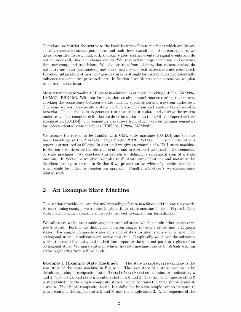
Therefore, we restrict the syntax to the basic features of state machines which are hierar-chically structured states, parallelism and multi-level transitions. As a consequence, wedo not consider history, final, fork and join states, restrict events to signal events and donot consider call, time and change events. We treat neither object creation and destruc-tion, nor compound transitions. We also abstract from all data, that means, actions donot carry any data (parameters) and entry, activity and exit actions are not considered.However, integrating of most of these features is straightforward or does not essentiallyinfluence the semantics presented here. In Section 6 we discuss some extensions we planto address in the future.
Most attempts to formalize UML state machines aim at model checking [LP99a, LMM99a,LMM99b, BBK+04]. With our formalization we aim at conformance testing, that means,checking the consistency between a state machine specification and a system under test.Therefore we wish to execute a state machine specification and analyze the observablebehavior. This is the basis to generate test cases that stimulate and observe the systemunder test. The semantics definition we describe conforms to the UML 2.0 Superstructurespecification [UML04]. Our semantics also draws from other work on defining semanticsfor object-oriented state machines [BBK+04, LP99a, LMM99b].
We assume the reader to be familiar with UML state machines [UML04] and to havebasic knowledge of the Z notation [Z00, Spi92, PST91, WD96]. The remainder of thisreport is structured as follows. In Section 2 we give an example of a UML state machine.In Section 3 we describe the abstract syntax and in Section 4 we describe the semanticsof state machines. We conclude this section by defining a semantical step of a statemachine. In Section 5 we give examples to illustrate our definitions and motivate thedecisions leading to them. In Section 6 we present an overview of possible extensionswhich could be added to broaden our approach. Finally, in Section 7, we discuss somerelated work.
2 An Example State Machine
This section provides an intuitive understanding of state machines and the way they work.As our running example we use the simple fictitious state machine shown in Figure 1. Thisstate machine which contains all aspects we need to explain our formalization.
We call states which are atomic simple states and states which contain other states com-posite states. Further we distinguish between simple composite states and orthogonalstates. For simple composite states only one of its substates is active at a time. Fororthogonal states all substates are active at a time. Graphically we depict the substateswithin the enclosing state, and dashed lines separate the different parts or regions of anorthogonal state. We mark states in which the state machine resides by default with anarrow originating from a filled circle.
Example 1 (Example State Machine). The state Example State Machine is theroot state of the state machine in Figure 1. The root state of a state machine is bydefinition a simple composite state. Example State Machine contains two substates, Aand B. The orthogonal state A is subdivided into C and D. The simple composite state Cis subdivided into the simple composite state E, which contains the three simple states H,I and K. The simple composite state D is subdivided into the simple composite state F,which contains the simple states L and M, and the simple state G. A consequence of the
2
F
��
��
��
��
�
C
I K
H
AD
B
M
L
E
G
t1 t2
Example State Machine
t4
t3
t6 t7
t5
t8
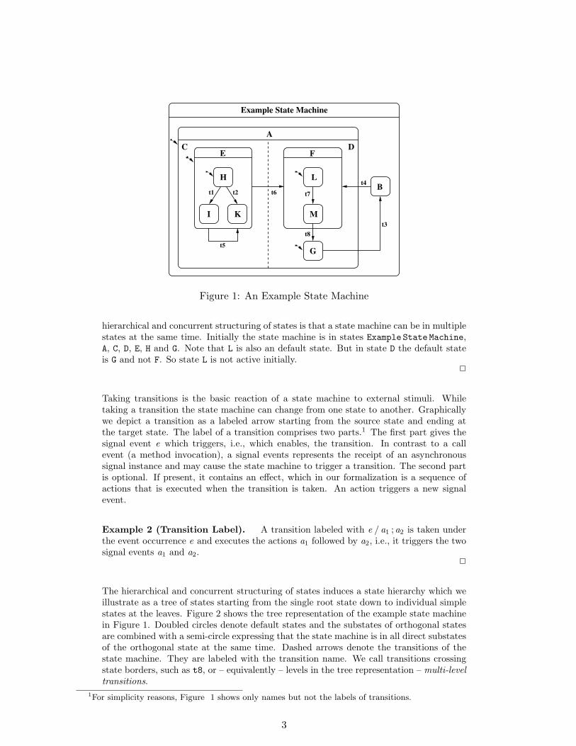
Figure 1: An Example State Machine
hierarchical and concurrent structuring of states is that a state machine can be in multiplestates at the same time. Initially the state machine is in states Example State Machine,A, C, D, E, H and G. Note that L is also an default state. But in state D the default stateis G and not F. So state L is not active initially.
2
Taking transitions is the basic reaction of a state machine to external stimuli. Whiletaking a transition the state machine can change from one state to another. Graphicallywe depict a transition as a labeled arrow starting from the source state and ending atthe target state. The label of a transition comprises two parts.1 The first part gives thesignal event e which triggers, i.e., which enables, the transition. In contrast to a callevent (a method invocation), a signal events represents the receipt of an asynchronoussignal instance and may cause the state machine to trigger a transition. The second partis optional. If present, it contains an effect, which in our formalization is a sequence ofactions that is executed when the transition is taken. An action triggers a new signalevent.
Example 2 (Transition Label). A transition labeled with e / a1 ;a2 is taken underthe event occurrence e and executes the actions a1 followed by a2, i.e., it triggers the twosignal events a1 and a2.
2
The hierarchical and concurrent structuring of states induces a state hierarchy which weillustrate as a tree of states starting from the single root state down to individual simplestates at the leaves. Figure 2 shows the tree representation of the example state machinein Figure 1. Doubled circles denote default states and the substates of orthogonal statesare combined with a semi-circle expressing that the state machine is in all direct substatesof the orthogonal state at the same time. Dashed arrows denote the transitions of thestate machine. They are labeled with the transition name. We call transitions crossingstate borders, such as t8, or – equivalently – levels in the tree representation – multi-leveltransitions.
1For simplicity reasons, Figure 1 shows only names but not the labels of transitions.
3

BA
Example State Machine
C D
F G
L MKI
E
Ht1
t2
t3
t4
t5t6
t7
t8
Figure 2: Tree Representation
Taking a transition comprises leaving the source state and entering the target state afterexecuting all actions. Note that leaving one orthogonal part of a state due to a multi-leveltransition comprises leaving all orthogonal parts of that state, and that entering one partof an orthogonal state directly causes the state machine to enter all default states in theremaining parts.
Example 3 (Firing a Transition). Taking transition t1 in Figure 1 means to leavestate H and to enter state I whereas taking transition t3 means to leave A and all of itsactive substates and to enter state B. On the other hand taking transition t4 causes thestate machine to leave state B and to enter the states A and D, F and L in the right-handside orthogonal part, and C, E and H in the left-hand side orthogonal part.
2
In the following we present a formalization for a subset of UML state machines. Thissubset is suitable for basic state machine execution and therefore for generating test casesfrom state machine specifications. In Section 3 we present the abstract syntax we use forstate machines and in Section 4 we present a formal operational semantics.
3 Abstract Syntax
A state machine SM == ((S ,H ),E ,T ,D) is a structure consisting of four components.(S ,H ) denotes a state hierarchy, E denotes a finite set of events, T denotes a finite setof transitions, and D ⊆ S denotes the set of default states. The state hierarchy (S ,H )consists of a finite set S of states and a substate relation H ⊆ S × S .
Definition 1 (Type). Given a state machine SM == ((S ,H ),E ,T ,D), the functiontype : S → {simple, simple composite, orthogonal} determines the type of each states ∈ S in the state hierarchy H .
2
The UML standard [UML04] uses three attributes to specify the type of a state. Theattribute isSimple stores whether a state is a simple state, the attribute isCompositestores whether a state is decomposed into substates and the attribute isOrthogonal stores
4
whether a state contains orthogonal substates. These attributes correspond to Definition 1as follows:
type(s) =
simple if s.isSimple,
simple composite if ¬ s.isSimple ∧ s.isComposite ∧ ¬ s.isOrthogonal ,orthogonal if ¬ s.isSimple ∧ s.isComposite ∧ s.isOrthogonal .
Using the typing function type(s) avoids unnecessary redundancy, because all combina-tions of attribute values that do not correspond to a type are not allowed.
We call a state s a composite state if type(s) is either simple composite or orthogonal.Additionally we require that S contains a unique and distinguished root state, which isthe only state which is not a substate of another state, which is a simple composite state,which is neither the source nor the target of a transition, and which is a default state.
Constraint 2 (Root State). Given a state machine SM == ((S ,H ),E ,T ,D), thereexists a distinguished state r ∈ S which has no parent. We call this state the root stateof SM and refer to it with root .
type(root) = simple composite (1)∀ t : T • root 6= source(t) ∧ root 6= target(t) (2)root ∈ D (3)
where root == µ s : S • s /∈ ranH .2
To describe the structural relations between states we define three functions. The functionsubstates : S→F S yields the finite set of all immediate substates of a state. The functionssubstates+ → F S and substates∗ → F S yield the finite set of all transitive substates andthe finite set of all transitive-reflexive substates, respectively.
Definition 3 (Substates). Given a state machine SM == ((S ,H ),E ,T ,D), thefinite sets of substates are defined as follows.
substates(s) == {s ′ : S | s 7→ s ′ ∈ H } (1)
substates+(s) == {s ′ : S | s 7→ s ′ ∈ H +} (2)
substates∗(s) == {s} ∪ substates+(s) (3)
where H + denotes the transitive closure of H .2
If s2 ∈ substates∗(s1), we say that s1 is an ancestor of s2 and that s2 is a descendant ofs1. If s2 ∈ substates+(s1), we say that s1 is a strict ancestor of s2 and that s2 is a strictdescendant of s1. If s1 is either an ancestor or a descendant of s2, we say that s1 ands2 are ancestrally related [Har87]. Note that for a state s both applies: s is an ancestorand a descendant of itself. It also applies that the root state is an ancestor of every states ∈ S and that every state, except the root state, has a single parent. Thus, the hierarchyrelation arranges the states of a state machine in a tree.
5

Constraint 4 (Hierarchy Relation). Given a state machineSM == ((S ,H ),E ,T ,D), the state hierarchy must form a finite tree rooted at root andwith the simple states of S as its leafs.
∃1 r ∈ S • r /∈ ranH (1)∀ s : S \ {root} • ∃1 s ′ ∈ S • s ′ 7→ s ∈ H (2)
2
Definition 5 (Container). Given a state machine SM == ((S ,H ),E ,T ,D), the par-tial function container : S 7→ S yields the parent state of each state s ∈ S \ {root}. Theparent state exists and is unique (cf. Constraint 4).
container(s) == µ s ′ : S | s ′ 7→ s ∈ H (1)
2
Constraint 6 (States). Given a state machine SM == ((S ,H ),E ,T ,D), for everystate s ∈ S the following constraints must hold.
type(s) = simple ⇒ substates(s) = ∅ (1)type(s) = orthogonal ⇒ #substates(s) ≥ 2 ∧
∀ s ′ : substates(s) • type(s ′) = simple composite ∧substates(s) ⊆ D
(2)
type(s) = simple composite ⇒ #substates(s) ≥ 1 ∧∃1 s ′ : substates(s) • s ′ ∈ D
(3)
2
Constraint 6.1 requires that a simple state has no direct substate. Constraint 6.2 requiresthat for an orthogonal state the number of substates must be greater than or equal totwo, that all substates of an orthogonal state must be of type simple composite, and thatall direct substates are default states. Thus we yield a unique representation for statemachines. Constraint 6.3 requires that an simple composite state has at least one directsubstate and that exactly one direct substate is a default state.
A transition t in T ⊆ S × E × seqE × S consists of four parts. To access these partswe define four projections. The projection source : T → S yields the source state of atransition t .1. The projection trigger : T → E yields the trigger of a transition t .2. Theprojection effect : T→seqE yields the effect of a transition t .3, i.e., a sequence of actions,and finally the projection target : T → S yields the target state of a transition t .4.
Constraint 7 (Transition). Given a state machine SM == ((S ,H ),E ,T ,D), forevery transition t ∈ T the following constraints must hold.
type(source(t)) = simple composite⇒ type(container(source(t))) 6= orthogonal (1)type(target(t)) = simple composite⇒ type(container(target(t))) 6= orthogonal (2)
2
6

The Constraints 7.1 and 7.2 require that neither the source state nor the target state of atransition is a direct substate of an orthogonal state. Direct substates of orthogonal statesare only used as containers, i.e., for structuring and naming different parts of orthogonalstates. In addition, note that it is impossible to start or to end an arrow of a transitionat only one part of an orthogonal state. In the UML standard a simple composite statecontains one (so called) region and an orthogonal state is decomposed into two or moreorthogonal regions. Each region has a set of mutually exclusive disjoint substates and aset of transitions [UML04]. In our semantics definitions we do not need the meaning ofregions, instead we allow, as we described above, only simple composite states as directsubstates of orthogonal states. Also remember that the root state of a state machineneither is the source nor the target state of any transition (cf. Constraint 2).
4 Semantics
This section states an operational semantics of state machines. First we define a semanticalstate of a state machine. Then we characterize how to identify a set of transitions whichfire within a step, and finally, we define a semantical step of a state machine in moredetail.
State machines communicate by sending events to each other. While executing, a statemachine generates events which will be sent to other objects, and it receives events gener-ated by other objects. Among the set of evens E we distinguish a set of events ESM whichcontains all events that can possibly be sent to the state machine. The events a statemachine receives are stored for further processing within the state machine. The UMLstandard does not specify in detail the way of storing and dispatching events. Insteadthe user has to define a management policy within a so-called semantic variation point :semantic variation points explicitly identify the areas where the semantics are intention-ally under specified to provide leeway for domain-specific refinements of the general UMLsemantics (e.g., by using stereotypes and profiles) [UML04].
Concerning the management policy the following abstract description of event processingis given in the standard: Events are often generated as a result of some action eitherwithin the system or in the environment surrounding the system. Upon their occurrence,events are placed into the input pool of the object where they occurred (. . . ). An event isdispatched when it is taken from the input pool and either directly causes the occurrence ofa behavior or are delivered to the classifier behavior of the receiving object for processing.At this point, the event is considered consumed and referred to as the current event.A consumed event is no longer available for processing. (. . . ) Event occurrences aredetected, dispatched, and then processed by the state machine, one at a time. The orderof dequeuing is not defined, leaving open the possibility of modeling different priority-based schemes [UML04].
In most practical applications a priorized queue is used for storing events. We stay a littlemore abstract and rely on an abstract data type Q to describe the event managementpolicy. This data type meets all requirements of the UML standard and does not constrainpossible realizations. The function enqueue : Q× seqESM →Q adds a sequence of eventsinto a queue. The function dequeue : Q→ ESM ×Q dispatches an event from the queue,yielding the current event and the input queue with the current event removed. Theboolean function empty : Q → B describes whether a given queue is empty or not.
7
Definition 8 (Queue Operations). Given a state machine SM == ((S ,H ),E ,T ,D),the function enqueue and the function dequeue are defined as follows.
enqueue(Q , es) == Q ′, where Q ′ == Q ⊕ es (1)dequeue(Q) == (e,Q ′), where Q ′ == Q e (2)
2
Defining the two functions ⊕ and instantiates a further semantic variation point andthus specifies a concrete queue data type.
Definition 9 (Active State Configuration). Given a state machine SM ==((S ,H ),E ,T ,D), an active state configuration or configuration C : F S of a state machineis the set of all active states at a time, i.e., the set of all states in which the state machineresides at that point in time. It must satisfy the following conditions.
root ∈ C (1)∀ s : C | type(s) = simple composite • ∃1 s ′ : substates(s) • s ′ ∈ C (2)∀ s : C | type(s) = orthogonal • ∀ s ′ : substates(s) • s ′ ∈ C (3)
The initial configuration must additionally satisfy the following constraint.
C ⊆ D (4)
2
Constraint 9.1 requires root to be a member of every configuration, which is natural.Constraint 9.2 requires that exactly one direct substate of an active simple compositestate is active. Constraint 9.3 requires that all direct substates of an active orthogonalstate are active. This explains why simple composite states are also referred to as xorstates and why orthogonal states are also referred to as and states. If the type of astate s is simple composite, substates(s) is an exclusive or-decomposition of s, i.e., thestate machine is in exactly one of its immediate substates at a time. If the type of astate s is orthogonal, substates(s) is an and-decomposition of s, i.e., the state machinesimultaneously is in all of its immediate substates at a time. Additionally Constraint 9.4requires for the initial configuration that every state also is a default state. Note thatthe initial configuration is different from the set of all default states. The reason is thata member of the set of default states D becomes active if its container becomes active.However, not every container is active initially.
On the basis of a configuration we can also form a tree structure starting at the rootstate. This structure (C ,C /H ) is a restriction of the state hierarchy of the state machine(S ,H ), and it is well-formed due to Constraint 6. Now we can characterize the status ofa state machine by an active state configuration and an event queue.
Definition 10 (Status). Given a configuration C : F S and an event queue Q : Q ,each status of a state machine consists of a pair [[C ,Q ]]. The initial status of a statemachine consists of the initial configuration and an empty queue.
2
8

4.1 Event Processing – The Run-To-Completion Step
The execution semantics of state machines is defined in the UML standard in termsof a hypothetical machine. This machine consists of three key components. The firstcomponent is an event queue which holds incoming events2 until they are dispatched.The second component is an event dispatch mechanism for selecting and dispatchingevents. And the third component is an event processor which executes the state machinein a so-called run-to-completion step: The semantics of event occurrence processing isbased on the run-to-completion assumption, interpreted as run-to-completion processing.Run-to-completion processing means that an event occurrence can only be taken from thepool and dispatched if the processing of the previous current occurrence is fully completed[UML04].
Thus events are detected, dispatched and processed one at a time. Within a run-to-completion step the state machine moves from one status to the next status. When anevent is dispatched, one or more transitions may become enabled for firing. If no transitionis enabled, the event occurrence is discarded and the run-to-completion step is completed– which is also referred to as stuttering.
Definition 11 (Enabled Transition). Given a state machine SM ==((S ,H ),E ,T ,D) and a status [[C ,Q ]], the boolean function enabled : T ×ESM ×F S →Bsignifies whether a transition t is enabled w.r.t. an event e and a configuration C . A tran-sition is said to be enabled if and only if the source state is in the current configurationand the trigger is equal to the current event.
enabled(t , e,C ) ==
{true if source(t) ∈ C ∧ trigger(t) = efalse otherwise
(1)
where (e,Q ′) == dequeue(Q).2
If several transitions are enabled they may be in conflict with each other. Some conflictscan be resolved based on a transition priority. This priority is defined by the relativeposition of the source states of the transitions in the state hierarchy. In a state machine, atransition originating from a substate has priority over a conflicting transition originatingfrom any of the containing states of that substate. The transition selection algorithmdetermines which of the enabled transitions actually fires. In Figure 1, for example,transition t1 and t2 are in conflict; only one can fire at a time to reach a new well-formedconfiguration.
Definition 12 (Consistent and Conflicting Transitions). Given a state machineSM == ((S ,H ),E ,T ,D), transitions t1, t2 ∈ T are called consistent, denoted t1 ‖ t2, ifthey do not have a common state to be left. Otherwise, these transition are in conflict,denoted t1 ∦ t2.
t1 ‖ t2 ⇔ exits(t1) ∩ exits(t2) = ∅ (1)
2
2In the object oriented terminology it is better to speak of event occurrences since we observe the occurrenceof an event instance. Anyway we use the term event for simplicity reasons.
9

To allow transitions to cross levels in the state hierarchy, so-called inter-level transitions,we take the scope of a transition into account. Taking transition t3 in Figure 1 does notonly cause the machine to leave state G but also the entire state A. Therefore the scopeExample State Machine of transition t3 must indicate the subtree of the state hierarchywhich is affected when firing a transition. The scope is determined from the source andthe target state of a transition.
Definition 13 (Scope of a Transition). Given a state machine SM ==((S ,H ),E ,T ,D), the function scope : T → S yields the scope (or least common an-cestor) of the source state and the target state of a transition. It is the (uniquely defined)smallest composite state which contains the source state and the target state.
scope(t) == µ s : S |source(t) ∈ substates+(s) ∧ target(t) ∈ substates+(s)∧ (1)
(∀ s ′ : S | s ′ ∈ substates+(s) • (2)
¬(source(t) ∈ substates+(s ′) ∧ target(t) ∈ substates+(s ′))) (3)
2
Two states are orthogonal if they are not ancestrally related and their scope is an orthog-onal state. For every set R of states, we say that the set R is consistent if and only ifevery two states s1, s2 ∈ R either are ancestrally related or orthogonal. On the basis ofthe scope we define the main source and the main target of transition t . It follows fromDefinition 4 and Definition 13 that the main source and the main target of a transitionexist and are unique.
Definition 14 (Main Source and Main Target). Given a state machine SM ==((S ,H ),E ,T ,D), the main source and the main target are defined as follows.
mainSource(t) ==
µ s : substates(scope(t)) | source(t) ∈ substates∗(s)
if type(scope(t)) = simple composite
scope(t)if type(scope(t)) = orthogonal
(1)
mainTarget(t) ==
µ s : substates(scope(t)) | target(t) ∈ substates∗(s)
if type(scope(t)) = simple composite
scope(t)if type(scope(t)) = orthogonal
(2)
2
Based on the main source and the main target of a transition we define the set of stateswhich will be left when firing this transition as follows.
Definition 15 (States to be Left). Given a state machine SM == ((S ,H ),E ,T ,D)and a status [[C ,Q ]], the function exits : T → F S yields the set of states which will beleft when taking a transition t ∈ T .
exits(t) == substates∗(mainSource(t)) ∩ C (1)
2
10

As previously mentioned some conflicts can be resolved by priorizing transitions. Thepriority is based on the relative position of the source states in the state hierarchy. Atransition originating from a substate has priority over a conflicting transition originatingfrom any of its containing states.
Definition 16 (Priority of Transitions). Given a state machine SM ==((S ,H ),E ,T ,D), the priority relation ≺: T × T relates two transitions. A transitiont2 ∈ T has priority over a transition t1 ∈ T , if and only if t1 ≺ t2.
t1 ≺ t2 ⇔ source(t2) ∈ substates+(source(t1))
2
The reflexive closure of the priority relation is a partial order.
With this priority scheme we can resolve some of the possible conflicts between enabledtransitions but not all of them. For example in Figure 1, both transitions t1 and t2 leavestate H but none of them has priority over the other. If both are enabled, the machinemust – nondeterministically – select one transition for firing.
In general, a transition selection algorithm selects a set T‖ ⊆ T of transitions for firing.For this set – the firing transition set – the following constraints must hold.
Constraint 17 (Firing Transition Set). Given a state machine SM ==((S ,H ),E ,T ,D) and a status [[C ,Q ]], the following constraints must hold for every firingtransition set T‖.
∀ t : T‖ • enabled(t , e,C ) (1)∀ t1, t2 : T‖ | t1 6= t2 • t1 ‖ t2 (2)¬ (∃ t ′ : T \ T‖ | enabled(t ′, e,C ) • ∀ t : T‖ • t ‖ t ′ ∨ t ≺ t ′) (3)
where (e,Q ′) == dequeue(Q)2
Constraint 17.1 requires that all transitions in T‖ are enabled, which means that thetrigger of each transition is equal to the current event. Constraint 17.2 requires thatall transitions in T‖ are mutually consistent. Constraint 17.3 requires that there is notransition outside T‖ which is consistent with all transitions in T‖ or with priority over atransition in T‖. Precisely, with t ‖ t ′ we ensure that the set contains the maximal numberof consistent transitions. With t ≺ t ′ we ensure that we select transitions with the highestpriority. If there is more than one set fulfilling Constraint 17 the state machine is saidto be non-deterministic, because we are free to – arbitrarily – choose one set. Defining aspecific selection strategy instantiates a further semantic variation point and thus definesa concrete transition selection algorithm.
Definition 18 (States to be Entered). Given a state machine SM ==((S ,H ),E ,T ,D), the function enters : S × S → F S applied to the main target andto the target of a transition t ∈ T yields the set of states which will be entered when
11

firing the transition.
enters(s, target) ==
{s}if type(s) = simple
{s} ∪⋃
s′∈substates(s)
enters(s ′, target)
if type(s) = orthogonal
{s} ∪ enters(s ′′, target)if type(s) = simple composite
where
s ′′ == µ s ′′′ : substates(s) | target ∈ substates∗(s ′′′) ∨(s ′′′ ∈ D ∧ target /∈ substates+(s))
2
Starting from the main target of a transition we calculate the set of states to be entered.If the given state s is a simple state only this state is entered. If the given state s isan orthogonal state all substates are entered since all substates also become active if thecontainer becomes active (cf. Constraint 6.2). If the given state is a simple composite statewe distinguish two alternatives. Either we enter the direct substate s ′′′ which containsthe target state – target ∈ substates∗(s ′′′). Then we are on the way down from the maintarget to the target state. Or we enter the default state s ′′′ if the target state is not asubstate of the current state – s ′′′ ∈ D ∧ target /∈ substates+(s). The latter case alsocovers the explicit entering of orthogonal parts. In that case we are on the way down andhave already reached the target state, or we are on the way down and have to enter anorthogonal part which the transition does not enter explicitly.
4.2 Semantical Step
A semantical step is the transition from one status to the next status and comprisesexecuting all transitions in the firing transition set. This contains determining the setof firing transitions w.r.t. the current event, followed by firing each transition. Firing atransition t consists of leaving all states in exits(t), executing all actions of effect(t) andentering all states in enters(t). The next status comprises the resulting configuration andthe resulting queue which is build from dequeuing the current event, enqueuing generatedevents and events received from the environment.
For the definition of a semantical step we further partition the state machine’s event setESM ⊆ E into two disjoint sets: the set of public events Epub
SM contains all events whichthe environment can generate; the set of private events Eprv
SM contains all events whichonly a state machine instance itself can generate.
Finally we define a semantical step [[C ,Q ]]Ein ,Eout−−−−−→ [[C ′,Q ′ ]] whereas we distinguish two
situations. First, if the current queue is empty, the state machine is stuttering and thusdoes not change the current configuration. Second, if we can dispatch the current event,the state machine moves from the current status to the next status as described above.
12

Definition 19 (State Machine Step). Given a state machine SM ==((S ,H ),E ,T ,D), a status [[C ,Q ]] and a sequence of incoming events seqEin (whereEin ⊆ Epub
SM ) which were generated by the environment during the step. The followingrules define the status transition relation −→: status × seqEpub
SM × seq (E \ESM )× status.
empty(Q)Q ′ = enqueue(Q ,Ein)
[[C ,Q ]]Ein ,∅−−−−−→ [[C ,Q ′ ]]
¬ empty(Q)(e,Q ′′) = dequeue(Q)
T‖ ⊆ T ∧ T‖ � Constraint 17C ′ = (C \ exits(T‖)) ∪ enters(T‖)
Eint = a/Xint ∧Xint ∈ perm({t : T‖ • effect(t) � ESM })
Eout = a/Yout ∧Yout ∈ perm({t : T‖ • effect(t)) � (E \ ESM )}
Q ′ = enqueue(Q ′′,Einta Ein)
[[C ,Q ]]Ein ,Eout−−−−−→ [[C ′,Q ′ ]]
whereas we denote the sequence of outgoing events by Eout : seq (E \ ESM ) and thesequence of all internal events by Eint : seqESM .
2
Note that the set of outgoing events Eout will be sent to the environment, precisely to theappropriate objects. The function perm : F seqE → F seq seqE yields for a set of eventsequences the set of all permutations of these sequences. The function a/ : seq seqE →seqE flattens an event sequence (distributed concatenation).
In this definition we have two further semantic variation points. The first semantic vari-ation point leaves open the order of the transitions which will fire during the step. Thetransition selection algorithm only selects a set of transitions for firing (cf. Section 5).The second semantic variation point leaves open how to enqueue events generated duringthe step by the state machine instance and events received from the environment. In ourformalization we choose to treat a step to be atomic and enqueue events received fromthe environment at the end of the queue. Different solutions are possible.
5 Discussion
In the following we present some annotations and examples to illustrate our definitions.With these additional explanations we aim to help the reader to understand the particularformulation of our definitions.
5.1 Firing Transitions
When firing a transition we need to determine which states will be left and which stateswill be entered. For flat transition systems, i.e., for transition systems without statedecomposition, this is straightforward: the source state of the transition will be left andthe target state will be entered. But in the presence of hierarchically structured states,parallelism and transitions crossing state borders, things become more complicated.
13

The solution is to start at the source state of the transition and to move upwards in thestate hierarchy, i.e., in the tree representation, and search for the least state (the firstwhen moving upwards) which contains the target state of the transition. We call thisstate the scope of the transition. The scope gives us the root state of the sub-tree which isaffected by the transition. All states which will be left and all states which will be enteredwhen firing the transitions are below this state.
Example 4. In Figure 3 the least common ancestor of both transition t1 and transitiont2 is state E. For example, in the right-hand part of the figure, starting at H, the firstcomposite state containing source and target of transition t1 is E. For transition t6,starting at state E the least composite state containing both source and target is A sincewe leave state A when taking transition t6 and re-enter state A (see below).
2
If we want to determine the set of states which will be left when firing a transition we couldintersect the current configuration with the set of all states of the transition’s scope. Butif we have a closer look at transition t1 and t6 we notice that this procedure is not correct.For example, for transition t1, there is no reason to leave the scope itself. Leaving stateE and reentering state E would indeed result in a well-formed active state configurationbut this would unnecessarily leave and enter state E. This is a problem if actions need tobe executed upon leaving or entering states.
When firing transition t6 the left orthogonal part of A will be left and the right orthogonalpart will be entered. But what happens to the left part or to a possible third orthogonalpart? Will the former also be entered? Will the latter be left? In this case, we mustleave the complete orthogonal state A and re-enter A: transition t6 enters the orthogonalpart D explicitly and all other orthogonal parts implicitly. This distinction leads to thedefinition of main source and main target of a transition. They depend on the type ofthe scope. For simple composite states we use direct substates to define main source andmain target and for orthogonal states we use the scope itself (cf. Definition 14).
To the best of our knowledge the only situation in which the least common ancestor is anorthogonal state arises if a transition leaves an orthogonal part and reenters an orthogonalpart of the same orthogonal state.
Example 5. Since E is a composite state, the main source of transition t2 is state Hand the main target is K. There is no reason to leave or to enter another state. However,A is an orthogonal state, and the main source and the main target of transition t6 are A.
2
For determining the set of states to be left when firing a transition t we intersect theactive state configuration with the set of substates of the main source of t .
Example 6. Given an active state configuration C ={ExampleStateMachine, A, C, D, E, G, H}, when firing transition t1 we leavestates {H}, since {ExampleStateMachine, A, C, D, E, G, H} ∩ {H} = {H}, where{H} = substates∗(H). When firing transition t6 we leave states {A, C, D, E, G, H}, since{ExampleStateMachine, A, C, D, E, G, H} ∩ {A, C, D, E, F, G, H, I, K, L, M} = {A, C, D, E, G, H},where {A, C, D, E, F, G, H, I, K, L, M} = substates∗(A) and mainSource(t6) = A.
2
14

F
��
��
��
��
�
C
I K
H
AD
B
M
L
E
G
t1 t2
Example State Machine
t4
t3
t6 t7
t5
t8
BA
Example State Machine
C D
F G
L MKI
E
Ht1
t2
t3
t4
t5t6
t7
t8
Figure 3: Example State Machine from Figure 1.
Determining the set of states to be entered when firing a transition is a little bit morecomplicated. The definition of enters is intuitive for simple and orthogonal states (cf.Definition 18). For simple composite states we give some explanations in the following.
The definition is complicated by the fact that simple composite states can be substates oforthogonal states. It is possible to have the target of a transition within one orthogonalpart of a state and so the simple composite states of the other parts are not directlyaffected. Consider firing transition t4. The target of transition t4 is state F. Afterleaving all corresponding states we have to enter all appropriate states starting at themain target A. Starting at state A, we enter D, F, L in the right sub-tree and C, E, H in theleft sub-tree. Definition 18 says:
enters(s, target) ==
{s}if type(s) = simple
{s} ∪⋃
s′∈substates(s)
enters(s ′, target)
if type(s) = orthogonal
{s} ∪ enters(s ′′, target)if type(s) = simple composite
where
s ′′ == µ s ′′′ : substates(s) | target ∈ substates∗(s ′′′) ∨(s ′′′ ∈ D ∧ target /∈ substates+(s))
In state D – which is a simple composite state – we enter F since the target F is in thesubstates of D (first alternative). We do not enter G. Indeed G is an default state but thetarget state is in the substates of D (second alternative). With substates∗(s ′) we selectthis substate to enter which leads us to the target state, with substates+(s) we ensurethat initial states are entered only if we are not on the way down to the target state.This happens in exactly two situations. The first situation arises if we reach the targetstate and need to enter the appropriate states below the target. When entering F thereis no substate from which we can reach the target state (first alternative), so we choosethe initial substate since the target also is not a substate of F. The second situation is
15

that we need to enter a further orthogonal part like for state C. Here we enter in eachcase the initial state E and H (second alternative). Note, in the first alternative we havea predicate over a concrete substates, in the second alternative we have a predicate overall substates. This is needed to precisely distinguish between the way down to the targetstate and entering all initial states.
5.2 Firing Transition Sets
When determining the sets of firing transitions we search for all largest sets of transitionsfulfilling Constraint 17. Therefore we use co-induction. Starting with the set of all enabledtransitions we check whether the required constraints hold. If this is the case we stop andthe resulting set contains only this set of all enabled transitions. If this is not the casewe remove an arbitrary transition and check the constraints again. If the constraints stilldo not hold we choose another transition. If we have removed every transition once, thenwe repeat this procedure for two (three, four, . . . ) transitions. Once we have found aconsistent set of transitions, we add it to our result set (of sets of transitions). In order toget all largest consistent sets of transitions, we continue this computation until we haveremoved and checked all possible subsets with the same cardinality as the consistent setof transitions we found first.
By starting with the set of all enabled transitions (which is by default the largest possibleset of firing transitions) and reducing the number of considered transitions step by stepwe ensure that we get a greatest fix-point. By testing all possible subsets we ensure thatwe get all greatest fix-points, which means all maximal consistent sets of firing transitions.
The following definition describes an algorithm for calculating T‖.
Definition 20 (Transition Selection Algorithm).
1. Build the set of all enabled transitions Tenabled ⊆ T by searching for enabled tran-sitions. Start at every simple state in the current configuration and work upwardsin the state hierarchy. Terminate the search once a transition originating from sucha state is enabled3.
2. Determine all maximal consistent sets of enabled transitions: T‖ = {T‖ : P Tenabled |Constraint 17.2 ∧ Constraint 17.3}
3. Choose one firing transition set T‖ ∈ T‖.2
5.3 Non-determinism
In the following we present the three major sources of non-determinism in state machines.
Several firing transition sets. If transitions are in conflict with each other, i.e.,firing them all would lead to an ill-formed configuration, then the transition selection
3This is implemented using a flag in the containing composite state signaling that an enabled transitionwas found.
16
algorithm produces several consistent firing transition sets. Only one of them is selectedfor firing, but the semantics does not prescribe which one.
Example 7. Given a active state configuration C ={ExampleStateMachine, A, C, D, E, G, H} and the two enabled transitions t1 and t2.Both transitions are in conflict with each other since both leave state H. Thus thetransition selection algorithm yields the set {{t1}, {t2}} as result. We are free to chooseone set.
2
Order of firing transitions. The order of firing transitions from the selected tran-sition set is arbitrary, too. The particular order when firing transitions from the firingtransition set determines the order of observable events produced by the actions of thosetransitions, and therefore it influences the observable behavior of the state machine.
Example 8. Given a active state configuration C ={ExampleStateMachine, A, C, D, E, F, H, L} and the two enabled transitions t1 and t7.The transition selection algorithm yields as result the set {{t1, t7}}. When selectingthis set we are free to choose to fire t1 followed by t7 or t7 followed by t1.
2
Order of event processing. The actions associated with transitions produce in-ternal events that can enable transitions in subsequent steps. Those events and the onesincoming from the environment are processed asynchronously. They are queued into theevent queue that also stores incoming events. That queue is part of the “state” of thestate machine, but it is not directly observable. Because the order of firing transitionsis chosen non-deterministically and may not be observable, the environment can onlyspeculate about the state of the event queue.
6 Extensions
To enable some further studies in test case generation and execution we plan to extendthe formalization in some interesting points. In the following we give some ideas and wayshow to incorporate these ideas into our framework.
Completion Transitions. The UML standard allows allows triggerless transitionsin state machines. Such transitions, called completion transitions, have an implicit trig-ger, the completion event, which is generated when the last step finishes, i.e., when itstransition’s effects, the entry actions and the state activities in the currently active stateconfiguration are completed. Furthermore completion events are special because theyhave priority over all other events. Thus they influence the event queue data type, i.e.,the event management policy. The integration could be done by internally assigning aspecial completion trigger to such transitions and extending the definition for the queuetype. Furthermore we need to adapt the definition of a step to generate such events atthe right time.
17

Compound Transitions. Transitions in the UML can have more than one sourcestate or more than one target state. In the first case, namely the join transitions, allsource states have to be in the current configuration. In the latter case, namely thefork transitions, all target states will be entered explicitly. This is especially useful, forexample, if we want to explicitly enter or leave states in some or every part of an orthogonalstate.
Data Variables. Further we plan to integrate data into state machines to admit entry,activity and exit actions, and data manipulation when firing transitions. For the lattercase we would also admit guards to have a fine grained control over transition selection.For the integration of data variables in our formalization we especially need to refine thedefinition of a step. There, we have to define the order in which states will be left andentered, because the order now influences the data variable’s values. Additionally thereis a new source of non-determinism, since it is not defined whether orthogonal states willbe entered or left in a breadth-first or in a depth-first manner.
7 Related Work
Formalizing UML State Machines for Model Checking [LP99a, LP99b].Lilius and Paltor give in their paper a formalization of UML state machines which can beused as a basis for code-generation, simulation and verification, and which is implementedin the vUML tool for model-checking UML models. The formalization is done in two steps.In the first step the structure of a state machine is translated into a term-rewriting system.This transformation is standard in the way the syntax is interpreted. Furthermore theypresent transformations for some extensions of the state machine syntax, for example,for initial states, join and fork vertices and junction vertices. In the second step theoperational semantics is defined on the basis of the term rewriting system also usinga hypothetical machine. The run-to-completion step presented includes different typesof actions and their execution. Namely exit actions, entry actions, activities and actionsdenoted at transitions. Finally, they present extensions to handle collaborations of objects.
The formalization addresses all relevant aspects of UML state machines. The presentedrun-to-completion-step describes in detail the steps which have to be done during firingthe selected transitions. Nevertheless, some definitions are missing or assumed to betoo simple to be presented and we used a more understandable and easier to implementrepresentation of the definitions.
Towards a Formal Operational Semantics of UML Statechart Diagrams[LMM99b]. The formal operational semantics presented in this paper bases on Kripkestructures and the authors follow the approach proposed by Mikk. First they map statemachines to an intermediate format, namely a slightly modified variant of extended hi-erarchical automata. Then they define the operational semantics according to these rep-resentation based on a Kripke Structure. In these Kripke structures states are calledstatuses and the relation among these states is called the STEP relation. The relationis defined by means of a deduction system and the authors address both cases: that theenvironment can be manipulated from outside the system – an open system semantics –and that this manipulation is not allowed – a closed system semantics.
18
The set of properties used is rather small and the representation as hierarchical automataseems to be too complicated for our intentions. Also, we do not need the decompositioninto sequential automata and so the effort to translate, for example, multi-level transitionsis of no benefit.
What is in a Step: On the Semantics of Statecharts [PS91]. The authorspresent in this paper an improved formal semantics for the originally proposed statechartsnotation and semantics by David Harel [Har87]. The used semantics differs substantialfrom the one used in the UML standard. But the discussions concerning the synchronyhypothesis, causality, priorities and consistency are worth to be mentioned. An extensivecomparison of different Statecharts semantics and a discussion of problems of the differentformalisms can be found in [VdB94].
The synchrony hypothesis assumes that the system is infinitely faster than the environ-ment and thus can always finish computing its responses before the next stimulus arrivesfrom the environment. Consequently, the response to an external stimulus is within thestep – it is simultaneous with the stimulus. Generally speaking, it is an abstraction –simultaneity abstraction – that limits the interference of stimuli and responses. UMLstate machines process events asynchronously thus not all applies to state machines.
The principle of causality requires that there is a clear causal ordering among the tran-sitions taken in a step. It requires that no transition t relies for its activation on eventsgenerated by transitions appearing later than t in the causal ordering.
In the used semantics a set of events trigger the next step of the statechart. To expresspriorities of responses, which is standard for real-time and reactive systems, negation isused. In the UML events are processed one at a time. Thus a priorization of eventstriggering a step in not necessary.
Global consistency requires that not only the sequence of transitions taken in a microsteps is locally consistent but also the whole step to be consistent. This is, for example,violated if a transition in one micro step requires an event not to be present while a ina subsequent micro step a transition requires the same event to be present. Since we donot consider micro steps in our semantics definition we do not need to regard this.
Interactive Verification of UML State Machines [BBK+04]. In the firstpart of the paper the authors present a formal operational semantics of UML state ma-chines which is used in an interactive formal verification process. The formalization sup-ports the main features of state machines and, among others, a rich action language.
The semantics definitions are alike to our semantics. By contrast a step of a state machineis described in a different way. Here, all (compound) transitions of a step are executedsimultaneously, while first deactivating all states to be left during the step in an inside-outmanner (including the execution of all exit actions), and, after gathering and executing theeffect of the step, all states to be entered are activated in an outside-in manner (includingthe execution of all entry actions) and the completion events are generated. But neither adetailed definition of a strategy to leave and enter states is given, nor a conflict resolutionstrategy, arising when firing a set of transitions. Due to the (inherent) non-determinismof state machines different strategies are imaginable. Finally the definition of the set ofstates to be entered seems to be wrong, since it refers to the current configuration which
19

does not offer all information needed to calculate this set.
References
[BBK+04] M. Balser, S. Baumler, A. Knapp, W. Reif, and A. Thums. Interactive Veri-fication of UML State Machines. In J. Davies, W. Schulte, and M. Barnett,editors, Formal Engineering Methods (ICFEM’04), LNCS 3308, pages 434–448. Springer, 2004.
[Har87] D. Harel. Statecharts: A Visual Formulation for Complex Systems. Scienceof Computer Programming, 8(3):231–274, 1987.
[HG97] D. Harel and E. Gery. Executable Object Modeling with Statecharts. IEEEComputer, 30(7):31–42, 1997.
[HN96] D. Harel and A. Naamad. The STATEMATE Semantics of Statecharts. ACMTransactions on Software Engineering and Methodology, 5(4):293–333, 1996.
[LMM99a] D. Latella, I. Majzik, and M. Massink. Automatic Verification of a BehaviouralSubset of UML Statechart Diagrams Using the SPIN Model-checker. FormalAspects of Computing, 11(6):637–664, 1999.
[LMM99b] D. Latella, I. Majzik, and M. Massink. Towards a Formal Operational Seman-tics of UML Statechart Diagrams. In Formal Methods for Open Object-BasedDistributed Systems (FMOODS’99), page 465. Kluwer, 1999.
[LP99a] J. Lilius and I. P. Paltor. Formalising UML State Machines for Model Check-ing. In R. France and B. Rumpe, editors, The Unified Modeling Language(UML’99), LNCS 1723, pages 430–445. Springer, 1999.
[LP99b] J. Lilius and I. P. Porres. The Semantics of UML State Machines. TechnicalReport TUCS-TR-273, Turku Centre for Computer Science, Finland, 1999.
[PS91] A. Pnueli and M. Shalev. What is in a Step: On the Semantics of State-charts. In Theoretical Aspects of Computer Software (TACS’91), pages 244–264. Springer, 1991.
[PST91] B. Potter, J. Sinclair, and D. Till. An Introduction to Formal Specificationand Z. Prentice-Hall, 1991.
[Spi92] M. Spivey. The Z Notation: A Reference Manual. Prentice Hall, 2nd edition,1992.
[UML04] The Unified Modeling Language 2.0: Superstructure FTF convenience docu-ment (ptc/04-10-02). Object Management Group, 2004. www.uml.org.
[VdB94] M. Von der Beeck. A comparison of statecharts variants. j-LECT-NOTES-COMP-SCI, 863:128–148, 1994.
[WD96] J. Woodcock and J. Davies. Using Z. Specification, Refinement, and Proof.Prentice-Hall, 1996.
[Z00] International Organisation for Standardization. Information technology — ZFormal Specification Notation — Syntax, Type System and Semantics, 2000.Reference number: ISO/IEC 13568:2002.
20 View publication statsView publication stats