EXCEL MODULAR SCAFFOLD CUSTOM … COMPONENT AND SPECIALTY TECHNICAL MANUAL ... Vertical Leg Hanging...
49
EXCEL MODULAR SCAFFOLD CUSTOM COMPONENT AND SPECIALTY TECHNICAL MANUAL EMSLC-TSM-1001 Engineering Approval: Lance Smith Manual Release Date: 12/03/2016 Release Authorization: ECN EMSLC-0192 Revision: D
Transcript of EXCEL MODULAR SCAFFOLD CUSTOM … COMPONENT AND SPECIALTY TECHNICAL MANUAL ... Vertical Leg Hanging...

EXCEL MODULAR SCAFFOLD CUSTOM COMPONENT AND SPECIALTY TECHNICAL MANUALEMSLC-TSM-1001
Engineering Approval: Lance Smith Manual Release Date: 12/03/2016Release Authorization: ECN EMSLC-0192 Revision: D


TABLE OF CONTENTSIntroduction _____________________________________________________________________________ iiIntended Use of Excel Modular Scaffold _______________________________________________________ iii
Aluminum Walkboard _______________________________________________________________________1Excel Modular Landing Hatchway ____________________________________________________________ 2Excel Modular Grating Board** ______________________________________________________________ 3Excel Modular Duckbill Steel Planks __________________________________________________________ 4Bracing Excel Boiler Components ____________________________________________________________ 5Swivel Beam Clamp _______________________________________________________________________ 6Excel Modular Specialty Beam Tube Clamp ____________________________________________________ 7Excel Modular Universal Beam Tube Clamp ____________________________________________________ 8Excel Modular Vertical Leg Hanging Bracket __________________________________________________ 10Lifting and Moving Excel Modular Scaffold _____________________________________________________ 11Excel Modular Skid Pans ___________________________________________________________________12Adjustable Tube and Clamp Adapter __________________________________________________________13Excel Modular Roof Adapter ________________________________________________________________14Excel Modular Counterweight Base Plate ______________________________________________________15Excel Modular Trolley System _______________________________________________________________17Excel Modular Davit Arm ___________________________________________________________________21Excel Modular SRL Adapter ________________________________________________________________ 22Excel Modular Aluminum Gate Toe Board _____________________________________________________ 24Excel Modular Tie-Off Lug** _______________________________________________________________ 25Excel Modular Elevator Strut Assembly ______________________________________________________ 26Excel Modular Aluminum Ladders ___________________________________________________________ 27Excel Modular Aluminum Stair System _______________________________________________________ 28Excel Modular Ladder Cage ________________________________________________________________ 29Excel Rapid Access System ________________________________________________________________ 30Excel Modular Shoring Post ________________________________________________________________ 33Excel Modular Shoring Jacks _______________________________________________________________ 35Excel Modular Walk Thru Base Plates ________________________________________________________ 36Design of Seismic Scaffolding ______________________________________________________________ 37Vertical Leg Hanging Device for Use With Truss Strap** _________________________________________ 42Vertical Leg Hanging Device for Use With Lifting Lug ** _________________________________________ 43
** Special order items. For purchase only.


INTRODUCTIONThe Excel Modular Scaffold Custom Component and Specialty Technical Manual contains components not found in the Excel Modular Scaffold Standard Component Technical Manual, and is a supplemental manual that is to be used in conjunction with the standard manual. All components found in this manual fall under the same standards and conditions found in the standard component manual.
Some items found in the custom/specialty manual are for sale only, or take additional lead time to manufacture. Please ensure the availability of components prior to ordering.
This manual does not replace OSHA 1926/1910 and/or CAL-OSHA documents.1. Compatibility of Excel Modular Scaffold:
Excel scaffold is designed and engineered to be compatible with standard tube and clamp components (i.e.: clamps, poles, ladders and ladder brackets) that are currently available within the scaffold industry. These tube and clamp components are generally used for:
• Tie-offs when needed for seismic considerations.
• When needed to transition horizontally to get around obstacles.
• When needed to transition vertically to get around interference.
• Ladders and ladder brackets for access to work platforms.
• As needed for structural bracing and reinforcement.
2. General erection criteria:
Excel was designed and engineered to be constructed using the same requirements specified by OSHA and CAL-OSHA, that have been historically used with tube and clamp and other types of system scaffold.
Excel expects all users to be familiar with all Federal, State and local regulations governing scaffold construction and use.
Excel expects all users to erect, modify or dismantle scaffolding using only qualified and competent personnel with adequate supervision.
Excel expects all users to provide supervision that is competent and qualified, and who can inspect and sign off on each scaffold before authorization is given for general use.
Excel expects all users to follow common safety guidelines, including: pre-job briefings, procedure compliance, tagging, flagging, wearing of proper PPE, weight-loading restrictions, vertical leg placement, use of diagonal bracing, horizontal wraps, proper use of handrails, mid-rails, toe boards, safety netting, screw jacks, ladders, metal or wood decking, etc.
Excel expects all users to utilize a registered professional engineer (licensed PE) to design and approve drawings, as required by OSHA, CAL-OSHA or any other regulatory agency.
3. Special considerations:
Be extra careful when working with components that telescope.
Telescoping components can move/slide while being transported, handled and passed to other workers.
Many Excel scaffold components swivel, slide or hinge. Use caution when passing to other workers, transporting and installing these items.
Ensure all items containing locks or pins are secured before handling, transporting or passing these items to another worker.
EMSLC-TSM-1001 Page ii Revised: 12/03/16All material must be inspected prior to use! See inspection guidelines on page 99 of the standard manual.

INTENDED USE OF EXCEL MODULAR SCAFFOLD
1. Unless otherwise stated, all load data presented in this manual includes the OSHA (4:1) Safety Factor.
2. Unless otherwise stated, all load data presented in this manual is for downward or compressive loading only.
3. Excel’s scaffold material, when constructed for normal use, is not designed to be up- or side-loaded in excess of OSHA and ANSI requirements. When conditions require special loading, extra design features must be added to ensure proper stability.
4. Once installed and completed, scaffold should be considered part of the customer’s plant equipment. Abuse or mistreatment of the scaffold material should not be tolerated.
5. The scaffold material should be inspected for damage and repaired after any incident which could affect the integrity of the scaffold material, such as:
• The scaffold comes into contact with any moving equipment, forklifts, trucks or trailers, and other types of mobile equipment.
• The scaffold is affected by an unintended load, flanges or piping attached to a crane or come-along, objects dropped from above or swung in from the side, etc.
• Excessive force is applied to the scaffold from abuse or accidental contact.
• The material is modified in any way with a torch, saw or other equipment.
• The material is affected from corrosive chemicals that remove the coating and/or damage the base metal.
• The material is bent or otherwise damaged.
6. The end-user should ensure their competent, qualified individuals and scaffold erection personnel are trained and fully understand the above requirements.
7. When testing of material is required, it should be conducted by qualified personnel in a testing environment. Field testing of scaffold components should not be conducted without a formal test plan approved by the manufacturer.
8. All end-users must be trained in the proper use of Excel Modular Scaffold. The tech manual is provided as a reference for training. New users should examine the Key Rules at the end of the manual.
9. OSHA requires that inspections must be made by the scaffold builder and end-user.
EMSLC-TSM-1001 Page iii Revised: 12/03/16

All material must be inspected prior to use! See inspection guidelines on page 99 of the standard manual.EMSLC-TSM-1001
ALUMINUM WALKBOARDS
Revised: 12/03/16Page 1
Aluminum boards are designed for use in applications where the weight of standard metal boards are a concern, or when the use of aluminum may be preferred over galvanized metal decking.
**Additional lead time may be required when ordering aluminum boards.
Note:1) Where a possibility of uplift could occur, all boards should be securely attached to the scaffold with #9 wire,
tie wraps, toe boards, filler plates or other equivalent means.
Part Number Description Weight (lbs.) Uniform Load (lbs./ft).
Center Load (lbs.)
AB7 7'x 19" Aluminum Walkboard 30.5 112 600
AB8 8'x 19" Aluminum Walkboard 37.5 112 600
AB10 10'x 19" Aluminum Walkboard 46.5 112 600

All material must be inspected prior to use! See inspection guidelines on page 99 of the standard manual.EMSLC-TSM-1001 Page 2 Revised: ##/##/##
EXCEL MODULAR LANDING HATCHWAY
Part Number Description Weight
(lbs.)
Opening Dimensions
(inches)
Fits Bay Sizes(inches)
Max. Distributed LoadLoad on Hatch with All
Boards Installed (lbs./sq/ ft.*)
LH Landing Hatchway 32 28x28 36 to 60 36
*Note: The load carrying ability of the decking boards may be the limiting factor.
The landing hatchway is not designed to support weight until all boards are installed.
Never stand or place a load on a hatchway until all deck boards are properly installed.
Always install hatches from the bottom, NEVER from above

All material must be inspected prior to use! See inspection guidelines on page 99 of the standard manual.EMSLC-TSM-1001 Page 3 Revised: 12/31/05
EXCEL MODULAR GRATING BOARDS
Part Number Description Width (inches)
Weight (lbs.)
Uniform Load(lb/ft.)
Center Load (lbs.)
GP24 2' Grating Plank 9 30 548 600
GP32 32" Grating Plank 9 35 351 600
GP36 3' Grating Plank 9 37.5 244 600
GP42 42" Grating Plank 9 42 179 546
GP48 4' Grating Plank 9 45 137 520
GP60 5' Grating Plank 9 52.5 88 480
GP72 6' Grating Plank 9 60 61 388GP84 7' Grating Plank 9 67.5 34 322
Grating boards are designed with standard 1-1/4 inch deck grating to fit standard scaffolds. This provides greater openings for debris and liquids when drainage is important.
*Additional lead time may be required when ordering grating, as well as additional cost.
**For Purchase Only

All material must be inspected prior to use! See inspection guidelines on page 99 of the standard manual.EMSLC-TSM-1001 Page 4 Revised: 12/31/05
EXCEL MODULAR DUCKBILL PLANKS
Note:1) Overlapping steel planks (duckbill planks) can be used to fill gaps in decks created by obstructions. They rest
on the two adjacent steel planks or steel planks and bearer, thereby reducing the need for wood planking.2) Duckbill planks are to be attached to the planks they are resting on by way of #9 wire, or tech screws through
the holes provided in the plank.3) The loading of the duckbill plank and adjacent planks must be taken into consideration when designing the
scaffold.
Part Number Description Width (Inches)
Weigh (lbs.)
Uniform Load (lbs./ft.)
Center Load (lbs.)
DBP24 2' Duckbill Plank 9 12.5 271 600
DBP36 3' Duckbill Plank 9 17 271 600
DBP42 42" Duckbill Plank 9 19 232 546
DBP48 4' Duckbill Plank 9 19.8 213 520
DBP60 5' Duckbill Plank 9 24.5 185 480
DBP72 6' Duckbill Plank 9 29.5 105 388
DPB84 7' Duckbill Plank 9 31.5 100 322
DBP96 8' Duckbill Plank 9 38.5 93 284
DBP108 9' Duckbill Plank 9 42.5 69 250DBP120 10' Duckbill Plank 9 47.5 58 2336DBP24 6"x 2' Duckbill Plank 6 10.5 271 6006DBP36 6"x 3' Duckbill Plank 6 12.9 271 6006DBP42 6"x 42" Duckbill Plank 6 14.5 232 5466DBP48 6"x 4' Duckbill Plank 6 16.1 213 5206DBP60 6"x 5' Duckbill Plank 6 19.4 185 4806DBP72 6"x 6' Duckbill Plank 6 22.6 105 3886DBP84 6"x 7' Duckbill Plank 6 25.9 100 3226DBP96 6"x 8' Duckbill Plank 6 27.7 93 2846DBP108 6"x 9' Duckbill Plank 6 32.4 69 2506DBP120 6"x 10' Duckbill Plank 6 35.6 58 233

All material must be inspected prior to use! See inspection guidelines on page 99 of the standard manual.EMSLC-TSM-1001 Page 5 Revised: 10/22/10
EXCEL MODULAR BOILER COMPONENTS
Part Number Description Length (ft.)
Weight (lbs.)
Maximum Supported Load (lbs.)
Bbem-HV Heavy-Duty Boiler Beam 6'-8" 152 7,500
Bbem-LT Light-Duty Boiler Beam 6'-8" 120 3,750
Bchair Boiler Ladder Chair 16.5 5,500
BL7 7' Boiler Ladder 7 39.6 7,500
BL3 3' Boiler Ladder 3 16.5 7,500
SH1 Shoring Head for Boiler Ladders 1.5 7,500
BL-Start Boiler Starter Ladder 1 24 7,500
Note:
1) The area supporting the boiler beams must be able to handle the required imposed loads.
2) Attached equipment (i.e. verticals, etc.) may be the load limiting factor.
Boiler founding beams are six (6) feet-eight (8) inches long and come in two (2) strengths depending on the weight that will be applied.
Boiler chairs are attached to the boiler ladders and provide a level surface for the leveling jacks to rest.
Boiler ladders rest on the slope of the boiler tubes and the boiler beams. They are also designed to accept the boiler chairs to allow a level starting surface.
All OSHA and plant regulations governing safety shall be followed which ever is stricter.

All material must be inspected prior to use! See inspection guidelines on page 99 of the standard manual.EMSLC-TSM-1001 Page 6 Revised: 12/31/05
SWIVEL BEAM CLAMP
Part Number Description Maximum Slip Loading (lbs.)
Maximum Tension
Loading (lbs.)
Weight Galvanized
(lbs.)
BAC 3 1/2" x 2" Swivel Beam Clamp (for Shoring Legs) 1,750 1,750 8.5
Note: 1) This clamp is used to connect standard scaffold piping to Excel shoring legs for bracing.
Clamp bolt tension greatly affects the slip loading on the swivel beam clamp’s 3 1/2 inch portion of the clamp.
Clamp bolts should be tightened between 40 and 65 ft-lbs. Overtightening could damage the threads, bolt or item the clamp is attached to. Undertightening could result in slipping at lower than rated loads.

All material must be inspected prior to use! See inspection guidelines on page 99 of the standard manual.EMSLC-TSM-1001 Page 7 Revised: 12/31/05
SPECIALTY BEAM TUBE CLAMP
Part Number Description Maximum Slip Loading (lbs.)
Maximum Tension Loading (lbs.)
Weight Galvanized (lbs.)
BBC1 Big Beam Clamp 1 (2 1/2” Throat) 1,750 1,750 10.5
BBC2 Big Beam Clamp 2 (3 1/4” Throat) 1,750 1,750 12
When building scaffold using Specialty Beam Tube Clamps:1) The clamps should only be used for bracing. They should never be load bearing.2) Backup clamps should be used where required to prevent slipping.3) Multiple clamps should be used to reduce the loading when building a scaffold. Standard clamps should be
used as backup clamps (to prevent slip) when a scaffold is installed in high vibration areas or for extended periods of time.
Note: 1) All bolts should be inspected regularly before use.2) Clamp bolts tension greatly affects slip loading.3) Clamp bolts should be tightened between 40 and 65 ft-lbs. Overtightening could damage the threads, or item the clamp is attached to. Undertightening could result in clamps slipping at lower than rated loads.
<<< CAUTION: There is a pinch point located where the beam sides are located on the clamp.>>>
Specialty beam tube clamps are designed to allow the user to brace scaffold and/or create tie points to beams that have very wide flanges.
The clamps attach to the flange of the I-beam and provide a clamp connection.
All material must be inspected prior to use! See inspection guidelines on page 99 of the standard manual.EMSLC-TSM-1001 Page 8 Revised: 12/31/05
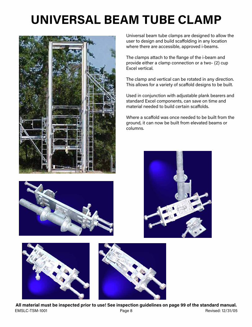
UNIVERSAL BEAM TUBE CLAMPUniversal beam tube clamps are designed to allow the user to design and build scaffolding in any location where there are accessible, approved i-beams.
The clamps attach to the flange of the i-beam and provide either a clamp connection or a two- (2) cup Excel vertical.
The clamp and vertical can be rotated in any direction. This allows for a variety of scaffold designs to be built.
Used in conjunction with adjustable plank bearers and standard Excel components, can save on time and material needed to build certain scaffolds.
Where a scaffold was once needed to be built from the ground, it can now be built from elevated beams or columns.
All material must be inspected prior to use! See inspection guidelines on page 99 of the standard manual.EMSLC-TSM-1001 Page 9 Revised: 12/31/05
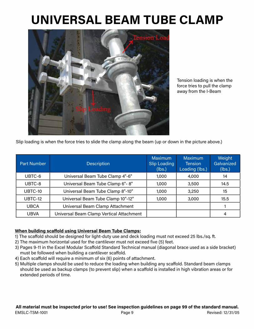
UNIVERSAL BEAM TUBE CLAMP
Tension loading is when the force tries to pull the clamp away from the I-Beam
Part Number DescriptionMaximum
Slip Loading (lbs.)
Maximum Tension
Loading (lbs.)
Weight Galvanized
(lbs.)UBTC-6 Universal Beam Tube Clamp 4"-6" 1,000 4,000 14
UBTC-8 Universal Beam Tube Clamp 6"- 8" 1,000 3,500 14.5
UBTC-10 Universal Beam Tube Clamp 8"-10" 1,000 3,250 15
UBTC-12 Universal Beam Tube Clamp 10"-12" 1,000 3,000 15.5
UBCA Universal Beam Clamp Attachment 1
UBVA Universal Beam Clamp Vertical Attachment 4
When building scaffold using Universal Beam Tube Clamps:1) The scaffold should be designed for light-duty use and deck loading must not exceed 25 lbs./sq. ft.2) The maximum horizontal used for the cantilever must not exceed five (5) feet.3) Pages 9-11 in the Excel Modular Scaffold Standard Technical manual (diagonal brace used as a side bracket)
must be followed when building a cantilever scaffold.4) Each scaffold will require a minimum of six (6) points of attachment.5) Multiple clamps should be used to reduce the loading when building any scaffold. Standard beam clamps
should be used as backup clamps (to prevent slip) when a scaffold is installed in high vibration areas or for extended periods of time.
Slip loading is when the force tries to slide the clamp along the beam (up or down in the picture above.)

All material must be inspected prior to use! See inspection guidelines on page 99 of the standard manual.EMSLC-TSM-1001 Page 10 Revised: 12/31/05
VERTICAL LEG HANGING BRACKET
Part Number DescriptionMaximum Allowable Load (lbs.)
Galvanized Weight (lbs.)
VLHB Vertical Leg Hanging Bracket 7,500 15
Note:1) The vertical leg hanging bracket allows the user to either hang a scaffold leg from the bottom of the bracket,
or extend the scaffold up using the built in coupling pin.2) When suspending a scaffold, a vertical leg connector shall be used and the load of the scaffold shall be taken
into consideration when designing the scaffold.3) Both the bottom and top bracket should always be installed when using the vertical leg hanging bracket.4) Vertical leg hanging bracket spacers are used to fit beams that have a larger top flange and come in various
sizes.
Clamp bolt tension greatly affects the slip loading.Clamp bolts should be tightened between 40 and 65 ft-lbs. Overtightening could damage the threads, bolt or item the clamp is attached to. Undertightening could result in clamps slipping at lower than rated loads.
<<< CAUTION: There is a pinch point located where the beam sides are located on the clamp.>>>

All material must be inspected prior to use! See inspection guidelines on page 99 of the standard manual.EMSLC-TSM-1001 Page 11 Revised: 12/31/05
LIFTING AND MOVING EXCEL MODULAR SCAFFOLD
Part Number DescriptionMaximum
Supported Load (lbs.)
Galvanized Weight
LD1 Lifting Device 2,400 9
VLC Vertical Leg Connector 7,500 7
VPC Vertical Locking Clamp 2,400 9.5
Lifting Device
Vertical Leg Connector
The following components are provided to enable fully-assembled Excel Modular Scaffolds to be lifted and moved. This enables a section of scaffold to be assembled in a low-hazard area and moved into a more dangerous or high-hazard area, thereby reducing employee exposure in those areas.
The lifting device attaches to the top of the vertical post. It is designed to accept a shackle for a sling/cable attachment.
The vertical locking connector and vertical locking clamp are designed to provide added strength to the vertical post connection.
Either the vertical locking connector or vertical locking clamp must be installed on all vertical posts at the pin connection before lifting the scaffold.
Vertical Locking Clamp
Notes:1) All OSHA and plant safety regulations governing rigging and material handling must be followed.2) All loose material must be removed from the scaffold before it is lifted.3) Spreader beams must be used, so that the lifting load on all vertical posts is applied in an upward direction.4) The scaffold must be properly braced to prevent deformation during movement.5) Scaffold weight loads must be calculated to prevent the overloading of any scaffold or lifting component.6) All scaffold components (deck boards, etc.) must be secured to the scaffold.
Clamp bolts should be tightened between 40 and 65 ft-lbs. Overtightening could damage the threads, bolts or item the clamp is attached to.
The snap button must be fully engaged in both ends of the vertical post connections.

All material must be inspected prior to use! See inspection guidelines on page 99 of the standard manual.EMSLC-TSM-1001 Page 12 Revised: 03/03/13
EXCEL MODULAR SKID PANS
Part Number Description Bottom Length (ft.)
Full Length (ft.)
Empty Weight Galvanized (lbs.)
Maximum Allowable Total Load (lbs.)
Skid-8 8' Long Skid Pan 6 8 900 3,000
Skid-10 10' Long Skid Pan 8 10 1,050 3,000Maximum allowable loads shown includes the weight of the skid pan plus pan’s content.
When not in use, the skid pan and all associated lifting components shall be stored in such a way to protect the life of the equipment.
Skid pans are used to move scaffold material from a ground level closer to the location the material is required. This may be a higher elevation or across obstructions, such as fences, roads, streams, etc.
Skid pans come in different sizes and shapes depending on the intended use. The following guidelines must be followed, regardless of the type of skid pan used:
1) All skid pans, cables, shackles and associated lifting equipment must be thoroughly inspected by the designated person when first delivered to the jobsite. The inspection must meet the requirements as defined in ASME B30.20-1-3. a) A visual inspection must be performed by a qualified person making records of the apparent external condition
to provide the basis for a continuing evaluation. b) The inspection must be documented, dated and signed by the person performing the inspection.
2) For all equipment inspect: a) Structural members for deformation, cracks or excessive wear. b) Loose or missing guards, fasteners, covers, stops or name plates. c) All functional operating mechanisms for mis-adjustments interfering with operation. d) Deformation—Any bending or twisting exceeding 10 degrees (or as recommended by the manufacturer) from
the normal plane.e) Throat opening—Any distortion causing an increase in the throat opening exceeding 15% (or as recommended
by the manufacturer).f) Wear—Any wear exceeding 10% (or as recommended by the manufacturer) of the original section dimensions.
3) Frequent visual examinations shall be performed weekly (or more frequently if recommended by the designated person) while the equipment is in service. NO records required.
4) A documented thorough inspection shall be performed any time there is reason to believe part of the lifting equipment may have been damaged during use.
5) A skid pan shall not be used if it does not contain a label plate that lists the manufacturer, a serial number and the rated load.

All material must be inspected prior to use! See inspection guidelines on page 99 of the standard manual.EMSLC-TSM-1001 Page 13 Revised: 3/27/13
ADJUSTABLE TUBE AND CLAMP ADAPTER
Part Number Description Galvanized Weight (lbs.)
Maximum Allowable Load (lbs.) @ 12” Extension
ATCA Adjustable Tube and Clamp Adapter 12 5,000
The adjustable tube and clamp adapter is designed to allow the elevation of a board deck to be changed, so that the top portion of a scaffold can be aligned with a scaffold built on a separate structure.
This allows the vertical cups of one scaffold to be aligned with another scaffold built at a different elevation.
Note:1) There must always be a minimum of six (6) inches of thread inside the upper and lower vertical.2) Only one (1) adjustable tube and clamp adapter may be used in any run of verticals.3) Before use, inspect the adjustable tube and clamp adapter assembly to ensure there are no cracks in the
wing nuts and verify that the three (3) tack welds are visibly in place.4) The maximum spacing between the nuts is twelve (12) inches.
The adjustable tube and clamp adapter may be placed on top of an existing Excel Modular Scaffold or tube and clamp scaffold.
There must be a wrap of horizontals (either Excel Modular or tube and clamp) attached to the verticals above and below the adjustable tube and clamp adapter.
All material must be inspected prior to use! See inspection guidelines on page 99 of the standard manual.EMSLC-TSM-1001 Page 14 Revised: 03/27/13
EXCEL MODULAR ROOF ADAPTER
Part Number Description Maximum Allowable Load = F (lbs.)
Galvanized Weight (lbs.)
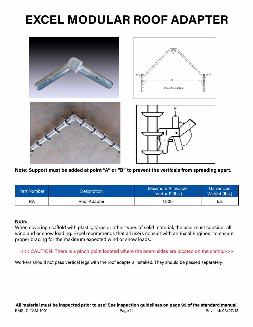
RA Roof Adapter 1,000 5.8
Note: Support must be added at point “A” or “B” to prevent the verticals from spreading apart.
Note:When covering scaffold with plastic, tarps or other types of solid material, the user must consider all wind and or snow loading. Excel recommends that all users consult with an Excel Engineer to ensure proper bracing for the maximum expected wind or snow loads.
<<< CAUTION: There is a pinch point located where the beam sides are located on the clamp.>>>
Workers should not pass vertical legs with the roof adapters installed. They should be passed separately.

All material must be inspected prior to use! See inspection guidelines on page 99 of the standard manual.EMSLC-TSM-1001 Page 15 Revised: 03/27/13
EXCEL MODULAR COUNTERWEIGHT BASE PLATE
Single guardrail sets must have a minimum of four (4) counterweight base plates installed and two (2) outriggers.
Multiple guardrail sets must have a minimum of one (1) counterweight base plate for each five (5) feet of guardrail.
Setup required for multiple guardrail sets: Part “A” sizes six (6) to ten (10) feet in length.
Setup required for multiple guardrail sets: Part “B” sizes up to five (5) feet in length.
Counterweight base plates are designed to provide handrail protection for floor openings or other hazards where it is necessary to prevent access.
Counterweight base plates do not require any tie offs to permanent plant components.
Counterweight base plates are rubber backed to prevent damage to the floor surface.
Counterweight base plates can be installed on roof tops that require working near a roof edge.
Counterweight base plates can be used to help stabilize a scaffold where counterweights are required (i.e. lunch tents, outrigger scaffolds, etc.).
All guardrails must have a handrail and mid-rail, and should be installed at the same elevations, as required by scaffold handrails and mid-rails in accordance with CFR 29 1926 subpart “L”.

All material must be inspected prior to use! See inspection guidelines on page 99 of the standard manual.EMSLC-TSM-1001 Page 16 Revised: 08/01/06
EXCEL MODULAR COUNTERWEIGHT BASE PLATE
Part Number Description Galvanized Weight (lbs.)
CWBP Counterweight Base Plate 80
Guardrail Part A (ft.)
Minimum Size of Support Bar B (ft.)
10 7
9 7
8 6
7 6
6 6
5 5
4 5
3 5
Safety Notes:1) Guardrail systems should always be installed and signed off on by a competent person before pulling any
floor plugs or removing deck grating.2) When installing a guardrail system on rooftops, personal fall protection must be used until the guardrail
system has been completely installed.3) Leading-edge guardrail system base plates must be set back a minimum of six (6) feet of the opening being
protected.4) Guardrail system must be inspected by the end-user before each and every use to ensure it has not been
modified.5) Guardrail system base plates weigh 80 lbs. and should be handled by two or more persons, or the proper
lifting equipment.6) Guardrail systems should never be used on dirt, gravel or other surfaces that could allow the base plate to
sink or slide.

All material must be inspected prior to use! See inspection guidelines on page 99 of the standard manual.EMSLC-TSM-1001 Page 17 Revised: 08/01/06
EXCEL MODULAR TROLLEY SYSTEM
The pulley assembly may be placed anywhere on the truss.
The maximum load capacity for a vertical lift is 3,000 lbs.The trolley system is not designed for side loading and should never be used to pick up any load not aligned with the trolley.Horizontal members shall be placed at a maximum of every twelve (12) cups (69 inches apart).
Multiple hoists may be used for longer loads, as long as the total weight of 3,000 lbs. is not exceeded, or is designed by an Excel Engineer.
All material must be inspected prior to use! See inspection guidelines on page 99 of the standard manual.EMSLC-TSM-1001 Page 18 Revised: 10/22/10
EXCEL MODULAR TROLLEY SYSTEM
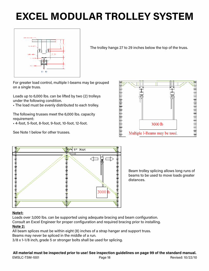
The trolley hangs 27 to 29 inches below the top of the truss.
For greater load control, multiple I-beams may be grouped on a single truss.
Loads up to 6,000 lbs. can be lifted by two (2) trolleys under the following condition.• The load must be evenly distributed to each trolley.
The following trusses meet the 6,000 lbs. capacity requirement:• 4-foot, 5-foot, 8-foot, 9-foot, 10-foot, 12-foot.
See Note 1 below for other trusses.
Beam trolley splicing allows long runs of beams to be used to move loads greater distances.
Note1:Loads over 3,000 lbs. can be supported using adequate bracing and beam configuration.Consult an Excel Engineer for proper configuration and required bracing prior to installing.Note 2:All beam splices must be within eight (8) inches of a strap hanger and support truss.Beams may never be spliced in the middle of a run. 3/8 x 1-1/8 inch, grade 5 or stronger bolts shall be used for splicing.
All material must be inspected prior to use! See inspection guidelines on page 99 of the standard manual.EMSLC-TSM-1001 Page 19 Revised: 10/22/10
EXCEL MODULAR TROLLEY SYSTEM
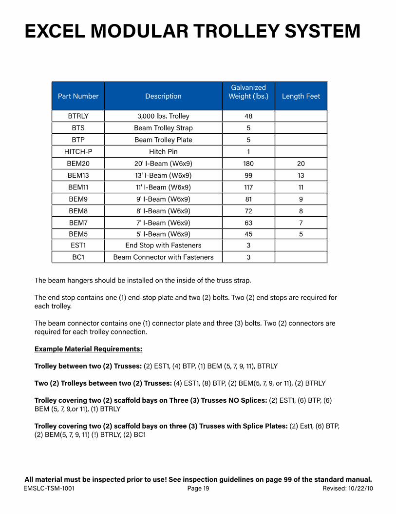
Part Number DescriptionGalvanized
Weight (lbs.) Length Feet
BTRLY 3,000 lbs. Trolley 48
BTS Beam Trolley Strap 5
BTP Beam Trolley Plate 5
HITCH-P Hitch Pin 1
BEM20 20' I-Beam (W6x9) 180 20
BEM13 13' I-Beam (W6x9) 99 13
BEM11 11' I-Beam (W6x9) 117 11
BEM9 9' I-Beam (W6x9) 81 9
BEM8 8' I-Beam (W6x9) 72 8
BEM7 7' I-Beam (W6x9) 63 7BEM5 5' I-Beam (W6x9) 45 5EST1 End Stop with Fasteners 3
BC1 Beam Connector with Fasteners 3
The beam hangers should be installed on the inside of the truss strap.
The end stop contains one (1) end-stop plate and two (2) bolts. Two (2) end stops are required for each trolley.
The beam connector contains one (1) connector plate and three (3) bolts. Two (2) connectors are required for each trolley connection.
Example Material Requirements:
Trolley between two (2) Trusses: (2) EST1, (4) BTP, (1) BEM (5, 7, 9, 11), BTRLY
Two (2) Trolleys between two (2) Trusses: (4) EST1, (8) BTP, (2) BEM(5, 7, 9, or 11), (2) BTRLY
Trolley covering two (2) scaffold bays on Three (3) Trusses NO Splices: (2) EST1, (6) BTP, (6) BEM (5, 7, 9,or 11), (1) BTRLY
Trolley covering two (2) scaffold bays on three (3) Trusses with Splice Plates: (2) Est1, (6) BTP, (2) BEM(5, 7, 9, 11) (!) BTRLY, (2) BC1
All material must be inspected prior to use! See inspection guidelines on page 99 of the standard manual.EMSLC-TSM-1001 Page 20 Revised: 12/31/05
EXCEL MODULAR TROLLEY SYSTEM
Notes:
1) The trusses supporting the trolley system should not be used to support a scaffold board deck.2) The trolley must not be allowed to pass the outer most truss.3) The vertical support for the trusses must be designed to support the required loads.4) All end stops and connector plates must be installed before the trolley system is used.5) The trolley beam must be level when installed.6) Do not substitute other components for connectors, end stops, trolley straps, bolts, etc.7) Extra bracing is required when installing a trolley system. Bracing should be added to prevent
shifting in the direction of movement.8) Mechanical means shall never be used to move the load.9) Sudden starts and stops must be prevented.
The trolley should be periodically maintained. If there are grease points, they should be filled with white lithium grease (ST-80 High-Performance Grease or equivalent).
Trolleys without grease points should be lubed with a 10-weight oil.
WD-40 can be used before application of grease or oil to loosen old grease and remove any rust buildup.
Unless a special beam is used or the maximum load decreased, regardless of the beam length, each trolley system beam must be supported with a beam trolley strap kit every seven (7) ft.
All material must be inspected prior to use! See inspection guidelines on page 99 of the standard manual.EMSLC-TSM-1001 Page 21 Revised: 08/01/06
EXCEL MODULAR DAVIT ARM
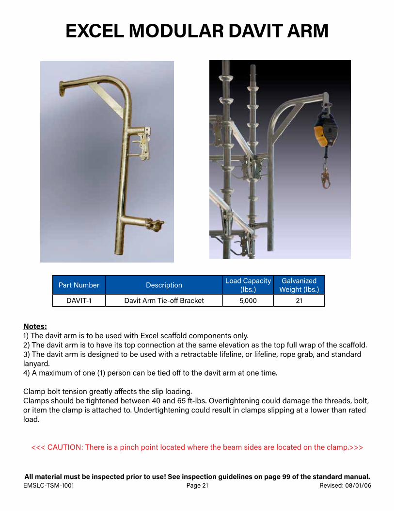
Part Number Description Load Capacity (lbs.)
Galvanized Weight (lbs.)
DAVIT-1 Davit Arm Tie-off Bracket 5,000 21
Notes:1) The davit arm is to be used with Excel scaffold components only.2) The davit arm is to have its top connection at the same elevation as the top full wrap of the scaffold.3) The davit arm is designed to be used with a retractable lifeline, or lifeline, rope grab, and standard lanyard.4) A maximum of one (1) person can be tied off to the davit arm at one time.
Clamp bolt tension greatly affects the slip loading.Clamps should be tightened between 40 and 65 ft-lbs. Overtightening could damage the threads, bolt, or item the clamp is attached to. Undertightening could result in clamps slipping at a lower than rated load.
<<< CAUTION: There is a pinch point located where the beam sides are located on the clamp.>>>
All material must be inspected prior to use! See inspection guidelines on page 99 of the standard manual.EMSLC-TSM-1001 Page 22 Revised: 12/31/05
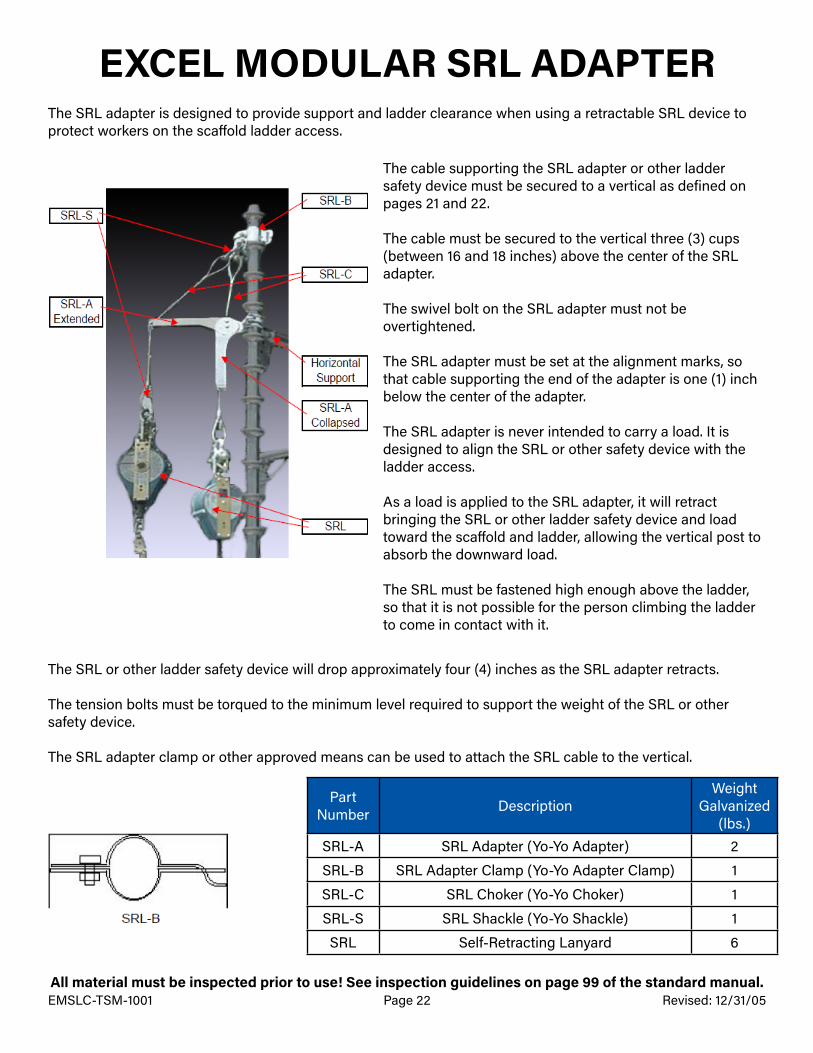
EXCEL MODULAR SRL ADAPTER
The cable supporting the SRL adapter or other ladder safety device must be secured to a vertical as defined on pages 21 and 22.
The cable must be secured to the vertical three (3) cups (between 16 and 18 inches) above the center of the SRL adapter.
The swivel bolt on the SRL adapter must not be overtightened.
The SRL adapter must be set at the alignment marks, so that cable supporting the end of the adapter is one (1) inch below the center of the adapter.
The SRL adapter is never intended to carry a load. It is designed to align the SRL or other safety device with the ladder access.
As a load is applied to the SRL adapter, it will retract bringing the SRL or other ladder safety device and load toward the scaffold and ladder, allowing the vertical post to absorb the downward load.
The SRL must be fastened high enough above the ladder, so that it is not possible for the person climbing the ladder to come in contact with it.
The SRL adapter is designed to provide support and ladder clearance when using a retractable SRL device to protect workers on the scaffold ladder access.
The SRL or other ladder safety device will drop approximately four (4) inches as the SRL adapter retracts.
The tension bolts must be torqued to the minimum level required to support the weight of the SRL or other safety device.
The SRL adapter clamp or other approved means can be used to attach the SRL cable to the vertical.
Part Number Description
Weight Galvanized
(lbs.)SRL-A SRL Adapter (Yo-Yo Adapter) 2
SRL-B SRL Adapter Clamp (Yo-Yo Adapter Clamp) 1
SRL-C SRL Choker (Yo-Yo Choker) 1
SRL-S SRL Shackle (Yo-Yo Shackle) 1
SRL Self-Retracting Lanyard 6
All material must be inspected prior to use! See inspection guidelines on page 99 of the standard manual.EMSLC-TSM-1001 Page 23 Revised: 12/31/05
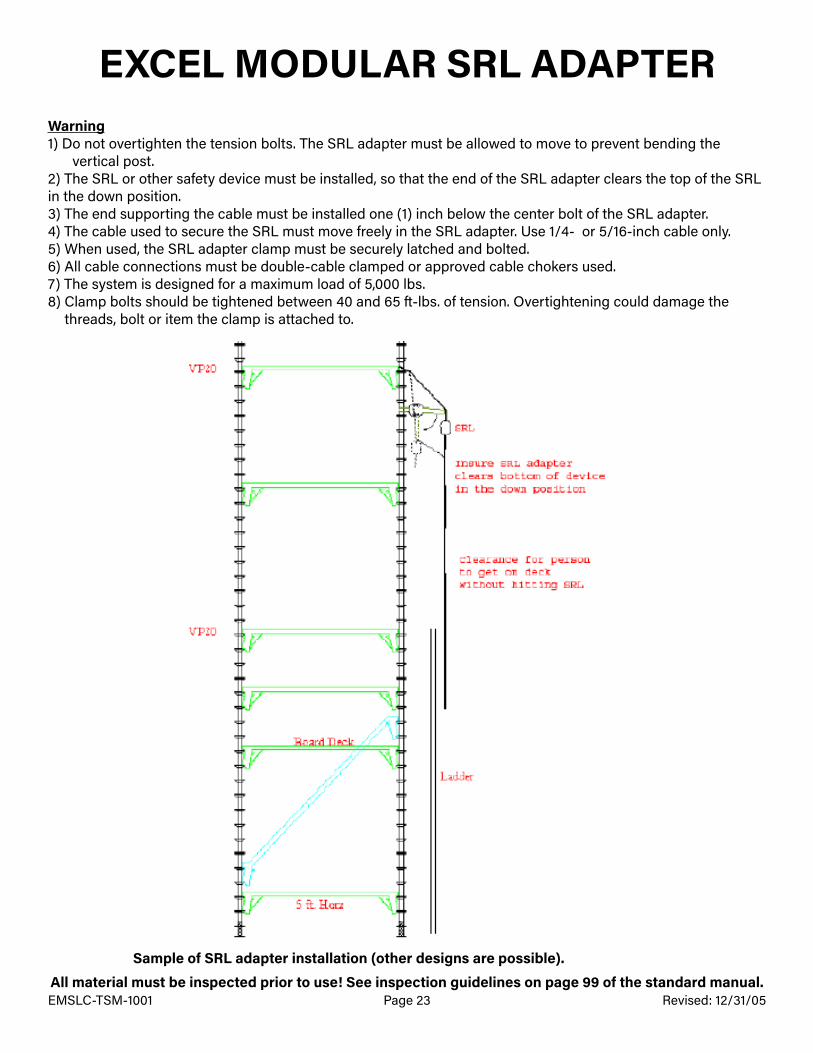
EXCEL MODULAR SRL ADAPTERWarning1) D o not overtighten the tension bolts. The SRL adapter must be allowed to move to prevent bending the
vertical post.2) The SRL or other safety device must be installed, so that the end of the SRL adapter clears the top of the SRL in the down position.3) The end supporting the cable must be installed one (1) inch below the center bolt of the SRL adapter.4) The cable used to secure the SRL must move freely in the SRL adapter. Use 1/4- or 5/16-inch cable only.5) When used, the SRL adapter clamp must be securely latched and bolted.6) All cable connections must be double-cable clamped or approved cable chokers used.7) The system is designed for a maximum load of 5,000 lbs.8) Clamp bolts should be tightened between 40 and 65 ft-lbs. of tension. Overtightening could damage the
threads, bolt or item the clamp is attached to.
Sample of SRL adapter installation (other designs are possible).
EMSLC-TSM-1001 Page 24All material must be inspected prior to use! See inspection guidelines on page 99 of the standard manual.
Revised: 12/31/05
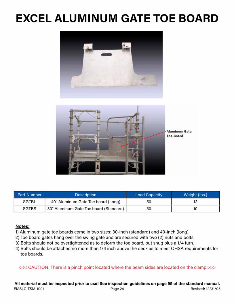
EXCEL ALUMINUM GATE TOE BOARD
Part Number Description Load Capacity Weight (lbs.)
SGTBL 40" Aluminum Gate Toe board (Long) 50 12
SGTBS 30" Aluminum Gate Toe board (Standard) 50 10
Notes:1) Aluminum gate toe boards come in two sizes: 30-inch (standard) and 40-inch (long).2) Toe board gates hang over the swing gate and are secured with two (2) nuts and bolts.3) Bolts should not be overtightened as to deform the toe board, but snug plus a 1/4 turn.4) Bolts should be attached no more than 1/4 inch above the deck as to meet OHSA requirements for
toe boards.
<<< CAUTION: There is a pinch point located where the beam sides are located on the clamp.>>>

EMSLC-TSM-1001 Page 25All material must be inspected prior to use! See inspection guidelines on page 99 of the standard manual.
Revised: 10/14/09
EXCEL SCAFFOLD TIE-OFF LUG
Part Number Description Maximum Load (lbs.) Weight (lbs.)
TOL Tie-Off Lug 5,000 2.5
Tie-off lugs are considered part of a personal fall arrest system and are available for sale only.
Notes:1) The tie-off lug is to be used with Excel scaffold only.2) The tie-off lug is to be placed over an existing coupling pin and slid down to sit firmly against the
vertical post.3) Tie-off lugs can be used with either standard lanyards or SRL devices.4) A maximum of one (1) tie-off lug and one (1) person can be tied off to a vertical post at one time.5) If a fall occurs, the tie-off lug and related fall protection components shall be immediately removed
from service and given to a supervisor or manager. Excel’s Safety Department should be notified immediately.
**For Purchase Only

EMSLC-TSM-1001 Page 26All material must be inspected prior to use! See inspection guidelines on page 99 of the standard manual.
Revised: 12/31/05
EXCEL ELEVATOR STRUT ASSEMBLY
Part Number Description Load Capacity (lbs.) Weight (lbs.)
H-Plate H-Plate for Back of Beam at Vertical with Bolts 15,000 42
PAS Telescoping Adjustable Power Strut 15,000 220
SAS Welded Strut Attachment with Shoe 15,000 84
S-Beam Beam with Strut Plates 15,000 N/A
Notes:1) The elevator strut assembly shall only be used with Excel scaffolding equipment.2) Elevator strut assembly shall be designed by a qualified Excel Engineer and have P.E. stamped drawings
made prior to installation.3) The strut assembly is a custom system and must be designed for each application.4) Only approved beams shall be used when installing the strut assembly.
Clamp and bolt torques greatly affects the slip loading.
Bolts attaching the plates to the vertical shall be tightened to 85 ft-lbs. Overtightening could damage the threads, bolts or items the assembly is attached to. Undertightening could result in the slipping at lower than rated loads.
<<< CAUTION: There is a pinch point located where the beam sides are located on the clamp.>>>
EMSLC-TSM-1001 Page 27All material must be inspected prior to use! See inspection guidelines on page 99 of the standard manual.
Revised: 12/31/05
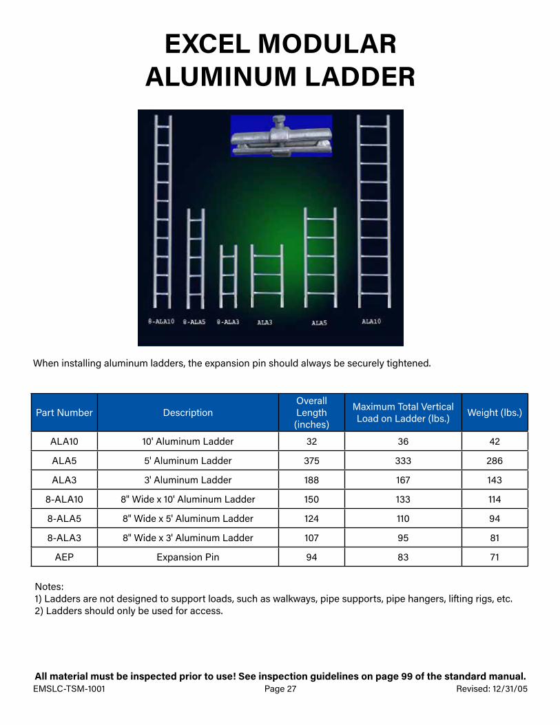
EXCEL MODULAR ALUMINUM LADDER
Part Number DescriptionOverall Length (inches)
Maximum Total Vertical Load on Ladder (lbs.) Weight (lbs.)
ALA10 10' Aluminum Ladder 32 36 42
ALA5 5' Aluminum Ladder 375 333 286
ALA3 3' Aluminum Ladder 188 167 143
8-ALA10 8" Wide x 10' Aluminum Ladder 150 133 114
8-ALA5 8" Wide x 5' Aluminum Ladder 124 110 94
8-ALA3 8" Wide x 3' Aluminum Ladder 107 95 81
AEP Expansion Pin 94 83 71
When installing aluminum ladders, the expansion pin should always be securely tightened.
Notes:1) Ladders are not designed to support loads, such as walkways, pipe supports, pipe hangers, lifting rigs, etc.2) Ladders should only be used for access.

EMSLC-TSM-1001 Page 28All material must be inspected prior to use! See inspection guidelines on page 99 of the standard manual.
Revised: 10/14/09
EXCEL MODULAR ALUMINUM STAIR SYSTEM
Part Number Description Weight (lbs.)DIS42 Drop-In Aluminum Stair Unit 42” Bay 120
Stairs can be designed using side brackets or multi-bay scaffolds
Aluminum stairs are built as a single complete drop in unit. The unit is 34 inches wide and designed to work with a 42-inch wide bay (using 42-inch horizontals as bearers), and used with 7-foot runners. Completed bay size for the aluminum stair tower will be 7-feet wide (comprised of two (2) 42-inch bays) x 7-feet long (using 7-foot horizontals as runners).
Notes:1) All aluminum stair bays are rated with a light-duty rating of 25 psf.2) Excel half clamp braces or diagonal extendable braces should be used with the pins removed or buttons
compressed for stair handrails.3) Aluminum stair bays can be used with universal steel stair stringers.4) To transition from a universal stair stringer to a drop-in aluminum stair unit bay or vice versa, a three- (3) foot
metal plank should be used with the universal stair stringer.5) Stair systems are to be inspected prior to each shift. This includes treads, risers and hand-rails. The stairs
should also be tied with #9 wire in heavy wind conditions.
Warning:Improper use of stairs could cause serious injury. Always use handrails and step in the center of the stair treads. Always walk down the stairs, do not run or skip treads. Non-skid adhesive tape may be placed on the edge of the treads for better traction.
EMSLC-TSM-1001 Page 29All material must be inspected prior to use! See inspection guidelines on page 99 of the standard manual.
Revised: 10/14/09
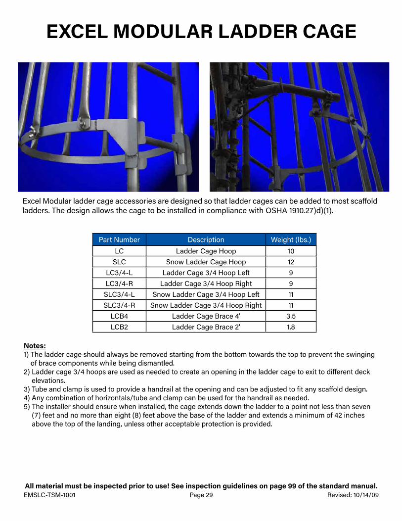
EXCEL MODULAR LADDER CAGE
Part Number Description Weight (lbs.)LC Ladder Cage Hoop 10
SLC Snow Ladder Cage Hoop 12LC3/4-L Ladder Cage 3/4 Hoop Left 9LC3/4-R Ladder Cage 3/4 Hoop Right 9
SLC3/4-L Snow Ladder Cage 3/4 Hoop Left 11SLC3/4-R Snow Ladder Cage 3/4 Hoop Right 11
LCB4 Ladder Cage Brace 4' 3.5LCB2 Ladder Cage Brace 2' 1.8
Notes:1) The ladder cage should always be removed starting from the bottom towards the top to prevent the swinging
of brace components while being dismantled.2) Ladder cage 3/4 hoops are used as needed to create an opening in the ladder cage to exit to different deck
elevations.3) Tube and clamp is used to provide a handrail at the opening and can be adjusted to fit any scaffold design.4) Any combination of horizontals/tube and clamp can be used for the handrail as needed.5) The installer should ensure when installed, the cage extends down the ladder to a point not less than seven
(7) feet and no more than eight (8) feet above the base of the ladder and extends a minimum of 42 inches above the top of the landing, unless other acceptable protection is provided.
Excel Modular ladder cage accessories are designed so that ladder cages can be added to most scaffold ladders. The design allows the cage to be installed in compliance with OSHA 1910.27)d)(1).

EMSLC-TSM-1001 Page 30All material must be inspected prior to use! See inspection guidelines on page 99 of the standard manual.
Revised: 10/14/09
EXCEL MODULAR RAPID ACCESS SYSTEM
The Excel rapid access system is designed to provide “stair-like” scaffold access in areas where there is not enough room for a scaffold stair tower. The rapid access system was designed specifically to facilitate getting a worker onto work platforms safely and quickly.
Notes:1) Workers climb the inside of the scaffold tower. The maximum fall is limited to the deck height.2) The opening is a full 36-inches square, which accommodates the majority of workers and their tools.3) The opening is fully handrailed around the opening to prevent accidental falls back into access.4) The rapid access system uses a standard swing gate attached to the horizontal bar for stepping off of the
ladder onto the work deck.5) Allows for the insertion of a standard eight- (8) cup vertical leg gate post to the middle of the board deck.6) Telescoping plank bearer goes under the long deck boards, while allowing the attachment of the shorter deck
boards required for the opening.7) The rapid access system will easily accommodate construction of tower sizes ranging from
five (5) feet x six (6) feet and up to seven (7) feet x ten (10) feet without major design changes.8) Workers are no longer required to climb straight up long vertical ladders, or go over or under mid-rail or top
handrails to get onto the work platform.9) Adjustable hooks allow the ladder to remain at a thirty-degree angle, which requires less effort to climb and
reduces slip hazards.10) The rapid access system will accept telescoping metal toe boards to secure deck boards to the bearers.11) The rapid access system was specifically designed so that it could be used with other modular scaffold
systems with minor modifications.12) The rapid access system does not require any special tools for installation and only a minimal amount of in
service training.13) The rapid access system is only meant to be used in light-duty applications and is limited to a maximum
loading of no more then 25 psf.14) For scaffolds greater than one (1) work deck high, the rapid access system entrances must be installed
in opposite corners of the work platform. The rapid access system is not designed to allow the ladders accesses to be placed on top of each other in the same corner.

EMSLC-TSM-1001 Page 31All material must be inspected prior to use! See inspection guidelines on page 99 of the standard manual.
Revised: 10/14/09
EXCEL MODULAR RAPID ACCESS SYSTEM
Rapid access system ladder hooks are easily installed and are attached over the top of a horizontal to provide support for the ladder.
The rapid access system telescoping plank bearer is adjustable for scaffold widths from five (5) foot to nine (9) foot. It is used to provide support for the board deck and supplies a vertical pin connection that allows an eight- (8) cup vertical to be installed for the gate, mid-rail and handrail.
The rapid access system handrail adapter has an Excel end connector on one end and a clamp on the other. It is designed to connect a standard vertical to the middle of any horizontal. For the rapid access system, it is used as the handrail and mid-rail on the back side of the floor opening.
EMSLC-TSM-1001 Page 32All material must be inspected prior to use! See inspection guidelines on page 99 of the standard manual.
Revised: 10/14/09
EXCEL MODULAR RAPID ACCESS SYSTEM
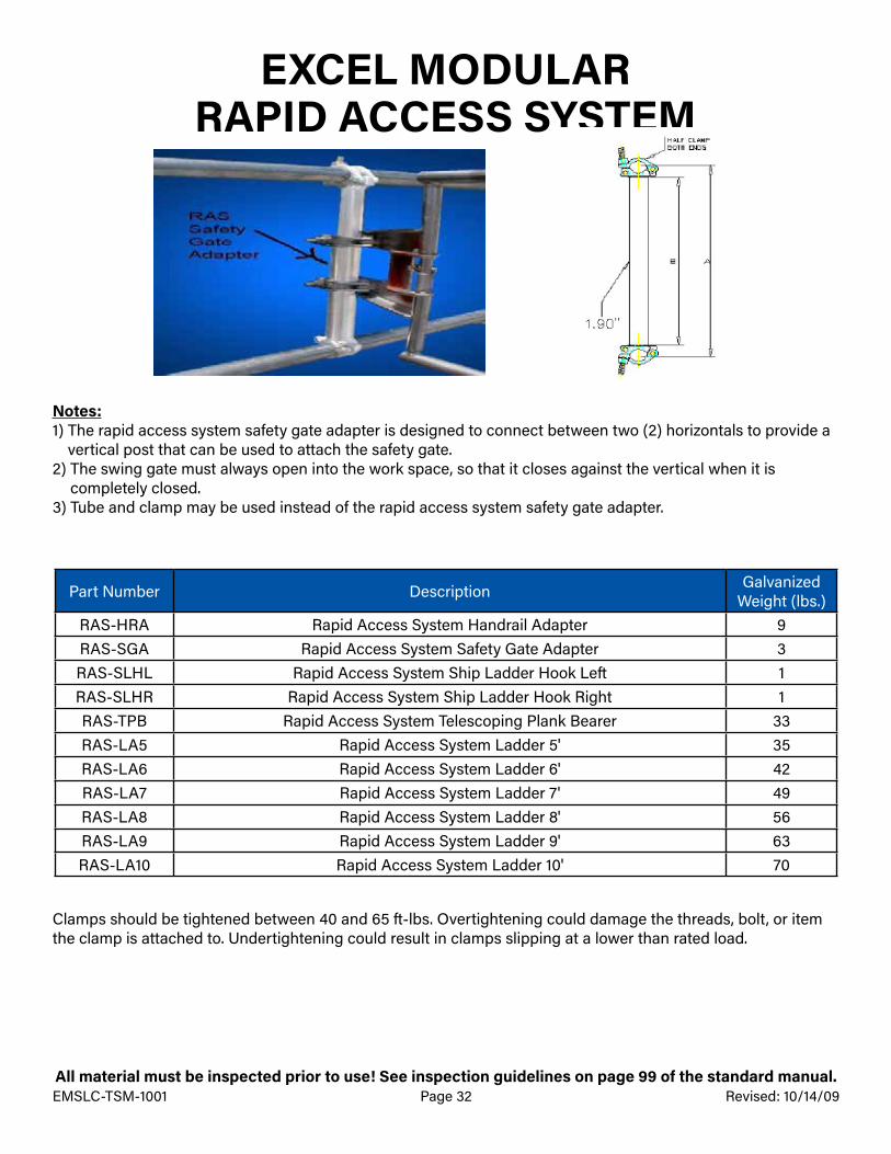
Part Number Description Galvanized Weight (lbs.)
RAS-HRA Rapid Access System Handrail Adapter 9RAS-SGA Rapid Access System Safety Gate Adapter 3RAS-SLHL Rapid Access System Ship Ladder Hook Left 1RAS-SLHR Rapid Access System Ship Ladder Hook Right 1RAS-TPB Rapid Access System Telescoping Plank Bearer 33RAS-LA5 Rapid Access System Ladder 5' 35RAS-LA6 Rapid Access System Ladder 6' 42RAS-LA7 Rapid Access System Ladder 7' 49RAS-LA8 Rapid Access System Ladder 8' 56RAS-LA9 Rapid Access System Ladder 9' 63RAS-LA10 Rapid Access System Ladder 10' 70
Notes:1) The rapid access system safety gate adapter is designed to connect between two (2) horizontals to provide a
vertical post that can be used to attach the safety gate. 2) The swing gate must always open into the work space, so that it closes against the vertical when it is
completely closed.3) Tube and clamp may be used instead of the rapid access system safety gate adapter.
Clamps should be tightened between 40 and 65 ft-lbs. Overtightening could damage the threads, bolt, or item the clamp is attached to. Undertightening could result in clamps slipping at a lower than rated load.

EMSLC-TSM-1001 Page 33All material must be inspected prior to use! See inspection guidelines on page 99 of the standard manual.
Revised: 10/14/09
EXCEL MODULAR SHORING POSTS
Shoring Post Head
Shoring Post JackSHP10 SHP8 SHP6 SHP4 SHP2
Part Number DescriptionEffective Length (inches)
Overall Length (inches)
Galvanized Weight (lbs.)
SHP2 2-Cup Shoring Post 11.5" 11.5 18.5 26
SHP4 4-Cup Shoring Post 23" 23 30 30
SHP6 6-Cup Shoring Post 34.5" 34.5 41.5 41.3
SHP8 8-Cup Shoring Post 46" 46 53 52.6
SHP10 10-Cup Shoring Post 57.5" 57.5 64.5 52.6
LSH Large Shoring Head 46 60 94
LHJ Large Shoring Jack 46 60 93
BAC Big Swivel Clamp (3.5"X2") 6.7
Notes:1) The pin material is made out of 3.0 OD 1/4-inch wall DOM tubing.2) The shoring post material is made out of standard 3.5 inch OD Schedule 40 material.3) Cup spacing is 5.75 inches, the same as standard Excel verticals.4) Shoring posts are 100% compatible with standard Excel material and may be intermixed as needed to provide
the best design.5) Due to the diameter of the Excel shoring verticals, standard length pans will not fit between the spacing of the
horizontals. This is due to increased spacing of 1-21/32 inches. All shoring must be approved by an Excel Engineer and P.E. if required by the customer’s safety regulations.<<< CAUTION: There are pinch points where the vertical meet, and where the screw jack meet the verticals. >>>
Shoring Post

EMSLC-TSM-1001 Page 34All material must be inspected prior to use! See inspection guidelines on page 99 of the standard manual.
Revised: 04/25/14
EXCEL MODULAR SHORING POSTS
Unbraced Post Length (inches)
Maximum Allowable Compressive Load When
Rated for Scaffold Use (lbs.)
Maximum Allowable Compressive Load When
Rated for Shoring Use (lbs.)46 25,000 35,000
23 27,500 37,500
Unbraced 46 inches Unbraced 23 inches
Notes:1) Shoring posts are 100% compatible with Excel standard horizontals and trusses and may be intermixed as
needed to provide the best design.2) Diagonal bracing is comprised of standard pipe and 3.5- x 2-inch swivel clamps.
Allowable loads when rated for scaffold use, include OSHA (4:1) safety factor.When designing scaffolds with unique configurations or special loading conditions, drawings must be provided by an Excel Engineer, as well as the drawing be P.E. stamped.
Allowable loads when rated for shoring use, include OSHA (2.5:1) safety factor.All shoring applications shall have a drawing provided by an Excel Engineer and require a P.E. stamp.
All shoring designs must be approved by a professional engineer.

EMSLC-TSM-1001 Page 35All material must be inspected prior to use! See inspection guidelines on page 99 of the standard manual.
Revised: 12/31/05
EXCEL MODULAR SHORING JACK
Shoring Head Shoring Jack
Unbraced Post Length (inches)
Maximum Allowable Compressive Load When
Rated for Scaffold Use (lbs.)
Maximum Allowable Compressive Load When
Rated for Shoring Use (lbs.)46 25,000 35,000
23 27,500 37,500
Notes:1) Shoring head and jacks are 100% compatible with Excel standard horizontals, and trusses and may be
intermixed as needed to provide the best design.2) Diagonal bracing is comprised of standard pipe and 3.5 x 2 inch swivel clamps.
Allowable loads when rated for scaffold use, include OSHA (4:1) safety factor.When designing scaffolds with unique configurations or special loading conditions, drawings must be provided by an Excel Engineer, as well as the drawing be P.E. stamped.
Allowable loads when rated for shoring use, include OSHA (2.5:1) safety factor.All shoring applications shall have a drawing provided by an Excel Engineer and require a P.E. stamp.
All shoring designs must be approved by a professional engineer.

EMSLC-TSM-1001 Page 36All material must be inspected prior to use! See inspection guidelines on page 99 of the standard manual.
Revised: 12/31/05
EXCEL MODULAR WALK THRU BASE PLATES
Part Number Description Size
(inches)Weight (lbs.)
WTFP32 Walk Thru Base Plate 32" 32 9.5
WTFP36 Walk Thru Base Plate 36" 36 10.3
WTFP42 Walk Thru Base Plate 42" 42 11.5
WTFP48 Walk Thru Base Plate 48" 48 12.7
WTFP60 Walk Thru Base Plate 60" 60 15.1
WTFP72 Walk Thru Base Plate 72" 72 17.5
WTFP84 Walk Thru Base Plate 84" 84 20
WTFP96 Walk Thru Base Plate 96" 96 23
WTFP120 Walk Thru Base Plate 120" 120 26
Notes:1) Walk thru base plates should not be used with scaffolds that will have excessive loading (greater than 25 psf)
or any scaffold over 50-feet high.2) When only one (1) side brace is used, the scaffold height should not exceed 30-feet high.3) Netting or other safety material may be required at all scaffold decks when personnel are required to pass
under a scaffold.
The Excel walk thru system is designed to provide a walkway under a scaffold.
It allows the bottom horizontals to be removed while still providing support for the scaffold base.
The flat plate is used to prevent the vertical posts from moving outward and the side brace prevents the scaffold from moving inward.
Short diagonal pin braces or tube and clamp can be used for the side braces.
In areas where it is not possible to attach bracing to both verticals, it is acceptable to attach side bracing to only one (1) vertical.
Tying the vertical post to a plant approved structure with two (2) stands of #9 wire or tube and clamp may also be used in place of side bracing.

EMSLC-TSM-1001 Page 37All material must be inspected prior to use! See inspection guidelines on page 99 of the standard manual.
Revised: 12/31/05
DESIGN OF SEISMIC SCAFFOLDING
Design and construction of scaffolding in safety-related areas (near rotating equipment, instrument tubing, trip-sensitive equipment, control panels, regulated areas, etc.) does require additional precautions. These guidelines are not intended to be all-inclusive and are for those companies, plants, and clients that do not already have policies, procedures and conditions in place for regulated safety areas and those requiring seismic designed scaffolding. The client’s engineering department should be consulted for exact guidelines, procedures, policies, and any site-specific requirements the plant may already have in place to work in these areas.
For clients that do not have design procedures, policies, and conditions in place, the primary concern associated with scaffold installation in safety-related areas involves damage that could be caused to delicate equipment if the scaffold should slide, change shape, collapse or overturn. In order to prevent any scaffold material from coming into contact with safety-related system equipment, the following guidelines should be observed.
The following guidelines are for those clients or plants that do not have existing guidelines, policies, and procedures in place for tube and clamp or other system scaffold in regards to seismic scaffolds being built.
1) The scaffold shall be designed to meet all Federal, State, local and plant safety regulations.2) The height of the scaffold should not exceed three (3) times the smallest dimension.3) The scaffold should be fastened at the verticals or horizontals with tube and clamp or equivalent to plant
approved structural steel components (i.e. I-beams, handrails, grating, etc.) at the top, middle and base of the scaffold. Diagonal bracing, cantilevered brackets, and side brackets must not be used to secure the scaffold.
4) To prevent movement, the scaffold should be secured at two (2) separate locations, on opposite corners (see sample bracing diagrams). Scaffolds with more than one (1) bay should be secured at as many outside verticals as possible, (see sample multi-bay scaffold diagram).
5) All scaffolds installed near or around safety-related equipment must be secured at as many outside verticals as possible.
6) The scaffold must have an installed board deck or should be braced to prevent the scaffold from changing shape (see sample bracing diagrams on page 39).
7) All pins connecting verticals and horizontals must be securely fastened.8) No unnecessary items or scaffold material should be left unsecured on the scaffold at any time.9) The scaffold should not be left unattended at any time, until it is braced and/or tied adequately with any loose
tools secured prior to leaving.10) The scaffold should be provided with screens, mesh or other suitable means to prevent materials from being
dropped on safety-related equipment. Tying off equipment and tools is acceptable.11) Material or equipment should not be left unattended on any scaffold when the scaffold is not in use.12) Diagonal braces must be installed on all possible sides. Diagonal braces with Excel trigger end connectors
must be tie-wired with one (1) strand of #9 wire or equivalent at the ends. When possible all braces should be wire-tied with one (1) strand of #9 wire or equivalent in the center. Diagonal braces that use 1/2 clamps, and tube and clamp diagonal bracing do not require #9 wire at the attachment points.
13) Horizontal wraps should be placed at 3.5 feet intervals.14) A scaffold with wooden parts, including decking, should be free from holes, saw cuts, splits, and gaps. 15) Decking should be placed with no holes or missing boards to help maintain a square and ridged scaffold.16) All platform decking must be secured (i.e. #9 tie wire or equivalent means) to the horizontal ledgers that are
used for support17) The scaffold must be designed to allow access to safety-related equipment at all times.18) The scaffold should be removed immediately upon job completion.

EMSLC-TSM-1001 Page 38All material must be inspected prior to use! See inspection guidelines on page 99 of the standard manual.
Revised: 10/22/10
DESIGN OF SEISMIC SCAFFOLDING
19) All Excel scaffold components, including ladders, gates, cantilever bracket, side brackets, toe boards, telescoping braces, etc., can be used when constructing an Excel scaffold structure, as long as those components were installed properly in accordance with the Excel Technical Manual specifications, and also in accordance with the plants existing seismic procedure guideline criteria that are enforced at each facility for erecting staging in safety-related areas.
Notes:a) The guidelines listed above are for clients and plants that do not already have procedures and policies in
place.b) In the above guidelines, the words shall and must require that the conditions be followed without variance as
it is written.

EMSLC-TSM-1001 Page 39All material must be inspected prior to use! See inspection guidelines on page 99 of the standard manual.
Revised: 10/22/10
DESIGN OF SEISMIC SCAFFOLDING
Notes:1) All methods of securing may not be available. Allow a minimum of two (2) methods of bracing, on opposite
sides at the top, center, and the base.2) For scaffolds above fifteen (15) feet in height, bracing should be repeated at seven (7) foot intervals. Individual
plant procedures may vary.3) Use Excel scaffold system connections whenever possible since they do not loosen during a seismic event.4) All clamp connections must be checked for tightness after any seismic event.
Note: For more detailed seismic information please refer to our Wyle Labs Seismic Test Data available through the Excel Engineering Department.
Picture is representative. Tie types and plant approved structures may vary.
Multi-Bay Scaffold (Top View)

EMSLC-TSM-1001 Page 40All material must be inspected prior to use! See inspection guidelines on page 99 of the standard manual.
Revised: 04/23/12
DESIGN OF SEISMIC SCAFFOLDING
Notes:1) All methods of securing may not be available. Allow a minimum of two (2) methods of bracing, on opposite sides of bracing at the top, center, and the base.2) For scaffolds above fifteen (15) feet in height, bracing should be repeated at seven (7) foot intervals. Individual plant procedures may vary.3) Use Excel scaffold system connections whenever possible since they do not loosen during a seismic event.4) All clamp connections must be checked for tightness after any seismic event.
Structure
Note: For more detailed seismic information please refer to our Wyle Labs Seismic Test Data available through the Excel Engineering Department.
Picture is representative. Tie types and plant approved structures may vary.
Single-Bay Scaffold (Top View)

EMSLC-TSM-1001 Page 41All material must be inspected prior to use! See inspection guidelines on page 99 of the standard manual.
DESIGN OF SEISMIC SCAFFOLDING
Revised: 04/23/12
Picture is representative. Tie types and plant approved structures may vary.
Single-Bay Scaffold (Side View)
Notes:1) All methods of securing may not be available. Allow a minimum of two (2) methods of bracing, on opposite sides of bracing at the top, center, and the base.2) For scaffolds above fifteen (15) feet in height, bracing should be repeated at seven (7) foot intervals. Individual plant procedures may vary.3) Use Excel scaffold system connections whenever possible since they do not loosen during a seismic event.4) All clamp connections must be checked for tightness after any seismic event.

EMSLC-TSM-1001 Page 42All material must be inspected prior to use! See inspection guidelines on page 99 of the standard manual.
Revised: 04/19/17
VERTICAL LEG HANGING DEVICE WITH TRUSS STRAP
Part Number Description Maximum Load (lbs.) Weight (lbs.)
VLHD Vertical Leg Hanging Device 3,500 22.5
Notes:1) All OSHA and plant safety regulations governing suspended scaffolds must be followed.2) No part of the newly added suspended scaffold should be used as a tie-off point until the scaffold is
completed and verified for tie-off by a competent person3) The vertical leg hanging device can only be used with provided “U” strap to ensure proper loading.4) The scaffold must be properly braced to prevent deformation.5) Scaffold weight loads must be calculated to prevent the overloading of the vertical leg hanging device
component.6) All scaffold components (deck boards, etc.) must be secured to the scaffold.
Clamp bolts should be tightened between 40 and 65 ft-lbs. Overtightening could damage the threads, bolt or item the clamp is attached to.
The following component is to be used to allow shortening of a scaffold bay along an Excel truss. The vertical leg hanging device can be installed by attaching the “U” strap over the truss and with the supplied bolt. This can be done while standing on an existing deck and sliding it into place using a horizontal member, thereby reducing employee exposures to a fall hazard.
Vertical Leg Hanging Device With Truss Strap
Vertical Leg Hanging Device Base Component

EMSLC-TSM-1001 Page 43 Revised: ##/##/##All material must be inspected prior to use! See inspection guidelines on page 99 of the standard manual.
The following component is to be used to allow flying scaffolds higher load capacities. The vertical leg hanging device with lifting lug is attached the same as the lifting device but has a higher load capacity for flying larger scaffolds. The vertical leg hanging device with lifting lug comes with a custom lug and bolt. This component is only to be used on properly designed and engineered scaffolds that meets Excel’s requirements .
Part Number Description Maximum Load (lbs.) Weight (lbs.)
VLHD-1 Vertical Leg Hanging Device With Lifting Lug 5,500 26.5
Notes:1) All OSHA and plant safety regulations governing suspended scaffolds must be followed.2) No part of the newly added suspended scaffold should be used as a tie-off point until the scaffold is
completed and verified for tie-off by a competent person3) The vertical leg hanging device with lifting lug can only be used with provided lug and bolt to ensure proper
loading.4) The scaffold must be properly braced to prevent deformation.5) Scaffold weight loads must be calculated to prevent the overloading of the vertical leg hanging device with
lifting lug component.6) All scaffold components (deck boards, etc.) must be secured to the scaffold prior to flying.
Clamp bolts should be tightened between 40 and 65 ft-lbs. Overtightening could damage the threads, bolt or item the clamp is attached to.
Vertical Leg Hanging Device Base Component
Vertical Leg Hanging Device With Lifting Lug
VERTICAL LEG HANGING DEVICE WITH LIFTING LUG