Excalibur Manual V1.0-Front - TAPR · Open Source Hardware and Software Project Project...
26
Revision 1.0 1 Copyright KE9H, 2009 High Performance Software Defined Radio Open Source Hardware and Software Project Project Description: http://openhpsdr.org Excalibur Assembly and Operation Instructions Author: Graham Haddock, KE9H
Transcript of Excalibur Manual V1.0-Front - TAPR · Open Source Hardware and Software Project Project...

Revision 1.0 1 Copyright KE9H, 2009
High Performance Software Defined Radio
Open Source Hardware and Software Project Project Description: http://openhpsdr.org
Excalibur Assembly and Operation
Instructions
Author: Graham Haddock, KE9H

Revision 1.0 2 Copyright KE9H, 2009
Contents
Introduction …………………………………………...….. 3
Description ……………………………………………….. 3
HPSDR SetUp ……………………………………………. 4
PowerSDR Settings ………………………………….…. 4
Excalibur Adjustment …………………………….……. 4
Excalibur Configuration ……………………….……. 5
Assembly Instructions ………………………………… 6 Appendix "A" Schematic and Board Top View, Silkscreen Errata. Appendix "B" Comments on hand assembly of SMT components. Appendix "C" Bill of materials. Appendix "D" Special sort of the bill of materials in recommended assembly order. Appendix "E" Instructions for winding the toroid. Appendix "F" Performance Measurements.

Revision 1.0 3 Copyright KE9H, 2009
Introduction Excalibur is a small accessory card for the Atlas bus that enables the use of an external 10 MHz frequency reference for locking the frequency of an HPSDR radio to the same accuracy of the standard, or GPS disciplined oscillator. It also provides an on-card TCXO frequency reference for the HPSDR, that is better than the on board 10 MHz oscillators, although not as good as an external reference standard or GPS-DO.
Description Excalibur can be configured in several ways, using the jumper clips, and also has an auxiliary output connector. First, it can be configured to take an external 10MHz signal, such as a sine wave or square wave output from a reference standard or GPS disciplined oscillator, into a BNC input and process it into a square wave and put it on Atlas bus 10 MHz clock line C16. Second, it is a way to have an on-bus "instant on" TCXO with more accuracy than the 10 MHz oscillators on either Penelope or Mercury. When the on-card TCXO is selected as the clock source, it will drive the Atlas bus via line C16. No matter which source has been selected to drive the bus, the on board “beat” indicator will always compare the frequency of the TCXO to the frequency of whatever signal is coming in the “INPUT” BNC connector. Excalibur also has an auxiliary output on two pin connector (J2), which can provide a square wave output for direct connection to the AUXCLK-(J8) input on Mercury, for special applications using that Mercury input. The "Output" BNC provides a 10 MHz sine wave at + 8.5 dBm as a way to lock external equipment to which ever 10 MHz source is driving the bus. There is a multi-colored LED, hooked to the output of a frequency-phase detector comparing the TCXO to whatever is coming in the "Input" connector. It gives both a HIGH/LOW frequency color indication and a visible beat indicator. It is useful for setting the TCXO to within a fraction of a Hertz. The 10 MHz oscillators on the Mercury or Penelope cards have a rated stability of +/- 50 or 100 ppM over wide temperature, or +/- 500 Hz to 1 kHz at 10 MHz. Using the Calibrate function built into PowerSDR, you can set them to WWV or other reference, with an accuracy of about 10 to 30 Hz, but they could still move around +/- 50 to 100 Hz over normal room temperature variation.
Revision 1.0 4 Copyright KE9H, 2009
The TCXO on Excalibur has a rated stability of +/- 1 ppM over wide temperature, or +/- 10 Hz at 10 MHz. Over normal room temperature variation, it stays within 1 Hz of the calibrated frequency, and will likely age at the rate of 1 Hz every several months. (See performance measurements, in Appendix “F”.) A (high performance) external 10 MHz GPS disciplined oscillator will typically exceed +/- 0.0001 ppM or plus/minus one milli-Hz at 10 MHz for as long as the GPS system remains operating. The card is the same width as Penelope or Mercury, but is only 4 cm. (1.6 inches) high, and takes one slot position on the Atlas bus. Although the board contains no software, it is compatible with the JTAG chain, so that it will pass through JTAG programming from cards on either side of it.
HPSDR SetUp
PowerSDR Settings It is important to configure PowerSDR so that there is just one source of 10 MHz driving Atlas bus. Both Mercury and Penelope should be configured so that neither are selected as a 10 MHz source while Excalibur is present on the bus. If “Excalibur Present” is selected on the Hardware Config Setup page, then this will happen automatically. In PowerSDR >> Setup >> General >> Hardware Configuration Check Excalibur as present. Then, under PowerSDR >> Setup >> General >> HPSDR Check that the 10 MHz Clock Source is selected as “Atlas.” This should have occurred automatically and further ability to select is “grayed out” if Excalibur Present was selected per the above.
Excalibur Adjustment The TCXO units come from the factory set to within 1 Hz of the specified 10 MHz frequency. If you don’t have a local 10 MHz reference standard to compare it to, just put the unit into service and start using it, since it is already closer to frequency than you will likely to be able to set it using WWV. With no external input, the on card “beat indicator” LED will remain a solid bright green.

Revision 1.0 5 Copyright KE9H, 2009
Using an external standard, connect the 10 MHz input to the “INPUT” (top) BNC connector. The beat indicator should now change colors and provide both frequency and phase information. A predominately RED color means that the TCXO is lower in frequency than the reference input. A predominately GREEN color means that the TCXO is higher in frequency than the reference input. When the TCXO and reference are within a few cycles per second, you will see a distinct beat as the LED alternates between red and green in time with the beat note. One Hertz is the color cycle from red to green back to red. Adjust the frequency adjust control through the hole in the TCXO cover, so that the LED is cycling at one color cycle every two seconds or slower. If the color cycle is taking one second to complete, your frequency error is 1 Hertz at 10 MHz. If the color cycle is taking four seconds to complete, then your frequency error is one fourth of a Hertz. As a practical matter, it is not necessary to set the oscillator to an accuracy better than about one fourth of a Hertz, since the TCXO will move around about one Hertz over the course of a day due to room temperature variation. The TCXO also has an aging specification, typical of all crystals, such that it will slowly drift at the rate of one Hertz every several months or so.
Excalibur Configuration There are two configurable jumper pin settings. Jumper J1 should be present if you want to terminate the External Reference Input in 50 Ohms. Jumper J1 should NOT be present if you want to terminate in a high impedance. Jumper J2 should be in the upper position (jumper center pin and upper pin) if you want the on board TCXO to drive the 10 MHz clock line on the Atlas bus. Jumper J2 should be in the lower position (jumper center pin and lower pin) if you want the External Reference Input to drive the 10 MHz line on the Atlas bus. J3 is an output connector. Do NOT put a jumper clip on J3. It is used for special applications to drive the AUX CLK input on Mercury.

Revision 1.0 6 Copyright KE9H, 2009
Assembly Instructions Recommended Hand Assembly Order The general order is small to large, center to outside, surface mount first then thru hole last. Specifically, this is the recommended order: 1.) Small common parts - bypass caps 2.) Other small surface mount capacitors, resistors, diode, transistors. 3.) Surface Mount ICs 4.) Connectors 5.) Toroid 6.) TCXO 7.) Install the two jumper clips according to desired configuration.
Special assembly notes
1.) Tantalum capacitors C16 and C17 are polarity sensitive. The end with the “band” should go to the + mark on the PC board silkscreen.
2.) Diode D1 is polarity sensitive. The green band should be positioned “down” corresponding to the white band on the PCB silkscreen.
3.) The integrated circuits should be positioned with pin 1 corresponding to the white dot on the PCB. The integrated circuits may be marked with a dot at pin 1, or with a beveled edge corresponding to the side with pin 1, or with a white band at the end with pin 1. If marked with a beveled edge, this corresponds to the double line on the silkscreen. If a band or dot, that end corresponds to the dot on the silkscreen.U1, U4 and U5 are dot DOWN. U2 is dot UP. U3 has five leads, and con only be positioned one way.
4.) Pay particular attention to U4 and U5, which are identical in physical appearance. The part number is marked on the top of the IC. U4 is a 6 Volt regulator marked 78L06, and U5 is a 5 Volt regulator marked 78L05.
5.) There is an error in the silkscreen position for R08. The part position diagram in the Board Top View in Appendix “A” is correct, and the page following illustrates the error as printed on the silkscreen.
Appendix "D" is a special sort of the bill of materials in the recommended assembly order. You may print out a copy of Appendix "C", along with the "Board Top View" from Appendix "A" to use as a checklist and aid for assembly. Refer to Appendix "B" for comments on hand assembly and soldering of SMT components, if you are not familiar with these techniques.
Revision 1.0 7 Copyright KE9H, 2009
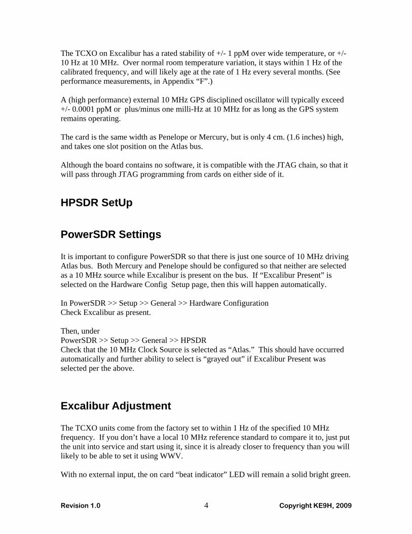
Appendix "A" contains the schematic and Board Top View, showing all part locations. This Board Top View should be used as the master reference for all part locations. Observe the silkscreen errata for Resistors R08 and R11. Appendix "E" contains the instructions for winding the toroid.
Checkout prior to first power application. A convenient “Ground” connection is the shield of the LOWER (Output) BNC connector, or the lower pin of J3. (The shield of the upper BNC “floats.”) The unit draws power from both the Atlas +12 Volt and +5 Volt. So check for no shorts to ground on Atlas +5 Volts, the extreme left pins on the Atlas Connector, C32/B32/A32. Other than a brief capacitor charging, I show open with a digital Ohm meter. Check for no shorts from Atlas +12 Volts to ground, the extreme right pins on the Atlas connector C1/B1/A1. Other than a brief capacitor charging, I show open on a digital Ohm meter. There are three labeled test points for the internal voltages, towards the left center of the board. Without power applied, but measuring to ground with a digital Ohm meter… For the +6V test point, I show 2.4 K to ground. For the +5V test point, I show 4.1 K to ground. For the +3.3V test point, I show 94K to ground. If you don’t see any shorts and your readings are reasonable, plug your board into the Atlas bus and power it up. With no external input, the on card “beat indicator” LED will show a solid bright green.

Revision 1.0 Copyright KE9H, 2009
Appendix "A"
Schematic, Board Top View and
PCB Silkscreen Errata

GND
GND GND
3.3K
6.8K
100
0.1u
F
GND
10
22
22
22
270
3.3K
6.8K
0.1uF
TC1-1T
0.1uF
50
CXOH20
+12V
+5V
1.8K
1K
GND
0.1uF
GND
0.1uF
GND
GND
330
200
GND
0.1uF
GND
6874AC04D
GND
+3.3V
+6V
+5V/1
0
0.1uF
DUAL-LED
+3.3V
GND
470pF 560pF
768nH
0.1uF
0.1uF
100K
B16
A1A2A3A4A5A6A7A8A9A10A11A12A13A14A15A16A17A18A19A20A21A22A23A24A25A26A27A28A29A30A31A32
B1B2B3B4B5B6B7B8B9B10B11B12B13B14B15
B17B18B19B20B21B22B23B24B25B26B27B28B29B30B31B32
C1C2C3C4C5C6C7C8C9C10C11C12C13C14C15C16C17C18C19C20C21C22C23C24C25C26C27C28C29C30C31C32
R2
R3
R4
C5
R12
R14
R15
R16
R7
R6
R5
C7
321 6
4
T1
C1
R1
12
J1
12
J3
43
2
5
1
X3
123
J2
Q1 Q2
R10
R9
C9
C3
R18
R13
C11
R8
X1
3 4U1B
5 6U1C
9 8U1D
11 10U1E
13 12U1F
1 2
147
U1A
R17
C10
PCP 1
PC1 2COMPIN3
VCOOUT4
INH5
C1A6
C1B7 VCOIN 9
PC2 13
R111
R212
PC3 15
SIGIN14
DEMOUT 10
VD
D16
GN
D8
U2
12
34
D1+6V
+3.3V
TP1
TP2
TP3
TP4
+5V
C8 C6L1
C4
C2
R11
HARTING_DIN96
GND
VCC
OUT
NC
GR
N
RE
D
To Atlas C16
Excalibur
Copyright KE9H 2009
TERM
SOURCESELECT
10 MHz OUT
SYNC
2N3906
0.1 to 1.5 V RMS
JTA
G
74HC4046
10 MHz INEXTERNAL
11 OCT 2009
EXT
TCXO
Version 1.3
ATLAS BUS
10 MHz

0.1uF2.2uF
+12V
0.1uF 0.1uF
0.1uF 0.1uF
GND
GND
GND
+5V
GND
+6V
+3.3VLP2985
10uF
10uF
0.01uFGND
+5V/1
C18C12
8
4
2 3 6 7
5
1
U4
8
4
2 3 6 75
1
U5
C20 C13
C19 C14
IN1
GN
D2
ON/~OFF3
BY
P4
OUT 5
U3
C17
C16
C15
Vin Vout
GNDNC NC
Vin Vout
GNDNC NC
3.3 Volts
L78L05_D
L78L06_D+6 Volts
+5 VoltsExcalibur
Copyright KE9H 2009
11 OCT 2009
Version 1.3

A1
B1
C1
B32
C32
A32
R11

A1
B1
C1
B32
C32
A32
R11

Revision 1.0 Copyright KE9H, 2009
PCB Silkscreen Errata There was a last minute change that didn’t update the silkscreen properly. See below for the proper location of R11 and R08. The board layout on the previous page is correct.

Revision 1.0 Copyright KE9H, 2009
Appendix "B"
Comments on Surface Mount assembly This appendix is not intended as a tutorial on surface mount soldering, but to give a few highlights. You can find many tutorials on hand soldering SMT components on-line, particularly on YouTube. This product has about 46 surface mount components, generally using the largest size available, that should make this a good choice for a first kit using surface mount assembly, by hand. Although it is possible to oven reflow, hot air reflow or hot plate reflow a surface mount PCB, it is not necessary for building this board, and basic hand assembly and soldering will work fine. Primary tools will be a desk mount lighted magnifying lens, a grounded fine point soldering iron, preferably temperature controlled, and a pair of curved point metal tweezers. An antistatic work mat with wrist strap is appropriate. A flux pen is helpful when soldering ICs, as is small diameter solder with a rosin core, and solderwick for picking up any excess solder. Generally, the process for a capacitor or resistor is to put a small dot of solder on ONE of the pads the part is going to be soldered to. Then, holding the part in the tweezers, hold it in position, and touch the tip of the iron to the solder dot, allowing it to melt and wet the end of the part. Then, using the tip of the tweezer to lightly push down on the center of the part melt the solder again, and the part will "click" down flat against the board. If the part is in the final desired position, melt a tiny bit of solder and fresh flux on the other end of the part, allowing the solder to flow under the end of the part. If you have a choice as to which end of the part to solder first, the end that is NOT grounded will be easier. Even though this board incorporates thermal reliefs (thermals) on all ground pads, the grounded end will still take more heat to solder than the other end. For an IC, if you have a flux pen, put a little flux on all PCB pads. Then choose one pad, at a corner, to put a small dot of solder upon. Holding the IC in position with the tweezers, using the iron, melt and solder the one corner pin. If necessary, using the tweezers, and re-melting the solder on the one pin, re-position the IC until it is centered on all pads. Then go to the pin diagonally across the IC and solder it down. If necessary, press down lightly on the center of the IC while re-melting those first two pins, so that all pins are flat against their respective pads. Then work your way around the IC soldering

Revision 1.0 Copyright KE9H, 2009
down all pins. If you have a solder short between adjacent pins, remove any excess solder with “solder wick.” For final inspection, a "Jewelers eye loupe" of approximately 4x power is a great aid. Loupes manufactured in Asia are available on eBay or similar sources for a few dollars.

Revision 1.0 Copyright KE9H, 2009
Appendix "C"
Bill of Materials

Excalibur Bill of Materials Version 10/11/2009
Footprint/Part Value Description Package Manu Part No. Vendor Part No. Notes
C01 0.1uF Chip Cap C1206 C1206 Kemet C1206C104K3RACTU Mouser 80-C1206C104K3RC02 0.1uF Chip Cap C1206 C1206 Kemet C1206C104K3RACTU Mouser 80-C1206C104K3RC03 0.1uF Chip Cap C1206 C1206 Kemet C1206C104K3RACTU Mouser 80-C1206C104K3RC04 0.1uF Chip Cap C1206 C1206 Kemet C1206C104K3RACTU Mouser 80-C1206C104K3RC05 0.1uF Chip Cap C1206 C1206 Kemet C1206C104K3RACTU Mouser 80-C1206C104K3RC06 560pF Chip Cap C1206 C1206 Kemet C1206C561J5GACTU Mouser 80-C1206C561J5G Must be NPO or C0GC07 0.1uF Chip Cap C1206 C1206 Kemet C1206C104K3RACTU Mouser 80-C1206C104K3RC08 470pF Chip Cap C1206 C1206 Kemet C1206C471J5GACTU Mouser 80-C1206C471J5G Must be NPO or C0GC09 0.1uF Chip Cap C1206 C1206 Kemet C1206C104K3RACTU Mouser 80-C1206C104K3RC10 0.1uF Chip Cap C1206 C1206 Kemet C1206C104K3RACTU Mouser 80-C1206C104K3RC11 0.1uF Chip Cap C1206 C1206 Kemet C1206C104K3RACTU Mouser 80-C1206C104K3RC12 2.2uF Chip Cap C1206 C1206 Kemet C1206C225K3RACTU Mouser 80-C1206C225K3RC13 0.1uF Chip Cap C1206 C1206 Kemet C1206C104K3RACTU Mouser 80-C1206C104K3RC14 0.1uF Chip Cap C1206 C1206 Kemet C1206C104K3RACTU Mouser 80-C1206C104K3RC15 0.01uF Chip Cap C1206 C1206 Kemet C1206C103K3RACTU Mouser 80-C1206C103K3RC16 10uF Tantalum A/3216-18R Vishay 293D106X9016A2TE3 Mouser 74-293D106X9016A2TE3C17 10uF Tantalum A/3216-18R Vishay 293D106X9016A2TE3 Mouser 74-293D106X9016A2TE3C18 0.1uF Chip Cap C1206 C1206 Kemet C1206C104K3RACTU Mouser 80-C1206C104K3RC19 0.1uF Chip Cap C1206 C1206 Kemet C1206C104K3RACTU Mouser 80-C1206C104K3RC20 0.1uF Chip Cap C1206 C1206 Kemet C1206C104K3RACTU Mouser 80-C1206C104K3R
D1 RED-GRN DUAL-LED LED-DUAL Lite-On LTST-C155KGJRKT Mouser 859-LTST-C155KGJRKT
J1 MA02 MA02 02PA 3M 2340-6111TG Mouser 517-6111-TG 40 pin breakaway header, use 2 pinsJ2 MA03-1 MA03-1 MA03-1 Use 3 pins from header for J1J3 MA02 MA02 02PA Use 2 pins from header for J1
L1 768nH T37-1W T37-1W Micrometals T37-6 Amidon T37-6 15 Turns #24 wire
P1 DIN96 Connector HARDING_DIN96 HARTING 09 03 196 6921 Mouser 617-09-03-196-6921
Q1 2N3906 PNP Transistor SOT23 Fairchild MMBT3906 Mouser 512-MMBT3906Q2 2N3906 PNP Transistor SOT23 Fairchild MMBT3906 Mouser 512-MMBT3906
R01 50 Chip Res R1206 R1206 Xicon 263-50-RC Mouser 263-50-RCR02 3.3K Chip Res R1206 R1206 Xicon 263-3.3K-RC Mouser 263-3.3K-RCR03 6.8K Chip Res R1206 R1206 Xicon 263-6.8K-RC Mouser 263-6.8K-RCR04 100 Chip Res R1206 R1206 Xicon 263-100-RC Mouser 263-100-RCR05 6.8K Chip Res R1206 R1206 Xicon 263-6.8K-RC Mouser 263-6.8K-RCR06 3.3K Chip Res R1206 R1206 Xicon 263-3.3K-RC Mouser 263-3.3K-RCR07 270 Chip Res R1206 R1206 Xicon 263-270-RC Mouser 263-270-RC

R08 68 Chip Res R1206 R1206 Xicon 263-68-RC Mouser 263-68-RCR09 1K Chip Res R1206 R1206 Xicon 263-1K-RC Mouser 263-1K-RCR10 1.8K Chip Res R1206 R1206 Xicon 263-1.8K-RC Mouser 263-1.8K-RCR11 100K Chip Res R1206 R1206 Xicon 263-100K-RC Mouser 263-100K-RCR12 10 Chip Res R1206 R1206 Xicon 263-10-RC Mouser 263-10-RCR13 200 Chip Res R1206 R1206 Xicon 263-200-RC Mouser 263-200-RCR14 22 Chip Res R1206 R1206 Xicon 263-22-RC Mouser 263-22-RCR15 22 Chip Res R1206 R1206 Xicon 263-22-RC Mouser 263-22-RCR16 22 Chip Res R1206 R1206 Xicon 263-22-RC Mouser 263-22-RCR17 0 Chip Res R1206 R1206 Xicon 263-0-RC Mouser 263-0-RCR18 330 Chip Res R1206 R1206 Xicon 263-330-RC Mouser 263-330-RC
T1 TC1-1T TC1-1T AT224 Minicircuits TC1-1T Minicircuits TC1-1T
U1 74AC04D 74AC04D SO14 TI SN74AC04D Mouser 595-SN74AC04DU2 74HC4046A 74HC4046A SO16 TI CD74HC4046AM96 Mouser 595-CD74HC4046AM96U3 3.3V LP2985 SOT23-5 TI LP2985-33DBVR Mouser 595-LP2985-33DBVRU4 6V L78L06_D SO08 STM L78L06ACD13TR Mouser 511-L78L06ACD-TRU5 5V L78L05_D SO08 ON MC78L05ACDG Mouser 863-MC78L05ACDG
X1 BNC - RA Connector SD-73100-FLT Molex 73100-0105 Mouser 538-73100-0105X2 BNC - RA Connector SD-73100 Molex 73100-0105 Mouser 538-73100-0105
X3 10.000 MHz CXOH20 CXOH20 Crystek CXOH20-BP-10.000 Mouser 549-CXOH20-BP-10
JC Jumper Clips Bergcon 68786-102LF Mouser 649-68786-102LF 2 each required
PCB Excalibur- Ver 1.3

Revision 1.0 Copyright KE9H, 2009
Appendix "D"
BOM Special Sort - Recommended Assembly Order

Excalibur Bill of Materials Version 10/11/2009
SPECIAL SORT FOR RECOMMENDED ASSEMBLY ORDER
Footprint/Part Value Description Package Manu Part No. Vendor Part No. Notes
C01 0.1uF Chip Cap C1206 C1206 Kemet C1206C104K3RACTU Mouser 80-C1206C104K3RC02 0.1uF Chip Cap C1206 C1206 Kemet C1206C104K3RACTU Mouser 80-C1206C104K3RC03 0.1uF Chip Cap C1206 C1206 Kemet C1206C104K3RACTU Mouser 80-C1206C104K3RC04 0.1uF Chip Cap C1206 C1206 Kemet C1206C104K3RACTU Mouser 80-C1206C104K3RC05 0.1uF Chip Cap C1206 C1206 Kemet C1206C104K3RACTU Mouser 80-C1206C104K3RC07 0.1uF Chip Cap C1206 C1206 Kemet C1206C104K3RACTU Mouser 80-C1206C104K3RC09 0.1uF Chip Cap C1206 C1206 Kemet C1206C104K3RACTU Mouser 80-C1206C104K3RC10 0.1uF Chip Cap C1206 C1206 Kemet C1206C104K3RACTU Mouser 80-C1206C104K3RC11 0.1uF Chip Cap C1206 C1206 Kemet C1206C104K3RACTU Mouser 80-C1206C104K3RC13 0.1uF Chip Cap C1206 C1206 Kemet C1206C104K3RACTU Mouser 80-C1206C104K3RC14 0.1uF Chip Cap C1206 C1206 Kemet C1206C104K3RACTU Mouser 80-C1206C104K3RC18 0.1uF Chip Cap C1206 C1206 Kemet C1206C104K3RACTU Mouser 80-C1206C104K3RC19 0.1uF Chip Cap C1206 C1206 Kemet C1206C104K3RACTU Mouser 80-C1206C104K3RC20 0.1uF Chip Cap C1206 C1206 Kemet C1206C104K3RACTU Mouser 80-C1206C104K3R
C06 560pF Chip Cap C1206 C1206 Kemet C1206C561J5GACTU Mouser 80-C1206C561J5G Must be NPO or C0GC08 470pF Chip Cap C1206 C1206 Kemet C1206C471J5GACTU Mouser 80-C1206C471J5G Must be NPO or C0GC12 2.2uF Chip Cap C1206 C1206 Kemet C1206C225K3RACTU Mouser 80-C1206C225K3RC15 0.01uF Chip Cap C1206 C1206 Kemet C1206C103K3RACTU Mouser 80-C1206C103K3R
C16 10uF Tantalum A/3216-18R Vishay 293D106X9016A2TE3 Mouser 74-293D106X9016A2TE3 Observe PolarityC17 10uF Tantalum A/3216-18R Vishay 293D106X9016A2TE3 Mouser 74-293D106X9016A2TE3 Observe Polarity
R01 50 Chip Res R1206 R1206 Xicon 263-50-RC Mouser 263-50-RCR02 3.3K Chip Res R1206 R1206 Xicon 263-3.3K-RC Mouser 263-3.3K-RCR03 6.8K Chip Res R1206 R1206 Xicon 263-6.8K-RC Mouser 263-6.8K-RCR04 100 Chip Res R1206 R1206 Xicon 263-100-RC Mouser 263-100-RCR05 6.8K Chip Res R1206 R1206 Xicon 263-6.8K-RC Mouser 263-6.8K-RCR06 3.3K Chip Res R1206 R1206 Xicon 263-3.3K-RC Mouser 263-3.3K-RCR07 270 Chip Res R1206 R1206 Xicon 263-270-RC Mouser 263-270-RCR08 68 Chip Res R1206 R1206 Xicon 263-68-RC Mouser 263-68-RCR09 1K Chip Res R1206 R1206 Xicon 263-1K-RC Mouser 263-1K-RCR10 1.8K Chip Res R1206 R1206 Xicon 263-1.8K-RC Mouser 263-1.8K-RCR11 100K Chip Res R1206 R1206 Xicon 263-100K-RC Mouser 263-100K-RCR12 10 Chip Res R1206 R1206 Xicon 263-10-RC Mouser 263-10-RCR13 200 Chip Res R1206 R1206 Xicon 263-200-RC Mouser 263-200-RCR14 22 Chip Res R1206 R1206 Xicon 263-22-RC Mouser 263-22-RCR15 22 Chip Res R1206 R1206 Xicon 263-22-RC Mouser 263-22-RCR16 22 Chip Res R1206 R1206 Xicon 263-22-RC Mouser 263-22-RCR17 0 Chip Res R1206 R1206 Xicon 263-0-RC Mouser 263-0-RCR18 330 Chip Res R1206 R1206 Xicon 263-330-RC Mouser 263-330-RC

D1 RED-GRN DUAL-LED LED-DUAL Lite-On LTST-C155KGJRKT Mouser 859-LTST-C155KGJRKT Observe Polarity/Position
Q1 2N3906 PNP Transistor SOT23 Fairchild MMBT3906 Mouser 512-MMBT3906Q2 2N3906 PNP Transistor SOT23 Fairchild MMBT3906 Mouser 512-MMBT3906
U1 74AC04D 74AC04D SO14 TI SN74AC04D Mouser 595-SN74AC04D Observe Position DotU2 74HC4046A 74HC4046A SO16 TI CD74HC4046AM96 Mouser 595-CD74HC4046AM96 Observe Position DotU3 3.3V LP2985 SOT23-5 TI LP2985-33DBVR Mouser 595-LP2985-33DBVR Observe Position DotU4 6V L78L06_D SO08 STM L78L06ACD13TR Mouser 511-L78L06ACD-TR Observe Position DotU5 5V L78L05_D SO08 ON MC78L05ACDG Mouser 863-MC78L05ACDG Observe Position Dot
T1 TC1-1T TC1-1T AT224 Minicircuits TC1-1T Minicircuits TC1-1T
P1 DIN96 Connector HARDING_DIN96 HARTING 09 03 196 6921 Mouser 617-09-03-196-6921
J1 MA02 MA02 02PA 3M 2340-6111TG Mouser 517-6111-TG 40 pin breakaway header, use 2 pinsJ2 MA03-1 MA03-1 MA03-1 Use 3 pins from header for J1J3 MA02 MA02 02PA Use 2 pins from header for J1
X1 BNC - RA Connector SD-73100-FLT Molex 73100-0105 Mouser 538-73100-0105X2 BNC - RA Connector SD-73100 Molex 73100-0105 Mouser 538-73100-0105
L1 768nH T37-1W T37-1W Micrometals T37-6 Amidon T37-6 15 Turns #24 wire
X3 10.000 MHz CXOH20 CXOH20 Crystek CXOH20-BP-10.000 Mouser 549-CXOH20-BP-10
Revision 1.0 Copyright KE9H, 2009
Appendix "E"
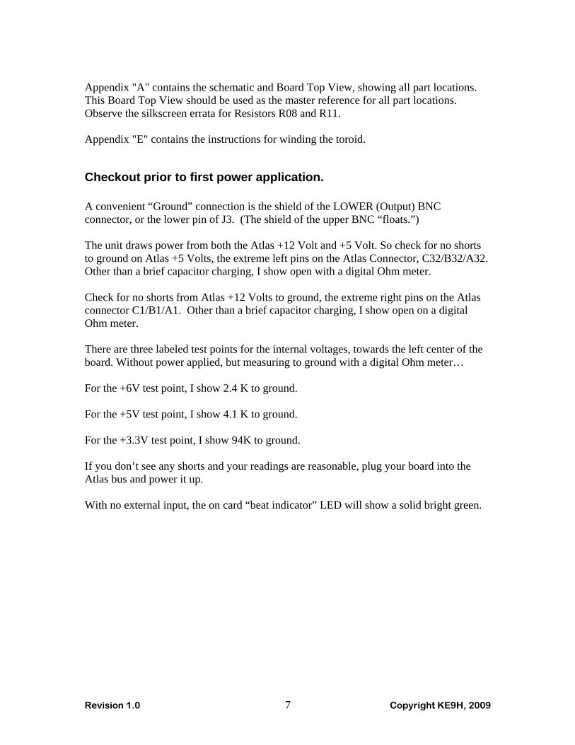
Instructions for Winding the Toroid Note : When counting turns of wire on a toroid, the definition of a turn is a pass through the center of the toroid. So, a two turn toroid, would have the wire passing through the center hole two times.
FINISHED TOROID
L1 is constructed using an Amidon/MicroMetals T37-6 toroid core, wound with 15 turns of number 24 wire. The direction of the winding is important, so that the leads, when they exit the toroid, match the hole pattern in the PC board.

Revision 1.0 Copyright KE9H, 2009
STARTING THE WINDING
Start the winding with the wire positioned as shown. Proceed winding until there are fifteen turns of wire on the toroid. The completed, the toroid should look as shown at the front of this section. Check that the top and bottom wire exit as shown. The turns should be equally spaced around the perimeter of the toroid. Cut the leads to about one half inch long (1.3 cm). Strip and tin the wire from the edge of the toroid to the end of the lead. The insulation on the wire provided with this kit will break down and allow solder to tin the wire, with a soldering iron temperature of 825 degrees F (440 degrees C). You can speed up the process by exposing the copper towards the tip of the wire, to allow faster heat transfer into the copper, since the coating is a thermal insulator. Just be sure not to nick the wire close to where it will pass through the PC board.

Revision 1.0 Copyright KE9H, 2009
Appendix "F"
Performance Measurements

Revision 1.0 Copyright KE9H, 2009
From Joe, K5SO ---
Here is a JPEG image of my measurement results of Excalibur's TCXO output frequency over a 3-day period. Measurements were taken every 100 seconds with a precision of 1 milli-Hz using the equipment indicated in the image file. The Excalibur board was open (in an Antec NSK2480 enclosure with the top off) to the shack environment. Daily ambient shack temperature variations were over the range 65F to 79F; I did not record the precise time-temperature profile of the shack during these measurements. As you can see from the plot, the Excalibur TCXO stayed at 10 MHz within about +/- 1 Hz during the entire measurement period.
73, Joe K5SO

Revision 1.0 Copyright KE9H, 2009
John Ackermann, N8UR did some very detailed testing of stability and phase noise performance. Refer to his website at http://www.febo.com/pages/excalibur for a lot more detail of his testing methodology, results, and comments on the TCXO performance.