Excalibur ARM-Based Hardware Design Tutorial User Guide · PDF fileBold italic type Book...
66
A-MNL_ARMTUTORIAL-1.3 Hardware Design Tutorial Excalibur ARM-Based 101 Innovation Drive San Jose, CA 95134 (408) 544-7000 http://www.altera.com User Guide July 2001 Version 1.3
Transcript of Excalibur ARM-Based Hardware Design Tutorial User Guide · PDF fileBold italic type Book...

A-MNL_ARMTUTORIAL-1.3
Hardware Design Tutorial
Excalibur ARM-Based
101 Innovation DriveSan Jose, CA 95134(408) 544-7000http://www.altera.com
User GuideJuly 2001
Version 1.3

ii Altera Corporation
Excalibur ARM-Based Hardware Design Tutorial User Guide
Altera, APEX, Excalibur, FineLine BGA, MegaCore, MegaWizard, NativeLink, Quartus, and SignalTap are trademarks and/orservice marks of Altera Corporation in the United States and other countries. Altera acknowledges the trademarks of otherorganizations for their respective products or services mentioned in this document, including the following: AMBA is a trademarkand ARM, Thumb and the ARM-Powered logo are registered trademarks of ARM Limited. Verilog is a registered trademark ofCadence Design Systems, Incorporated. ModelSim is a trademark of Model Technologies. Altera products are protected undernumerous U.S. and foreign patents and pending applications, maskwork rights, and copyrights. Altera warrants performance ofits semiconductor products to current specifications in accordance with Altera’s standard warranty, but reservesthe right to make changes to any products and services at any time without notice. Altera assumes noresponsibility or liability arising out of the application or use of any information, product, or service describedherein except as expressly agreed to in writing by Altera Corporation. Altera customers are advised to obtain thelatest version of device specifications before relying on any published information and before placing orders forproducts or services.
Copyright 2001 Altera Corporation. All rights reserved.

User Guide
About this User Guide
This user guide provides comprehensive information about the Altera® Excalibur™ ARM®-based hardware design tutorial.
Table 1 shows the user guide revision history.
How to Find Information
� The Adobe Acrobat Find feature allows you to search the contents of a PDF file. Click on the binoculars icon in the top toolbar to open the Find dialog box.
� Bookmarks serve as an additional table of contents.� Thumbnail icons, which provide miniature previews of each page,
provide a link to the pages.� Numerous links, shown in green text, allow you to jump to related
information.
Table 1. Revision History
Revision Date Description
1.0 Jan 20th 2001 Initial release
1.1 April 4th 2001 Minor amendments; additional full-stripe model tutorial
1.2 June 11th 2001 Minor amendments; new Appendix D
1.3 July 5th 2001 New steps for using Quartus II software mode on PCs and Unix
Altera Corporation iii

About this User Guide Excalibur ARM-Based Hardware Design Tutorial User Guide
How to Contact Altera
For the most up-to-date information about Altera products, go to the Altera world-wide web site at http://www.altera.com.
For additional information about Altera products, consult the sources shown in Table 2.
Note:(1) You can also contact your local Altera sales office or sales representative.
Table 2. How to Contact Altera
Information Type Access USA & Canada All Other Locations
Altera Literature Services
Electronic mail [email protected] (1) [email protected] (1)
Non-technical customer service
Telephone hotline (800) SOS-EPLD (408) 544-7000 (7:30 a.m. to 5:30 p.m. Pacific Time)
Fax (408) 544-7606 (408) 544-7606
Technical support Telephone hotline (800) 800-EPLD(6:00 a.m. to 6:00 p.m. Pacific Time)
(408) 544-7000 (1)(7:30 a.m. to 5:30 p.m. Pacific Time)
Fax (408) 544-6401 (408) 544-6401 (1)
Electronic mail [email protected] [email protected]
FTP site ftp.altera.com ftp.altera.com
General product information
Telephone (408) 544-7104 (408) 544-7104 (1)
World-wide web site http://www.altera.com http://www.altera.com
iv Altera Corporation
Excalibur ARM-Based Hardware Design Tutorial User Guide About this User Guide
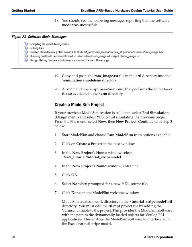
Typographic Conventions
The Excalibur ARM-Based Hardware Design Tutorial User Guide uses the typographic conventions shown in Table 3.
Table 3. Conventions
Visual Cue Meaning
Bold Type with Initial Capital Letters
Command names, dialog box titles, checkbox options, and dialog box options are shown in bold, initial capital letters. Example: Save As dialog box.
bold type External timing parameters, directory names, project names, disk drive names, filenames, filename extensions, and software utility names are shown in bold type. Examples: fMAX, \maxplus2 directory, d: drive, chiptrip.gdf file.
Bold italic type Book titles are shown in bold italic type with initial capital letters. Example: 1999 Device Data Book.
Italic Type with Initial Capital Letters
Document titles are shown in italic type with initial capital letters. Example: AN 75 (High-Speed Board Design).
Italic type Internal timing parameters and variables are shown in italic type. Examples: tPIA, n + 1.Variable names are enclosed in angle brackets (< >) and shown in italic type. Example: <file name>, <project name>.pof file.
Initial Capital Letters Keyboard keys and menu names are shown with initial capital letters. Examples: Delete key, the Options menu.
“Subheading Title” References to sections within a document and titles of Quartus and MAX+PLUS II Help topics are shown in quotation marks. Example: “Configuring a FLEX 10K or FLEX 8000 Device with the BitBlaster™ Download Cable.”
Courier type Signal and port names are shown in lowercase Courier type. Examples: data1, tdi, input. Active-low signals are denoted by suffix _n, e.g., reset_n.
Anything that must be typed exactly as it appears is shown in Courier type. For example: c:\max2work\tutorial\chiptrip.gdf. Also, sections of an actual file, such as a Report File, references to parts of files (e.g., the AHDL keyword SUBDESIGN), as well as logic function names (e.g., TRI) are shown in Courier.
1., 2., 3., and a., b., c.,... Numbered steps are used in a list of items when the sequence of the items is important, such as the steps listed in a procedure.
� Bullets are used in a list of items when the sequence of the items is not important.
� The checkmark indicates a procedure that consists of one step only.
� The hand points to information that requires special attention.
� The angled arrow indicates you should press the Enter key.
� The feet direct you to more information on a particular topic.
Altera Corporation v

Notes:

Contents
User Guide
About this User Guide ..............................................................................iiiHow to Find Information ............................................................................................................iiiHow to Contact Altera .................................................................................................................. ivTypographic Conventions ............................................................................................................. v
Getting Started .......................................................................................9Tutorial Files ...................................................................................................................................11Creating a Design ...........................................................................................................................12
Creating a Quartus II Project ................................................................................................14Creating a New Block Design File .......................................................................................14Creating an ARM-Based Excalibur MegaFunction ...........................................................15Instantiating arm_processor .................................................................................................21Synthesizing Pld_slave in the LeonardoSpectrum Software ...........................................22Creating a .bsf for Pld_slave .................................................................................................23Instantiating Pld_slave ..........................................................................................................23
Verification using the Excalibur Bus Transactor .......................................................................26Behavioral Simulation ...........................................................................................................26Generating .dat Files for Simulation ...................................................................................27Creating a ModelSim Project ................................................................................................28Compiling the Design Files ..................................................................................................28Simulating ...............................................................................................................................29
Compilation ....................................................................................................................................30Compiler Settings ...................................................................................................................30Compiling the Design ............................................................................................................32
Timing Simulation .........................................................................................................................32Generating DAT files for Simulation ..................................................................................32Creating a ModelSim Project ................................................................................................33Compiling the Design Files ..................................................................................................33Simulating ...............................................................................................................................34
Verification using the Full-Stripe Model ....................................................................................35Editing the Design in Quartus II ..................................................................................................35
Creating a Quartus II Project ................................................................................................35Modify the arm_top_ebi Block Design File ........................................................................36Instantiating the arm_processor_ebi ...................................................................................41
RTL Simulation using the Stripe Model .....................................................................................43Build Software Code ..............................................................................................................44Create a ModelSim Project ....................................................................................................50Compile the Design Files ......................................................................................................51Compile the Testbench and Model Files ............................................................................51Simulate ...................................................................................................................................52
Altera Corporation vii

Contents
Compilation ............................................................................................................................53Compiling the Design ............................................................................................................54Timing Simulation using the Full Stripe Model ................................................................54Compile the Design Files ......................................................................................................55Compile the Testbench and Model Files ............................................................................55Simulate ...................................................................................................................................56Viewing the Signals ...............................................................................................................56
Appendix A .......................................................................................... 57Appendix B .......................................................................................... 61Appendix C .......................................................................................... 63Appendix D ......................................................................................... 65
Using the VHDL Bus Functional Model .....................................................................................65Behavioral Simulation ...........................................................................................................65Timing Simulation .................................................................................................................65
Using the VHDL Stripe Model .....................................................................................................65Behavioral Simulation ...........................................................................................................66Timing Simulation .................................................................................................................66
viii Altera Corporation

User Guide
1
Getting StartedGetting Started
The Excalibur™ solutions ARM®-based embedded processor PLDs hardware design tutorial user guide walks you through the creation and simulation of an ARM-based processor PLD system hardware design. The design targets an Altera® EPXA 10 device (for more information see the Excalibur ARM-Based Embedded Processor PLDs Hardware Reference Manual). The design uses the Altera ARM-based processor core and the AMBA high-performance bus (AHB) to write to a memory-mapped slave peripheral in the PLD portion of the device. The slave peripheral is an arithmetic unit that performs a function based on data received from the ARM-based processor core. The tutorial shows you how to perform behavioral and timing simulation using a bus functional model and a complete cycle-accurate stripe model. The Excalibur bus transactor, the bus functional model provided in the Quartus™ II software, is used along with the ModelSim software to simulate the design and verify the AHB compatibility of the slave peripheral. The full stripe model is also used with the ModelSim software to simulate the entire stripe and the slave peripheral logic.
This walkthrough involves the following steps:
1. Installing the tutorial
2. Creating a design
3. Behavioral simulation using the bus functional model
4. Compiling the design in the Quartus II software
5. Performing timing simulation using the bus functional model
6. Editing the design to allow simulation with software
7. RTL simulation using the full-stripe model
8. Compiling the new design in the Quartus II software
9. Performing timing simulation using the full-stripe model
Altera Corporation 9

Getting Started Excalibur ARM-Based Hardware Design Tutorial User Guide
The instructions assume that:
� Your PC has the following software installed:– The Quartus II software, version 1.1– The Altera ARM Developer Suite (ADS) version 1.1– Exemplar LeonardoSpectrum software, version 2001.1a or
above, licensed for Verilog HDL– Model Technology ModelSim SE software (version 5.3d or
above)� You are familiar with the Quartus II software� You are familiar with the ARM-based processor PLD and its AHB
architecture
Excalibur designs can be implemented in VHDL, Verilog HDL, AHDL, and graphical format. This walkthrough uses graphical entry. For information on simulating Excalibur designs in VHDL, see Appendix D.
� When using a third-party synthesis tool, the ARM-based processor core can beblack-boxed in the HDL file. See ATLAS solutions at http://www.altera.com for guidelines on black-boxing functions in various EDA tools.
10 Altera Corporation

Excalibur ARM-Based Hardware Design Tutorial User Guide Getting Started
1
Getting Started
Tutorial Files The tutorial files are installed in C:\altera\excalibur\arm-based\example_designs\arm_tutorial by default. Tables 1 and 2 show the folder structure that is created.
Note:(1) The slave peripheral design comprises the following lower-level Verilog HDL files: ahb_slave_sm.v, alu.v,
regfile.v, and wait_state_gen.v.
Table 1. Folder Structure—First Half of the Tutorial
Folder Description
\arm_tutorial
tutorial_bfm Contains the Verilog HDL files for the first half of the ttutorial.
pld_slave.v The slave peripheral design. (1)
ahb_slave_sm.v The AHB interface state machine that contains all of the logic necessary for the ARM-based processor core to interface with a slave in the PLD part of the ARM-based device through the AHB2PLD bridge.
alu.v The arithmetic unit that performs the calculations on the two operands.
regfile.v Contains the operand, operator, and data registers.
wait_state_gen.v Logic that ensures the current result is output.
ahb_slave_include.v Include file that defines the required parameters.
behavioral Contains files for behavioral simulation.
input.dat Command language file that contains bus transaction commands.
slavememory.cfg.dat Memory configuration file required when using the Excalibur bus functional model.
sim_arm_top.do ModelSim command file that contains stimulus for simulation.
wave.do ModelSim waveform command file
simulation
modelsim Contains files for timing simulation.
sim_arm_top.do ModelSim command file that contains stimulus for simulation.
slavememory.cfg.dat Memory configuration file required when using the Excalibur bus functional model.
Altera Corporation 11

Getting Started Excalibur ARM-Based Hardware Design Tutorial User Guide
Creating a Design
This section walks you through creating an example of a design—arm_top.bdf (see Figure 1 on page 13).
This design includes the ARM-based processor core, arm_processor, and a memory-mapped slave peripheral, pld_slave. Pld_slave accepts two operands and an operator that tells it whether to add, subtract, or multiply the operands. The result is written to a location in a register file.
Figure 2 on page 13 shows a block design file representation of the pld_slave.
Table 2. Folder Structure—Second Half of the Tutorial
Folder Description
tutorial_stripemodel Contains the Verilog HDL files for the first half of the ttutorial.
arm_top_ebi.bdf Quartus II block design file template
pld_slave.v The slave peripheral design
pld_slave.bsf Slave peripheral block symbol file
ahb_slave_sm.v The AHB interface state machine that contains all of the logic necessary for the ARM-based processor core to interface with a slave in the PLD part of the ARM-based device through the AHB2PLD bridge
alu.v The arithmetic unit that performs the calculations on the two operands
regfile.v Contains the operand, operator, and data registers.
wait_state_gen.v Logic that ensures the current result is output.
ahb_slave_include.v Include file that defines the required parameters
asm Contains assembly code
tutorial_code.s Assembly code for arm_top design
asm2rom Command file utility that converts assembly to hex format
rtl Contains files for RTL simulation with the stripe model
arm_top_tb.v Test bench file
simple_rom.v ROM Verilog HDL model
compile_fullmodel.do ModelSim command file that compiles stripe model files
wave.do ModelSim waveform command file
edit_mpf.txt Text to be copied to ModelSIm project file
simulation
modelsim
compile_fullmodel.do ModelSim command file that compiles stripe model files.
edit_mpf.txt Text to be copied to ModelSim project file
arm_top_tb.v Test bench file.
simple_rom.v Verilog ROM model.
12 Altera Corporation

Excalibur ARM-Based Hardware Design Tutorial User Guide Getting Started
1
Getting Started
Figure 1. Arm_top.bdf
Figure 2. Pld_slave
Altera Corporation 13

Getting Started Excalibur ARM-Based Hardware Design Tutorial User Guide
Creating a design involves the following:
� Creating a new Quartus II project and a top-level block design file (.bdf). The .bdf contains arm_processor and pld_slave.
� Synthesizing pld_slave in the LeonardoSpectrum software and importing the EDIF output into the Quartus II software via a block symbol file (.bsf).
� Using the Quartus II software to place and route the top-level design see Compilation on page 30).
Creating a Quartus II Project
To create a new project, perform the following steps:
1. Open the Quartus II software.
2. Select New Project Wizard (File menu).
3. Browse to the \arm_tutorial\tutorial_bfm directory.
4. Type in arm_tutorial as the project name.
5. Type in arm_top as the top-level entity name.
6. Click Next.
7. Click Finish to create the project.
Creating a New Block Design File
To create the top-level design entity (arm_top.bdf) of the arm_tutorial project, perform the following steps:
1. Select New (File menu).
2. In the Design Files tab, select Block Diagram/Schematic File.
3. Click OK. A new Block Editor window appears.
4. Select Save As (File menu).
5. Specify \arm_tutorial\tutorial_bfm as the folder for saving the file.
6. In the File Name box, type in arm_top.bdf.
7. Ensure Add File to Current Project is turned on.
14 Altera Corporation

Excalibur ARM-Based Hardware Design Tutorial User Guide Getting Started
1
Getting Started
8. Click Save. This saves the file and adds it to the project.
Creating an ARM-Based Excalibur MegaFunction
This section creates and instantiates the ARM-Based Excalibur Megafunction into the top-level design file, arm_top.bdf using the MegaWizard Plug-In Manager.
Follow these steps to create the symbol:
1. Select MegaWizard Plug-In Manager (Tools menu).
2. Figure 3 shows the MegaWizard Plug-In Manager [page 1] dialog box; select Create a new custom megafunction variation.
Figure 3. MegaWizard Plug-In Manager: Page 1
3. Click Next.
4. Figure 4 on page 16 shows the MegaWizard Plug-In Manager [page 2a] dialog box; under Available Megafunctions, select ARM-based Excalibur.
Altera Corporation 15

Getting Started Excalibur ARM-Based Hardware Design Tutorial User Guide
Figure 4. MegaWizard Plug-In Manager: Page 2a
5. Select Verilog HDL as the type of output file you want to create
6. Type \arm_tutorial\tutorial_bfm\arm_processor as the output file name.
7. Click Next.
8. Figure 5 on page 17 shows the Megawizard Plug-In Manager – Excalibur [Page 3] dialog box; select Excalibur_ARM as the Excalibur family and EPXA10 as the available device.
16 Altera Corporation

Excalibur ARM-Based Hardware Design Tutorial User Guide Getting Started
1
Getting Started
Figure 5. MegaWizard Plug-In Manager: Page 3
9. Uncheck both options under Reset operation.
10. Select Little endian as the byte order.
11. Under the Reserve pins heading, ensure that the EBI (FLASH), SDRAM, UART and Trace options are left unchecked.
12. Click Next.
13. Figure 6 on page 18 shows the Megawizard Plug-In Manager – Excalibur [Page 4]; select only the STRIPE_TO_PLD bridge (Master Port) option under Bridges.
Altera Corporation 17

Getting Started Excalibur ARM-Based Hardware Design Tutorial User Guide
Figure 6. MegaWizard Plug-In Manager: Page 4
14. Uncheck both options under Interrupts.
15. Ensure that no boxes are checked under Trace/Debug.
16. Click Next.
17. Figure 7 on page 19 shows the Megawizard Plug-In Manager – Excalibur [Page 5]; type 33.0 MHz in the External clock reference frequency.
18 Altera Corporation

Excalibur ARM-Based Hardware Design Tutorial User Guide Getting Started
1
Getting Started
Figure 7. MegaWizard Plug-In Manager: Page 5
18. Under AHB1/AHB2 clock settings, select Bypass PLL1.
19. Under Select AHB1 frequency, type 16.5 MHz
20. Under Select AHB2 frequency, type 8.25 MHz.
21. Ensure that SDRAM clock settings are grayed out.
Altera Corporation 19

Getting Started Excalibur ARM-Based Hardware Design Tutorial User Guide
22. Select the checkbox Are you using a serial EEPROM configuration device?
23. Click Next.
24. Figure 8 shows the Megawizard Plug-In Manager – Excalibur [Page 6], type 7FFFC000 as the base address of the Registers region and select 16K as its size.
Figure 8. MegaWizard Plug-In Manager: Page 6
25. Select 16K as the size of PLD0 and type 10000000 as the base address.
20 Altera Corporation

Excalibur ARM-Based Hardware Design Tutorial User Guide Getting Started
1
Getting Started
26. Uncheck the Prefetch option for PLD0.
27. All other options should have the size of the regions set to off, except for the SDRAM and EBI peripherals, which should be grayed out.
28. Click Next.
29. The Megawizard Plug-In Manager –Excalibur [Page 7] appears, as shown in Figure 9. Click Finish to create the design files.
Figure 9. MegaWizard Plug-In Manager: Page 7
Instantiating arm_processor
Instantiate the arm_processor symbol into the top-level design file, arm_top.bdf, by performing the following steps:.
1. Select Symbol (Insert menu).
2. In the Symbol dialog box, in the Projects list, click the + icon to expand the project folder.
3. Select the arm_processor symbol.
4. Click OK.
5. An outline of the ARM core symbol is attached to the pointer.
6. Place the symbol by clicking on an empty space in the Block Editor window.
Altera Corporation 21

Getting Started Excalibur ARM-Based Hardware Design Tutorial User Guide
7. Select Save (File menu).
Synthesizing Pld_slave in the LeonardoSpectrum Software
The LeonardoSpectrum software synthesizes pld_slave.v into EDIF format before being included in a top-level design. To synthesize pld_slave.v using the LeonardoSpectrum software, perform the following steps:
1. Open the LeonardoSpectrum software.
2. Select New Project (File menu), to create a new project.
3. Check Flow Tabs (Tools Menu) to display the various settings tabs.
4. In the Technology tab, select Excalibur ARM as the device family, EPXA10F1020C as the device, and 1 as the speed grade.
5. Ensure the Map I/O Registers option is unchecked.
6. In the Input tab, click on the Working Directory icon and select \arm_tutorial\tutorial_bfm as your working directory.
7. Click on the Open Files icon and select pld_slave.v, alu.v, ahb_slave_sm.v, regfile.v, and wait_state_gen.v. Select multiple files by holding down the Ctrl key on your keyboard.
8. Click Open to include the files in the project.
9. In the Optimize tab, ensure the Add I/O Pads option is unchecked.
10. In the Output tab, specify pld_slave.edf as the output filename.
11. Click Apply.
12. Click Run Flow to begin synthesis.
� The LeonardoSpectrum software issues several messages that do not affect the synthesis results:
- ahb_slave_include.v”, line 73: Warning text macro (OPER) redefined - replace with new definition
- ahb_slave_include.v”, line 74: Warning text macro (RELOW) redefined - replace with new definition
- ahb_slave_include.v”, line 74: Warning text macro (REHIG) redefined - replace with new definition
22 Altera Corporation

Excalibur ARM-Based Hardware Design Tutorial User Guide Getting Started
1
Getting Started
13. When the synthesis is finished, select Save Project (File menu) and save as pld_slave.lsp.
14. The synthesis run results in the pld_slave.edf file. Close the LeonardoSpectrum software.
Creating a .bsf for Pld_slave
You must create a block symbol file (.bsf) representation of the .edf file generated by the LeonardoSpectrum software synthesis, before it can be included in the top-level Quartus II .bdf.
To create the .bsf file for pld_slave.edf, perform the following steps:
1. In Quartus II, open pld_slave.edf.
2. Select Create Symbol Files for Entities in Current File (Tools menu).
3. A dialog box appears, indicating that block symbol file creation was successful. Click OK.
4. Close the compilation report and pld_slave.edf windows.
pld_slave.bsf is available for instantiation in the top-level design file.
Instantiating Pld_slave
To instantiate pld_slave.bsf, into the top-level design file, arm_top.bdf, perform the following steps:
1. Select Symbol (Insert menu).
2. Expand the Project folder and select pld_slave.bsf.
3. Click OK.
4. Instantiate the symbol by clicking on an empty space in the .bdf.
To complete the top-level design, you must connect the signals between the blocks and also connect the necessary I/O pins to the input and output ports. To connect the signals, perform the following steps:
1. Click the Orthogonal Node Tool button on the toolbar.
Altera Corporation 23

Getting Started Excalibur ARM-Based Hardware Design Tutorial User Guide
2. Click the pin stub of the arm_processor node (see Table 3) to define the start of the node. Drag the pointer to draw a line that connects to the corresponding pld_slave node (see Table 3).
3. Repeat step 2 for each pair of signals (see Table 3).
You must instantiate input and output pins in the arm_top.bdf file.
To enter I/O pins, perform the following steps:
1. Click the Symbol Tool button on the Block Editor toolbar. The Symbol dialog box opens with the Repeat-insert mode option turned on.
� When the Repeat-insert mode option is on, an outline of the selected symbol remains attached to the cursor, regardless of how many times you click, which allows you to place multiple copies of the symbol. When you want to stop placing copies of a symbol, press Esc or choose Cancel (right mouse button pop-up menu).
2. In the Symbol dialog box, in the Libraries list, expand the d:\quartus\libraries folder, expand the primitives folder, and expand the pin folder.
3. In the pin folder, select the input primitive.
4. Click OK.
5. Click an empty space six times to insert a total of six input symbols on the left-hand side of the file. Press Esc.
Table 3. Nodes
Arm_processor Node Pld_slave Node
masterhwrite HWRITE
masterhaddr[31..0] HADDRESS[31..0]
masterhtrans[1..0] HTRANS[1..0]
masterhsize[1..0] HSIZE[1..0]
masterburst[2..0] HBURST[2..0]
masterhwdata[31..0] HWDATA[31..0]
masterhrdata[31..0] HRDATA[31..0]
masterhresp[1..0] HRESP[1..0]
masterhready HREADY
24 Altera Corporation

Excalibur ARM-Based Hardware Design Tutorial User Guide Getting Started
1
Getting Started
6. Repeat steps 1 to 5 to insert and position an output pin and a bidirectional pin in the file. Figure 1 shows the locations.
7. Name the pins by double clicking on them. Table 4 shows the input pin names; Table 5 shows the output and bidirectional pin names.
After entering the inputs and outputs, you must connect them to the appropriate ports on arm_processor, and pld_slave.
To connect the pins and primitives by drawing node and bus lines, perform the following steps:
1. Click the Orthogonal Node Tool button on the toolbar.
2. Click the pin stub of the HCLOCK input pin to define the start of the node, and then drag the pointer to draw a line that connects to the pin stub of the arm_processor masterhclk port. Draw another line to connect it to the HCLOCK port of pld_slave.
3. Repeat step 2 for each pair of signals (see Tables 4 and 5). The symbol where each node is located is specified in parentheses.
Table 4. Input Pin Names
Input Pin Name Connect To
HCLOCK masterhclk (arm_processor); HCLOCK (pld_slave)
HGRANT masterhgrant (arm_processor)
HSEL HSEL (pld_slave)
HRESETn HRESETn (pld_slave)
nPOR npor (arm_processor)
clk_ref clk_ref (arm_processor)
Table 5. Output and Bidirectional Pin Names
Output Pin Name Connect To
HR_DATA[31..0] HRDATA[31..0] (pld_slave)
nRESET nreset (arm_processor)
Altera Corporation 25

Getting Started Excalibur ARM-Based Hardware Design Tutorial User Guide
Verification using the Excalibur Bus Transactor
This section explains how to perform behavioral simulation and generate .dat files. It also tells you how to create a ModelSim project, compile the design files and simulate the model.
Behavioral Simulation
You can perform behavioral simulation on the design before performing compilation and place and route in the Quartus II software. You can create a top-level Verilog HDL file from your arm_top.bdf using the Create HDL File utility in the Quartus II software. You can use the resulting arm_top.v and lower level Verilog HDL files to simulate the ARM-based processor-PLD system in the ModelSim software. The Excalibur bus transactor supplies the .dat files required to simulate bus transactions.
� For more information on the Excalibur bus functional model, refer to the Excalibur Bus Functional Model User Guide, version 1.0.
To generate the arm_top.v file, perform the following steps:
1. Open arm_top.bdf in the Quartus II software.
2. Select Create HDL Design File for Current File (Tools menu).
3. Click Yes, if you are prompted to save changes to the file.
4. Select Verilog HDL in the Create HDL Design File for Current File box.
5. Click OK.
6. Click OK in the box indicating that the HDL file generation was successful.
7. Cut and paste the arm_top.v file from the \arm_tutorial\tutorial_bfm folder into the \arm_tutorial\tutorial_bfm\behavioral folder.
� Arm_top.v must not be left in the \arm_tutorial\tutorial_bfm folder, as it causes conflicts with arm_top.bdf in the Quartus II compilation section of this tutorial.
26 Altera Corporation

Excalibur ARM-Based Hardware Design Tutorial User Guide Getting Started
1
Getting Started
Generating .dat Files for Simulation
The Excalibur bus transactor is an executable that supports functional simulation of the ARM stripe master and slave ports. It accepts input.dat as its input and generates a mastercommands.dat file. The mastercommands.dat file is interpreted by alteramf.v or apex20ke_atoms.v to simulate read/write instructions issued to the PLD by the embedded processor via the STRIPE-to-PLD interface. The alt_exc_stripe_bfm simulation wrapper file calls the appropriate stripe module and simulation module containing the bus functional model description.
The input.dat file (see Appendix B for an example) specifies the bus transactions to be simulated. The first command idles the AHB system for four clock cycles. In the pld_slave, the register at address 4 is operand 1, the register at address 8 is operand 2, the operation to be done is stored at address 12, and the result is stored at address 16. An operation value of 5 specifies addition, 6 specifies subtraction, and 7 specifies multiplication. The next series of commands writes 10 to operand 1, 5 to operand 2, and 5 to the operation register. The expected result from the third command is to read the value 15 (0FH), the sum of operands 1 and 2, from the result register. The next series of writes and read exercises the subtraction and multiplication functions of the slave. A burst transaction is also performed, followed by an error-checking test.
� The format of input.dat for the bus transactor must be specified in decimal format.
To translate the input.dat file to a mastercommands.dat file, which can be used with the apex20ke_atoms.v file in ModelSim, perform the following steps:
1. Open a command prompt window and navigate to the \<Quartus path>\bin directory.
2. At the command prompt type in exc_bus_translate <arm_tutorial folder path>\tutorial_bfm\behavioral\input.dat.
You see a message in the command window, indicating successful translation.
3. The mastercommands.dat file is now in the \<Quartus path>\bin.
4. Cut and paste the mastercommands.dat file from the \<Quartus path>\bin folder into the \arm_tutorial\tutorial_bfm\behavioral folder.
Altera Corporation 27

Getting Started Excalibur ARM-Based Hardware Design Tutorial User Guide
Creating a ModelSim Project
To create a ModelSim project, perform the following steps:
1. Start ModelSim and select Run ModelSim.
2. Click on Create a Project in the next window.
3. In the New Project’s Home: window select \arm_tutorial\tutorial_bfm.
4. In the New Project’s Name: window type in behavioral.
5. Click OK.
6. Select No when prompted for a new HDL source file.
7. Click Done on the ModelSim Welcome window.
The ModelSim software creates a work directory in the \tutorial_bfm\behavioral folder.
Compiling the Design Files
To compile the testbench, perform the following steps:
1. Select Compile (Design menu).
2. To add the include file directory, select Default Options.
3. Select the Verilog tab and click the Add Include Dir button.
4. Browse to \arm_tutorial\tutorial_bfm.
5. Click Open.
6. Click OK.
7. Browse to \arm_tutorial\tutorial_bfm.
8. Compile the files alu.v, regfile.v, wait_state_gen.v, ahb_slave_sm.v, pld_slave.v, arm_processor. You can select multiple files by holding down the Ctrl key on your keyboard.
9. Browse to \arm_tutorial\tutorial_bfm\behavioral.
10. Compile arm_top.v.
28 Altera Corporation

Excalibur ARM-Based Hardware Design Tutorial User Guide Getting Started
1
Getting Started
11. Browse to <Quartus path>\eda\sim_lib.
12. Compile altera_mf.v.
13. Browse to <Quartus path>\eda\sim_lib\excalibur\lpm.
14. Compile alt_exc_stripe_bfm.v.
15. Click Done.
Simulating
To simulate, perform the following steps:
1. Select Load Design (Design menu).
2. Scroll down and find the arm_top module, select it and click Load.
� Several timescale warnings and “too few port connection” warnings, which do not affect the simulation, might appear.
3. Select Execute Macro (Macro menu).
4. Select \arm_tutorial\tutorial_bfm\behavioral\wave.do and click OPEN.
Wave.do sets up the format of the ModelSim waveform window with particular signals in the design. It shows the main AHB signals, inputs, and outputs from the design.
� You might see errors regarding unknown options in the waveform depending on your ModelSim version. If the signals are not displayed on the waveform, add the signals (see Figure 10 on page 30) and re-execute sim_arm_top.do.
5. Select Execute Macro (Macro menu).
6. Select sim_arm_top.do and click OPEN.
� Several timescale warnings and “too few port connection” warnings, which do not affect the simulation, might appear.
Sim_arm_top.do contains the following commands that provide stimulus to the Modelsim simulation:
Altera Corporation 29

Getting Started Excalibur ARM-Based Hardware Design Tutorial User Guide
restart -fforce -drive -repeat 10ns /arm_top/HCLOCK 0 0ns, 1 5nsforce -drive /arm_top/HSEL 0 0ns, 1 10nsforce -drive /arm_top/HRESETn 0 0ns, 1 10nsforce -drive /arm_top/HGRANT 0 0ns, 1 10nsrun 14000ns
Open the ModelSim wave window to view the simulation results.Figure 10 shows a section of the wave window.
Figure 10. Wave Output
The results can also be seen in text format in the output.dat file located in the \arm_tutorial\tutorial_bfm\behavioral folder. The output shows the master commands, addresses, and data values for each transaction specified in the mastercommands.dat file. See Appendix A, which shows the mastercommands.dat contents. The simulation confirms that writes and read to the pld_slave were performed correctly using the AHB interface.
Close ModelSim before viewing the output.dat file.
Compilation The Quartus II compiler consists of a series of modules that check the design for errors, synthesize the logic, fit the design into an Altera device, and generate output files for simulation, timing analysis, and device programming.
Compiler Settings
To create compiler settings, specify EDA tool settings, and compile the design, perform the following steps:
1. Return to the arm_tutorial project in Quartus II.
2. Select Compile Mode (Processing menu).
3. Choose Compiler Settings (Processing menu). The General tab of the Compiler Settings dialog box appears automatically.
30 Altera Corporation

Excalibur ARM-Based Hardware Design Tutorial User Guide Getting Started
1
Getting Started
The General tab displays only the default compiler general settings created by the Quartus II software, when the project was initially created. These default settings are given the name of the top-level design entity in the project, arm_top.
To select the device family and device, perform the following steps:
1. In the Compiler Settings dialog box, click the Chips and Devices tab.
2. In the Family list, select EXCALIBUR_ARM.
3. Under Target Device tab, select Specific device selected in Available Devices list.
4. In the Available Device list, select EPXA10F1020C1.
5. To accept the defaults for the remaining compiler settings, click OK.
Before compiling the design, you must specify EDA tool settings in the Quartus II software.
To specify the appropriate EDA tool settings for use when compiling a design synthesized with the LeonardoSpectrum software, perform the following steps:
1. Choose EDA Tool Settings (Project menu). The EDA Tool Settings dialog box appears.
2. Under Design entry/synthesis tool, select Leonardo Spectrum.
3. Under Simulation tool, select ModelSim (Verilog HDL output from the Quartus II software).
4. Click Settings next to Simulation Tool.
5. Uncheck the option Output Excalibur Stripe as a single module.
� This option controls how the stripe is instantiated in the Verilog netlist output (.vo). You will assert this option when performing timing simulation with the full stripe model.
6. Click OK in the Verilog HDL Output Settings box.
7. Click OK.
Altera Corporation 31

Getting Started Excalibur ARM-Based Hardware Design Tutorial User Guide
Compiling the Design
To compile the arm_top design, choose Start Compilation (Processing menu).
The compiler begins to compile the arm_top design entity, and any subordinate design entities, using the arm_top compiler settings. The results of the compilation are updated in the Compilation Report window.
The compiler may generate one or more of the warning messages that do not affect the outcome of your design, as shown in Figure 11.
Figure 11. Compiler Warning Messages
Timing Simulation
Compiling arm_top in the Quartus II software generates the files you need to simulate the design in ModelSim. Three files, arm_top.vo, arm_top_v.sdo, and arm_top_modelsim.xrf, are created in the \altera\arm_tutorial\tutorial_bfm\simulation\modelsim folder. You can use these files, and the Excalibur bus functional model, to simulate the ARM-based embedded processor PLD system in ModelSim.
� Because the stripe model is not being used in this section, simulation of arm_processor is not performed; functional simulation of the stripe master and slave ports is performed using the bus functional model. The second half of the tutorial uses the full-stripe model.
Generating DAT files for Simulation
� For further information on the input.dat file, the mastercommands.dat file see “Generating .dat Files for Simulation” on page 27
You will use the same mastercommands.dat file used in the previous behavioral simulation section.
32 Altera Corporation

Excalibur ARM-Based Hardware Design Tutorial User Guide Getting Started
1
Getting Started
1. Copy and paste the mastercommands.dat file from the \arm_tutorial\tutorial_bfm\behavioral folder into the \arm_tutorial\tutorial_bfm\simulation\modelsim folder.
Creating a ModelSim Project
To create a ModelSim project, perform the following steps:
� If ModelSim is open, select End Simulation (Design menu) and select Yes, which exits any previous project simulations. Select New and New Project (File menu) and continue with step 3 below.
1. Start ModelSim and choose Run ModelSim from the available options.
2. Click on Create a Project in the next window.
3. In the New Project’s Home window select \altera\arm_tutorial\tutorial_bfm\ simulation.
4. In the New Project’s Name window, type modelsim.
5. Click OK. If you are prompted to unload the loaded project, select OK.
6. Select No when prompted for a new HDL source file.
7. Click Done on the ModelSim Welcome window.
ModelSim creates a work directory in the \simulation\modelsim directory.
Compiling the Design Files
To compile the test bench, perform the following steps:
1. Select Compile (Design menu).
2. In the Files of type box select All files(*.*).
3. Ensure you are in the \altera\arm_tutorial\tutorial_bfm\simulation\modelsim directory, select arm_top.vo and click Compile.
Altera Corporation 33

Getting Started Excalibur ARM-Based Hardware Design Tutorial User Guide
4. In the \<Quartus path>\eda\sim_lib folder select apex20ke_atoms.v and click Compile.
5. Click on Done.
Simulating
To simulate, perform the following steps:
1. Select Load New Design (Design menu).
2. Find and select the arm_top module and click Load.
3. Select Execute Macro (Macro menu).
4. Select sim_arm_top.do and click OK.
� It can take up to 30 minutes for simulation to complete, if you are using the ModelSim-Altera simulation tool.
Sim_arm_top.do contains the following commands that provide stimulus to the ModelSim simulation.
restart -fforce -drive -repeat 33ns /arm_top/HCLOCK 0 0ns, 1 16.5nsforce -drive /arm_top/HSEL 0 0ns, 1 10nsforce -drive /arm_top/HRESETn 0 0ns, 1 10nsforce -drive /arm_top/HGRANT 0 0ns, 1 10nsrun 14000ns
� The simulation runs at 24 MHz corresponding to the fMAX of the arm_top design. Without the arithmetic logic unit, the design runs at up to 81 MHz. The multiplication operation is the main contributor to the design’s critical path.
View the simulation results by opening the output.dat file (in the \arm_tutorial\tutorial_bfm\simulation\modelsim) folder. The output shows the master commands, addresses, and data values for each transaction specified in the mastercommands.dat file. Appendix A details the mastercommands.dat contents; Appendix C the expected output.dat simulation results. The simulation confirms that writes and read to the pld_slave were performed correctly using the AHB interface. You can also view the simulation result in the ModelSim waveform window by adding the input pins, output pins, and desired signals to the wave window.
34 Altera Corporation

Excalibur ARM-Based Hardware Design Tutorial User Guide Getting Started
1
Getting Started
Verification using the Full-Stripe Model
A full cycle-accurate model of the Excalibur embedded stripe can be used to verify the functionality of all elements in the stripe except the configuration logic. Software code can be co-simulated with the stripe model. To perform the simulation of software running on the arm_top hardware system, you use a modified design that includes an interface to a ROM model. This ROM model is created by converting assembler code to a plain hex format that can be read by simulation tools. The simulation shows the execution of instructions, the functionality of the stripe, and the functionality of the PLD logic.
A ROM model in Verilog HDL, simple_rom.v, is provided. A testbench file, arm_top_tb.v, is also provided, to be used for running a simulation of the software with the hardware.
Editing the Design in Quartus II
The following sections describe how you modify the arm_top design to include an expansion bus interface (EBI). This EBI port will connect to the ROM model so that simulation of software code running on the hardware design can be performed.
The top level schematic template, arm_top_ebi.bdf, is provided for you. After creating a Quartus II project, you complete the design by editing the arm_processor megafunction, instantiating it in the BDF and making the necessary connections.
Creating a Quartus II Project
To create a new project, perform the following steps:
1. Open the Quartus II software.
2. Select New Project Wizard (File menu).
3. Browse to the \arm_tutorial\tutorial_stripemodel directory.
4. Type in arm_ebi_tutorial as the project name.
5. Type in arm_top_ebi as the top-level entity name.
6. Click Next.
7. Click Finish to create the project.
Altera Corporation 35

Getting Started Excalibur ARM-Based Hardware Design Tutorial User Guide
Modify the arm_top_ebi Block Design File
To edit the top-level design entity (arm_top_ebi.bdf) of the arm_tutorial project, perform the following steps:
1. Select Open (File menu).
2. Select arm_top_ebi.bdf
3. Click Open.
4. Select Megafunctions Plug-In Manager (Tools menu).
5. Select Create a new custom megafunction variation.
6. Click Next.
7. Select ARM-Based Excalibur.
8. Select Verilog HDL as the type of output file.
9. Name the output arm_processor_ebi.
10. Click Next.
The Excalibur MegaWizard [Page 3] appears, as shown in Figure 12 on page 37.
1. Check the box Do you want to Boot from FLASH?
2. Click Next.
36 Altera Corporation

Excalibur ARM-Based Hardware Design Tutorial User Guide Getting Started
1
Getting Started
Figure 12. MegaWizard Plug-In Manager: Page 3
The Excalibur MegaWizard [Page 4] appears, as shown in Figure 13 on page 38.
Altera Corporation 37

Getting Started Excalibur ARM-Based Hardware Design Tutorial User Guide
Figure 13. MegaWizard Plug-In Manager: Page 4
1. Uncheck Do you want to use the PLD-TO-STRIPE bridge (Slave Port)?.
2. Uncheck Do you want to use the STRIPE_TO_PLD interrupt sources and click Next.
The Excalibur MegaWizard [Page 5] appears, as shown in Figure 14 on page 39.
38 Altera Corporation

Excalibur ARM-Based Hardware Design Tutorial User Guide Getting Started
1
Getting Started
Figure 14. MegaWizard Plug-In Manager: Page 5
3. Enter 33 MHz for the external clock frequency, press � and click Next.
4. Figure 15 on page 40 shows page 6 of the MegaWizard; set SRAM0 and SRAM1 to OFF.
5. Enter 00000000 as the base address for EBI0.
Altera Corporation 39

Getting Started Excalibur ARM-Based Hardware Design Tutorial User Guide
Figure 15. MegaWizard Plug-In Manager: Page 6
6. Select 32K as the size.
7. Under EBI0 (FLASH) Options, uncheck Synchronous and select 0 Wait Cycles.
8. Select L for CS Polarity.
9. Select 16 as the Data Width.
10. Select 1 for Bus clock divide.
11. Leave all other global EBI settings unchecked.
12. Select 16K for the size of PLD0.
40 Altera Corporation

Excalibur ARM-Based Hardware Design Tutorial User Guide Getting Started
1
Getting Started
13. Enter 10000000 as the bas address of PLD0.
14. Ensure that Prefetch is unchecked.
15. Click Next
The next Megawizard Plug-In Manager appears, as shown in Figure 16.
Figure 16. MegaWizard Plug-In Manager
16. Click Finish to create the design files.
Instantiating the arm_processor_ebi
Instantiate the arm_processor_ebi symbol into the arm_top_ebi design by performing the following steps.
1. Select Symbol (Insert menu).
2. In the Symbol dialog box, in the Projects list, click the + icon to expand the Project folder.
3. Select the arm_processor_ebi symbol.
4. Click OK.
5. An outline of the symbol is attached to the pointer.
6. Place the symbol in the arm_top_ebi.bdf such that the masterhwdata[31..0] port is connected to the bus line to HWDATA[31..0] of the pld_slave symbol.
Altera Corporation 41

Getting Started Excalibur ARM-Based Hardware Design Tutorial User Guide
Figure 17 shows the design, including connections.
Figure 17. arm_top_ebi.bdf
1. Ensure that the arm_processor block and the pld_slave are connected according to Table 6.
Table 6. Nodes
ARM Processor Node PLD Slave Node
masterhwrite HWRITE
masterhaddr[31..0] HADDRESS[31..0]
masterhtrans[1..0] HTRANS[1..0]
masterhsize[1..0] HSIZE[1..0]
masterburst[2..0] HBURST[2..0]
masterhwdata[31..0] HWDATA[31..0]
masterhrdata[31..0] HRDATA[31..0]
masterhresp[1..0] HRESP[1..0]
masterhready HREADY
42 Altera Corporation

Excalibur ARM-Based Hardware Design Tutorial User Guide Getting Started
1
Getting Started
2. The input, output and bidirectional pins are instantiated for you in the block design file. Connect them according to Tables 7 to 9.
RTL Simulation using the Stripe Model
In this section, you perform RTL simulation of the design using the arm_top_tb.v testbench. This instantiates the arm_top_ebi module with the simple_rom.v ROM model. It drives the clk_ref and HCLOCK clock signals. The testbench also drives the reset signals, HRESETn and npor. Finally, arm_top_tb.v ties the unused ebiack and intextpin dedicated stripe inputs low.
To generate the arm_top_ebi.v file, perform the following steps:
1. Open arm_top_ebi.bdf in the Quartus II software.
2. Select Create HDL Design File for Current File (Tools menu).
3. Click Yes, if you are prompted to save changes to the file.
Table 7. Input Pin Names
Input Pin Name Connect To
clk_ref clk_ref(arm_processor_ebi)
npor npor (arm_processor_ebi)
ebiack ebiack (arm_processor_ebi)
intextpin intextpin(arm_processor_ebi)
HCLOCK masterhclk (arm_processor_ebi); HCLOCK (pld_slave)
Vcc masterhgrant (arm_processor_ebi)
Vcc HSEL (pld_slave)
HRESETn HRESETn (pld_slave)
Table 8. Output Pin Names
Output Pin Name Connect To
ebiaddr[24..0] ebiaddr[24..0] (arm_processor_ebi)
HRDATA[31..0] HRDATA[31..0] (pld_slave)
Table 9. Bidirectional Pin Names
Bidir Pin Name Connect To
ebidq[15..0] ebidq[15..0] (arm_processor_ebi)
nRESET nreset (arm_processor_ebi)
Altera Corporation 43

Getting Started Excalibur ARM-Based Hardware Design Tutorial User Guide
4. Select Verilog HDL.
5. Click OK.
6. Click OK in the box indicating that HDL file generation was successful.
7. Cut and paste the arm_top_ebi.v file from the \arm_tutorial\tutorial_stripemodel folder into the \arm_tutorial\tutorial_stripemodel\rtl folder.
� Arm_top_ebi.v must not be left in the \arm_tutorial\tutorial_stripemodel folder, because it causes conflicts with arm_top_ebi.bdf in the Quartus II compilation section of this tutorial.
You will simulate the example software, tutorial_code.s, running on the hardware design, which first writes to the internal stripe registers to initialize the memory map. It then writes to the pld_slave peripheral registers, operand1, operand2, and operation. The value AH is written to both operand1 and 2. The value 6H is written to the operation register to specify subtraction. Subsequently, 5H and 7H are written to the operation registers to specify subtraction and multiplication, respectively.
To simulate tutorial code.s in the ModelSim software, you must convert it to hex format using the asm2rom.cmd command file. The output hex file is read by the ModelSim software as the design is simulated.
To simulate tutorial.s in the ModelSim software, you must convert it to hex format using software mode in the Quartus II software.
Build Software Code
Perform the following steps to convert tutorial.s so that the ModelSim software can read it.
1. Select Software Mode (Processing menu).
2. Select Open (File menu).
3. Make sure Files of type is set to Software Files. Check Add file to current project.
4. Select tutorial.s in the \tutorial_stripemodel\asm directory.
5. Click Open.
44 Altera Corporation

Excalibur ARM-Based Hardware Design Tutorial User Guide Getting Started
1
Getting Started
6. Go to Project → General Settings → Toolset Directories and set your ADS Standard Tools directory to <ADS install dir>/bin. Click OK.
Figure 18. General Settings Dialog
7. Select Software Build Settings (Processing menu).
8. Click on the CPU tab.
Altera Corporation 45

Getting Started Excalibur ARM-Based Hardware Design Tutorial User Guide
Figure 19. Software Build Settings: CPU Tab
9. Specify the following: – Processor architecture: ARM922T– Software toolset: ADS Standard Tools – Byte order: Little endian – Output file format: Hexadecimal (Intel-Format) File (.hex)– Output file name: type:
Release\rom_image.hex (When compiling your .c code, Quartus creates a 'Release' directory to store the .hex file)
– Check Post-build command line and type:fromelf -c -vhx Release\rom_image.elf -output rtl\rom_image.txt(Make sure there is NO space between the '-' and 'output')Program file generation: None
46 Altera Corporation

Excalibur ARM-Based Hardware Design Tutorial User Guide Getting Started
1
Getting Started
10. Click on the C/C++ Compiler tab.
Figure 20. Software Build Settings: C/C++ Compiler Tab
11. Specify the following:
– Optimization Level: Low – Goal: Minimize size – Check Generate debug information
12. Click on the Assembler tab.
Altera Corporation 47

Getting Started Excalibur ARM-Based Hardware Design Tutorial User Guide
Figure 21. Software Build Settings: Assembler Tab
13. Specify the following:
– Check Generate debug information– Check Keep local symbols in symbol table
14. Click on the Linker tab.
48 Altera Corporation

Excalibur ARM-Based Hardware Design Tutorial User Guide Getting Started
1
Getting Started
Figure 22. Software Build Settings: Linker Tab
15. Specify the following:
– Link type: Simple – Check Entry symbol name/address and type 0x0 – Check Read-only base address and type 0x0
16. Click OK.
17. Go to Processing → Start → Software Mode or Click on the
button.
Altera Corporation 49
Getting Started Excalibur ARM-Based Hardware Design Tutorial User Guide
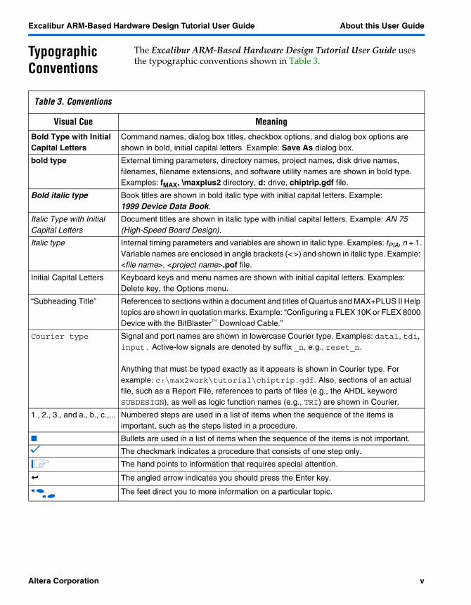
18. You should see the following messages reporting that the software mode was successful:
Figure 23. Software Mode Messages
19. Copy and paste the rom_image.txt file in the \rtl directory into the \simulation\modelsim directory.
20. A command line script, asm2rom.cmd, that performs the above tasks is also available in the \arm directory.
Create a ModelSim Project
If your previous ModelSim session is still open, select End Simulation (Design menu) and select YES to quit simulating the previous project. From the File menu, select New, then New Project. Continue with step 3 below.
1. Start ModelSim and choose Run ModelSim from options available.
2. Click on Create a Project in the next window.
3. In the New Project’s Home: window select ../arm_tutorial/tutorial_stripemodel
4. In the New Project’s Name: window, enter rtl.
5. Click OK.
6. Select No when prompted for a new HDL source file.
7. Click Done on the ModelSim welcome window.
ModelSim creates a work directory in the \tutorial_stripemodel\rtl directory. You must edit the rtl.mpf project file by adding the Veriuser variable to the project. This provides the ModelSim software with the path to the dynamically loaded objects for Verilog PLI applications. This enables the ModelSim software to interface with the Excalibur full stripe model.
50 Altera Corporation

Excalibur ARM-Based Hardware Design Tutorial User Guide Getting Started
1
Getting Started
8. Open the rtl.mpf file using any text editor.
9. Add the text:
Veriuser = $MG_LIB/mti_modelsim_verilog/libmgmm.so to
under the VSIM section after the Veriuser comments line. (you can cut and paste the text from the edit_mpf.txt file in the \rtl folder.
10. Save and close the rtl.mpf file.
Compile the Design Files
To compile the design files, perform the followng steps:
1. Select Compile (Design menu).
2. To add the include file directory, select Default Options.
3. Click Done.
4. Select the Verilog Tab and click the Add Include Dir button.
5. Browse to \arm_tutorial\tutorial_stripemodel.
6. Click Open.
7. Click OK.
8. In the Compile HDL Source window, browse to the \arm_tutorial\tutorial_stripemodel directory
9. Compile the following files: alu.v, regfile.v, wait_state_gen.v, ahb_slave_sm.v, pld_slave.v, arm_processor_ebi.v.
Compile the Testbench and Model Files
Follow these steps to compile the testbench files and the full stripe model files. The compile_fullmodel.do file compiles the model and the required wrapper files according to the paths given in the fullmodel.mft options file.
1. Browse to the \arm_tutorial\tutorial_stripemodel\rtl folder.
2. Compile arm_top_ebi.v, arm_top_tb.v and simple_rom.v.
Altera Corporation 51

Getting Started Excalibur ARM-Based Hardware Design Tutorial User Guide
3. Click Done.
4. Select Execute Macro (Macro menu).
5. Select compile_fullmodel.do.
� This .do file, shown below, compiles the stripe model and wrapper files needed to perform simulation with the full stripe model. The model file is epxa10.v; the wrapper files are alt_exc_stripe.v and model_wrappers.v. You can also compile these files separately, instead of using the compile_fullmodel.do file. The paths to these files are specified in the .do file.
6. Click OK.
compile_fullmodel.do
# Verilog Build requirements for RTL simulation of the Full Stripe Model# Device = epxa10
vlog "$env(QUARTUS_ROOTDIR)/eda/sim_lib/excalibur/lpm/alt_exc_stripe.v"
vlog "$env(QUARTUS_ROOTDIR)/eda/sim_lib/excalibur/lpm/model_wrappers.v"
vlog "$env(MG_MODEL_PATH)/epxa10/$env(MG_MODEL_REV)/mti_modelsim_verilog/epxa10.v"
Simulate
� For faster simulation times, use the ModelSim PE or SE software rather than the ModelSim-Altera simulation tool, for stripe-model simulation.
To simulate the model, perform the following steps:
1. Select Load New Design (Design menu).
2. Scroll down and find the arm_top_tb module, select it and click Load.
You might receive several benign timescale warnings, which do not affect the simulation.
3. Select Execute Macro (Macro menu).
4. Select wave.do and click OK.
52 Altera Corporation

Excalibur ARM-Based Hardware Design Tutorial User Guide Getting Started
1
Getting Started
Wave.do sets up the format of the ModelSim waveform window with particular signals in the design. It shows the main AHB signals, inputs, and outputs from the design.
5. Type run -all at the ModelSim prompt and select Enter to begin the simulation.
The testbench runs for 450 µs before stopping. Information messages are displayed in the ModelSim window indicating the status of the simulation.
When the simulation completes, you can view the results in the waveform window. The result_low and HRData bus signals show the results from the ALU operations. You can also view the internal stripe general purpose registers r0 through r10 as shown at the bottom of the wave window, shown in Figure 18.
Figure 24. Registers r0 through r10
Compilation
Refer to “Compilation” on page 30 and repeat steps 1 to 5 of “Compiler Settings”. Also repeat steps 1 to 3 of the EDA settings on page 31. Continue as shown below:
4. Click Settings next to Simulation Tool.
5. Check the option Output Excalibur Stripe as a single module.
6. Click OK in the Verilog HDL Output Settings box.
7. Click OK.
Altera Corporation 53

Getting Started Excalibur ARM-Based Hardware Design Tutorial User Guide
Compiling the Design
To compile the arm_top_ebi design, choose Start Compilation (Processing menu).
The compiler begins to compile the arm_top_ebi design entity, and any subordinate design entities, using the arm_top_ebi compiler settings. The results of the compilation are updated in the Compilation Report window. Compilation takes appoximately 10 minutes.
The compiler may generate one or more of the following warning messages that do not affect the outcome of your design, as shown in Figure 19 on page 49.
Figure 25. Compilation Warnings
Timing Simulation using the Full Stripe Model
� It is recommended that you use the full version of ModelSim rather than the Altera OEM version in this section. The full version will provide faster simulation time.
Create a ModelSim Project
If your previous ModelSim session is still open, select End Simulation (Design menu) and select YES to quit simulating the previous project. Close ModelSim by selecting Quit (File menu).
� You must quit the ModelSim software before each simulation session when using the full stripe model to avoid errors.
1. Start ModelSim and choose Run ModelSim from the selection of choices.
2. Click on Create a Project in the next window.
3. In the New Project’s Home: window select \altera\arm_tutorial\ tutorial_stripemodel\simulation.
54 Altera Corporation

Excalibur ARM-Based Hardware Design Tutorial User Guide Getting Started
1
Getting Started
4. In the New Project’s Name: window, type modelsim.
5. Click OK.
6. Select No when prompted for a new HDL source file.
7. Click Done on the ModelSim welcome window.
The ModelSim software creates a work directory in the tutorial_stripemodel\ simulation\modelsim directory.
You must edit the modelsim.mpf project file by adding the Veriuser variable to the project. This provides ModelSim with the path to the dynamically-loaded objects for Verilog PLI applications. This enables ModelSim to interface with the Excalibur full-stripe model.
8. Open the modelsim.mpf file using any text editor.
9. Add the text, Veriuser = $ MG_LIB\mti_modelsim_verilog/libmgmm.so under the VSIM section. (you can cut and paste the text from the edit_mpf.txt file in the \modelsim folder.
10. Save and close the modelsim.mpf file.
Compile the Design Files
Compile the design files, following the steps below:
1. Select Compile (Design menu).
2. Browse to the directory \arm_tutorial\tutorial_stripemodel\simulation\modelsim
3. In the Files of type box select All files(*.*).
4. Select arm_top_ebi.vo and click Compile.
Compile the Testbench and Model Files
Use the following steps to compile the testbench files, the full stripe model files, and the apex20ke_atoms file. The compile_fullmodel.do file compiles the model and the required wrapper files.
1. Browse to the folder \arm_tutorial\tutorial_stripemodel\simulation\modelsim.
Altera Corporation 55

Getting Started Excalibur ARM-Based Hardware Design Tutorial User Guide
2. Compile arm_top_tb.v and simple_rom.v
3. In the \<path to Quartus>\eda\sim_lib directory, select apex20ke_atoms.v and click Compile.
4. Click Done.
5. Select Execute Macro (Macro menu).
6. Select compile_fullmodel.do.
7. Click OK.
Simulate
Simulate the design, following the steps below:
1. Select Load New Design (Design menu).
2. Select the arm_top_tb module.
3. Click Load.
Viewing the Signals
You can view signals in the design by opening the waveform window and viewing the desired signals.
1. Select Wave (View menu).
2. Select Structure (View menu).
3. Select Signal (View menu)
4. Select the structure to which you wish to add signals.
5. In the signals window, select the desired signals.
6. Drag and drop the signals into the waveform window.
7. Type run -all at the ModelSim prompt to begin simulation.
The testbench runs for 600 µs before stopping. Comments indicating the simulation status are displayed in the ModelSim window. The results should match those seen in the RTL simulation section.
56 Altera Corporation

User Guide
2
Appendix AAppendix A
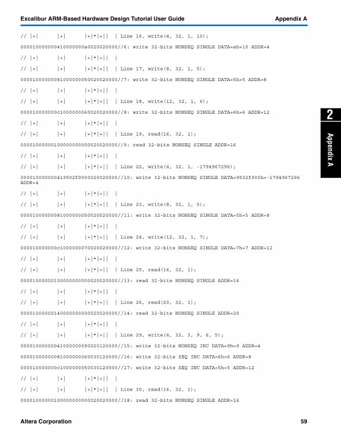
Contents of Mastercommands.dat
The contents of the mastercommands.dat are:
/////////////////////////////////////////////////////////////////////////////////////////////
//
// Altera upCore Bus Transaction Simulator Master Port Command File
//
// mastercommands.dat
//
// This file is interpretted by apex20ke_atoms.v to simulate the issueing of read/write
// instructions to the PLD by the microprocessor via the AHB3 master interface
//
// NB Only data, transaction and repeat fields are tested during the
// data beats of burst transactions
//
//
/////////////////////////////////////////////////////////////////////////////////////////////
// FORMAT
// / __________________________________| reserved (0000)
/// /
//| | ++++++++++++++++++++++++++++++++++ valid transaction 1=USE BUS 0=SILENT
//| |+ _______________________________
//| |+ / _________________________| address
//| |+/ /
//| |+| | +++++++++++++++++++++++++ write 1=WRITE 0=READ
//| |+| |+ _______________________
//| |+| |+ / _______________| write data / expected read data
//| |+| |+/ /
//| |+| |+| | ++++++++++++++++ reserved (0) (1=>lock)
//| |+| |+| |+
Altera Corporation 57

Appendix A Excalibur ARM-Based Hardware Design Tutorial User Guide
//| |+| |+| |+ /-------------- reserved (0) (1=>check read data)
//| |+| |+| |+/
//| |+| |+| |+| ************** transaction 0=IDLE, 1=BUSY, 2=NONSEQ, 3=SEQ
//| |+| |+| |+|*
//| |+| |+| |+|* /------------ reserved (0)
//| |+| |+| |+|*/
//| |+| |+| |+|*| ++++++++++++ burst 0=SINGLE, 1=INCR, 2=WRAP4, 3=INCR4, 4=WRAP8,
//| |+| |+| |+|*|+ 5=INCR8, 6=WRAP16, 7=INCR16
//| |+| |+| |+|*|+
//| |+| |+| |+|*|+ /---------- size 0=BYTE, 1=16 BIT, 2=32 BIT
//| |+| |+| |+|*|+/ ________
//| |+| |+| |+|*|+| / ______| repeat 0000..FFFF
//| |+| |+| |+|*|+|/ /
//| |+| |+| |+|*|+|| |
// / / / / / / / // /
// / / / / / / / // /
// |+| |+| |+|*|+|| | Line 2, idle(4);
00000000000000000000000000000004//0: idle CYCLES=4h=4
// |+| |+| |+|*|+|| |
// |+| |+| |+|*|+|| | Line 4, write(16, 32, 1, 15);
000010000001010000000f0020020000//1: write 32-bits NONSEQ SINGLE DATA=fh=15 ADDR=16
// |+| |+| |+|*|+|| |
// |+| |+| |+|*|+|| | Line 9, write(4, 32, 1, 10);
000010000000410000000a0020020000//2: write 32-bits NONSEQ SINGLE DATA=ah=10 ADDR=4
// |+| |+| |+|*|+|| |
// |+| |+| |+|*|+|| | Line 10, write(8, 32, 1, 5);
00001000000081000000050020020000//3: write 32-bits NONSEQ SINGLE DATA=5h=5 ADDR=8
// |+| |+| |+|*|+|| |
// |+| |+| |+|*|+|| | Line 11, write(12, 32, 1, 5);
000010000000c1000000050020020000//4: write 32-bits NONSEQ SINGLE DATA=5h=5 ADDR=12
// |+| |+| |+|*|+|| |
// |+| |+| |+|*|+|| | Line 13, read(16, 32, 1);
00001000000100000000000020020000//5: read 32-bits NONSEQ SINGLE ADDR=16
// |+| |+| |+|*|+|| |
58 Altera Corporation
Excalibur ARM-Based Hardware Design Tutorial User Guide GettingAppendix A
2
Appendix A
// |+| |+| |+|*|+|| | Line 16, write(4, 32, 1, 10);
000010000000410000000a0020020000//6: write 32-bits NONSEQ SINGLE DATA=ah=10 ADDR=4
// |+| |+| |+|*|+|| |
// |+| |+| |+|*|+|| | Line 17, write(8, 32, 1, 5);
00001000000081000000050020020000//7: write 32-bits NONSEQ SINGLE DATA=5h=5 ADDR=8
// |+| |+| |+|*|+|| |
// |+| |+| |+|*|+|| | Line 18, write(12, 32, 1, 6);
000010000000c1000000060020020000//8: write 32-bits NONSEQ SINGLE DATA=6h=6 ADDR=12
// |+| |+| |+|*|+|| |
// |+| |+| |+|*|+|| | Line 19, read(16, 32, 1);
00001000000100000000000020020000//9: read 32-bits NONSEQ SINGLE ADDR=16
// |+| |+| |+|*|+|| |
// |+| |+| |+|*|+|| | Line 22, write(4, 32, 1, -1794967296);
000010000000419502f9000020020000//10: write 32-bits NONSEQ SINGLE DATA=9502f900h=-1794967296 ADDR=4
// |+| |+| |+|*|+|| |
// |+| |+| |+|*|+|| | Line 23, write(8, 32, 1, 5);
00001000000081000000050020020000//11: write 32-bits NONSEQ SINGLE DATA=5h=5 ADDR=8
// |+| |+| |+|*|+|| |
// |+| |+| |+|*|+|| | Line 24, write(12, 32, 1, 7);
000010000000c1000000070020020000//12: write 32-bits NONSEQ SINGLE DATA=7h=7 ADDR=12
// |+| |+| |+|*|+|| |
// |+| |+| |+|*|+|| | Line 25, read(16, 32, 1);
00001000000100000000000020020000//13: read 32-bits NONSEQ SINGLE ADDR=16
// |+| |+| |+|*|+|| |
// |+| |+| |+|*|+|| | Line 26, read(20, 32, 1);
00001000000140000000000020020000//14: read 32-bits NONSEQ SINGLE ADDR=20
// |+| |+| |+|*|+|| |
// |+| |+| |+|*|+|| | Line 29, write(4, 32, 3, 9, 6, 5);
00001000000041000000090020120000//15: write 32-bits NONSEQ INC DATA=9h=9 ADDR=4
00001000000081000000060030120000//16: write 32-bits SEQ INC DATA=6h=6 ADDR=8
000010000000c1000000050030120000//17: write 32-bits SEQ INC DATA=5h=5 ADDR=12
// |+| |+| |+|*|+|| |
// |+| |+| |+|*|+|| | Line 30, read(16, 32, 1);
00001000000100000000000020020000//18: read 32-bits NONSEQ SINGLE ADDR=16
Altera Corporation 59

Appendix A Excalibur ARM-Based Hardware Design Tutorial User Guide
// |+| |+| |+|*|+|| |
// |+| |+| |+|*|+|| | Line 34, write(16, 32, 1, 10);
000010000001010000000a0020020000//19: write 32-bits NONSEQ SINGLE DATA=ah=10 ADDR=16
// |+| |+| |+|*|+|| |
// |+| |+| |+|*|+|| | Line 35, read(16, 32, 1);
00001000000100000000000020020000//20: read 32-bits NONSEQ SINGLE ADDR=16
// |+| |+| |+|*|+|| |
// |+| |+| |+|*|+|| | Line 36, read(16, 16, 1);
00001000000100000000000020010000//21: read 16-bits NONSEQ SINGLE ADDR=16
// |+| |+| |+|*|+|| |
// |+| |+| |+|*|+|| | Line 37, read(24, 32, 1);
00001000000180000000000020020000//22: read 32-bits NONSEQ SINGLE ADDR=24
// |+| |+| |+|*|+|| |
// |+| |+| |+|*|+|| |
60 Altera Corporation

User Guide
Appendix B
3
Appendix BContents of Input.dat
The contents of input.dat are:
idle(4); /*allow for the BFM to get passed is init issues*/
/*Dummy Transaction*/
write (16, 32, 1, 15);/* Need one transaction to get around the BFM driving out Undefined the first couple of cycles*/
/* Addition test*/
write (4, 32, 1, 10);/* write the 32-bit value 10 into address 4 */
write (8, 32, 1, 5);/* write the 32-bit value 5 into address 8 */
write (12, 32, 1, 5);/* write the 32-bit value 5 into address 12 to add the operands */
read (16, 32, 1); /* read the 32-bit value from address 16*/
/* Subtraction Test*/
write (4, 32, 1, 10);/* write the 32-bit value 10 into address 4 */
write (8, 32, 1, 5);/* write the 32-bit value 5 into address 8 */
write (12, 32, 1, 6);/* write the 32-bit value 6 into address 12 to subtract the operands */
read (16, 32, 1); /* read the 32-bit value from address 16*/
/*Multiplication Test*/
write (4, 32, 1, 2500000000);/* write the 32-bit value 2500000000 into address 4 */
write (8, 32, 1, 5);/* write the 32-bit value 5 into address 8 */
write (12, 32, 1, 7);/* write the 32-bit value 7 into address 12 to multiply the operands */
read (16, 32, 1); /* read the 32-bit value from address 16*/
read (20, 32, 1);/* read result High*/
/*INCR Burst test*/
Altera Corporation 61

Appendix B Excalibur ARM-Based Hardware Design Tutorial User Guide
write (4, 32, 3, 9 ,6, 5);/* burst test */
read (16, 32, 1); /* read the 32-bit value from address 16*/
/*Error Checking test*/
write (16, 32, 1, 10);/* Used to check the error condition of writing to a read only register */
read (16, 32, 1);/* read from the same read only address to see if check works*/
read (16, 16, 1); /* Used to test the error condition where the incorrect size data is used*/
read (24, 32, 1); /* Used to test error condition where transaction is not in address space*/
62 Altera Corporation

User Guide
Appendix C
4
Appendix CContents of Output.dat
The contents of output.dat are:
MASTER: trans=[ 2] addr=[00000010] WRITE data=[0000000f] expected=[0000000f] WORD ERROR
MASTER: trans=[ 3] addr=[00000004] WRITE data=[0000000a] expected=[0000000a] WORD OKAY
MASTER: trans=[ 4] addr=[00000008] WRITE data=[00000005] expected=[00000005] WORD OKAY
MASTER: trans=[ 5] addr=[0000000c] WRITE data=[00000005] expected=[00000005] WORD OKAY
MASTER: trans=[ 6] addr=[00000010] READ data=[0000000f] expected=[00000000] WORD OKAY
MASTER: trans=[ 7] addr=[00000004] WRITE data=[0000000a] expected=[0000000a] WORD OKAY
MASTER: trans=[ 8] addr=[00000008] WRITE data=[00000005] expected=[00000005] WORD OKAY
MASTER: trans=[ 9] addr=[0000000c] WRITE data=[00000006] expected=[00000006] WORD OKAY
MASTER: trans=[ 10] addr=[00000010] READ data=[00000005] expected=[00000000] WORD OKAY
MASTER: trans=[ 11] addr=[00000004] WRITE data=[9502f900] expected=[9502f900] WORD OKAY
MASTER: trans=[ 12] addr=[00000008] WRITE data=[00000005] expected=[00000005] WORD OKAY
MASTER: trans=[ 13] addr=[0000000c] WRITE data=[00000007] expected=[00000007] WORD OKAY
MASTER: trans=[ 14] addr=[00000010] READ data=[e90edd00] expected=[00000000] WORD OKAY
MASTER: trans=[ 15] addr=[00000014] READ data=[00000002] expected=[00000000] WORD OKAY
MASTER: trans=[ 16] addr=[00000004] WRITE data=[00000009] expected=[00000009] WORD OKAY
MASTER: trans=[ 17] addr=[00000008] WRITE data=[00000006] expected=[00000006] WORD OKAY
MASTER: trans=[ 18] addr=[0000000c] WRITE data=[00000005] expected=[00000005] WORD OKAY
MASTER: trans=[ 19] addr=[00000010] READ data=[0000000f] expected=[00000000] WORD OKAY
MASTER: trans=[ 20] addr=[00000010] WRITE data=[0000000a] expected=[0000000a] WORD ERROR
MASTER: trans=[ 21] addr=[00000010] READ data=[0000000f] expected=[00000000] WORD OKAY
MASTER: trans=[ 22] addr=[00000010] READ data=[0000000f] expected=[00000000] HALF WORD ERROR
MASTER: trans=[ 23] addr=[00000018] READ data=[0000000f] expected=[00000000] WORD ERROR
Altera Corporation 63

Notes:

User Guide
5
Appendix DAppendix D
Simulating VHDL ARM-BasedExcalibur Designs
If you are designing in VHDL, please use the following guidelines when simulating your design with the bus functional model and the full-stripe model.
Using the VHDL Bus Functional Model
Compile the appropriate simulation files first; these are listed below. Then compile your RTL files in hierarchical order, starting from the lowest-level file. For timing simulation, compile the VHDL netlist output file. You must also specify the standard delay format output file (.sdo) generated by the Quartus II software.
Behavioral Simulation
The following simulation files must be compiled in order when performing behavioral simulation with the bus functional model:
� altera_mf.vhd—megafunction file containing VHDL description of bus functional model
� altera_mf_components.vhd—megafunction component declaration file
� alt_exc_stripe.vhd—Excalibur simulation wrapper file� alt_exc_stripe_arch.bfm—Excalibur architecture declaration file
Timing Simulation
The following files must be compiled in order when performing timing simulation with the bus functional model:
� apex20ke_atoms.vhd—VHDL simulation models for APEX20KE atoms
� apex20ke_components.vhd - component declaration file
Using the VHDL Stripe Model
The SE version of ModelSim is required when using the VHDL Stripe Models.
For VHDL simulations, you do not need to add the "Veriuser" line to your ModelSim project.
Altera Corporation 65

Appendix D
Compile the appropriate simulation files first; these are listed below. Then compile your RTL files in hierarchical order starting from the lowest-level file. For timing simulation, compile the VHDL netlist output file. You must also specify the standard delay format output file (.sdo) generated by the Quartus II software.
Behavioral Simulation
The following simulation files must be compiled in order when performing behavioral simulation with the stripe model:
� epxa10.vhd—stripe model instantiation� model_wrappers.vhd—stripe model wrapper file� alt_exc_stripe.vhd—Excalibur simulation wrapper file� alt_exc_stripe_arch_fullmodel.vhd—Excalibur architecture
declaration file
Timing Simulation
The following files must be compiled in order when performing timing simulation with the stripe model:
� epxa10.vhd—stripe model instantiation� model_wrappers.vhd—stripe model wrapper file� apex20ke_atoms.vhd—VHDL simulation models for APEX20KE� apex20ke_components.vhd—component declaration file� apex20ke_stripe.vhd—wrapper file for stripe model� alt_exc_stripe.vhd—Excalibur simulation wrapper file� alt_exc_stripe_arch_fullmodel.vhd—Excalibur architecture file
66 Altera Corporation