Example 3.2 Flat slabs - · PDF fileExample 3.2 Flat slabs The following floor plan is...
18
Addis Ababa Institute of Technology School of Civil and Environmental Engineering Reinforced Concrete Structures II 1 Example 3.2 Flat slabs The following floor plan is intended to be a flat slab system. The slab thickness is 200mm thick and supports a characteristic dead load of 2.7 KN/m2 in addition to self-weight and a characteristic live load of 3 KN/m 2 . The slab is provided on edge beams of b w = 300 mm and h=400mm and all columns are 300mm by 300mm. Design the slab system using C20/25, S – 400. Solution: Step 1: Material property Concrete: = 0.85 ∗ 20 1.5 = 11.33 , 0.05 = 1.5 = 2.2 ɤ = 1.5
-
Upload
nguyenkhue -
Category
Documents
-
view
689 -
download
38
Transcript of Example 3.2 Flat slabs - · PDF fileExample 3.2 Flat slabs The following floor plan is...

Addis Ababa Institute of Technology School of Civil and Environmental Engineering Reinforced Concrete Structures II
1
Example 3.2 Flat slabs
The following floor plan is intended to be a flat slab system. The slab thickness is 200mm thick and
supports a characteristic dead load of 2.7 KN/m2 in addition to self-weight and a characteristic live load
of 3 KN/m2. The slab is provided on edge beams of bw= 300 mm and h=400mm and all columns are
300mm by 300mm. Design the slab system using C20/25, S – 400.
Solution:
Step 1: Material property
Concrete:
𝑓𝑐𝑑 = 0.85 ∗ 20
1.5= 11.33𝑀𝑝𝑎
𝑓𝑐𝑡𝑘, 0.05 = 1.5𝑀𝑝𝑎
𝑓𝑐𝑡𝑚 = 2.2𝑀𝑝𝑎
ɤ𝑐 = 1.5
Addis Ababa Institute of Technology School of Civil and Environmental Engineering Reinforced Concrete Structures II
2
𝑓𝑐𝑘 = 20𝑀𝑝𝑎, 𝑓𝑐𝑢 = 25𝑀𝑝𝑎
Rebar: 𝑓𝑦𝑘 = 400𝑀𝑝𝑎
𝑓𝑦𝑑 =𝑓𝑦𝑘
1.15= 347.83𝑀𝑝𝑎
ɛ𝑦𝑑 =𝑓𝑦𝑑
𝐸𝑠=
347.83
200= 1.74%0
Step 2: Depth check for deflection
According to ACI code minimum thickness of slabs without interior beams: without drop
panels for fyk = 400 Mpa
- Exterior panels with edge beams = ln /33
Slab considered to have edge beam if 0.8bf
s
I
I
for this case 8
8
20.33 101.05 0.8 !
19.33 10
bf
s
I xok
I x
(see the computation of Ib and Is on page 6)
- Interior panels = ln /33
Ln is the length of the clear span in longer direction.
- For edge panel Ln = 5500 - 300 = 5200mm
- For edge panel Ln = 6000 - 300 = 5700mm
5700172.73
33 33
nld mm
12cov 172.73 15 193.7
2 2h d er mm
<200 mm ok!
Step 3: Loading
Dead load:
Self-weight → 0.2 * 25 = 5 KN/m2
Imposed dead load → 2.7 KN/m2
Gk = 7.7 KN/m2
Variable Load:
Live load Qk = 3 KN/m2
Design load:
𝐺𝑑 = 1.35 ∗ 𝐺𝑘 = 1.35 ∗ 7.7 = 10.39 KN/m2
𝑄𝑑 = 1.5 ∗ 𝑄𝑘 = 1.5 ∗ 3 = 4.5 KN/m2
𝑇ℎ𝑒𝑟𝑒𝑓𝑜𝑟𝑒 𝑃𝑑 =14.89 KN/m2

Addis Ababa Institute of Technology School of Civil and Environmental Engineering Reinforced Concrete Structures II
3
Step 4: Limitations to direct design method
1. 3 span in each direction…………. Ok!
2. 5.5 6
1.15 2 1.25 2........ !4.8 4.8
y
x
Land Ok
L
3. Successive span length in each direction shall not differ by more than 1/3 of longer span.
16 5.5 0.5 6 2 !
3x Ok
4. All loads must be due to gravity only …… (By assuming there are no lateral loads on our
slab) Ok!
5. Factored live load must be less than twice of the factored dead load
4.52 0.43 2 !
10.395
LLOk
DL
6. Maximum offset of column from either axis between center-line of successive columns
shall not exceed 10% of the span in direction of offset …. Ok!
7. For a panel with beams between supports on all sides the relative stiffness of the beams
in the two perpendicular direction given by 2 2
1 2 2 1( . ) / ( . ) Shall not be less than 0.2 or greater than 5 …. Ok!
The direct design method (DDM) can be used.
Step 5: Analysis
Addis Ababa Institute of Technology School of Civil and Environmental Engineering Reinforced Concrete Structures II
4
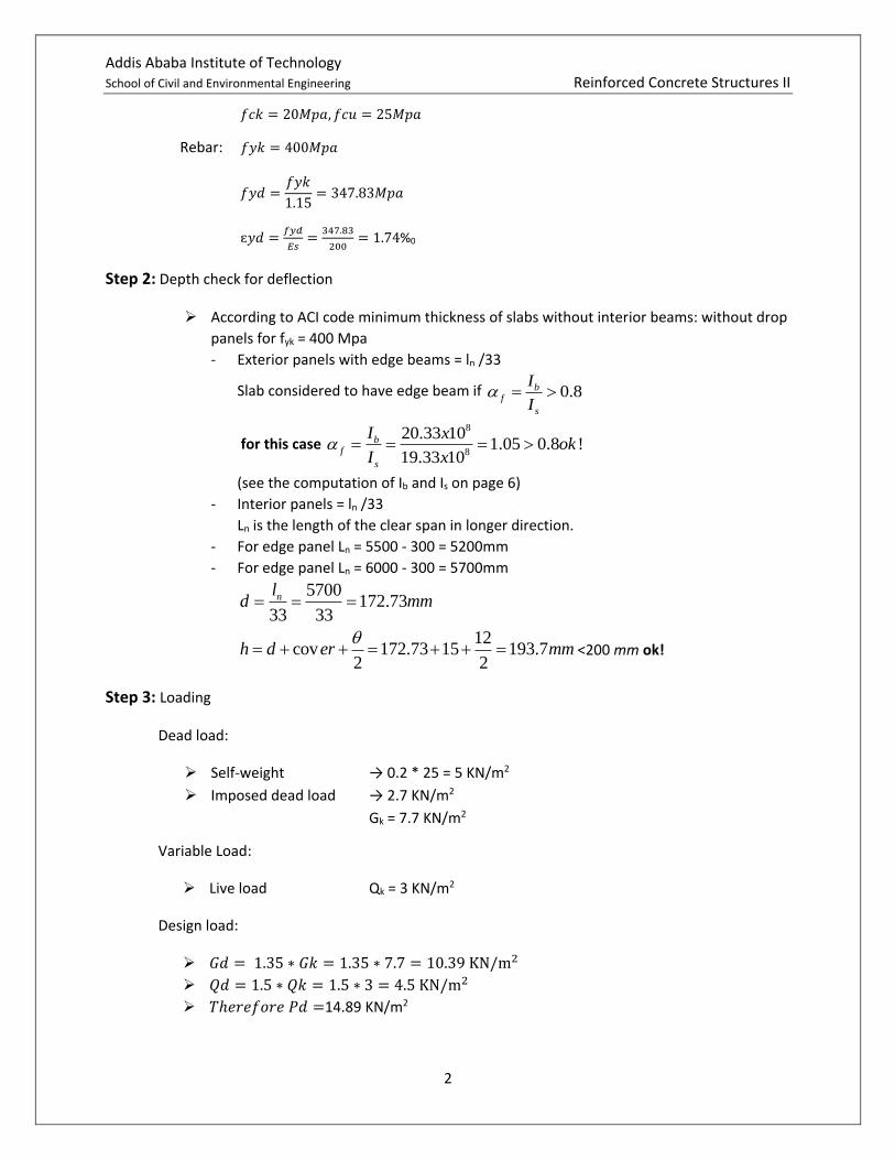
Due to symmetry strip-1 & strip-4 are similar and
Strip -2 & strip 3 are similar.
Strip -1 (along axis -1)
i. Compute l2, 2
4.8 0.32.4 0.15 2.55
2 2mm
ii. Compute Ln,𝑙𝑛 = {5500 − 300 = 5200𝑚𝑚
𝑏
𝑛 𝑎𝑥𝑒𝑠 𝐴 𝑎𝑛𝑑 𝐵 , 𝐶 𝑎𝑛𝑑 𝐷
6000 − 300 = 5700𝑚𝑚𝑏
𝑛 𝑎𝑥𝑒𝑠 𝐵 𝑎𝑛𝑑 𝐶
iii. Compute lx,𝑙𝑥 = 4.8𝑚 The minimum panel dimensions
𝑙𝑥 =4.8
4= 1.2
iv. Compute static moments
2
2
8
d no
P l lM
Between axis A & B or C & D 2
0
14.89 2.55 5.2128.34 .
8
x xM KN m
Between axis B & C 2
0
14.89 2.55 5.7154.2 .
8
x xM KN m
v. Longitudinal distribution of Mo
a. Between axis A & B or C & D
128.34 .oM KN m
N. B:-It is case-4, slabs without beam between interior supports and with edge beam.

Addis Ababa Institute of Technology School of Civil and Environmental Engineering Reinforced Concrete Structures II
5
- For panel between axis A and B
- For panel between axis C and D
b. Between axis B &C
153.38 .oM KN m
N.B Since there is a beam on the column strip some amount of the column strip moment will be
resisted by the beam
4
4
bcb
fb
cb
IE
lI
El
Since “l” is the same for both the beam and slab and cb csE E
bf
s
I
I

Addis Ababa Institute of Technology School of Civil and Environmental Engineering Reinforced Concrete Structures II
6
400
200
200
300
min( ,4 ) 200
h mm
hs mm
hw mm
bw mm
t hw hs mm
(500 200) 300 (300 200) 100225
(500 200) (300 200)
x x x xy mm
x x
3
3
9 6
1
12
12550 200
12
1.7 10 1700 10
sI bh
x x
x x mm
3 2 3 21 1300 200 (300 200)(225 100) 500 200 (500 200)(175 100)
12 12bI x x x x x x
6 6
6 4
1137.5 10 895.83 10
2033.33 10
x x
x mm
3 6 412550 200 1700 10
12sI x x x mm
6
6
2033.33 101.196
1700 10
b
s
I x
I x
Calculate 2
1
( )f
l
l
- 2 & &4 .8 For panel between axis A B or C Dm
- 1 6.0m for panel between axis B & C.

Addis Ababa Institute of Technology School of Civil and Environmental Engineering Reinforced Concrete Structures II
7
- For panel between axis A & B and C & D
2
1
4.8( ) 1.196( )
5.5f
1.045 1.0
- For panel between axis B & D
2
1
4.8( ) 1.196( )
6f
0.957 1.0
vi. Transverse distribution of moments (i.e. to column and middle strip)
For panel between axis A & B and C & D
a. Interior negative moment beam, M=89.84 KN.m
- There is intermediate beam
2
1
( ) 1.0f
2
1
4.80.87
5.5
- There is intermediate beam, 78.9 % (interpolated form table)
C.S moment 0.789 89.84 70.88 .x KN m
(1 0.789) 0.211
Half M.S moments 0.211 89.84 18.96 .x KN m
b. Positive moment, M=64.17 KN.m
2
1
( ) 1.0f
2
1
4.80.87
5.5
- 78.9% of moment to column strip
C.S moment 0.789 64.17 50.63 .x KN m
Half M.S moments 0.211 64.17 13.54 .x KN m
c. Exterior negative moment, M=38.50 KN.m
- 2
1
( ) 1.0f

Addis Ababa Institute of Technology School of Civil and Environmental Engineering Reinforced Concrete Structures II
8
- There is edge beam 0t
Calculate 2 s
c
I
3
[(1 0.63 )* ]3
.
x x yc
y
N B Always x y
Case 1:
3 3
1
3 4
0.2 0.2 *0.5 0.2 0.2 *0.3[(1 0.63* )*( )] [(1 0.63* )*( )]
0.5 3 0.3 3
(0.748*0.00133) (0.58 0.0008)
0.00097 0.00046
1.43*10
c
m
Case 2:
3 3
1
3 4
0.2 0.2 *0.3 0.2 0.3 *0.4[(1 0.63* )*( )] [(1 0.63* )*( )]
0.2 3 0.4 3
(0.37*0.00053) (0.5275 0.0036)
0.0002 0.00140
2.10*10
c
m
1 2
3 4
max ,
2.10*10
c c c
c m
- Calculate Is
Addis Ababa Institute of Technology School of Civil and Environmental Engineering Reinforced Concrete Structures II
9
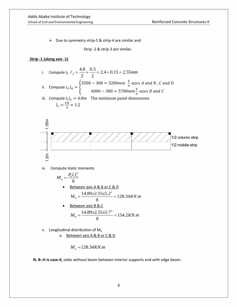
3
3
3 4
1* *
12
1*2.55*0.2
12
1.7*10
s
s
I b h
I
m
3
3
2.1*10
2* 2*1.7*10
0.618
t
s
C
I
Percentage of column strip moment can be determined by interpolation.
1
1
220.618, 1, 0.5 97.5281 1
220.618, 1, 1 93.821 1
20.872 94.76
1
t f
t f
llfor andl l
llfor andl l
lfor and thevalues obtained above
l
. 0.948*38.5
36.5
. 0.052*38.5
2.00
C S moment
KNm
M S moment
KNm
For panel between axis B & C
a) Interior negative moment, M = 100.23 KN.m
1
1
1
22 0, 0.8 751 1
22 1, 0.8 811 1
2 0.957, 80.7421
f
f
f
llinerpoliate for andl l
llinerpoliate for andl l
linerpoliate for and thevalues obtained abovel
. 0.8074*100.23
80.93
. 0.1926*100.23
19.3
C S moment
KNm
M S moment
KNm
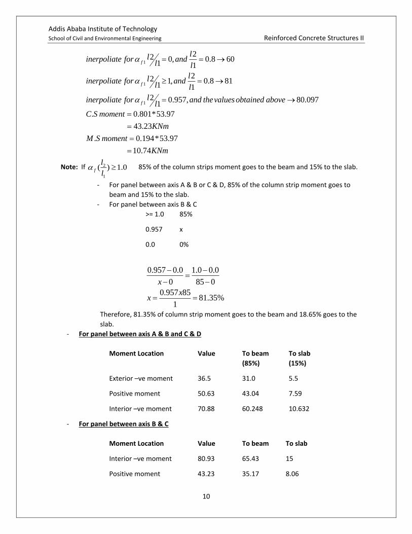
b) Positive moment, M = 53.97 KN.m
Addis Ababa Institute of Technology School of Civil and Environmental Engineering Reinforced Concrete Structures II
10
1
1
1
22 0, 0.8 601 1
22 1, 0.8 811 1
2 0.957, 80.0971
f
f
f
llinerpoliate for andl l
llinerpoliate for andl l
linerpoliate for and thevalues obtained abovel
. 0.801*53.97
43.23
. 0.194*53.97
10.74
C S moment
KNm
M S moment
KNm
Note: If 2
1
( ) 1.0f
l
l 85% of the column strips moment goes to the beam and 15% to the slab.
- For panel between axis A & B or C & D, 85% of the column strip moment goes to
beam and 15% to the slab.
- For panel between axis B & C
>= 1.0 85%
0.957 x
0.0 0%
0.957 0.0 1.0 0.0
0 85 0x
0.957 8581.35%
1
xx
Therefore, 81.35% of column strip moment goes to the beam and 18.65% goes to the
slab.
- For panel between axis A & B and C & D
Moment Location Value To beam
(85%)
To slab
(15%)
Exterior –ve moment 36.5 31.0 5.5
Positive moment 50.63 43.04 7.59
Interior –ve moment 70.88 60.248 10.632
- For panel between axis B & C
Moment Location Value To beam To slab
Interior –ve moment 80.93 65.43 15
Positive moment 43.23 35.17 8.06

Addis Ababa Institute of Technology School of Civil and Environmental Engineering Reinforced Concrete Structures II
11
Moment summary
Strip 2: [along axis 2]
i) Compute l2,
4.8 4.822 2
4.8
l
ii) Compute ln,
ln 5500 300 5200 / & &
6000 300 5700 / &
mmb naxis A B and C D
mmb naxis B C
iii) Compute lx, min 2, n 4.8lx l l m
Addis Ababa Institute of Technology School of Civil and Environmental Engineering Reinforced Concrete Structures II
12
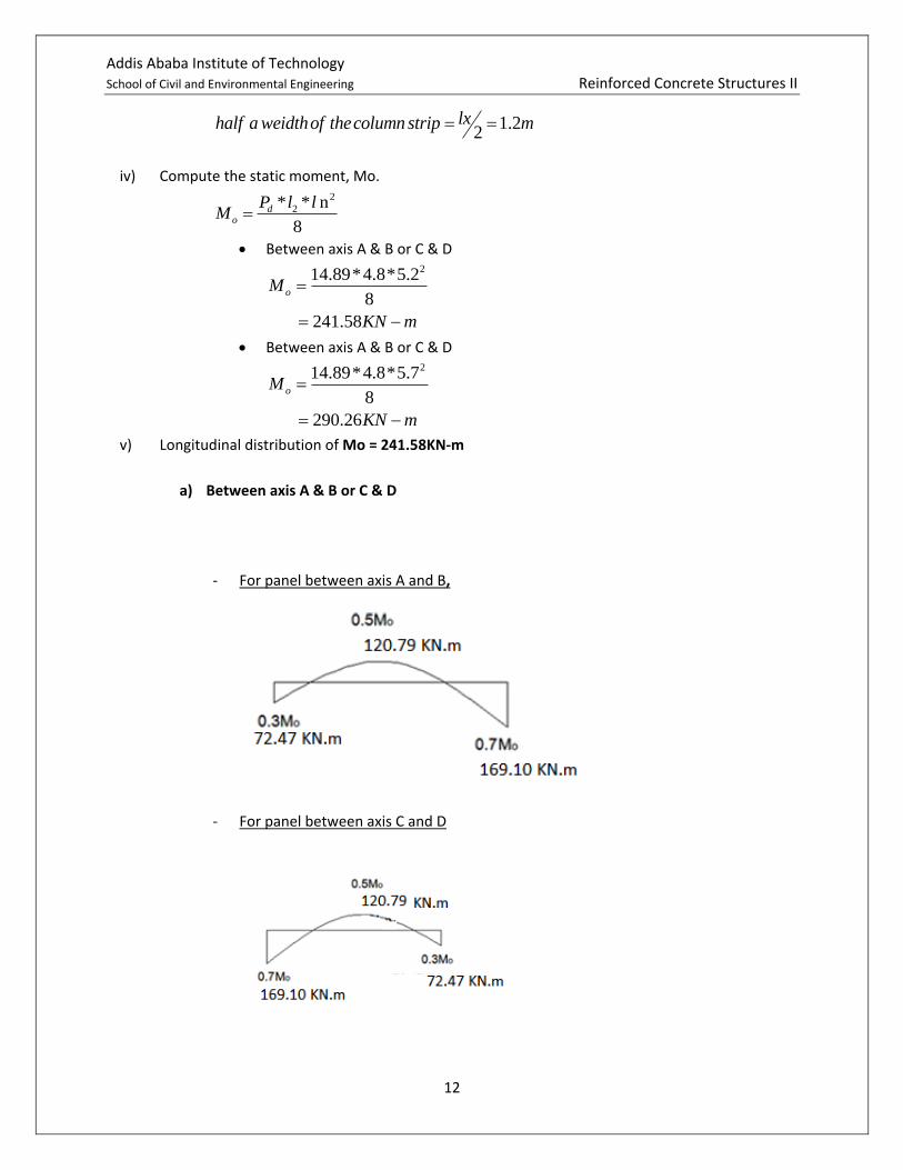
1.22
lxhalf a weidthof thecolumn strip m
iv) Compute the static moment, Mo. 2
2* * n
8
do
P l lM
Between axis A & B or C & D 214.89*4.8*5.2
8
241.58
oM
KN m
Between axis A & B or C & D 214.89*4.8*5.7
8
290.26
oM
KN m
v) Longitudinal distribution of Mo = 241.58KN-m
a) Between axis A & B or C & D
- For panel between axis A and B,
- For panel between axis C and D

Addis Ababa Institute of Technology School of Civil and Environmental Engineering Reinforced Concrete Structures II
13
b. Between axis B &C M0 =290.26KN-m
vi) Transverse distribution of moments (i.e to column and middle strip)
For panel between axis A & B and C & D
a) Interior negative moment, M=169.1 KN-m
No intermediate beam → α=0
75% of moment to column strip
. 0.75*169.1
126.8
. 0.125*169.1
21.14
C S moment
KNm
half M S moment
KNm
b) Positive moment, M=120.79 KN-m
No intermediate beam → α=0
60% of moment to column strip
. 0.6*120.79
72.47
. 0.2*120.79
24.16
C S moment
KNm
half M S moment
KNm
c) Exterior negative moment, M=72.47 KN-m
No intermediate beam → α=0
There is edge beam → βt≠0
calculate2*
t
s
C
I
3 42.10*10 ( )c m form previouscalculattake ion

Addis Ababa Institute of Technology School of Civil and Environmental Engineering Reinforced Concrete Structures II
14
3
3
3 4
1* *
12
1*4.8*0.2
12
3.2*10
s
s
I b h
I
m
3
3
2.1*10
2* 2*3.2*10
0.328
t
s
C
I
Percentage of column strip moment can be determined by interpolation
0 100%
0.328
2.5 75%
96.72%
t
t
x
x
. 0.9672*72.47
70.09
. 0.0164*72.47
1.188
C S moment
KNm
half M S moment
KNm
For panel between axis B & C
a) Interior negative moment, M = 188.67KN-m
No intermediate beam → α=0
75% of moment to column strip
. 0.75*188.67
141.5
. 0.125*188.67
23.58
C S moment
KNm
half M S moment
KNm
b) positive moment, M = 101.6KN-m
No intermediate beam → α=0
60% of moment to column strip

Addis Ababa Institute of Technology School of Civil and Environmental Engineering Reinforced Concrete Structures II
15
. 0.6*101.6
60.9
. 0.2*101.6
20.32
C S moment
KNm
half M S moment
KNm
Moment summary
Step 6: Design
cov2
10200 152
180
d h er for thebottomlayer bar
mm
Area of minimum reinforcement
,min
2
,min
0.26max ,0.0013
0.26*2.2*1000*180max ,0.0013*1000*180
400
max 257.4,234
257.4
ctm ts
yk
s
f b dA bd
f
A mm

Addis Ababa Institute of Technology School of Civil and Environmental Engineering Reinforced Concrete Structures II
16
Minimum spacing:
min max , 5 ,20S aggrigate size mm mm
Maximum spacing:
max
max
min 3 ,400 , f
0
in
40
S h mm for primary re orcement
S mm
Moment diagram (not drawn to scale)

Addis Ababa Institute of Technology School of Civil and Environmental Engineering Reinforced Concrete Structures II
17
strip Moment strip width
moment per meter ω As,req s, req s provided
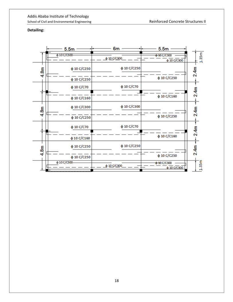
C.S 5.5 1.35 4.07 0.011 257.4 333 use ф 10 C/C300
7.59 1.35 5.62 0.015 257.4 333 use ф 10 C/C300
10.632 1.35 7.88 0.0216 257.4 333 use ф 10 C/C300
15.1 1.35 20.39 0.057 332.32 250 use ф 10 C/C300
8.06 1.35 10.88 0.03 257.4 333 use ф 10 C/C300
M.S 18.96 1.2 15.80 0.044 257.4 333 use ф 10 C/C300
13.54 1.2 11.28 0.317 257.4 333 use ф 10 C/C300
2 1.2 1.67 0.0045 257.4 333 use ф 10 C/C300
19.3 1.2 16.08 0.0446 261.9 333 use ф 10 C/C300
10.74 1.2 8.95 0.024 257.4 333 use ф 10 C/C300
C.S 126.8 2.4 52.63 0.157 921.99 90.9 use ф 10 C/C90
72.47 2.4 30.03 0.0889 521.19 166.67 use ф 10 C/C160
70.09 2.4 29.20 0.083 45.5 166.67 use ф 10 C/C160
141.5 2.4 58.96 0.177 1036.99 76.9 use ф 10 C/C70
60.9 2.4 25.40 0.072 422.8 200 use ф 10 C/C200
M.S 21.14 1.2 17.54 0.0487 286.01 333 use ф 10 C/C300
24.16 1.2 20.03 0.0559 327.9 250 use ф 10 C/C250
1.188 1.2 0.99 0.0027 257.4 333 use ф 10 C/C300
23.58 1.2 19.65 0.0559 327.9 250 use ф 10 C/C250
20.32 1.2 16.93 0.047 277.39 333 use ф 10 C/C300
Addis Ababa Institute of Technology School of Civil and Environmental Engineering Reinforced Concrete Structures II
18
Detailing: