EXAMPLE 1 - etu.edu.trmguler.etu.edu.tr/MAK205_Chapter1.pdf · EXAMPLE 1.1 Determine the ... This...
19
Fig. 1–4b Fig. 1–4c EXAMPLE 1.1 Determine the resultant internal loadings acting on the cross section at C of the beam shown in Fig. 1–4a. 180 N/m 540 N 2 m 4 m V C M C N C (b) B C (a) A B C 3 m 6 m 270 N/m Fig. 1–4 Solution Support Reactions. This problem can be solved in the most direct manner by considering segment CB of the beam, since then the support reactions at A do not have to be computed. Free-Body Diagram. Passing an imaginary section perpendicular to the longitudinal axis of the beam yields the free-body diagram of segment CB shown in Fig. 1–4b. It is important to keep the distributed loading exactly where it is on the segment until after the section is made. Only then should this loading be replaced by a single resultant force. Notice that the intensity of the distributed loading at C is found by proportion, i.e., from Fig.1–4a, The magnitude of the resultant of the distributed load is equal to the area under the loading curve (triangle) and acts throughthe centroid of this area.Thus, which acts from C as shown in Fig. 1–4b. Equations of Equilibrium. Applying the equations of equilibrium we have Ans. Ans. Ans. The negative sign indicates that acts in the opposite direction to that shown on the free-body diagram. Try solving this problem using segment AC, by first obtaining the support reactions at A, which are given in Fig. 1–4c. M C M C =- 1080 N # m - M C - 540 N12 m2 = 0 d +© M C = 0; V C = 540 N V C - 540 N = 0 + q© F y = 0; N C = 0 - N C = 0 : + © F x = 0; 1> 316 m2 = 2 m F = 1 2 1180 N> m216 m2 = 540 N, w = 180 N> m. w> 6 m = 1270 N> m2> 9m, 1.5 m 0.5 m 1 m 180 N/m 90 N/m 540 N 135 N V C M C N C (c) 1215 N 3645 Nm C A
Transcript of EXAMPLE 1 - etu.edu.trmguler.etu.edu.tr/MAK205_Chapter1.pdf · EXAMPLE 1.1 Determine the ... This...

Fig. 1–4b
Fig. 1–4c
E X A M P L E 1.1
Determine the resultant internal loadings acting on the cross sectionat C of the beam shown in Fig. 1–4a.
180 N/m
540 N
2 m 4 mVC
MC
NC
(b)
BC
(a)
A B
C3 m 6 m
270 N/m
Fig. 1–4Solution
Support Reactions. This problem can be solved in the most directmanner by considering segment CB of the beam, since then thesupport reactions at A do not have to be computed.
Free-Body Diagram. Passing an imaginary section perpendicular to thelongitudinal axis of the beam yields the free-body diagram of segmentCB shown in Fig. 1–4b. It is important to keep the distributed loadingexactly where it is on the segment until after the section is made. Onlythen should this loading be replaced by a single resultant force. Noticethat the intensity of the distributed loading at C is found by proportion,i.e., from Fig.1–4a, Themagnitude of the resultant of the distributed load is equal to the areaunder the loading curve (triangle) and acts throughthe centroid of thisarea.Thus, which acts from C as shown in Fig. 1–4b.
Equations of Equilibrium. Applying the equations of equilibriumwe have
Ans.
Ans.
Ans.
The negative sign indicates that acts in the opposite direction tothat shown on the free-body diagram. Try solving this problem usingsegment AC, by first obtaining the support reactions at A, which aregiven in Fig. 1–4c.
MC
MC = -1080 N # m-MC - 540 N12 m2 = 0d+© MC = 0;
VC = 540 N
VC - 540 N = 0+q © Fy = 0;
NC = 0
-NC = 0:+ © Fx = 0;
1>316 m2 = 2 mF = 121180 N>m216 m2 = 540 N,
w = 180 N>m.w>6 m = 1270 N>m2>9m,
1.5 m0.5 m
1 m
180 N/m90 N/m
540 N135 N
VC
MC
NC
(c)
1215 N
3645 NmCA

Fig. 1–5c
Fig. 1–5b
E X A M P L E 1.2
Determine the resultant internal loadings acting on the cross sectionat C of the machine shaft shown in Fig. 1–5a. The shaft is supportedby bearings at A and B, which exert only vertical forces on the shaft.
225 N
CD
200 mm100 mm 100 mm
50 mm50 mm
800 N/m
B
(a)
A
Fig. 1–5
0.275 m0.125 m
(800 N/m)(0.150 m) = 120 N
0.100 m
225 N
Ay By(b)
B
SolutionWe will solve this problem using segment AC of the shaft.
Support Reactions. A free-body diagram of the entire shaft is shownin Fig. 1–5b. Since segment AC is to be considered, only the reactionat A has to be determined. Why?
The negative sign for indicates that acts in the opposite sense tothat shown on the free-body diagram.
Free-Body Diagram. Passing an imaginary section perpendicular tothe axis of the shaft through C yields the free-body diagram of segmentAC shown in Fig. 1–5c.
Equations of Equilibrium.
Ans.
Ans.
Ans.
What do the negative signs for and indicate? As an exercise,calculate the reaction at B and try to obtain the same results usingsegment CBD of the shaft.
MCVC
MC = -5.69 N # mMC + 40 N10.025 m2 + 18.75 N10.250 m2 = 0d+© MC = 0;
VC = -58.8 N
-18.75 N - 40 N - VC = 0+q © Fy = 0;
NC = 0:+ © Fx = 0;
AyAy
Ay = -18.75 N
-Ay10.400 m2 + 120 N10.125 m2 - 225 N10.100 m2 = 0d+ © MB = 0;
(c)
40 N18.75 N
0.250 m
0.025 m
MC
VC
CA
NC

Fig. 1–6a
E X A M P L E 1.3
The hoist in Fig. 1–6a consists of the beam AB and attached pulleys,the cable, and the motor. Determine the resultant internal loadingsacting on the cross section at C if the motor is lifting the 2000 N ( 200 kg) load W with constant velocity. Neglect the weight of thepulleys and beam.
(b)
1.125 m
C
125 m
2000 N
2000 N
VC
NCMC
A
Fig. 1–6
1 m 0.5 m1.5 m
125 mm
125 mm
A CD
B
W (a)
SolutionThe most direct way to solve this problem is to section both the cableand the beam at C and then consider the entire left segment.Free-Body Diagram. See Fig. 1–6b.
Equations of Equilibrium.
Ans.Ans.
Ans.As an exercise, try obtaining these same results by considering just
the beam segment AC, i.e., remove the pulley at A from the beam andshow the 2000-N force components of the pulley acting on the beamsegment AC. Also, this problem can be worked by first finding thereactions at B, (Bx 0, By 4000 N, MB 7000 N m) and thenconsidering segment CB.
MC = -2000 lb # ft500 lb 14.5 ft2 - 500 lb 10.5 ft2 + MC = 0d+ © MC = 0;-500 lb - VC = 0 VC = -500 lb+q © Fy = 0;500 lb + NC = 0 NC = -500 lb:+ © Fx = 0; 2000 N
2000 N
2000 N
2000 N
2000 N • m2000 N(1.125 m) 2000 N(0.125 m) 1 MC 0

Fig. 1–7d
Fig. 1–7c
Fig. 1–7b
6200 N
= 4650 N= 7750 NFBA FBD
34
5
(c)
B
(d)
MG
NG
VG
1 m
34
5
7750 N1500 N
A G
E X A M P L E 1.4
Determine the resultant internal loadings acting on the cross sectionat G of the wooden beam shown in Fig. 1–7a. Assume the joints at A,B, C, D, and E are pin connected.
(a)
600 N/m
1 m 1 m 3 m
1500 N
A
B
G D
C
1.5 m
E
Fig. 1–7
1.5 m
3 m (3 m) = 2 m
(3 m)(600 N/m) = 900 N12
1500 N
= 2400 N
= 6200 N
= 6200 N
Ey
Ex
FBC
(b)
23
Solution
Support Reactions. Here we will consider segment AG for theanalysis. A free-body diagram of the entire structure is shown in Fig. 1–7b. Verify the computed reactions at E and C. In particular,note that BC is a two-force member since only two forces act on it.For this reason, the reaction at C must be horizontal as shown.
Since BA and BD are also two-force members, the free-bodydiagram of joint B is shown in Fig. 1–7c. Again, verify the magnitudesof the computed forces and
Free-Body Diagram. Using the result for the left section AGof the beam is shown in Fig. 1–7d.
Equations of Equilibrium. Applying the equations of equilibriumto segment AG, we have
Ans.
Ans.
Ans.
As an exercise, compute these same results using segment GE.
MG = 6300 lb # ftMG - 17750 lb2A35 B 12 ft2 + 1500 lb 12 ft2 = 0d+ © MG = 0;
VG = 3150 lb
-1500 lb + 7750 lb A35 B - VG = 0+q © Fy = 0;
7750 lb A45 B + NG = 0 NG = -6200 lb:+ © Fx = 0;
FBA,
FBD.FBA
7750 N
1500 N 7750 N 3150 N
(7750 N)
6200 N
(1 m) (1500 N)(1 m) 0
3150 N • m

Fig. 1–8a
E X A M P L E 1.5
Determine the resultant internal loadings acting on the cross sectionat B of the pipe shown in Fig. 1–8a. The pipe has a mass of 2 kg/mand is subjected to both a vertical force of 50 N and a couple momentof at its end A. It is fixed to the wall at C.
SolutionThe problem can be solved by considering segment AB, which doesnot involve the support reactions at C.
Free-Body Diagram. The x, y, z axes are established at B and thefree-body diagram of segment AB is shown in Fig. 1–8b. The resultantforce and moment components at the section are assumed to act inthe positive coordinate directions and to pass through the centroid ofthe cross-sectional area at B. The weight of each segment of pipe iscalculated as follows:
These forces act through the center of gravity of each segment.
Equations of Equilibrium. Applying the six scalar equations ofequilibrium, we have*
Ans.Ans.
Ans.
Ans.
Ans.
Ans.
What do the negative signs for and indicate? Note that the normal force whereas the shear
force is Also, the torsional moment is and the bending moment is
*The magnitude of each moment about an axis is equal to the magnitude of each forcetimes the perpendicular distance from the axis to the line of action of the force. Thedirection of each moment is determined using the right-hand rule, with positivemoments (thumb) directed along the positive coordinate axes.
30.3 N # m.MB = 2130.322 + 102 =1MB2y = 77.8 N # mTB =21022 + 184.322 = 84.3 N.VB =
NB = 1FB2y = 0,1MB2y1MB2x
1MB2z = 0©1MB2z = 0;
1MB2y = -77.8 N # m1MB2y + 24.525 N 10.625 m2 + 50 N 11.25 m2 = 0©1MB2y = 0;
1MB2x = -30.3 N # m- 9.81 N 10.25 m2 = 0
1MB2x + 70 N # m - 50 N 10.5 m2 - 24.525 N 10.5 m2©1MB2x = 0;
1FB2z = 84.3 N
1FB2z - 9.81 N - 24.525 N - 50 N = 0© Fz = 0;
1FB2y = 0© Fy = 0;
1FB2x = 0© Fx = 0;
WAD = 12 kg>m211.25 m219.81 N>kg2 = 24.525 N
WBD = 12 kg>m210.5 m219.81 N>kg2 = 9.81 N
70 N # m
0.625 m
70 N·m
(b)
y0.625 m
A
50 N
0.25 m0.25 m
x
z
9.81 N
24.525 NB
(MB)z
(MB)y
(MB)x
(FB)x
(FB)y
(FB)z
Fig. 1–8
0.75 m
50 N
1.25 m
B
A
0.5 m
C
D
70 Nm(a)

Fig. 1–16a
(d)
30 kN
85.7 MPa35 mm
10 mm
Fig. 1–16
E X A M P L E 1.6
The bar in Fig. 1–16a has a constant width of 35 mm and a thicknessof 10 mm. Determine the maximum average normal stress in the barwhen it is subjected to the loading shown.
(b)
9 kN
9 kN
12 kN
12 kN
= 12 kNPAB
= 30 kNPBC
22 kN= 22 kNPCD
P(kN)
x122230
(c)
12 kN 22 kN9 kN
9 kN
4 kN
4 kN35 mm
A DB C
(a)
Solution
Internal Loading. By inspection, the internal axial forces in regions AB,BC, and CD are all constant yet have different magnitudes. Using themethod of sections, these loadings are determined in Fig. 1–16b; and thenormal force diagram which represents these results graphically is shownin Fig. 1–16c. By inspection, the largest loading is in region BC, where
Since the cross-sectional area of the bar is constant, thelargest average normal stress also occurs within this region of the bar.
Average Normal Stress. Applying Eq. 1–6, we have
Ans.
The stress distribution acting on an arbitrary cross section of thebar within region BC is shown in Fig. 1–16d. Graphically the volume(or “block”) represented by this distribution of stress is equivalent tothe load of 30 kN; that is, 30 kN = 185.7 MPa2135 mm2110 mm2.
sBC =PBCA
=3011032N
10.035 m210.010 m2 = 85.7 MPa
PBC = 30 kN.
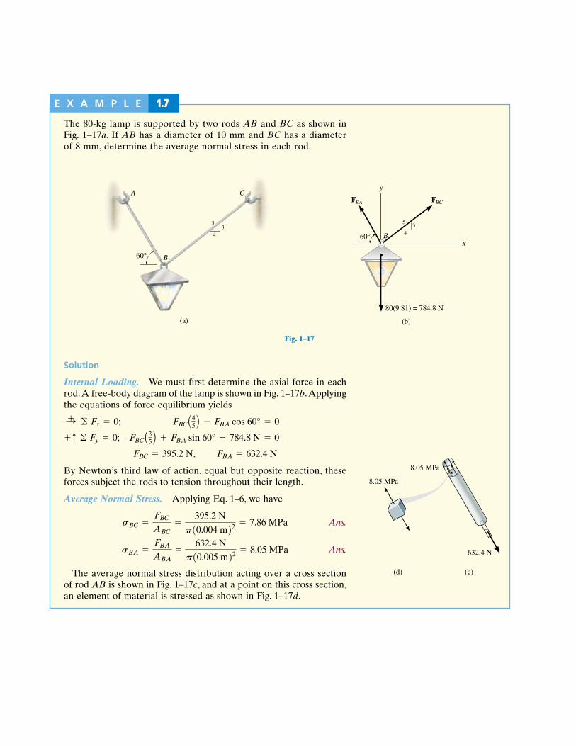
Fig. 1–17c
Fig. 1–17b
E X A M P L E 1.7
The 80-kg lamp is supported by two rods AB and BC as shown inFig. 1–17a. If AB has a diameter of 10 mm and BC has a diameterof 8 mm, determine the average normal stress in each rod.
(b)
60°
FBA FBC
y
x
80(9.81) = 784.8 N
B
34
5
A
60° B
C
34
5
(a)
Fig. 1–17
Solution
Internal Loading. We must first determine the axial force in eachrod.A free-body diagram of the lamp is shown in Fig. 1–17b.Applyingthe equations of force equilibrium yields
By Newton’s third law of action, equal but opposite reaction, theseforces subject the rods to tension throughout their length.
Average Normal Stress. Applying Eq. 1–6, we have
Ans.
Ans.
The average normal stress distribution acting over a cross sectionof rod AB is shown in Fig. 1–17c, and at a point on this cross section,an element of material is stressed as shown in Fig. 1–17d.
sBA =FBAABA
=632.4 N
p10.005 m22 = 8.05 MPa
sBC =FBCABC
=395.2 N
p10.004 m22 = 7.86 MPa
FBC = 395.2 N, FBA = 632.4 N
FBC A35 B + FBA sin 60° - 784.8 N = 0+q © Fy = 0;
FBC A45 B - FBA cos 60° = 0:+ © Fx = 0;
632.4 N
8.05 MPa
8.05 MPa
(c)(d)
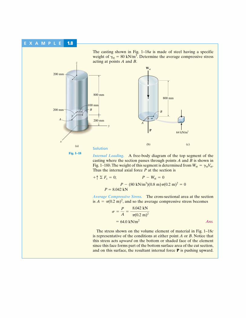
Fig. 1–18b
E X A M P L E 1.8
The casting shown in Fig. 1–18a is made of steel having a specificweight of st 80 kN/m3. Determine the average compressive stressacting at points A and B.
200 mm
200 mm
800 mm
y
z
x
(a)
A
B200 mm
100 mm
Fig. 1–18
800 mm
(b)
A
P
(c)
64 kN/m
B
Wst
2
Solution
Internal Loading. A free-body diagram of the top segment of thecasting where the section passes through points A and B is shown inFig. 1–18b.The weight of this segment is determined from Thus the internal axial force P at the section is
P (80 kN/m3)(0.8 m)(0.2 m)2 0P 8.042 kN
Average Compressive Stress. The cross-sectional area at the sectionis A (0.2 m)2, and so the average compressive stress becomes
Ans.
The stress shown on the volume element of material in Fig. 1–18cis representative of the conditions at either point A or B. Notice thatthis stress acts upward on the bottom or shaded face of the elementsince this face forms part of the bottom surface area of the cut section,and on this surface, the resultant internal force P is pushing upward.
= 9.36 psi
s =P
A=
2381 lb
p10.75 ft22
P - Wst = 0+q © Fz = 0;
Wst = gstVst.
8.042 kN
64.0 kN/m2
(0.2 m)2
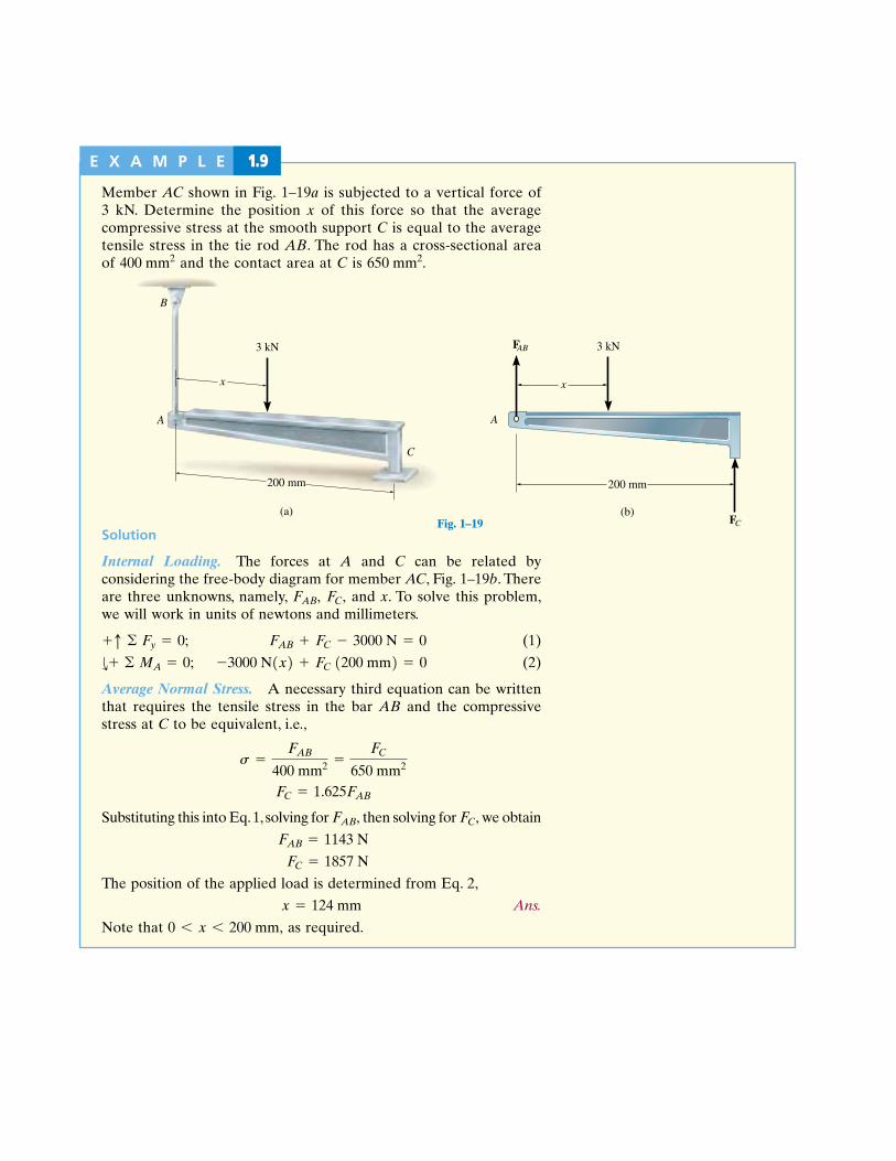
Fig. 1–19b
E X A M P L E 1.9
Member AC shown in Fig. 1–19a is subjected to a vertical force of3 kN. Determine the position x of this force so that the averagecompressive stress at the smooth support C is equal to the averagetensile stress in the tie rod AB. The rod has a cross-sectional areaof and the contact area at C is 650 mm2.400 mm2
x
A
B
C
200 mm
(a)
3 kN
Fig. 1–19(b)
x
3 kN
A
200 mm
FAB
FC
Solution
Internal Loading. The forces at A and C can be related byconsidering the free-body diagram for member AC, Fig. 1–19b. Thereare three unknowns, namely, and x. To solve this problem,we will work in units of newtons and millimeters.
(1)
(2)
Average Normal Stress. A necessary third equation can be writtenthat requires the tensile stress in the bar AB and the compressivestress at C to be equivalent, i.e.,
Substituting this into Eq.1, solving for then solving for we obtain
The position of the applied load is determined from Eq. 2,
Ans.
Note that as required.0 6 x 6 200 mm,
x = 124 mm
FC = 1857 N
FAB = 1143 N
FC,FAB,
FC = 1.625FAB
s =FAB
400 mm2 =FC
650 mm2
-3000 N1x2 + FC 1200 mm2 = 0d+ © MA = 0;
FAB + FC - 3000 N = 0+q © Fy = 0;
FC,FAB,

Fig. 1–24a
E X A M P L E 1.10
The bar shown in Fig. 1–24a has a square cross section for which thedepth and thickness are 40 mm. If an axial force of 800 N is appliedalong the centroidal axis of the bar’s cross-sectional area, determinethe average normal stress and average shear stress acting on thematerial along (a) section plane a–a and (b) section plane b–b.
a
a
b
b
800 N
20 mm60°
(a)
20 mm
(b)
800 N P = 800 N
(c)
500 kPa
500 kPa
Fig. 1–24
Solution
Part (a)Internal Loading. The bar is sectioned, Fig. 1–24b, and the internalresultant loading consists only of an axial force for which
Average Stress. The average normal stress is determined from Eq.1–6.
Ans.
No shear stress exists on the section, since the shear force at thesection is zero.
Ans.
The distribution of average normal stress over the cross section isshown in Fig. 1–24c.
tavg = 0
s =P
A=
800 N10.04 m210.04 m2 = 500 kPa
P = 800 N.

Fig. 1–24e
Fig. 1–24d
V
800 N
60°
(d)
30°
y y
x
x30°
60°N
800 N
Part (b)Internal Loading. If the bar is sectioned along b–b, the free-bodydiagram of the left segment is shown in Fig. 1–24d. Here both a normalforce (N) and shear force (V) act on the sectioned area. Using x, yaxes, we require
or, more directly, using axes,
Solving either set of equations,
Average Stresses. In this case the sectioned area has a thicknessand depth of 40 mm and respectively,Fig. 1–24a. Thus the average normal stress is
Ans.
and the average shear stress is
Ans.
The stress distribution is shown in Fig. 1–24e.
tavg =V
A=
400 N10.04 m210.04619 m2 = 217 kPa
s =N
A=
692.8 N10.04 m210.04619 m2 = 375 kPa
40 mm>sin 60° = 46.19 mm,
N = 692.8 NV = 400 N
V - 800 N sin 30° = 0+˚© Fy¿ = 0;
N - 800 N cos 30° = 0+Ω© Fx¿ = 0;
y¿x¿,
V sin 60° - N cos 60° = 0+q © Fy = 0;
-800 N + N sin 60° + V cos 60° = 0:+ © Fx = 0;
(e)375 kPa
217 kPa
375 kPa
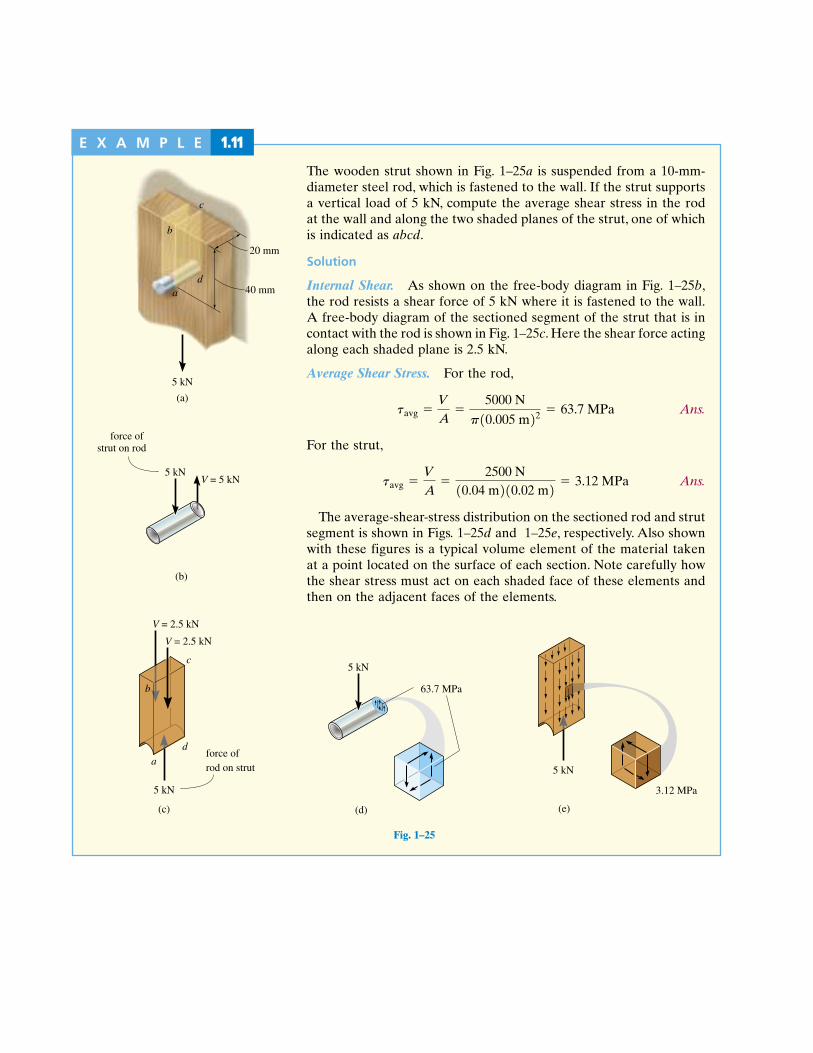
Fig. 1–25eFig. 1–25d
Fig. 1–25b
Fig. 1–25a
E X A M P L E 1.11
The wooden strut shown in Fig. 1–25a is suspended from a 10-mm-diameter steel rod, which is fastened to the wall. If the strut supportsa vertical load of 5 kN, compute the average shear stress in the rodat the wall and along the two shaded planes of the strut, one of whichis indicated as abcd.
Solution
Internal Shear. As shown on the free-body diagram in Fig. 1–25b,the rod resists a shear force of 5 kN where it is fastened to the wall.A free-body diagram of the sectioned segment of the strut that is incontact with the rod is shown in Fig. 1–25c. Here the shear force actingalong each shaded plane is 2.5 kN.
Average Shear Stress. For the rod,
Ans.
For the strut,
Ans.
The average-shear-stress distribution on the sectioned rod and strutsegment is shown in Figs. 1–25d and 1–25e, respectively. Also shownwith these figures is a typical volume element of the material takenat a point located on the surface of each section. Note carefully howthe shear stress must act on each shaded face of these elements andthen on the adjacent faces of the elements.
tavg =V
A=
2500 N10.04 m210.02 m2 = 3.12 MPa
tavg =V
A=
5000 N
p10.005 m22 = 63.7 MPa
c
5 kN
(a)
20 mm
40 mm
b
ad
(b)
5 kNV = 5 kN
force of strut on rod
a
d
c
5 kN
V = 2.5 kN
V = 2.5 kN
force ofrod on strut
(c)
b
Fig. 1–25
(d)
5 kN
63.7 MPa
5 kN
(e)
3.12 MPa
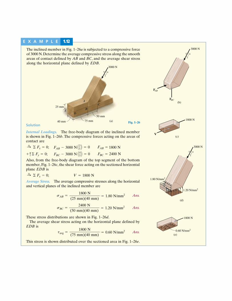
Fig. 1–26e
Fig. 1–26d
Fig. 1–26c
Fig. 1–26b
E X A M P L E 1.12
The inclined member in Fig. 1–26a is subjected to a compressive forceof 3000 N. Determine the average compressive stress along the smoothareas of contact defined by AB and BC, and the average shear stressalong the horizontal plane defined by EDB.
(b)
3
45
3000 N
FAB
FBC
(c)V
1800 N
Solution
Internal Loadings. The free-body diagram of the inclined memberis shown in Fig. 1–26b. The compressive forces acting on the areas ofcontact are
Also, from the free-body diagram of the top segment of the bottommember, Fig. 1–26c, the shear force acting on the sectioned horizontalplane EDB is
Average Stress. The average compressive stresses along the horizontaland vertical planes of the inclined member are
Ans.
Ans.
These stress distributions are shown in Fig. 1–26d.The average shear stress acting on the horizontal plane defined by
EDB is
Ans.
This stress is shown distributed over the sectioned area in Fig. 1–26e.
tavg =360 lb
13 in.211.5 in.2 = 80 psi
sBC =480 lb
12 in.211.5 in.2 = 160 psi
sAB =360 lb
11 in.211.5 in.2 = 240 psi
V = 360 lb:+ © Fx = 0;
FBC - 600 lb A45 B = 0 FBC = 480 lb+q© Fy = 0;
FAB - 600 lb A35 B = 0 FAB = 360 lb:+ © Fx = 0;
3
45
3000 N
1.20 N/mm
1.80 N/mm
(d)
2
2
1800 N
(e)0.60 N/mm2
Fig. 1–26
25 mm
3
45
3000 N
(a)40 mm 75 mm
50 mm
AC
B
DE
1800 N
0.60 N/mm2
FAB 3000 N
1800 N————————(75 mm)(40 mm)
1.80 N/mm21800 N————————(25 mm)(40 mm)
1.20 N/mm22400 N————————(50 mm)(40 mm)
1800 N
2400 NFBC 3000 N

Fig. 1–31b
E X A M P L E 1.13
The two members are pinned together at B as shown in Fig. 1–31a.Top views of the pin connections at A and B are also given in thefigure. If the pins have an allowable shear stress of allow 90 MPaand the allowable tensile stress of rod CB is (t)allow 115 MPa,determine to the nearest mm the smallest diameter of pins A and Band the diameter of rod CB necessary to support the load.
B
2 m
6 kN3
5
4
C
1 m
A
BA
(a)
Fig. 1–31
SolutionRecognizing CB to be a two-force member, the free-body diagram ofmember AB along with the computed reactions at A and B is shownin Fig. 1–31b. As an exercise, verify the computations and notice thatthe resultant force at A must be used for the design of pin A, sincethis is the shear force the pin resists.
2 mA
(b)
6 kN
B1 m
2 kN
6.67 kN
5.68 kN
5.32 kN
20.6°35
4
Continued

Fig. 1–31c
(c)
2.84 kN
2.84 kN
5.68 kN
6.67 kN
6.67 kN
Pin at BPin at A
Diameter of the Pins. From Fig. 1–31a and the free-body diagramsof the sectioned portion of each pin in contact with member AB,Fig. 1–31c, it is seen that pin A is subjected to double shear, whereaspin B is subjected to single shear. Thus,
AA
AB
Although these values represent the smallest allowable pin diameters,a fabricated or available pin size will have to be chosen.We will choosea size larger to the nearest millimeter as required.
dA 7 mm Ans.
dB 10 mm Ans.
Diameter of Rod. The required diameter of the rod throughout itsmidsection is thus,
dBC 8.59 mm
We will choose
dBC 9 mm Ans.
ABC =P
1st2allow=
3.333 kip
16.2 kip>in2 = 0.2058 in2 = padBC2
4b 58 106 m2
6.67 kN——————–115 103 kPa
dBC2
——4( )
31.56 106 m2 dA 6.3 mm2.84 kN
——––——–90 103 kPa
dA2
——4( )VA——–
Tallow
74.11 106 m2 dB 9.7 mm6.67 kN
——––——–90 103 kPa
VB——–Tallow
dB2
——4( )
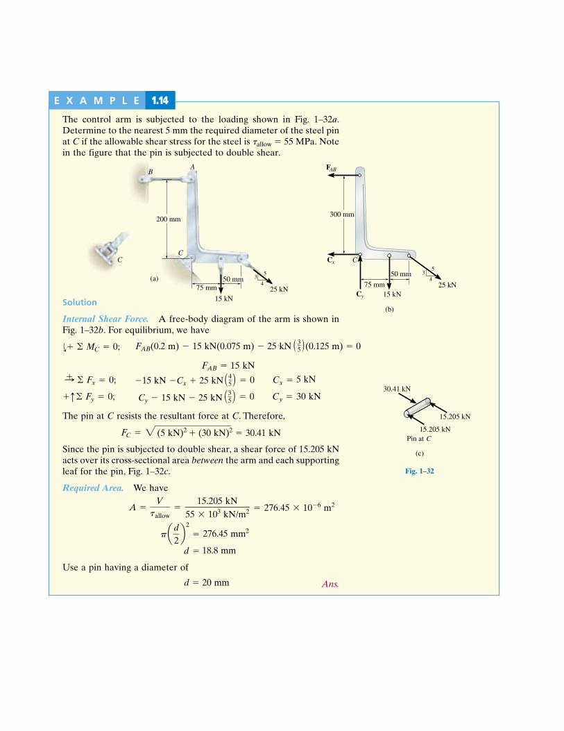
Fig. 1–32aFig. 1–32b
E X A M P L E 1.14
The control arm is subjected to the loading shown in Fig. 1–32a.Determine to the nearest 5 mm the required diameter of the steel pinat C if the allowable shear stress for the steel is allow 55 MPa. Notein the figure that the pin is subjected to double shear.
35
475 mm
300 mm
Cx
15 kN25 kN
FAB
Cy
(b)
C
50 mm
(c)
15.205 kN
15.205 kN
30.41 kN
Pin at C
Fig. 1–32
(a)
C
35
475 mm
200 mm
A
C
15 kN25 kN
B
50 mm
Solution
Internal Shear Force. A free-body diagram of the arm is shown inFig. 1–32b. For equilibrium, we have
FAB 15 kN
The pin at C resists the resultant force at C. Therefore,
Since the pin is subjected to double shear, a shear force of 15.205 kNacts over its cross-sectional area between the arm and each supportingleaf for the pin, Fig. 1–32c.
Required Area. We have
Use a pin having a diameter of
Ans.d = 34 in. = 0.750 in.
d = 0.696 in.
pad2b2
= 0.3802 in2
A =Vtallow
=3.041 kip
8 kip>in2 = 0.3802 in2
FC = 211 kip22 + 16 kip22 = 6.082 kip
Cy - 3 kip - 5 kip A35 B = 0 Cy = 6 kip+q© Fy = 0;
-3 kip - Cx + 5 kip A45 B = 0 Cx = 1 kip:+ © Fx = 0;
d+ © MC = 0;
d 20 mm
276.45 mm2
18.8 mm
276.45 106 m215.205 kN———————55 103 kN/m2
5 kN
(5 kN)2 (30 kN)2 30.41 kN
30 kNCy 15 kN 25 kN
15 kN Cx 25 kN
FAB(0.2 m) 15 kN(0.075 m) 25 kN (0.125 m) 0( )3–5

Fig. 1–33b
E X A M P L E 1.15
The suspender rod is supported at its end by a fixed-connected circulardisk as shown in Fig. 1–33a. If the rod passes through a 40-mm-diameter hole, determine the minimum required diameter of the rodand the minimum thickness of the disk needed to support the 20-kNload. The allowable normal stress for the rod is andthe allowable shear stress for the disk is tallow = 35 MPa.
sallow = 60 MPa,
20 kN
A allow
(b)
40 mm
20 kN
t
d
(a)
40 mm
Fig. 1–33Solution
Diameter of Rod. By inspection, the axial force in the rod is 20 kN.Thus, the required cross-sectional area of the rod is
So that
Ans.
Thickness of Disk. As shown on the free-body diagram of the coresection of the disk, Fig. 1–33b, the material at the sectioned area mustresist shear stress to prevent movement of the disk through the hole.If this shear stress is assumed to be distributed uniformly over thesectioned area, then, since we have
Since the sectioned area the required thicknessof the disk is
Ans.t =0.5714110-32 m2
2p10.02 m2 = 4.55110-32 m = 4.55 mm
A = 2p10.02 m21t2,A =
Vtallow
=2011032 N
3511062 N>m2 = 0.571110-32 m2
V = 20 kN,
d = 0.0206 m = 20.6 mm
A = pad2
4b = 0.3333110-22 m2
A =Psallow
=2011032 N
6011062 N>m2 = 0.3333110-32 m2

Fig. 1–34d
Fig. 1–34bFig. 1–34a
E X A M P L E 1.16
An axial load on the shaft shown in Fig. 1–34a is resisted by the collarat C, which is attached to the shaft and located on the right side ofthe bearing at B. Determine the largest value of P for the two axialforces at E and F so that the stress in the collar does not exceed anallowable bearing stress at C of and the averagenormal stress in the shaft does not exceed an allowable tensile stressof 1st2allow = 55 MPa.
1sb2allow = 75 MPa
PP2
(b)
P380 mm
60 mmP
A
FP2
CE
B
(a)
20 mm
(c)
AxialLoad
Position
3P2P
Fig. 1–34
SolutionTo solve the problem we will determine P for each possible failurecondition. Then we will choose the smallest value. Why?
Normal Stress. Using the method of sections, the axial load withinregion FE of the shaft is 2P, whereas the largest axial load, 3P, occurswithin region EC, Fig. 1–34b. The variation of the internal loading isclearly shown on the normal-force diagram, Fig. 1–34c. Since the cross-sectional area of the entire shaft is constant, region EC will be subjectedto the maximum average normal stress. Applying Eq. 1–11, we have
Bearing Stress. As shown on the free-body diagram in Fig. 1–34d,the collar at C must resist the load of 3P, which acts over a bearingarea of Thus,
By comparison, the largest load that can be applied to the shaft issince any load larger than this will cause the allowable
normal stress in the shaft to be exceeded.P = 51.8 kN,
P = 55.0 kN
7511062 N>m2 =3P
2.199110-32 m2A =Psallow
;
Ab = [p10.04 m22 - p10.03 m22] = 2.199110-32 m2.
P = 51.8 kN
sallow =P
A 5511062 N>m2 =
3P
p10.03 m22
P3
(d)C

Fig. 1–35a
E X A M P L E 1.17
The rigid bar AB shown in Fig. 1–35a is supported by a steel rod AChaving a diameter of 20 mm and an aluminum block having a cross-sectional area of The 18-mm-diameter pins at A and C aresubjected to single shear. If the failure stress for the steel and aluminumis and respectively, and thefailure shear stress for each pin is determine the largestload P that can be applied to the bar.Apply a factor of safety of
SolutionUsing Eqs. 1–9 and 1–10, the allowable stresses are
The free-body diagram for the bar is shown in Fig. 1–35b. There arethree unknowns. Here we will apply the equations of equilibrium so asto express and in terms of the applied load P. We have
(1)
(2)
We will now determine each value of P that creates the allowable stressin the rod, block, and pins, respectively.Rod AC. This requires
Using Eq. 1,
Block B. In this case,
Using Eq. 2,
Pin A or C. Here
From Eq. 1,
By comparison, when P reaches its smallest value (168 kN), it developsthe allowable normal stress in the aluminum block. Hence,
Ans.P = 168 kN
P =114.5 kN12 m2
1.25 m= 183 kN
V = FAC = tallowA = 45011062 N>m2[p10.009 m22] = 114.5 kN
P =163.0 kN212 m2
0.75 m= 168 kN
FB = 1sal2allow AB = 3511062 N>m2[1800 mm2110-62 m2>mm2] = 63.0 kN
P =1106.8 kN212 m2
1.25 m= 171 kN
FAC = 1sst2allow1AAC2 = 34011062 N>m2[p10.01 m22] = 106.8 kN
FB12 m2 - P10.75 m2 = 0d+ © MA = 0;
P11.25 m2 - FAC12 m2 = 0d+ © MB = 0;
FBFAC
tallow =tfail
F.S.=
900 MPa2
= 450 MPa
1sal2allow =1sal2fail
F.S.=
70 MPa2
= 35 MPa
1sst2allow =1sst2fail
F.S.=
680 MPa2
= 340 MPa
F.S. = 2.tfail = 900 MPa,
1sal2fail = 70 MPa,1sst2fail = 680 MPa
1800 mm2.
2 m
A
0.75 m
(a)
Aluminum
Steel P
B
C
A
0.75 m
(b)
P
1.25 m
B
FB
FAC
Fig. 1–35