Examination of the 1970 National Bureau of Standards Underground Corrosion Test Welded...
64
The INL is a U.S. Department of Energy National Laboratory operated by Battelle Energy Alliance INL/EXT-07-13015 Examination of the 1970 National Bureau of Standards Underground Corrosion Test Welded Stainless Steel Coupons from Site D L. R. Zirker M. K. Adler Flitton T. S. Yoder T. L. Trowbridge January 2008
Transcript of Examination of the 1970 National Bureau of Standards Underground Corrosion Test Welded...

The INL is a U.S. Department of Energy National Laboratory operated by Battelle Energy Alliance
INL/EXT-07-13015
Examination of the 1970 National Bureau of Standards Underground Corrosion Test Welded Stainless Steel Coupons from Site D
L. R. Zirker M. K. Adler Flitton T. S. Yoder T. L. Trowbridge
January 2008

INL/EXT-07-13015
Examination of the 1970 National Bureau of Standards Underground Corrosion Test Welded Stainless Steel
Coupons from Site D
L. R. Zirker M. K. Adler Flitton
T. S. Yoder T. L. Trowbridge
January 2008
Idaho National Laboratory Environmental Management Science Program
Idaho Falls, Idaho 83415
Prepared for the U.S. Department of Energy
Assistant Secretary for Environmental Management Under DOE Idaho Operations Office
Contract DE-AC07-05ID14517

DISCLAIMER This information was prepared as an account of work sponsored by an
agency of the U.S. Government. Neither the U.S. Government nor any agency thereof, nor any of their employees, makes any warranty, expressed or implied, or assumes any legal liability or responsibility for the accuracy, completeness, or usefulness, of any information, apparatus, product, or process disclosed, or represents that its use would not infringe privately owned rights. References herein to any specific commercial product, process, or service by trade name, trade mark, manufacturer, or otherwise, does not necessarily constitute or imply its endorsement, recommendation, or favoring by the U.S. Government or any agency thereof. The views and opinions of authors expressed herein do not necessarily state or reflect those of the U.S. Government or any agency thereof.


Examination of the 1970 National Bureau of Standards Underground INL/EXT-07-13015 Corrosion Test Welded Stainless Steel Coupons from Site D January 2008
iii
EXECUTIVE SUMMARY
A 1970 study initiated by the National Bureau of Standards (NBS), now known as the National Institute of Standards and Technology (NIST), buried over 6000 corrosion coupons or specimens of stainless steel Types 201, 202, 301, 304, 316, 409, 410, 430, and 434. The coupons were configured as sheet metal plates, coated plates, cross-welded plates, U-bend samples, sandwiched materials, and welded tubes. All coupons were of various heat-treatments and cold worked conditions and were buried at six distinctive soil-type sites throughout the United States. The NBS scientists dug five sets of two trenches at each of the six sites. In each pair of trenches, they buried duplicate sets of stainless steel coupons. The NBS study was designed to retrieve coupons after one year, two years, four years, eight years, and x years in the soil. During the first eight years of the study, four of five planned removals were completed. After the fourth retrieval, the NBS study was abandoned, and the fifth and final set of specimens remained undisturbed for over 33 years.
In 2003, an interdisciplinary research team of industrial, university, and national laboratory investigators were funded under the United States Department of Energy’s Environmental Management Science Program (EMSP; Project Number 86803) to extract part of the remaining set of coupons at one of the test sites, characterize the stainless steel underground corrosion rates, and examine the fate and transport of metal ions into the soil. Extraction of one trench at one of the test sites occurred in April 2004.
This report details only the characterization of corrosion found on the 14 welded coupons–two cross welded plates, six U-bends, and six welded tubes–that were retrieved from Site D, located near Wildwood, NJ. The welded coupons included Type 301, 304, 316, and 409 stainless steels. After 33 years in the soil, corrosion on the coupons varied according to alloy. This report discusses the stress corrosion cracking and crevice corrosion cracking of the U-bend coupons; the minimal corrosion found on the cross-bead plates; and the general, pitting, and crevice corrosion found on the welded tubes. In general, the austenitic Type 301, 304 and 316 samples showed little if any corrosion after 33+-years in the soil, whereas the ferritic alloys-Type 409 and 434– showed a spectrum of corrosion.

Examination of the 1970 National Bureau of Standards Underground INL/EXT-07-13015 Corrosion Test Welded Stainless Steel Coupons from Site D January 2008
iv
Examination of the 1970 National Bureau of Standards Underground INL/EXT-07-13015 Corrosion Test Welded Stainless Steel Coupons from Site D January 2008
v
CONTENTS
EXECUTIVE SUMMARY ......................................................................................................................... iii
ACRONYMS.............................................................................................................................................viii
1. RESEARCH BACKGROUND .......................................................................................................... 1
2. REVIVING THE NBS STUDY......................................................................................................... 1
3. STARTING THE RESEARCH.......................................................................................................... 23.1 Site D ....................................................................................................................................... 23.2 Site D Trenches........................................................................................................................ 33.3 Site D 1970 Coupons ............................................................................................................... 33.4 Site D 1970 Welded Coupon Numbering Methodology.......................................................... 33.5 Site D 1970 Coupon Retrieval ................................................................................................. 43.6 Site D 1970 Welded Coupons .................................................................................................. 63.7 Field Photographs of the Site D 1970 Welded Coupons.......................................................... 8
4. Characterization of Corrosion on the Welded Stainless Steel Coupons........................................... 124.1 Corrosion on Welded Double U-bend Samples ..................................................................... 12
4.1.1 Scanning Electron Microscope Microscopy Analysis .............................................. 124.1.2 Scanning Electron Microscope Photographs of Resistance Spot Welds................... 124.1.3 Cross Sections of Double U-bend Spot Welds ......................................................... 17
4.2 Corrosion on Cross Bead Plate Coupons ............................................................................... 214.3 Corrosion on Welded Tube Coupons..................................................................................... 24
4.3.1 System 57, Type 304 Tubes...................................................................................... 244.3.2 System 62, Type 409 Tubes...................................................................................... 264.3.3 System 63, Type 409 Tubes...................................................................................... 28
4.4 Comparison between 1981 NBS and INL Corrosion Analysis.............................................. 30
5. Significance of the Research ............................................................................................................ 315.1 Benefits of Subsequent Research ........................................................................................... 31
6. Conclusions ...................................................................................................................................... 31
7. References ........................................................................................................................................ 33
Appendix A Final Report: Corrosion Behavior of Welded Stainless Steels in Soil Environments
FIGURESFigure 1. Typical trench with new coupons in the trench and retrieved coupons on the bank. ................... 1
Figure 2. Old sign marking the site.............................................................................................................. 3
Figure 3. Looking west in January. Florescent paint marks the post locations............................................ 3
Figure 4. Looking south at the posts in June after some of the underbrush was removed........................... 3

Examination of the 1970 National Bureau of Standards Underground INL/EXT-07-13015 Corrosion Test Welded Stainless Steel Coupons from Site D January 2008
vi
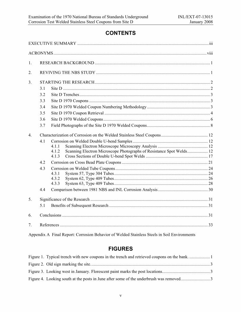
Figure 5. Site D is located 30 feet beyond the edge of the trees and brush. ................................................ 4
Figure 6. Excavation team from left to right are Kathy Counts, SRNL, Carolyn Bishop and Kay Adler-Flitton of INL. .................................................................................................................... 5
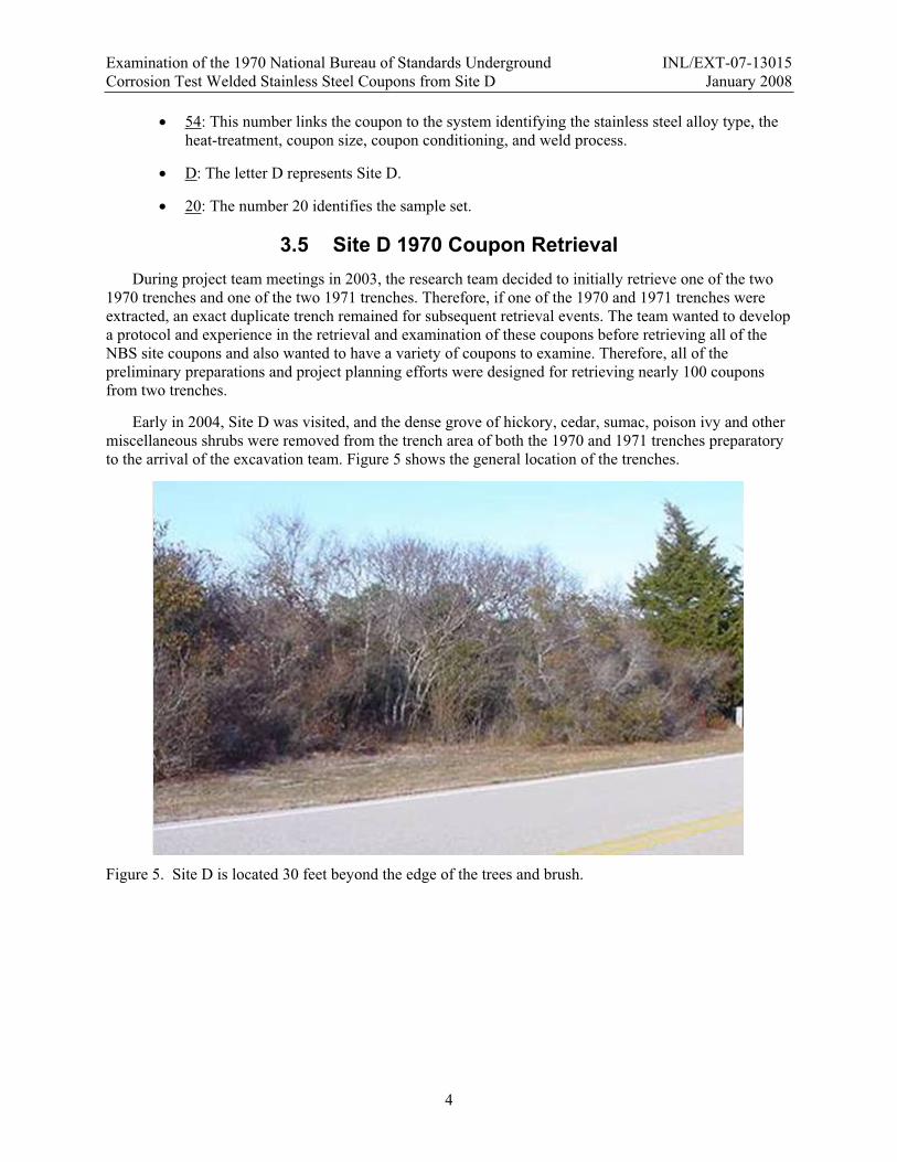
Figure 7. Looking south at 1971 trench on the left and 1970 on the right prior to excavation.................... 5
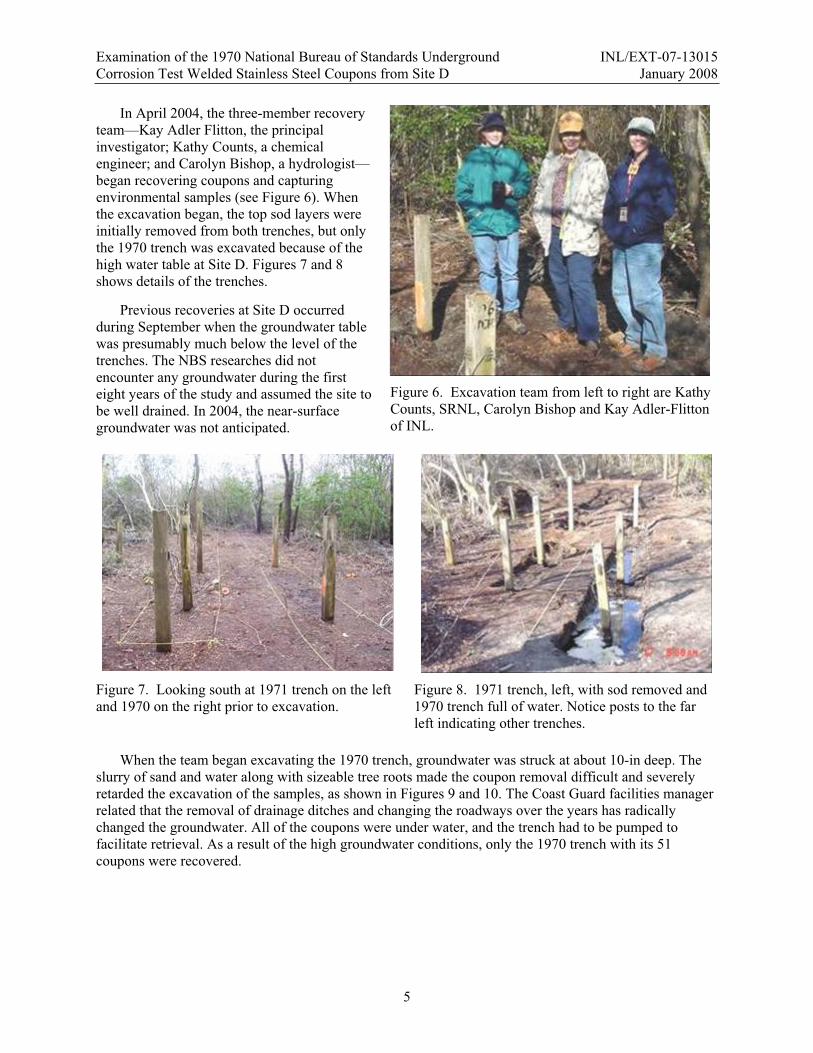
Figure 8. 1971 trench, left, with sod removed and 1970 trench full of water. Notice posts to the far left indicating other trenches. .................................................................................................. 5
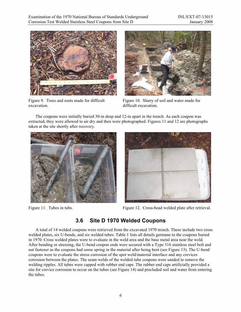
Figure 9. Trees and roots made for difficult excavation. ............................................................................. 6
Figure 10. Slurry of soil and water made for difficult excavation. .............................................................. 6
Figure 11. Tubes in tubs............................................................................................................................... 6
Figure 12. Cross-bead welded plate after retrieval. ..................................................................................... 6
Figure 13. Stressed U-bend coupon. ............................................................................................................ 8
Figure 14. Rubber caps on tube coupons. .................................................................................................... 8
Figure 15. Front side cross-welded plate, sample 54D19 (Type 301). ........................................................ 8
Figure 16. Backside cross-welded plate, sample 54D19 (Type 301)........................................................... 8
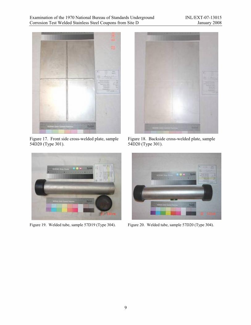
Figure 17. Front side cross-welded plate, sample 54D20 (Type 301). ........................................................ 9
Figure 18. Backside cross-welded plate, sample 54D20 (Type 301)........................................................... 9
Figure 19. Welded tube, sample 57D19 (Type 304). ................................................................................... 9
Figure 20. Welded tube, sample 57D20 (Type 304). ................................................................................... 9
Figure 21. Welded tube, sample 62D19 (Type 409). ................................................................................. 10
Figure 22. Welded tube, sample 62D20 (Type 409). ................................................................................. 10
Figure 23. Welded tube, sample 63D19 (Type 409). ................................................................................. 10
Figure 24. Welded tube, sample 63D20 (Type 409). ................................................................................. 10
Figure 25. U-bend coupon, sample 68D20 (Type 301). ............................................................................ 10
Figure 26. U-bend coupon, sample 71D20 (Type 301). ............................................................................ 10
Figure 27. U-bend coupon, sample 73D20 (Type 304). ............................................................................ 11
Figure 28. U-bend coupon, sample 75D20 (Type 304). ............................................................................ 11
Figure 29. U-bend coupon, sample 78D20 (Type 316). ............................................................................ 11
Figure 30. U-bend coupon, sample 81D20 (Type 434). ............................................................................ 11
Figure 31. System 68 (Type 301) ESEM 25X photograph of spot weld. ................................................... 13
Figure 32. System 68, this optical photograph shows the basic size of the melted spot weld in relationship to the expulsions. This photograph shows the actual spot weld size or “nugget” better than the ESEM photograph. .............................................................................. 13
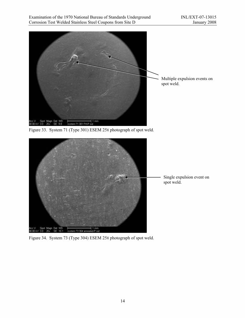
Figure 33. System 71 (Type 301) ESEM 25X photograph of spot weld. ................................................... 14
Figure 34. System 73 (Type 304) ESEM 25X photograph of spot weld. ................................................... 14
Figure 35. System 75 (Type 304) ESEM 25X photograph of spot weld. ................................................... 15
Figure 36. System 78 (Type 316) ESEM 25X photograph of spot weld. ................................................... 15

Examination of the 1970 National Bureau of Standards Underground INL/EXT-07-13015 Corrosion Test Welded Stainless Steel Coupons from Site D January 2008
vii
Figure 37. System 81 (Type 434) ESEM 25X photograph of spot weld. ................................................... 16
Figure 38. Back Scatter Electron image of System 81 (Type 434)............................................................ 17
Figure 39. System 68 (Type 301) 25X photograph of cross section. No corrosion visible. ....................... 17
Figure 40. System 68 (Type 301) 100X photograph of expulsion. ............................................................ 18
Figure 41. System 71 (Type 301) 25X photograph of cross section with large shrinkage void. No corrosion visible. ........................................................................................................................ 18
Figure 42. System 73 (Type 304) 25X photograph of cross section with small shrinkage voids. No corrosion visible.................................................................................................................... 19
Figure 43. System 75 (Type 304) 25X photograph of cross section with small shrinkage voids. No corrosion visible.................................................................................................................... 19
Figure 44. System 78 (Type 316) 25X photograph of cross section with large shrinkage voids. No corrosion visible. ........................................................................................................................ 20
Figure 45. System 81 (Type 434) 25X photograph of cross section with severe corrosion. ...................... 20
Figure 46. Close-up top view of end of weld at edge of plate on sample 54D20. ..................................... 21
Figure 47. Close-up end view of plate at the beginning point of weld on sample 54D20. ........................ 21
Figure 48. Locations on plates where pits were located and where sections were removed. .................... 22
Figure 49. End view of cross sectioned weld about 1-in from the edge of the plate, sample 54D19. ........................................................................................................................................ 22
Figure 50. Tunneling corrosion in the weld metal. .................................................................................... 23
Figure 51. Tunneling corrosion was into the base metal. .......................................................................... 23
Figure 52. System 57, Type 304 GTAW welded coupon with removed rubber stopper. .......................... 24
Figure 53. System 57 collages, coupons 57D19 and 57D20...................................................................... 25
Figure 54. 10X photograph of corrosion on sample 62D19 weld. Weld is the sanded surface.................. 26
Figure 55. 10X photograph of general and crevice corrosion sample 62D19. ........................................... 26
Figure 56. System 62 collages, coupons 62D19 and 62D20...................................................................... 27
Figure 57. 10X photograph of general and crevice corrosion sample 63D19. ........................................... 28
Figure 58. 30X photograph of preferential corrosion attach along scratches on weld of sample 63D19. ........................................................................................................................................ 28
Figure 59. System 63 collages, coupons 63D19 and 63D20...................................................................... 29
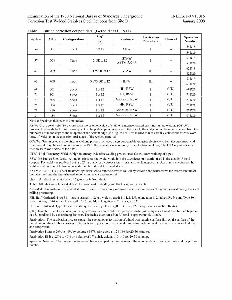
TABLESTable 1. Buried corrosion coupon data. (Gerhold et al., 1981).................................................................... 7
Table 2. Comparison between NBS report (Gerhold et al., 1981) and the INL analysis........................... 30
Examination of the 1970 National Bureau of Standards Underground INL/EXT-07-13015 Corrosion Test Welded Stainless Steel Coupons from Site D January 2008
viii
ACRONYMSASTM American Society for Testing and Materials
BSE Back Scatter Electron
DOE US Department of Energy
EDS Energy Dispersive Spectrometer
EMSP Environmental Management Science Program
ESEM Environmental Scanning Electron Microscope
FH Full hardened
GTAW gas tungsten arc welding
HAZ Heat affected zone
HFW High frequency weld
HH Half hardened
INL Idaho National Laboratory
NBS National Bureau of Standards
NIST National Institute of Standards and Technology
OSU Ohio State University
RSW Resistance Spot Welding
SRNL Savannah River National Laboratory
(UU) Double U-bend with a resistance spot weld
XBW Cross bead weld

Examination of the 1970 National Bureau of Standards Underground INL/EXT-07-13015 Corrosion Test Welded Stainless Steel Coupons from Site D January 2008
1
1. RESEARCH BACKGROUND In 1970 the National Bureau of Standards (NBS), now known as the National Institute of Standards
and Technology (NIST), initiated an underground corrosion study of stainless steel at six test sites. (Gerhold et al., 1981) The stainless steel coupons–Types 201, 202, 301, 304, 316, 409, 410, 430, and 434–were configured as plates, U-bends, and welded tubes of various heat-treatment and cold worked conditions. In 1971 and 1972, additional stainless steel alloys were included into the long-term underground corrosion study. From 1970 to 1972, the NBS buried a total of 6,456 coupons at six distinctive soil-type sites throughout the United States.
The NBS study was designed to retrieve coupons after one year, two years, four years, eight years, and x years in the soil. An interesting aspect of the study was that the NBS scientist recycled the trenches. When they retrieved the first batch of coupons after one year, they placed more coupons (the 1971 samples) into the open trench prior to backfilling the trench. Then with the two-year retrieval campaign, they placed additional coupons (the 1972 samples) into the trenches before backfilling. Figure 1, a 1932 NBS photograph, shows the retrieved coupons on the bank and the new coupons in the trench. This photograph accurately depicts the reuse of test trenches since this 1932 test site is also one of the test sites used for the 1970 underground corrosion study.
During the first eight years of the study, four of five planned removals were completed with specimens retrieved after one, two, four, and eight years at each of the six sites. After the eight-year retrieval, the NBS changed from fundamental research to more analytical research areas, and the fifth and final set of specimens remained undisturbed for over 33 years. The underground corrosion study was essentially abandoned by NBS.
2. REVIVING THE NBS STUDY As of 2007, two of the three NBS principal investigators are deceased. Metallurgist Edward
Escalante, the remaining principal investigator, was instrumental in resurrecting the study. In 1996, Escalante was hired as a consultant to review a proposed long-term underground corrosion project at the U.S. Department of Energy (DOE) Idaho National Laboratory (INL). The goal of the INL’s project was to obtain long-term site-specific underground corrosion rates and apply the rates to buried radioactive waste disposal facility performance assessment modeling.
During his visit to the INL, Escalante mentioned to Larry Zirker, the initial project engineer, about the abandoned NBS study. Over the next six-years, the abandoned NBS study was a frequent topic of conversation between Larry Zirker and Kay Adler-Flitton, an INL corrosion scientist, and Dr. Macintyre Louthan, metallurgist from the DOE Savannah River National Laboratory (SRNL) in South Carolina. The NBS underground corrosion study was viewed as an analogy to buried radioactive waste containers and nuclear waste degradation at several of DOE’s disposal facilities across the United States. In 2002, the three wrote a proposal to the DOE Environmental Management Science Program (EMSP) to obtain permission from NIST and the original sponsor or owner of the coupons, American Iron and Steel Institute, to revive the research and to retrieve the coupons from one site.
Figure 1. Typical trench with new coupons in the trench and retrieved coupons on the bank.

Examination of the 1970 National Bureau of Standards Underground INL/EXT-07-13015 Corrosion Test Welded Stainless Steel Coupons from Site D January 2008
2
In 2003, an ambitious interdisciplinary research team of industrial, university, and national laboratory investigators were funded under an EMSP research grant (Project Number 86803) to retrieve part of the coupons and unraveled the complicated interrelationships among metal integrity, corrosion rates, corrosion mechanisms, soil properties, soil microbiology, plant and animal interaction with corrosion products, and fate and transport of metallic ions into the soil.
3. STARTING THE RESEARCH Early in 2003, initial investigations at each of the six NBS test sites were conducted and a dialog was
established with the individual site landlords. None of the current landlords had any first hand knowledge of the NBS study. All of the sites were visited and the trenches were located except for those trenches at Site G. Site G, adjacent to the Patuxent Navel Air Station near Lexington Park, MD, along a tidal marsh, was dredged a few years ago the Army Corp of Engineers and all of the Site G coupons were lost.
The initial site chosen by the research team was Site A, near Toppenish, WA. Site A has the Sagemoor Sandy Loam soil that most closely matches the soils at DOE’s Idaho and Washington radioactive waste disposal facilities. Permission to retrieve the coupons from Site A was not forthcoming, so an alternative NBS test site was selected as the initial research target.
The research team selected Site D as the target site. A leading reason behind selecting Site D was that the trench locations at Site D were still clearly marked with posts. After nearly 34-years, the posts marking the trenches at other sites were not as well preserved. A map of Site D was also recovered as one of the surviving records at NIST. The landlord is very supportive and gave permission to the research team to excavate and recover the coupons. Also, the site is analog for DOE’s South Carolina’s radioactive waste disposal facility.
3.1 Site D Site D is located on the property and within the security fence of the U.S. Coast Guard Loran Support
Unit Station south of Wildwood, N.J., near the southern tip of New Jersey. The soil at Site D is a Lakewood Sand—white, loose sand with some black streaks occurring in places—and supports an abundant growth of beach grasses. The sand has a pH of 5.7 and a resistivity range from 13,800 to 57,500 ohm-cm. Site D is located 500 yards off of the actual Atlantic Ocean coast line and is not subjected to ocean water except in extreme and unusual flood conditions. (Gerhold et al., 1981)
Site D has radically changed since the burial of the coupons in September 1970. Initially, the site was located on a flat grassy location west of the main road and south of the security gate on Coast Guard site. Over the years, the site turned into a virtual grove of trees, bushes, and poisonous vines. Also, since 1970, placement of paved roads and the elimination of maintained drainage ditches have altered the hydrology of the site, which exacerbated the change.
The facilities manager at the Coast Guard Station knew the general location of the buried coupons because of some knocked over signs marked the general area, but he never ventured into the forest area beyond the signs to notice the decaying 4 4-in posts marking the trenches. Figures 2, 3, and 4 show the conditions of Site D in 2003.

Examination of the 1970 National Bureau of Standards Underground INL/EXT-07-13015 Corrosion Test Welded Stainless Steel Coupons from Site D January 2008
3
Figure 2. Old sign marking the site.
Figure 3. Looking west in January. Florescent paint marks the post locations.
Figure 4. Looking south at the posts in June after some of the underbrush was removed.
3.2 Site D Trenches All trenches were initially dug with a backhoe to be 30-in deep and 24-in wide. There are three sets of
two trenches remaining with coupons at site D: 1970, 1971, and 1972. Each pair of trenches has identical sample sets of coupons. The trenches are readily identified by the 4 4-in posts that remain in reasonable condition.
3.3 Site D 1970 Coupons There were 51 stainless steel coupons in each of the 1970 trenches. The stainless steel alloys used
were Types 201, 202, 301, 304, 316, 409, 410, 430, and 434. These were the alloys that were readily available for use by industry in 1970 for underground applications (the 1971 and 1972 alloy list was expanded to include other austenitic and specialty alloys). The coupons were configured as sheet metal plates, coated plates, cross-welded plates, U-bends, and welded tubes. All coupons were of various heat-treatment and cold worked conditions.
The sheet metal plates were sheared to size and then deburred. The cross-welded plate and the tube materials were degreased in trichloroethylene vapor, passivated, scrubbed with a fiber brush, thoroughly rinsed with water, and then air dried. The U-bend coupons were first sheared to size, deburred, and punched for a restraining bolt. Then, the strips of selected coupons were spot welded together, mechanically formed into the U shape, and secured with a bolt. After forming, the U-bend coupons were cleaned and then given the passivation treatment.
The coupons were placed 30-in deep in the trench and 12-in apart. The 8 12-in cross-welded plates were buried on edge with the 8-in edge horizontal. The tubes were placed horizontal with the bottom of the trench, and the U-bend coupons were likewise placed flat, with one edge of the strips placed on the bottom of the trench. A thick nylon string was tethered from a 4 4-in post to each of the six U-bend samples to aid in the retrieval of these coupons.
3.4 Site D 1970 Welded Coupon Numbering Methodology The report issued by NBS in 1981 on the eight-year retrieval effort (Gerhold et al., 1981), details the
burial order of the coupons in the trench. 4 4-in cedar wood posts were used to mark the trench locations and the position of the coupons in the trenches. Each coupon has a unique identification code number stamped on it. The 0.125-in tall letters and numbers have three parts or identifiers: the system, the site, and the sample set number. A typical number would be 54D20. An interpretation of the coupon number “54D20” includes:
Examination of the 1970 National Bureau of Standards Underground INL/EXT-07-13015 Corrosion Test Welded Stainless Steel Coupons from Site D January 2008
4
54: This number links the coupon to the system identifying the stainless steel alloy type, the heat-treatment, coupon size, coupon conditioning, and weld process.
D: The letter D represents Site D.
20: The number 20 identifies the sample set.
3.5 Site D 1970 Coupon Retrieval During project team meetings in 2003, the research team decided to initially retrieve one of the two
1970 trenches and one of the two 1971 trenches. Therefore, if one of the 1970 and 1971 trenches were extracted, an exact duplicate trench remained for subsequent retrieval events. The team wanted to develop a protocol and experience in the retrieval and examination of these coupons before retrieving all of the NBS site coupons and also wanted to have a variety of coupons to examine. Therefore, all of the preliminary preparations and project planning efforts were designed for retrieving nearly 100 coupons from two trenches.
Early in 2004, Site D was visited, and the dense grove of hickory, cedar, sumac, poison ivy and other miscellaneous shrubs were removed from the trench area of both the 1970 and 1971 trenches preparatory to the arrival of the excavation team. Figure 5 shows the general location of the trenches.
Figure 5. Site D is located 30 feet beyond the edge of the trees and brush.
Examination of the 1970 National Bureau of Standards Underground INL/EXT-07-13015 Corrosion Test Welded Stainless Steel Coupons from Site D January 2008
5
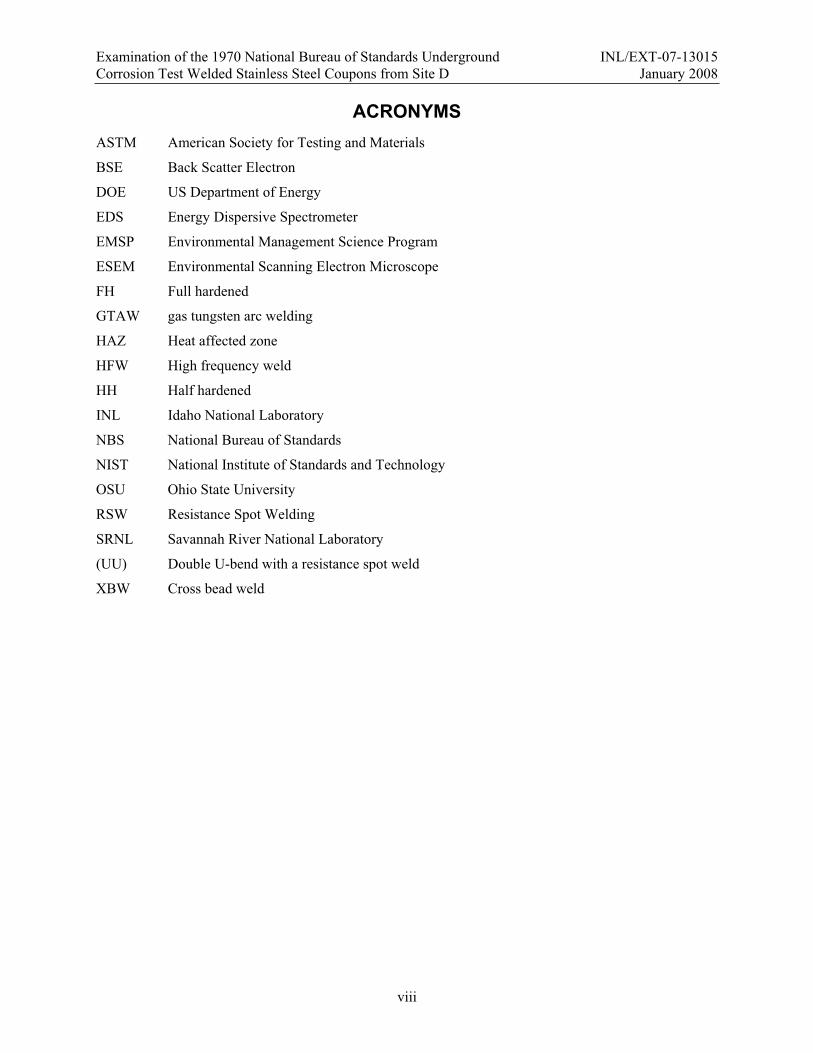
In April 2004, the three-member recovery team—Kay Adler Flitton, the principal investigator; Kathy Counts, a chemical engineer; and Carolyn Bishop, a hydrologist—began recovering coupons and capturing environmental samples (see Figure 6). When the excavation began, the top sod layers were initially removed from both trenches, but only the 1970 trench was excavated because of the high water table at Site D. Figures 7 and 8 shows details of the trenches.
Previous recoveries at Site D occurred during September when the groundwater table was presumably much below the level of the trenches. The NBS researches did not encounter any groundwater during the first eight years of the study and assumed the site to be well drained. In 2004, the near-surface groundwater was not anticipated.
Figure 6. Excavation team from left to right are Kathy Counts, SRNL, Carolyn Bishop and Kay Adler-Flitton of INL.
Figure 7. Looking south at 1971 trench on the left and 1970 on the right prior to excavation.
Figure 8. 1971 trench, left, with sod removed and 1970 trench full of water. Notice posts to the far left indicating other trenches.
When the team began excavating the 1970 trench, groundwater was struck at about 10-in deep. The slurry of sand and water along with sizeable tree roots made the coupon removal difficult and severely retarded the excavation of the samples, as shown in Figures 9 and 10. The Coast Guard facilities manager related that the removal of drainage ditches and changing the roadways over the years has radically changed the groundwater. All of the coupons were under water, and the trench had to be pumped to facilitate retrieval. As a result of the high groundwater conditions, only the 1970 trench with its 51 coupons were recovered.
Examination of the 1970 National Bureau of Standards Underground INL/EXT-07-13015 Corrosion Test Welded Stainless Steel Coupons from Site D January 2008
6
Figure 9. Trees and roots made for difficult excavation.
Figure 10. Slurry of soil and water made for difficult excavation.
The coupons were initially buried 30-in deep and 12-in apart in the trench. As each coupon was extracted, they were allowed to air dry and then were photographed. Figures 11 and 12 are photographs taken at the site shortly after recovery.
Figure 11. Tubes in tubs. Figure 12. Cross-bead welded plate after retrieval.
3.6 Site D 1970 Welded Coupons A total of 14 welded coupons were retrieved from the excavated 1970 trench. These include two cross
welded plates, six U-bends, and six welded tubes. Table 1 lists all details germane to the coupons buried in 1970. Cross welded plates were to evaluate in the weld area and the base metal area near the weld. After bending or stressing, the U-bend coupon ends were secured with a Type 316 stainless steel bolt and nut fastener as the coupons had some spring in the material after being bent (see Figure 13). The U-bend coupons were to evaluate the stress corrosion of the spot weld/material interface and any crevices corrosion between the plates. The seam welds of the welded tube coupons were sanded to remove the welding ripples. All tubes were capped with rubber end caps. The rubber end caps artificially provided a site for crevice corrosion to occur on the tubes (see Figure 14) and precluded soil and water from entering the tubes.
Examination of the 1970 National Bureau of Standards Underground INL/EXT-07-13015 Corrosion Test Welded Stainless Steel Coupons from Site D January 2008
7
Table 1. Buried corrosion coupon data. (Gerhold et al., 1981)
System Alloy Configuration Sizea
(in)Treatment Passivation
Procedure Stressed Specimen Number 54D19
54 301 Sheet 8 12 XBW I -- 54D2057D19
57 304 Tube 2 OD 12 GTAWASTM A-249 I --
57D2062D19
62 409 Tube 1.125 OD 12 GTAW III -- 62D2063D19
63 409 Tube 0.875 OD 12 HFW III -- 63D20
68 301 Sheet 1 12 HH, RSW I (UU) 68D2071 301 Sheet 1 12 FH, RSW I (UU) 71D2073 304 Sheet 1 12 Annealed, RSW I (UU) 73D2075 304 Sheet 1 12 HH, RSW I (UU) 75D2078 316 Sheet 1 12 Annealed, RSW I (UU) 78D2081 434 Sheet 1 12 Annealed, RSW I (UU) 81D20
Note a: Specimen thickness is 0.06 inches XBW: Cross bead weld. Two cross-plate welds on one side of a plate using mechanized gas tungsten arc welding (GTAW) process. The welds laid from the mid-point of the plate edge on one side of the plate to the midpoint on the other side and from the midpoint of the top edge to the midpoint of the bottom edge (see Figure 12). Test is used to measure any deleterious affects, over time, of welding on the corrosion resistance of the welded material. GTAW: Gas tungsten arc welding. A welding process that uses a non-consumable tungsten electrode to heat the base metal and filler wire during the welding operations. In 1970 the process was commonly called Heliarc Welding. The GTAW process was used to seam weld some of the tubes. HFW: High Frequency Weld. A high frequency induction welding process used for the seam-welding of pipes. RSW: Resistance Spot Weld. A single resistance spot weld would join the two pieces of material used in the double U-bend coupon. The weld was produced using 0.25-in diameter electrodes and a resistance welding process. On stressed specimens, the weld was at mid-point between the ends and the sides of the metal strips ASTM A-249: This is a heat-treatment specification to remove stresses caused by welding and restructures the microstructure ofboth the weld and the heat-affected zone to that of the base material. Sheet: All sheet metal pieces are 16 gauge or 0.06-in thick. Tube: All tubes were fabricated from the same material (alloy and thickness) as the sheets. Annealed: The material was annealed prior to use. The annealing removes the stresses in the sheet material caused during the sheetrolling processing.HH: Half Hardened. Type 301 (tensile strength 162 ksi, yield strength 116 ksi, 25% elongation in 2 inches, Rc 34) and Type 304 tensile strength 144 ksi, yield strength 129.3 ksi, 14% elongation in 2 inches, Rc 33) FH: Full Hardened. Type 301 (tensile strength 203 ksi, yield strength 174.7 ksi, 9% elongation in 2 inches, Rc 44) (UU): Double U-bend specimen, joined by a resistance spot weld. Two pieces of metal joined by a spot weld then formed together in a U-bend held by a restraining fastener. The inside diameter of the U-bend is approximately 1 inch. Passivation: The passivation process causes the spontaneous formation of a hard non-reactive surface film on the surface of themetal that inhibits further corrosion. The parts were placed into nitric acid passivation solution and processed at a prescribed time and temperature. Passivation I was at 20% to 40% by volume of 67% nitric acid at 120-160 for 20-30 minutes. Passivation III is at 20% to 40% by volume of 67% nitric acid at 110-140 for 20-30 minutes. Specimen Number: The unique specimen number is stamped on the specimen. The number shows the system, site and coupon set number.

Examination of the 1970 National Bureau of Standards Underground INL/EXT-07-13015 Corrosion Test Welded Stainless Steel Coupons from Site D January 2008
8
Figure 13. Stressed U-bend coupon. Figure 14. Rubber caps on tube coupons.
3.7 Field Photographs of the Site D 1970 Welded Coupons After each of the 14 coupons was recovered, they were air dried and then photographed (see Figures
15 to 30).
Figure 15. Front side cross-welded plate, sample 54D19 (Type 301).
Figure 16. Backside cross-welded plate, sample 54D19 (Type 301).
Examination of the 1970 National Bureau of Standards Underground INL/EXT-07-13015 Corrosion Test Welded Stainless Steel Coupons from Site D January 2008
9
Figure 17. Front side cross-welded plate, sample 54D20 (Type 301).
Figure 18. Backside cross-welded plate, sample 54D20 (Type 301).
Figure 19. Welded tube, sample 57D19 (Type 304). Figure 20. Welded tube, sample 57D20 (Type 304).

Examination of the 1970 National Bureau of Standards Underground INL/EXT-07-13015 Corrosion Test Welded Stainless Steel Coupons from Site D January 2008
10
Figure 21. Welded tube, sample 62D19 (Type 409). Figure 22. Welded tube, sample 62D20 (Type 409).
Figure 23. Welded tube, sample 63D19 (Type 409). Figure 24. Welded tube, sample 63D20 (Type 409).
Figure 25. U-bend coupon, sample 68D20 (Type 301). Figure 26. U-bend coupon, sample 71D20 (Type 301).

Examination of the 1970 National Bureau of Standards Underground INL/EXT-07-13015 Corrosion Test Welded Stainless Steel Coupons from Site D January 2008
11
Figure 27. U-bend coupon, sample 73D20 (Type 304). Figure 28. U-bend coupon, sample 75D20 (Type 304).
Figure 29. U-bend coupon, sample 78D20 (Type 316). Figure 30. U-bend coupon, sample 81D20 (Type 434).

Examination of the 1970 National Bureau of Standards Underground INL/EXT-07-13015 Corrosion Test Welded Stainless Steel Coupons from Site D January 2008
12
4. Characterization of Corrosion on the Welded Stainless Steel Coupons
The corrosion characterization and analysis of the welded coupons were performed both at the INL and the Ohio State University (OSU). The report on the metallography and analysis performed at OSU by Dr. John Lippold, of the Welding Engineering Department, and by his graduate assistant, Jeffery Sowards, is contained in Appendix A (Lippold et al., 2007). Additional characterization and analysis is included in the following sub-sections.
4.1 Corrosion on Welded Double U-bend Samples The six double U-bend samples were to assess any crevice corrosion between the two sheets, stress
corrosion on the bend area, and any corrosion related to the weld. The historical NBS assessment of these samples was minimal; a visual examination that looked only for perforations (failures) in the stressed area. If there was a full perforation (a hole), the coupon failed. Of the six coupons, one showed a perforation—Sample 81D20, Type 434 stainless steel, showed extreme cracking around the spot weld. All of the six double U-bend samples were photographed and cross-sectioned for metallographic analysis.
4.1.1 Scanning Electron Microscope Microscopy Analysis
Microscopy of the corrosion coupons was completed using the Phillips XL30 Environmental Scanning Electron Microscope (ESEM) in high-vacuum mode. Most images were taken at 30 kV with a spot size of 3. The microscope is equipped with an EDAX Energy Dispersive Spectrometer (EDS) using the Genesis design. All elemental data was collected at 30 kV with spot size varying from 4-5 for optimal signal. This technique allows identification of elements present within the corrosion layer of the weld with accuracy and precision only limited by the depth and breadth of the interaction volume of the material (EDS within 3 wt% accuracy when calibrated). The ESEM offers advantages in versatility with an increased depth of field and the wide magnification range over a conventional light optical microscope or stereoscope. All samples were loaded into the ESEM with the outer side of the U-bend facing the beam column for the inspection of the corrosion damage as well as the elemental analysis.
4.1.2 Scanning Electron Microscope Photographs of Resistance Spot Welds
This section shows the ESEM photographs and microscopy of the six corrosion coupon resistance spot welds (see Figures 31 to 38). The spot welds were sectioned from the coupons and sized to fit into the vacuum chamber of the ESEM apparatus. The spot weld sections were slightly curved, and since the outside curve would have the most stress, only the outside curved surfaces are shown here. The double U-bend samples showed evidence of expulsions on the surface, presumably resulting from “spitting” of the resistance spot welding electrode during welding. The initial assumption was that the spitting was derived from the surface of the base metal liquefied during the welding and expelled. These photographs show no corrosion on the austenitic stainless steels (Types 301, 304 and 316), but the ferritic alloy (Type 434) showed corrosion and surface cracking.

Examination of the 1970 National Bureau of Standards Underground INL/EXT-07-13015 Corrosion Test Welded Stainless Steel Coupons from Site D January 2008
13
Figure 31. System 68 (Type 301) ESEM 25X photograph of spot weld.
Figure 32. System 68, this optical photograph shows the basic size of the melted spot weld in relationship to the expulsions. This photograph shows the actual spot weld size or “nugget” better than the ESEM photograph.
The spot weld is outlined by the circle, and the spits are shown on the surface of the spot weld. The spot welds for all of the samples were welded at the same time and with the same machine, so this spot size is typical of all welds.
Multiple expulsion events on spot weld.
Examination of the 1970 National Bureau of Standards Underground INL/EXT-07-13015 Corrosion Test Welded Stainless Steel Coupons from Site D January 2008
14
Figure 33. System 71 (Type 301) ESEM 25X photograph of spot weld.
Figure 34. System 73 (Type 304) ESEM 25X photograph of spot weld.
Multiple expulsion events on spot weld.
Single expulsion event on spot weld.

Examination of the 1970 National Bureau of Standards Underground INL/EXT-07-13015 Corrosion Test Welded Stainless Steel Coupons from Site D January 2008
15
Figure 35. System 75 (Type 304) ESEM 25X photograph of spot weld.
Figure 36. System 78 (Type 316) ESEM 25X photograph of spot weld.
Single expulsion event on spot weld.
Multiple expulsions of spot weld.
Examination of the 1970 National Bureau of Standards Underground INL/EXT-07-13015 Corrosion Test Welded Stainless Steel Coupons from Site D January 2008
16
Figure 37. System 81 (Type 434) ESEM 25X photograph of spot weld.
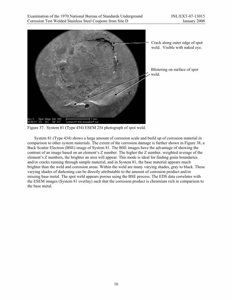
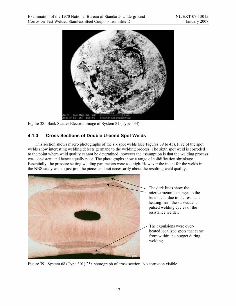
System 81 (Type 434) shows a large amount of corrosion scale and build up of corrosion material in comparison to other system materials. The extent of the corrosion damage is further shown in Figure 38, a Back Scatter Electron (BSE) image of System 81. The BSE images have the advantage of showing the contrast of an image based on an element’s Z number. The higher the Z number, weighted average of the element’s Z numbers, the brighter an area will appear. This mode is ideal for finding grain boundaries and/or cracks running through sample material, and in System 81, the base material appears much brighter than the weld and corrosion areas. Within the weld are many varying shades, gray to black. These varying shades of darkening can be directly attributable to the amount of corrosion product and/or missing base metal. The spot weld appears porous using the BSE process. The EDS data correlates with the ESEM images (System 81 overlay) such that the corrosion product is chromium rich in comparison to the base metal.
Crack along outer edge of spot weld. Visible with naked eye.
Blistering on surface of spot weld.
Examination of the 1970 National Bureau of Standards Underground INL/EXT-07-13015 Corrosion Test Welded Stainless Steel Coupons from Site D January 2008
17
Figure 38. Back Scatter Electron image of System 81 (Type 434).
4.1.3 Cross Sections of Double U-bend Spot Welds
This section shows macro photographs of the six spot welds (see Figures 39 to 45). Five of the spot welds show interesting welding defects germane to the welding process. The sixth spot weld is corroded to the point where weld quality cannot be determined; however the assumption is that the welding process was consistent and hence equally poor. The photographs show a range of solidification shrinkage. Essentially, the pressure setting welding parameters were too high. However the intent for the welds in the NBS study was to just join the pieces and not necessarily about the resulting weld quality.
Figure 39. System 68 (Type 301) 25X photograph of cross section. No corrosion visible.
The expulsions were over-heated localized spots that came from within the nugget during welding.
The dark lines show the microstructural changes to the base metal due to the resistant heating from the subsequent pulsed welding cycles of the resistance welder.

Examination of the 1970 National Bureau of Standards Underground INL/EXT-07-13015 Corrosion Test Welded Stainless Steel Coupons from Site D January 2008
18
Figure 40. System 68 (Type 301) 100X photograph of expulsion.
Figure 41. System 71 (Type 301) 25X photograph of cross section with large shrinkage void. No corrosion visible.
The expulsions erupted out from the base metal, re-solidified on the surface, and were flattened by the resistance welding electrodes while the metal was still hot. The expulsions were given a spectrographical analysis and the copper values were higher due to the contact with the copper electrodes during welding.

Examination of the 1970 National Bureau of Standards Underground INL/EXT-07-13015 Corrosion Test Welded Stainless Steel Coupons from Site D January 2008
19
Figure 42. System 73 (Type 304) 25X photograph of cross section with small shrinkage voids. No corrosion visible.
Figure 43. System 75 (Type 304) 25X photograph of cross section with small shrinkage voids. No corrosion visible.
Examination of the 1970 National Bureau of Standards Underground INL/EXT-07-13015 Corrosion Test Welded Stainless Steel Coupons from Site D January 2008
20
Figure 44. System 78 (Type 316) 25X photograph of cross section with large shrinkage voids. No corrosion visible.
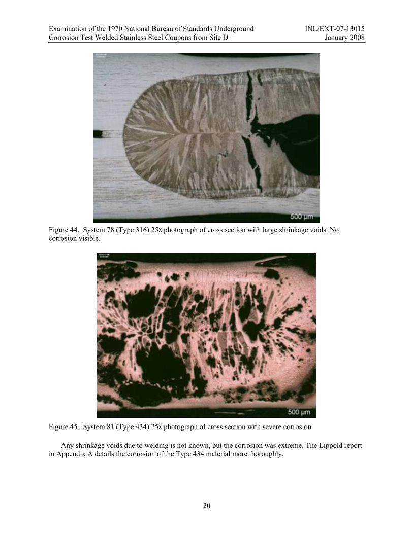
Figure 45. System 81 (Type 434) 25X photograph of cross section with severe corrosion.
Any shrinkage voids due to welding is not known, but the corrosion was extreme. The Lippold report in Appendix A details the corrosion of the Type 434 material more thoroughly.

Examination of the 1970 National Bureau of Standards Underground INL/EXT-07-13015 Corrosion Test Welded Stainless Steel Coupons from Site D January 2008
21
4.2 Corrosion on Cross Bead Plate Coupons The two cross-bead plate coupons were essentially identical in outward appearance. (See Figures 15-
18.) The surfaces had no general corrosion, just slight rust staining, but they looked remarkable for being buried for over 33 years. There was, however, several small pits found both at the edge near the end of the welds and on the edge surface of the plate of sample 54D20 (see Figure 46 and 47). Pits were also found on sample 54D19.
Figure 46. Close-up top view of end of weld at edge of plate on sample 54D20.
Figure 47. Close-up end view of plate at the beginning point of weld on sample 54D20.
End of weld on plate. Weld is about 0.23-in wide.
Pits. These pits were near the weld at the edge of the plate or on the edge surface.
Starting point of weld on plate.
Pits and tunneling corrosion into the edge surface of the plate.
NOTE: The actual width of the section shown in this photograph is 0.44-in wide.
Edge surface of plate.
Top surface of plate.
Superficial surface corrosion equally spaced on both sides of the weld and is about 0.12 in from the weld. Typical on both plates.

Examination of the 1970 National Bureau of Standards Underground INL/EXT-07-13015 Corrosion Test Welded Stainless Steel Coupons from Site D January 2008
22
The following sketch, Figure 48, shows the locations on the plates where sections of both cross bead plates were removed for metallurgical analysis. These were also the locations of the pitting on the plates as illustrated in the metallographic cross sections of the welds, Figures 49-51.
Figure 48. Locations on plates where pits were located and where sections were removed.
Figure 49. End view of cross sectioned weld about 1-in from the edge of the plate, sample 54D19.
The plate is 0.06-in thick and the weld is about 0.2-in wide. (Lippold et al., 2007).

Examination of the 1970 National Bureau of Standards Underground INL/EXT-07-13015 Corrosion Test Welded Stainless Steel Coupons from Site D January 2008
23
Figure 50. Tunneling corrosion in the weld metal.
Figure 51. Tunneling corrosion was into the base metal.
The corrosion in these plates is identical to what was reported by the NBS in 1981 (Gerhold et al., 1981). In 1981, they reported the plates had pitting and tunneling along and adjacent to the weld and at the plate edge. In an informal discussion with Edward Escalante, one of the former NBS researchers, he stated that he believed that the tunneling corrosion may be accentuated by gravity. The plates were buried into the trenches with the long direction of the plate vertical. The tunneling observed in the cross-section sampled from the top and bottom edges of the welded plate was directed in the long direction of the plate along the weld. The cause of the tunneling corrosion will be further investigated in examinations of the non-welded samples.
The penetration was completely through the plate at the edge of plate.
Weld is smaller in width because it was at the beginning of the weld. Cross section was about 0.5 in from the edge of plate (Lippold et al., 2007).
Tunneling corrosion was preferential into the weld metal (Lippold et al., 2007).
Tunneling corrosion was into the base metal.

Examination of the 1970 National Bureau of Standards Underground INL/EXT-07-13015 Corrosion Test Welded Stainless Steel Coupons from Site D January 2008
24
4.3 Corrosion on Welded Tube Coupons There were six welded tubes examined:
Two 2.0-in OD GTAW seam welded Type 304 tubes, System 57 Two 1.25-in OD GTAW seam welded Type 409 tubes, System 62 Two 0.875-in OD high frequency induction seam welded Type 409 tubes, System 63
4.3.1 System 57, Type 304 Tubes
The two tubes were essential identical with no observable general or surface corrosion. Upon examination, the surface showed an etched condition. The etched condition concurred with the results of the NBS report. The welded tubes, samples 57D19 and 57D20, were given a total anneal according to the specifications in ASTM A249. The welds were performed by GTAW, and upon examination, the tubes showed no internal/external general corrosion or attack. Aside from a few isolated surface localized pits under the rubber stopper, there was no obvious corrosion after 33 years. Figure 52 shows the lack of corrosion on sample 57D19 upon removal.
Figure 52. System 57, Type 304 GTAW welded coupon with removed rubber stopper.
Examination of the 1970 National Bureau of Standards Underground INL/EXT-07-13015 Corrosion Test Welded Stainless Steel Coupons from Site D January 2008
25
4.3.1.1 System 57, Collages
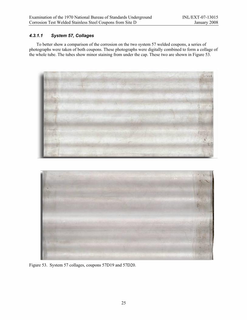
To better show a comparison of the corrosion on the two system 57 welded coupons, a series of photographs were taken of both coupons. These photographs were digitally combined to form a collage of the whole tube. The tubes show minor staining from under the cap. These two are shown in Figure 53.
Figure 53. System 57 collages, coupons 57D19 and 57D20.
Examination of the 1970 National Bureau of Standards Underground INL/EXT-07-13015 Corrosion Test Welded Stainless Steel Coupons from Site D January 2008
26
4.3.2 System 62, Type 409 Tubes
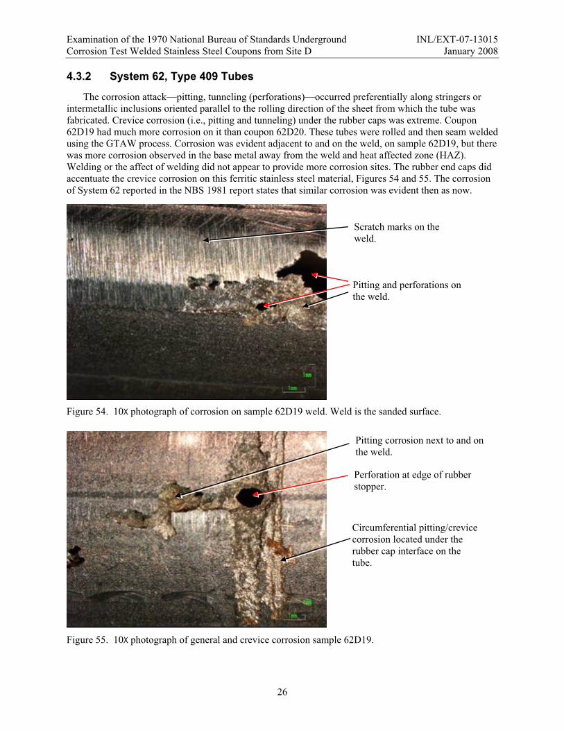
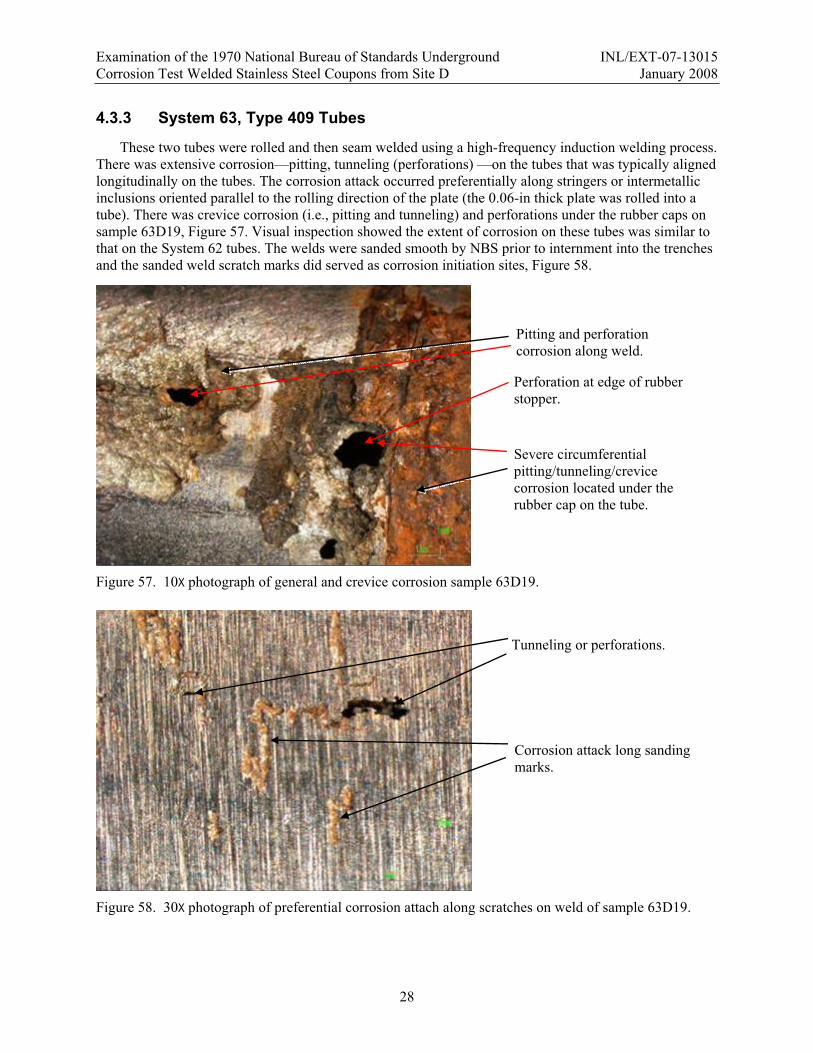
The corrosion attack—pitting, tunneling (perforations)—occurred preferentially along stringers or intermetallic inclusions oriented parallel to the rolling direction of the sheet from which the tube was fabricated. Crevice corrosion (i.e., pitting and tunneling) under the rubber caps was extreme. Coupon 62D19 had much more corrosion on it than coupon 62D20. These tubes were rolled and then seam welded using the GTAW process. Corrosion was evident adjacent to and on the weld, on sample 62D19, but there was more corrosion observed in the base metal away from the weld and heat affected zone (HAZ). Welding or the affect of welding did not appear to provide more corrosion sites. The rubber end caps did accentuate the crevice corrosion on this ferritic stainless steel material, Figures 54 and 55. The corrosion of System 62 reported in the NBS 1981 report states that similar corrosion was evident then as now.
Figure 54. 10X photograph of corrosion on sample 62D19 weld. Weld is the sanded surface.
Figure 55. 10X photograph of general and crevice corrosion sample 62D19.
Scratch marks on the weld.
Pitting and perforations on the weld.
Pitting corrosion next to and on the weld.
Perforation at edge of rubber stopper.
Circumferential pitting/crevice corrosion located under the rubber cap interface on the tube.

Examination of the 1970 National Bureau of Standards Underground INL/EXT-07-13015 Corrosion Test Welded Stainless Steel Coupons from Site D January 2008
27
4.3.2.1 System 62, Collages
To better show a comparison between the two system 62 welded coupons, a series of photographs were taken of both coupons (see figure 56). These photographs were digitally matched/linked together into a collage of the whole tube. The corrosion under the caps was extreme with many perforations, and sample 62D19 also had numerous linear corrosion areas and multiple perforations.
Figure 56. System 62 collages, coupons 62D19 and 62D20.
Examination of the 1970 National Bureau of Standards Underground INL/EXT-07-13015 Corrosion Test Welded Stainless Steel Coupons from Site D January 2008
28
4.3.3 System 63, Type 409 Tubes
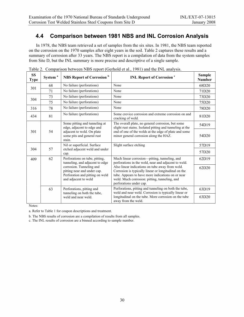
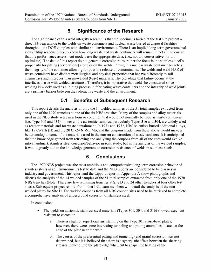
These two tubes were rolled and then seam welded using a high-frequency induction welding process. There was extensive corrosion—pitting, tunneling (perforations) —on the tubes that was typically aligned longitudinally on the tubes. The corrosion attack occurred preferentially along stringers or intermetallic inclusions oriented parallel to the rolling direction of the plate (the 0.06-in thick plate was rolled into a tube). There was crevice corrosion (i.e., pitting and tunneling) and perforations under the rubber caps on sample 63D19, Figure 57. Visual inspection showed the extent of corrosion on these tubes was similar to that on the System 62 tubes. The welds were sanded smooth by NBS prior to internment into the trenches and the sanded weld scratch marks did served as corrosion initiation sites, Figure 58.
Figure 57. 10X photograph of general and crevice corrosion sample 63D19.
Figure 58. 30X photograph of preferential corrosion attach along scratches on weld of sample 63D19.
Tunneling or perforations.
Corrosion attack long sanding marks.
Pitting and perforation corrosion along weld.
Perforation at edge of rubber stopper.
Severe circumferential pitting/tunneling/crevice corrosion located under the rubber cap on the tube.

Examination of the 1970 National Bureau of Standards Underground INL/EXT-07-13015 Corrosion Test Welded Stainless Steel Coupons from Site D January 2008
29
4.3.3.1 System 63, Collages
To better show a comparison between the two system 63 welded coupons, a series of photographs were taken of both coupons (see figure 59). These photographs were digitally matched/linked together into a collage of the whole tube. The corrosion under the caps was more extreme on coupon 63D19 than the other coupon. Also there was more corrosion on and near the weld on 63D19 than on 63D20. Both coupons had numerous linear corrosion areas and with multiple perforations.
Figure 59. System 63 collages, coupons 63D19 and 63D20.
Examination of the 1970 National Bureau of Standards Underground INL/EXT-07-13015 Corrosion Test Welded Stainless Steel Coupons from Site D January 2008
30
4.4 Comparison between 1981 NBS and INL Corrosion Analysis In 1978, the NBS team retrieved a set of samples from the six sites. In 1981, the NBS team reported
on the corrosion on the 1970 samples after eight years in the soil. Table 2 captures these results and a summary of corrosion after 33 years. The NBS report is a compilation of data from the system samples from Site D, but the INL summary is more precise and descriptive of a single sample.
Table 2. Comparison between NBS report (Gerhold et al., 1981) and the INL analysis. SS
Type System a NBS Report of Corrosion b INL Report of Corrosion c Sample Number
68 No failure (perforations) None 68D20 301
71 No failure (perforations) None 71D20 73 No failure (perforations) None 73D20
304 75 No failure (perforations) None 75D20
316 78 No failure (perforations) None 78D20
434 81 No failure (perforations) Some crevice corrosion and extreme corrosion on and cracking of weld. 81D20
54D19
301 54
Some pitting and tunneling at edge, adjacent to edge and adjacent to weld. On plate some pits and general rust stain.
The overall plate, no general corrosion, but some slight rust stains. Isolated pitting and tunneling at the end of one of the welds at the edge of plate and some minor general corrosion along the HAZ. 54D20
57D19 304 57
Nil or superficial. Surface etched adjacent weld and under cap.
Slight surface etching
57D20
62D19 62 Perforations on tube, pitting, tunneling, and adjacent to edge corrosion. Tunneling and pitting near and under cap. Perforation and pitting on weld and adjacent to weld
Much linear corrosion—pitting, tunneling, and perforations in the weld, near and adjacent to weld. Also linear indications on tube away from weld. Corrosion is typically linear or longitudinal on the tube. Appears to have more indications on or near weld. Much corrosion: pitting, tunneling, and perforations under cap.
62D20
63D19
409
63 Perforations, pitting and tunneling on both the tube, weld and near weld.
Perforations, pitting and tunneling on both the tube, weld and near weld. Corrosion is typically linear or longitudinal on the tube. More corrosion on the tube away from the weld.
63D20
Notes:a. Refer to Table 1 for coupon descriptions and treatment. b. The NBS results of corrosion are a compilation of results from all samples. c. The INL results of corrosion are a binned according to sample number.
Examination of the 1970 National Bureau of Standards Underground INL/EXT-07-13015 Corrosion Test Welded Stainless Steel Coupons from Site D January 2008
31
5. Significance of the Research The significance of this weld integrity research is that the specimens buried at the test site present a
direct 33-year analog to the welds on waste containers and nuclear waste buried at disposal facilities throughout the DOE complex with similar soil environments. There is an implied long-term governmental stewardship responsibility to know how long waste and waste containers will remain intact and to ensure that the performance assessment models use the appropriate data, (i.e., not too conservative nor too optimistic). The data of this report do not generate corrosion rates, rather the focus is the stainless steel’s propensity for pitting (perforations) along or on the welds. Pitting in a nuclear waste container breaches the integrity of the container allowing for possible release of contaminants. The welds and weld HAZ of waste containers have distinct metallurgical and physical properties that behave differently to soil chemistries and microbes than un-welded (base) materials. The old adage that failure occurs at the interfaces is true with welded structures. Therefore, it is imperative that welds be considered since welding is widely used as a joining process in fabricating waste containers and the integrity of weld joints are a primary barrier between the radioactive waste and the environment.
5.1 Benefits of Subsequent Research This report details the analysis of only the 14 welded samples of the 51 total samples extracted from
only one of the 1970 trenches at one of the six NBS test sites. Many of the samples and alloy materials used in the NBS study were in a form or condition that would not normally be used as waste containers (i.e. Type 409 and 434); however, the austenitic samples, particularly Types 316 and 304, are widely used as reactor materials and for waste containment. In 1971 and 1972, NBS scientists buried additional alloys, like 18 Cr-8Ni (N) and the 20 Cr-24 Ni-6.5 Mo, and the coupons made from these alloys would make a better analog to some of the materials used in the current construction of waste canisters. It is anticipated that the knowledge gained from retrieving and analyzing the coupons from all of the sites would evolve into a landmark stainless steel corrosion/behavior in soils study, but in the analysis of the welded samples, it would greatly add to the knowledge germane to corrosion resistance of welds in stainless steels.
6. Conclusions The 1970 NBS project was the most ambitious and comprehensive long-term corrosion behavior of
stainless steels in soil environments test to date and the NBS reports are considered to be classics in industry and government. This report and the Lippold report in Appendix A show photographs and discuss the analysis of the 14 welded samples of the 51 total samples extracted from only one of the 1970 NBS trenches (Note: There are five remaining trenches at Site D and 24 other trenches at four other test sites.). Subsequent project reports from other INL team members will detail the analysis of the non-welded plates for Site D. The welded coupons from all NBS coupon sites need to be retrieved to complete a comprehensive analysis of underground corrosion of stainless steel.
In conclusion:
The welds on austenitic stainless steel materials (Types 301, 304, and 316) showed excellent resistant to corrosion.
a. There is slight or superficial rust staining on the Type 301 cross-bead plates; however, there were some interesting tunneling and pitting anomalies located at the edge of the plate near the weld.
b. The causes of the preferential pitting and tunneling (end grain) corrosion was not determined, but it is believed that there is a synergistic affect between the shearing stresses induced into the plate edge when cut to shape, the heating of the

Examination of the 1970 National Bureau of Standards Underground INL/EXT-07-13015 Corrosion Test Welded Stainless Steel Coupons from Site D January 2008
32
microstructure and base metal during welding, and the intermetallic strings or inclusions related to the rolling during plate manufacturing.
c. The weld and HAZ of the seam-welded Type 304 tubes showed no corrosion. Aside from some minor surface localized pits, no crevice corrosion was present under the rubber caps on the tubes. The overall surface was etched, but no visible general corrosion attack on either external or internal surfaces were present.
d. The (Types 301, 304, and 316) resistance spot-welded U-bends showed no corrosion on the stressed surface or in the crevice between the two sheets.
The welds on ferritic stainless steel materials (Types 409 and 434) showed varied resistant to corrosion.
a. The Type 434 U-bend sample was heavily attacked. This attack occurred in both the weld nugget and HAZ and appeared to initiate at the ferrite/martensite interface at the ferrite grain boundaries. It is not known how much improper welding affected the gross corrosion attack.
b. The 0.875-in diameter high-frequency induction-welded seams on the Type 409 (system 63) tubes were severely attacked. The attack (pitting and perforations) was associated with both the weld and the base metal and was influenced by the forming (rolling) direction of the tube. Extreme crevice corrosion attack was evident under the rubber tube cap. One of the coupons examined, 63D19, had several corrosion areas on and adjacent to the weld, but there were equally corroded areas away from the weld. Some corrosion was initiated on the sanding marks on the weld and may not have been related to the affect of the welds.
c. The GTAW-welded seams on one of the 1.25-in diameter Type 409 (system 62) tubes were more severely attacked than the other. The corrosion on these larger tubes was similar to intensity to the corrosion on the smaller system 63 tubes. The attack (pitting and perforations) was associated with both the weld and the base metal and appeared to be influenced by the forming direction of the tube. The sanding of the weld may have resulted in some of the attack on the weld. Evidence showed that corrosion attacked the sanding scratches. Extreme crevice corrosion attack with through the tube penetrations was evident under the rubber tube cap.
d. The analysis of the corrosion attack of these ferritic stainless steel materials was academic and interesting to look at, but these alloys would never be selected for long-term underground corrosion resistant applications of interest to nuclear waste disposal.
The metallography of the U-bend welds showed that all of the welds were defective (i.e., the welding process caused extreme weld nugget shrinkage), but poor welding was not an analysis issue or concern.

Examination of the 1970 National Bureau of Standards Underground INL/EXT-07-13015 Corrosion Test Welded Stainless Steel Coupons from Site D January 2008
33
7. References
Gerhold, W.F., E. Escalante, and B.T. Sanderson. “The Corrosion Behavior of Selected Stainless Steels in Soil Environments.” NBSIR 81-2228, February 1981.
Lippold, L.C., J.W. Sowards, and L.R. Zirker. “Final Report: Corrosion Behavior of Welded Stainless Steels in Soil Environments.” Ohio State University Welding engineering Program and Idaho National Laboratory. June 26, 2007.

Examination of the 1970 National Bureau of Standards Underground INL/EXT-07-13015 Corrosion Test Welded Stainless Steel Coupons from Site D January 2008
Examination of the 1970 National Bureau of Standards Underground INL/EXT-07-13015 Corrosion Test Welded Stainless Steel Coupons from Site D January 2008
Appendix A
Final Report: Corrosion Behavior of Welded Stainless Steels in Soil Environments
J.C. Lippold and J.W. Sowards Welding Engineering Program
The Ohio State University Columbus, OH
and
L. Zirker Idaho National Laboratory
Idaho Falls, ID
June 26, 2007
This investigation was supported by the Environmental Management Science Program of the Office of Science, U.S. Department of Energy.
Examination of the 1970 National Bureau of Standards Underground INL/EXT-07-13015 Corrosion Test Welded Stainless Steel Coupons from Site D January 2008
CONTENTS of APPENDIX A
A.1. Abstract………………………………………………………………………………... A-1 A.2 Introduction…………………………………………………………………………… A-1 A.3 Materials and Investigative Procedures……………………………………………….. A-2 A.4 Results…………………………………………………………………………….…… A-3 A.5 Discussion…………………………………………………………………………….. A-7 A.6 Conclusions…………………………………………………………………………… A-8
TABLES in APPENDIX A
A.1 Chemical Composition of Stainless Steels……………………………………………. A-2 A.2 Sample Identification and Condition…………………………………………..…….... A-3 A.3 Summary of Visual Examination……………………………………………………… A-4
FIGURES in APPENDIX A
A.1 Double U-bend samples……………………………….………………….…………. A-9 A.2 HFI welded in Type 409 tube, Sample 63D20…………………………....…………. A-10 A.3 GTA welded Type 409 tube, Sample 62D19……………………………...………… A-11 A.4 Cross sections of the Type 304 double U-bend resistance spot welds………………. A-12 A.5 Cross section of a Type 301 double U-bend resistance spot weld, Sample 68D20….... A-13 A.6 Cross section of resistance spot weld in Type 434, Sample 81D20……………….... A-14 A.7 Cross sections of welds from Type 301 cross welded plate…………………………. A-15 A.8 Cross section through the weld stop region at the edge of the plate, Sample 54D20…. A-16 A.9 Cross section of longitudinal seam weld in Type 304 tube, Sample 57D19……….... A-17 A.10 Cross sections of seam welds in Type 409 tubes…………………………………..... A-18
ACRONYMS AISI American Institute of Steel and Iron EDS Energy Dispersive Spectrometer FN Ferrite Number GTA Gas Tungsten Arc (weld) HAZ Heat Affected Zone HFI High Frequency Induction (weld) INL Idaho National Laboratory MIC Microbially l Induced Corrosion NIST National Institute of Standards and Technology RSW Resistance Spot (weld) SEM Scanning Electron Microscope

Examination of the 1970 National Bureau of Standards Underground INL/EXT-07-13015 Corrosion Test Welded Stainless Steel Coupons from Site D January 2008
A-1
A.1 ABSTRACT
Welded samples from a National Institute of Standards and Testing (NIST) and American Iron and Steel Institute (AISI) study to evaluate the corrosion behavior of various stainless steels to long term burial in different soil conditions were analyzed in this study. The samples in this study were removed from a site in Wildwood, New Jersey after 34 years of burial. The samples included resistance spot welded U-bends in Type 301, 304, 316, and 434 alloys, gas tungsten arc cross welds made on Type 301 plate, and seam welded Type 304 and 409 tubes.
In general, the 300-series austenitic stainless steels (Types 301, 304, and 316) were very resistant to corrosion in all the conditions examined. The Type 434 U-bend samples exhibited both crevice corrosion and attack of the weld nugget and heat affected zone. This attack occurred preferentially at the ferrite/martensite interface along the ferrite grain boundaries.
Type 409 seam welded tubes made by both the gas tungsten arc and high frequency induction welding processes exhibited severe corrosion attack. This attack occurred both in the welds and the base metal. The severe attack in these samples is undoubtedly due to the low chromium content of this alloy (~11 wt%) rather than any effect of the welding process.
Based on this investigation, austenitic stainless steels exhibit the best corrosion resistance in the particular soil environment that was studied. The effect of base metal processing (annealed or cold worked) was negligible as determined from the U-bend sample results.
A.2 INTRODUCTION
The National Institute of Standards and Testing (NIST) has been actively involved in underground corrosion studies since the early 1900’s when it was authorized by congress to study the corrosion of underground pipelines. In the early 1970s, an extensive program sponsored by the American Iron and Steel Institute (AISI) was commissioned to study the corrosion of various stainless steel alloys in different soil environments. Under this program, thousands of stainless steel samples in various forms and conditions were buried at six test sites in the United States. The test sites were selected based on soil characteristics, ranging from a tidal marsh to sandy loam, and coastal sand.
The buried samples included martensitic, ferritic, and austenitic stainless steel alloys in sheet and tube form in the annealed, cold worked, and sensitized conditions. Welded samples were also buried and included welded tubes and sheets, and U-bend configurations.
The initial NIST study called for removal and inspection of samples after 1, 2, 4, and 8 years and provided for one set to be removed at an unspecified time in the future. The samples examined in this study were excavated in 2006 from a site at the Coast Guard Station in Wildwood, New Jersey after approximately 34 years of burial. The soil at this site is classified as a “white, loose sand with some black streaks in places and supports an abundant growth of beach grasses.” At the time of burial, the soil pH was 5.7 and the resistivity 13,800-57,500 ohm-cm.a
a W.F. Gerhold, E. Escalante, and B.T. Sanderson. The Corrosion Behavior of Selected Stainless Steels in Soil Environments. NBSIR 81-2228, February 1981.

Examination of the 1970 National Bureau of Standards Underground INL/EXT-07-13015 Corrosion Test Welded Stainless Steel Coupons from Site D January 2008
A-2
A.3 MATERIALS AND INVESTIGATIVE PROCEDURES
A.3.1 Materials
The samples investigated in this study consisted of three austenitic stainless steels – Types 301, 304, and 316, and two ferritic stainless steels – Types 409 and 434. The composition of these materials is provided in Table A.1. The sample numbers, and material and welding conditions are summarized in Table A.2.
A.3.2 Investigative Procedures
Samples were inspected visually under a binocular microscope at magnifications up to 80X. Based on this inspection, locations for sample sectioning and metallographic analysis were determined. Digital photos were taken of the samples prior to sectioning.
Samples for metallographic analysis were mounted in bakelite and progressively ground and polished. The final polishing used 0.05-micron colloidal silica with a vibratory polisher. Etching was performed electrolytically using a 10% oxalic acid solution. Etching conditions were 3.0 volts for 30-90 seconds. Following etching, photomicrographs were taken at magnifications ranging from 25 to 400X.
For the austenitic stainless steel cross and seam welds, the MagneGage was used to measure the ferrite content in the weld metal. The ferrite content is reported as Ferrite Number (FN), where FN is roughly equivalent to volume percent ferrite at values below FN 8.
Table A.1 Chemical Composition of Stainless Steels (from Ref. 1)Composition (wt%) SS
Type System
ID*Cr Ni Mn Si Mo C N Cu S P Other
54 16.1 7.1 1.1 0.49 NR 0.092 NR NR 0.006 0.015 0.09Co
68 17.43 7.14 1.02 0.34 0.22 0.10 NR NR 0.016 0.030 301
71 16.98 7.23 0.86 0.54 NR 0.13 NR NR 0.013 0.020
55,56, 73 18.2 9.8 1.46 0.50 0.17 0.048 0.042 0.19 0.012 0.030
57 18.45 9.11 0.82 0.68 0.40 0.06 NR 0.25 0.015 0.024 304
75 17.6 9.8 1.0 0.64 0.15 0.051 0.16 0.11 0.009 0.022
316 58,59 17.48 13.53 1.62 0.53 2.28 0.049 NR 0.11 0.009 0.020
62 11.22 0.67 0.51 0.44 NR 0.05 NR NR 0.013 0.024 0.65Ti 409
63 11.20 0.34 0.41 0.44 NR 0.05 NR NR 0.018 0.022 0.55Ti
434 81 18.20 0.32 0.42 0.43 0.76 0.076 0.046 0.05 0.011 0.017 0.046Al 0.025V
* System ID from NBS report (Ref. 1), NR = not reported
Examination of the 1970 National Bureau of Standards Underground INL/EXT-07-13015 Corrosion Test Welded Stainless Steel Coupons from Site D January 2008
A-3
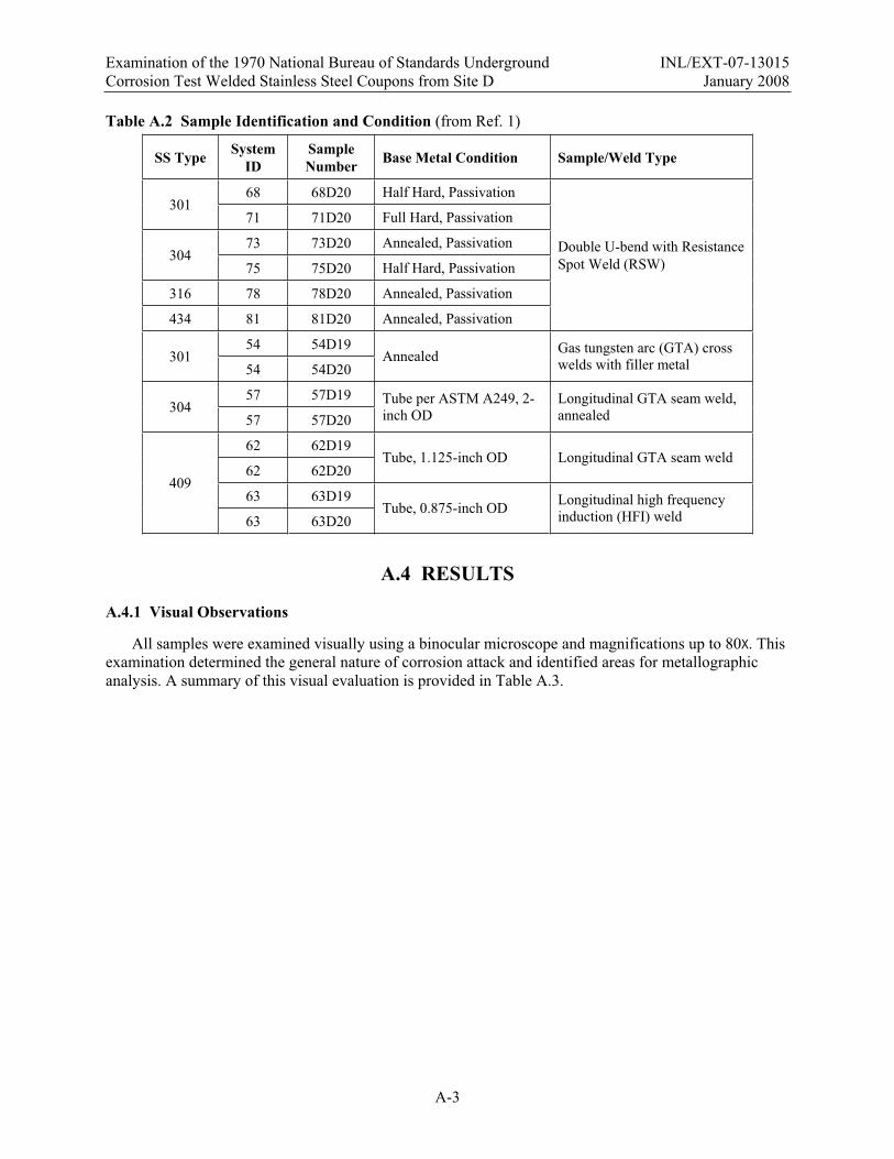
Table A.2 Sample Identification and Condition (from Ref. 1)
SS Type System ID
Sample Number Base Metal Condition Sample/Weld Type
68 68D20 Half Hard, Passivation 301
71 71D20 Full Hard, Passivation
73 73D20 Annealed, Passivation 304
75 75D20 Half Hard, Passivation
316 78 78D20 Annealed, Passivation
434 81 81D20 Annealed, Passivation
Double U-bend with Resistance Spot Weld (RSW)
54 54D19 301
54 54D20 Annealed Gas tungsten arc (GTA) cross
welds with filler metal
57 57D19 304
57 57D20 Tube per ASTM A249, 2-inch OD
Longitudinal GTA seam weld, annealed
62 62D19
62 62D20 Tube, 1.125-inch OD Longitudinal GTA seam weld
63 63D19 409
63 63D20 Tube, 0.875-inch OD Longitudinal high frequency
induction (HFI) weld
A.4 RESULTS
A.4.1 Visual Observations
All samples were examined visually using a binocular microscope and magnifications up to 80X. This examination determined the general nature of corrosion attack and identified areas for metallographic analysis. A summary of this visual evaluation is provided in Table A.3.

Examination of the 1970 National Bureau of Standards Underground INL/EXT-07-13015 Corrosion Test Welded Stainless Steel Coupons from Site D January 2008
A-4
Table A.3 Summary of Visual Examination
SS Type System ID
Sample Number Base Metal Condition Sample/Weld Type
68 68D20 No apparent corrosion 301
71 71D20 No apparent corrosion
73 73D20 No apparent corrosion 304
75 75D20 No apparent corrosion
316 78 78D20 No apparent corrosion
434 81 81D20 Some attack of weld and crevice corrosion between sheets.
Double U-bend with RSW
54 54D19 301
54 54D20
Pitting corrosion at weld stop near edge of plate. Some minor general corrosion in HAZ.
GTA cross welds with filler metal
57 57D19 304
57 57D20 No apparent corrosion Longitudinal GTA
seam weld, annealed
62 62D19
62 62D20
Some corrosion attack in base metal and weld. Corrosion perforated through the tube wall. Crevice corrosion at tube ends
Longitudinal GTA seam weld
63 63D19 409
63 63D20
Severe corrosion attack along weld and in base metal. Multiple perforations in tube wall. Crevice corrosion at tube ends.
Longitudinal HFI weld
A.4.1.1 Double U-bend Samples with Resistance Spot Welds (Types 301, 304, 316 and 434)
Photos of representative double U-bend samples are shown in Figure A.1. These samples consisted of sheet samples of dimensions 12 in. 1 in. 0.06 in. welded using the resistance spot welding (RSW) process. Visual examination of the Type 301, 304, and 316 spot welded samples revealed virtually no evidence of corrosion. There was obvious corrosion of the Type 434 sample. The weld itself was attacked and there was considerable crevice corrosion between the two sheets (see bottom photo in Figure A.1).
All the double U-bend samples also showed evidence of expulsions on the surface, presumably resulting from “spitting” of the RSW electrode during welding. A summary of the visual observations is provided in Table A.3.
A.4.1.2 Type 301 Cross Weld - GTAW
The Type 301 cross welded samples (two were examined) showed virtually no evidence of corrosion or surface staining. Under higher magnification examination (30X) using a binocular microscope, some evidence of superficial attack was observed in the heat affected zone (HAZ) of these welds. Some attack was observed on the edge of the plate near the terminal crater (stop area) of one weld.

Examination of the 1970 National Bureau of Standards Underground INL/EXT-07-13015 Corrosion Test Welded Stainless Steel Coupons from Site D January 2008
A-5
A.4.1.3 Welded Tube - Longitudinal Seam Welds (Type 304 and 409)
The Type 304 longitudinal seam welds were made using the Gas Tungsten Arc (GTA) weld process and annealed following welding according to ASTM A249b. There was no corrosion attack associated with this weld.
The Type 409 seam weld samples were in various tube diameters and were made with both the high frequency induction (HFI) welding process and the GTAW process. All of these samples exhibited severe corrosion attack. This attack was associated with the welds and regions remote from the welds. There was also significant crevice corrosion at the ends of the sample where the end caps had been in place. In general, corrosion of the HFI welds appeared worse than the GTA welds, although severe corrosion was present in both types.
Photos of a representative HFI weld are shown in Figure A.2. There was a second sample that showed similar corrosion attack. Crevice corrosion was observed at both ends of the tube. The inset photo shows corrosion associated with the weld and regions of the tube well away from the weld. The directional nature of the corrosion in the base metal is along the rolling direction of the sheet used to make the tube.
Photos of a representative GTA weld in Type 409 are shown in Figure A.3. There were also two of these samples that were examined. Again, crevice corrosion is evident at the tube ends. Corrosion along the length of the tube is shown in the exploded view on the right. Note that this corrosion is not associated with the weld.
A.4.2 Metallographic Analysis
Based on visual examination under the binocular microscope, regions of the welded samples were selected for metallographic examination. Samples were polished and etched to reveal the weld microstructure and provide microstructural information regarding any corrosion attack.
A.4.2.1 Double U-bend Samples with Resistance Spot Welds
Cross sections of the resistance spot welds in Type 304, systems 73 and 75 are shown in Figure A.4. The system 73 weld contains a small amount of delta ferrite (FN 2) and exhibits a solidification shrinkage pore in the center of the weld. The system 75 weld was fully austenitic (FN 0) and exhibited multiple solidification cracks. There was essentially no corrosion attack on the surface of these welds when examined in cross section.
A cross section of the Type 301, system 68 weld is shown in Figure A.5. This weld contained a small amount of ferrite (FN 1-2) and also exhibited a large solidification shrinkage void at the center of the weld. Some superficial surface cracking was observed in this cross section, as shown in the bottom photo of Figure A.5. It appears that this cracking was associated with the surface copper contamination that was observed visually. This copper contamination had been previously identified at Idaho National Laboratory using scanning electron microscopy. The cracking associated with this copper does not appear to be the result of corrosion during ground exposure.
Corrosion attack in the Type 434 double U-bend sample was much more severe than in the 300-series alloys. A cross section of the Type 434 weld is shown in Figure A.6. Severe corrosion attack occurred in both the weld nugget and the HAZ. In the HAZ (region A in Figure A.6), attack occurred preferentially at
b ASTM A249, Standard Specification for Welded Austenitic Steel Boiler, Superheater, Heat Exchanger, and Condenser Tubes.

Examination of the 1970 National Bureau of Standards Underground INL/EXT-07-13015 Corrosion Test Welded Stainless Steel Coupons from Site D January 2008
A-6
the transition between the base metal and the HAZ. Within the weld nugget, it appears that corrosion attack initiates at the ferrite-martensite interface at the ferrite grain boundaries (region B in Figure A.6).
A.4.2.2 Type 301 Cross Weld - GTAW
Visual examination of the two cross welded samples revealed virtually no corrosion attack. These welds represented a simple bead on plate weld made with an unspecified welding process and filler metal. Based on the bead shape, the welding process was probably gas tungsten arc welding (GTAW). The filler metal was most likely Type 308 (ER308) since the weld deposit was determined to contain ferrite in the range of FN 5-6 (approximately 5-6 volume percent ferrite). A representative cross section of the welds in these plates is shown in the top photo in Figure A.7.
Some corrosion attack was observed at the very edge of the plate. It was not observable on the surface, but could be seen on the edge of the plate. A cross section through a region of this weld approximately 10 mm from the edge is shown in the bottom photo in Figure A.7. Note that the corrosion attack occurs preferentially in the weld metal in this sample.
At the weld stop region in the other cross welded plate, corrosion was also observed on the edge of the plate. When this region was sectioned, the corrosion attack was found to be isolated in the base metal close to the center of the plate, as shown in Figure A.8. This type of corrosion attack is reminiscent of “end grain” corrosion, where attack occurs preferentially along stringers or intermetallic inclusions oriented parallel to the rolling direction of the plate.
A.4.2.3 Welded Tube - Longitudinal Seam Welds (Type 304 and 409)
A cross section of the longitudinal GTA weld in the Type 304 tube (system 57) is shown in the top photo in Figure A.9. This weld was made according to ASTM A249 which specifies that the tube be annealed following welding. This explains why the weld is fully austenitic (no ferrite) even though the tube composition would predict that the ferrite content of the GTA weld would be approximately FN 4.
Under visual examination in the binocular microscope, no apparent corrosion was present. In metallographic cross section, however, some small cracks were observed at grain boundaries, as shown in the bottom photo in Figure A.9. This type of intergranular attack suggests that the grain boundaries may have been sensitized during either welding or upon cooling from the annealing temperature. Note that this attack is extremely superficial, penetrating less than 20 microns (0.002 mm) into the tube.
As shown in Figures A.2 and A.3, corrosion in the Type 409 seam welded tubes was severe. Cross sections from both GTA and HFI welded tubes are shown in Figure A.10. In the GTA cross section, corrosion attack is most severe in the HAZ, while in the HFI weld it occurs across the entire weld region. Corrosion attack was so severe in the Type 409 that no “characteristic” location could be identified. Attack was associated with the welds, HAZs, and base metal.
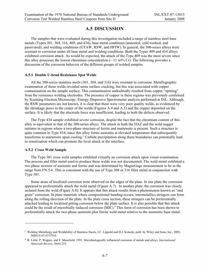
Examination of the 1970 National Bureau of Standards Underground INL/EXT-07-13015 Corrosion Test Welded Stainless Steel Coupons from Site D January 2008
A-7
A.5 DISCUSSION
The samples that were evaluated during this investigation included a range of stainless steel base metals (Types 301, 304, 316, 409, and 434), base metal conditions (annealed, cold worked, and passivated), and welding conditions (GTAW, RSW, and HFIW). In general, the 300-series alloys were resistant to corrosion under all base metal and welding conditions. Both the Types 409 and 434 alloys exhibited corrosion attack. As would be expected, the attack of the Type 409 was the most severe since this alloy possesses the lowest chromium concentration (~ 11 wt% Cr). The following provides a discussion of the corrosion behavior of the different groups of welded samples.
A.5.1 Double U-bend Resistance Spot Welds
All the 300-series stainless steels (301, 304, and 316) were resistant to corrosion. Metallographic examination of these welds revealed some surface cracking, but this was associated with copper contamination on the sample surface. This contamination undoubtedly resulted from copper “spitting” from the resistance welding electrodes. The presence of copper in these regions was previously confirmed by Scanning Electron Microscopy /Energy Dispersive Spectrometer analysis performed at INL. Although, the RSW parameters are not known, it is clear that these were very poor quality welds, as evidenced by the shrinkage pores in the center of the welds (Figures A.4 and A.5) and the copper deposited on the surface. It is likely that the electrode force was insufficient, leading to both the defects observed.
The Type 434 sample exhibited severe corrosion, despite the fact that the chromium content of this alloy is equivalent to that of the 300-series alloys. The attack in both the HAZ and the weld nugget initiates in regions where a two-phase structure of ferrite and martensite is present. Such a structure is quite common in Type 434, since this alloy forms austenite at elevated temperature that subsequently transforms to martensite upon cooling.c Carbide precipitation along these boundaries can potentially lead to sensitization which can promote the local attack at the interface.
A.5.2 Cross Weld Sample
The Type 301 cross weld samples exhibited virtually no corrosion attack upon visual examination. The process and filler metal used to produce these welds was not documented. The weld metal exhibited a two phase mixture of austenite and ferrite and was determined by MagneGage measurement to be in the range from FN 5-6. This is consistent with the use of Type 308 or 316 filler metal in conjunction with Type 301.
Some areas of localized corrosion were observed on the edges of the plate. In one plate the corrosion appeared to preferentially attack the weld metal (Figure A.7). In another plate, the corrosion was clearly isolated from the weld (Figure A.8). It appears that this attack results from a phenomenon known as “end grain” corrosion. In plate materials where compositional banding occurs, intermetallics stringers can form along the rolling direction of the plate. In the plate cross section, these stringers can be preferentially attacked leading to localized pitting corrosion below the plate surface. It is also possible that this attack could be the result of microbially-induced corrosion (MIC).d This form of corrosion has been shown to preferentially attack the two-phase austenite plus ferrite weld metal relative to the austenitic base metal.
c Welding Metallurgy and Weldability of Stainless Steels, J.C. Lippold and D.J. Kotecki, publ. by Wiley and Sons, Inc., 2005, ISBN 0-47147379-0.
d B. Little, P. Wagner, and F. Mansfield. 1991. Microbiologically influenced corrosion of metals and alloys, International Materials Review, 36(6):253.
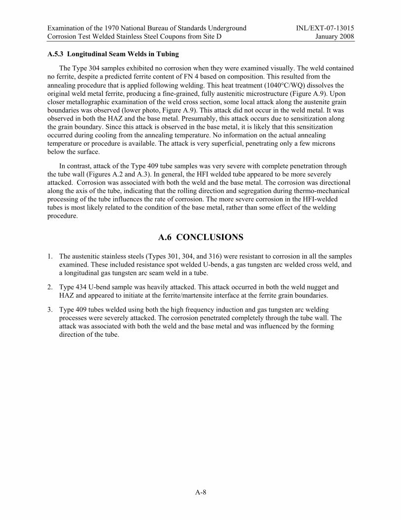
Examination of the 1970 National Bureau of Standards Underground INL/EXT-07-13015 Corrosion Test Welded Stainless Steel Coupons from Site D January 2008
A-8
A.5.3 Longitudinal Seam Welds in Tubing
The Type 304 samples exhibited no corrosion when they were examined visually. The weld contained no ferrite, despite a predicted ferrite content of FN 4 based on composition. This resulted from the annealing procedure that is applied following welding. This heat treatment (1040 C/WQ) dissolves the original weld metal ferrite, producing a fine-grained, fully austenitic microstructure (Figure A.9). Upon closer metallographic examination of the weld cross section, some local attack along the austenite grain boundaries was observed (lower photo, Figure A.9). This attack did not occur in the weld metal. It was observed in both the HAZ and the base metal. Presumably, this attack occurs due to sensitization along the grain boundary. Since this attack is observed in the base metal, it is likely that this sensitization occurred during cooling from the annealing temperature. No information on the actual annealing temperature or procedure is available. The attack is very superficial, penetrating only a few microns below the surface.
In contrast, attack of the Type 409 tube samples was very severe with complete penetration through the tube wall (Figures A.2 and A.3). In general, the HFI welded tube appeared to be more severely attacked. Corrosion was associated with both the weld and the base metal. The corrosion was directional along the axis of the tube, indicating that the rolling direction and segregation during thermo-mechanical processing of the tube influences the rate of corrosion. The more severe corrosion in the HFI-welded tubes is most likely related to the condition of the base metal, rather than some effect of the welding procedure.
A.6 CONCLUSIONS
1. The austenitic stainless steels (Types 301, 304, and 316) were resistant to corrosion in all the samples examined. These included resistance spot welded U-bends, a gas tungsten arc welded cross weld, and a longitudinal gas tungsten arc seam weld in a tube.
2. Type 434 U-bend sample was heavily attacked. This attack occurred in both the weld nugget and HAZ and appeared to initiate at the ferrite/martensite interface at the ferrite grain boundaries.
3. Type 409 tubes welded using both the high frequency induction and gas tungsten arc welding processes were severely attacked. The corrosion penetrated completely through the tube wall. The attack was associated with both the weld and the base metal and was influenced by the forming direction of the tube.
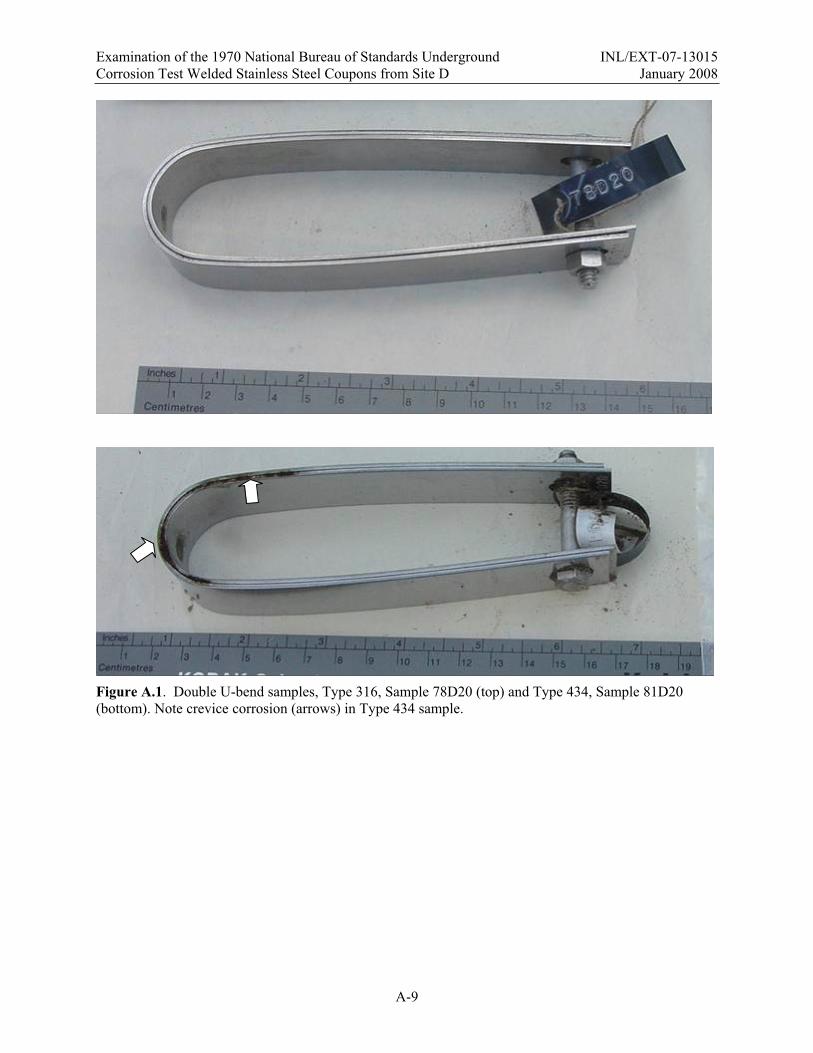
Examination of the 1970 National Bureau of Standards Underground INL/EXT-07-13015 Corrosion Test Welded Stainless Steel Coupons from Site D January 2008
A-9
Figure A.1. Double U-bend samples, Type 316, Sample 78D20 (top) and Type 434, Sample 81D20 (bottom). Note crevice corrosion (arrows) in Type 434 sample.

Examination of the 1970 National Bureau of Standards Underground INL/EXT-07-13015 Corrosion Test Welded Stainless Steel Coupons from Site D January 2008
A-10
Figure A.2. HFI welded in Type 409 tube, Sample 63D20. The boxed area in the upper photo is shown in the lower photo. The arrows indicate the location of the weld along the tube axis. Note crevice corrosion at both ends of the tube.
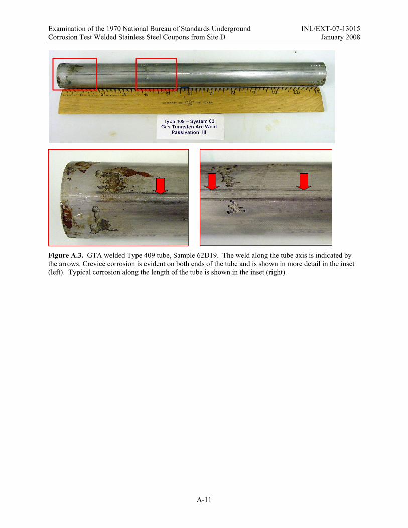
Examination of the 1970 National Bureau of Standards Underground INL/EXT-07-13015 Corrosion Test Welded Stainless Steel Coupons from Site D January 2008
A-11
Figure A.3. GTA welded Type 409 tube, Sample 62D19. The weld along the tube axis is indicated by the arrows. Crevice corrosion is evident on both ends of the tube and is shown in more detail in the inset (left). Typical corrosion along the length of the tube is shown in the inset (right).

Examination of the 1970 National Bureau of Standards Underground INL/EXT-07-13015 Corrosion Test Welded Stainless Steel Coupons from Site D January 2008
A-12
Figure A.4. Cross sections of the Type 304 double U-bend resistance spot welds. Top – Sample 73D20 with FN 2. Bottom – System 75D20 with FN 0 (fully austenitic). Magnification, 25X.

Examination of the 1970 National Bureau of Standards Underground INL/EXT-07-13015 Corrosion Test Welded Stainless Steel Coupons from Site D January 2008
A-13
Figure A.5. Cross section of a Type 301 double U-bend resistance spot weld, Sample 68D20. Top – weld nugget containing a small amount of ferrite (FN 1-2) and center shrinkage cavity. Magnification, 25X. Bottom – some surface cracking (at location indicated by arrow in top photo) possibly associated with copper electrode “spitting” during welding. Magnification, 200X.

Examination of the 1970 National Bureau of Standards Underground INL/EXT-07-13015 Corrosion Test Welded Stainless Steel Coupons from Site D January 2008
A-14
B
A
A B
B
A
B
A
A B
Figure A.6. Cross section of resistance spot weld in Type 434, Sample 81D20 showing extensive corrosion attack. Magnification, 25X. Region A – corrosion attack at interface between the base metal (left) and HAZ. Magnification 100X. Region B – corrosion in the weld nugget appears to occur preferentially at the ferrite-martensite interface. Magnification, 400X.
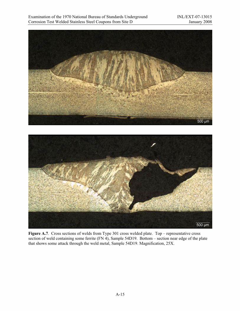
Examination of the 1970 National Bureau of Standards Underground INL/EXT-07-13015 Corrosion Test Welded Stainless Steel Coupons from Site D January 2008
A-15
Figure A.7. Cross sections of welds from Type 301 cross welded plate. Top – representative cross section of weld containing some ferrite (FN 4), Sample 54D19. Bottom – section near edge of the plate that shows some attack through the weld metal, Sample 54D19. Magnification, 25X.

Examination of the 1970 National Bureau of Standards Underground INL/EXT-07-13015 Corrosion Test Welded Stainless Steel Coupons from Site D January 2008
A-16
Figure A.8. Cross section through the weld stop region at the edge of the plate, Sample 54D20. Note that the corrosion is entirely within the base metal. Magnification, 25X.

Examination of the 1970 National Bureau of Standards Underground INL/EXT-07-13015 Corrosion Test Welded Stainless Steel Coupons from Site D January 2008
A-17
Figure A.9. Cross section of longitudinal seam weld in Type 304 tube, Sample 57D19. Top – weld structure is the result of annealing after welding (ASTM A249). Magnification, 25X. Bottom – shallow grain boundary attack on the tube surface. Magnification, 200X.

Examination of the 1970 National Bureau of Standards Underground INL/EXT-07-13015 Corrosion Test Welded Stainless Steel Coupons from Site D January 2008
A-18
Figure A.10. Cross sections of seam welds in Type 409 tubes. Top – GTA weld, Sample 62D19. Bottom – High-frequency induction weld, Sample 63D20. Magnification, 25X.