EXAMENS - DiVA portal628391/FULLTEXT01.pdf · The result of the project is the concept of a...
64
EXAMENSARBETE
Transcript of EXAMENS - DiVA portal628391/FULLTEXT01.pdf · The result of the project is the concept of a...
EXA
MEN
SARBETE

Preface This report is the result of a bachelor thesis at the Mechanical engineering
programme at Halmstad University. This project is issued in collaboration with
the Jet Propulsion Laboratory (JPL) in Pasadena, California.
The duration of the project stretched over five months, from January to May,
2013, and represents 15hp, which corresponds to 15 ECTS. The thesis is in
collaboration with Johan Winberg, Tomislav Stanimirovic, Karl Hansson and
Tobias Johannesson.
We would like to thank JPL for the opportunity and especially our supervisor
Dr Ashitey Trebi-Ollennu for his support and feedback. We would also like to
thank our supervisors at Halmstad University, Lars Bååth and Pär-Johan Lööf for
their support and feedback.
Acknowledgements
Ashitey Trebi-Ollennu
Ph.D, in Control Systems Engineering, B.Eng, in Avionics
Supervisor at JPL
Lars Bååth
Ph.D, D.Sc, Professor of Photonics
Supervisor at Halmstad University
Pär-Johan Lööf
M.Sc, in Mechanical Engineering, B.Sc, in Innovation Engineering
Supervisor at Halmstad University
Peter Lundström
M.Sc, in Applied Physics and Electrical Engineering
Advisor - Physics and Mathematics
Authors
Erik Andersson
+4670-3156592
___________________________
Per-Johan Bengtsson
+4673-8186660
___________________________
Abstract This thesis is issued in collaboration with the Jet Propulsion Laboratory (JPL) in
Pasadena, California. JPL's primary function is the construction and operation of
robotic planetary spacecraft. At the time being JPL has 22 spacecraft and 10
instruments conducting active missions.
The "Dark Ages" represent the last frontier in cosmology, the era between the
genesis of the cosmic microwave background (CMB) and the formation of the
first stars. During the Dark Ages, when the Universe was unlit by any star, the
only detectable signal is likely to be that from neutral hydrogen (HI).
The HI absorption occurs in dark matter-dominated overdensities, locations that
will later become the birthplaces of the first stars. Tracing this evolution will
provide crucial insights into the properties of dark matter and potentially reveal
aspects of cosmic inflation. This could be accomplished using a radio telescope
located on the far side of the Moon, the only site in the solar system shielded from
human-generated interference and, at night, from solar radio emissions.
Our objective has been the development of the concept of an autonomous rover
that would be capable of deploying a large number of low frequency radio
antennas on the lunar surface. This is an enabling task for the eventual creation of
a radio telescope.
The project at Halmstad University was divided into three sub-projects, where our
area of responsibility has been the development of a concept of the rover's
mobility system.
The result of the project is the concept of a "Rocker-Bogie" suspension system,
created in a 3D-environment. A concept which underwent a series of digital
analyses and simulations to ensure the compliance with required specifications.

Sammanfattning
Detta examensarbete är utfört i samarbete med Jet Propulsion Laboratory (JPL) i
Pasadena, Kalifornien. JPL's primära funktion är konstruktion och drift av
robotiserade rymdfarkoster. För tillfället har JPL 22 rymdfarkoster och 10
instrument i aktiva uppdrag.
Den "mörka tiden" representerar den sista utposten i kosmologi, eran mellan
uppkomsten av den kosmiska bakgrundsstrålningen (CMB) och bildandet av de
första stjärnorna. Under den "mörka tiden", när universum inte var upplyst av
någon stjärna, var den enda detekterbara signalen sannolikt från neutralt väte (HI).
HI-absorptionen sker i mörk materia-dominerade överdensiteter, platser som
senare blir födelseplatserna för de första stjärnorna. Att spåra denna utveckling
kommer att ge viktiga insikter i egenskaperna hos mörk materia och eventuellt ge
information om universums expansion. Detta kan åstadkommas med hjälp av ett
radioteleskop på baksidan av månen. Den enda platsen i vårt solsystem avskärmad
från störningar från jorden, och på natten även från solens strålning.
Vår uppgift har varit att utveckla ett koncept på en autonom rover som ska placera
ut ett stort antal lågfrekvensantenner på månytan. Detta är ett nödvändigt steg för
det eventuella anläggandet av ett radioteleskop.
Projektet vid Högskolan i Halmstad delades upp i tre delprojekt, där vårt
ansvarsområde har varit att utveckla ett koncept för roverns drivsystem.
Resultatet av projektet ett koncept på ett "Rocker-Bogie"-
hjulupphängningssystem, skapad i en 3D-miljö. Ett koncept som har genomgått en
serie av digitala analyser och simuleringar för att säkerställa överensstämmelse
med krav och önskemål.

Terminology
Chassis - Includes rover main body, camera and solar panels
Mobilty system - Includes suspension, wheels, steering and ground propulsion
(motor mounts)
Deployment mechanism/system - The part of the rover which picks up, holds and
rolls out the antennas
Interferometer (Astronomical Interferometer) - An astronomical interferometer is
an array of telescopes or mirror segments acting together to probe structures with
higher resolution by means of interferometry
Parameter (CATIA) - A feature defining a document or object property
Rule (CATIA) - A rule is a way to specify that, depending on a context, feature
attributes are to be modified

Contents 1 Introduction ........................................................................................................... 1
1.1 Background .................................................................................................... 1
1.1.1 Suitable deployment sites ....................................................................... 2
1.1.2 Project owner - JPL ................................................................................. 3
1.2 Objective ........................................................................................................ 3
1.2.1 Project structure at Halmstad University ................................................ 4
1.2.2 Problem definition .................................................................................. 4
1.3 Delimitations and assumptions ...................................................................... 4
1.3.1 General delimitations and assumptions .................................................. 4
1.3.2 Mobility system delimitations and assumptions ..................................... 4
1.4 Areas of responsibility ................................................................................... 5
1.4.1 General project areas of responsibility ................................................... 5
1.4.2 Mobility system areas of responsibility .................................................. 5
2 Methods ................................................................................................................ 6
2.1 Discussion regarding methodology selection ................................................ 6
2.2 Methodology .................................................................................................. 7
3 Theoretical frame of reference .............................................................................. 9
3.1 Background research ...................................................................................... 9
3.1.1 Lunar surface conditions ......................................................................... 9
3.1.2 Radiation environment by Johan Winberg & Tomislav Stanimirovic .. 14
3.1.3 Previous rover designs by Tobias Johannesson & Karl Hansson ........ 19
3.2 Field research and development .................................................................. 25
3.3 Overview of relevant literature .................................................................... 25
4 Results ................................................................................................................. 26
4.1 Project definement ....................................................................................... 26
4.1.1 Product definition ................................................................................. 26
4.1.2 Project design specifications ................................................................. 28
4.2 Project results ............................................................................................... 29
4.2.1 Deployment strategy selection process ................................................. 29
4.2.2 Mobility system concept selection process ........................................... 34

4.3 Further development of the rocker-bogie suspension system ...................... 39
4.3.1 Modeling ............................................................................................... 39
4.3.2 Analysis ................................................................................................ 41
4.3.3 Simulation ............................................................................................. 42
4.4 Discussion .................................................................................................... 43
4.4.1 Mobility system concept - Rocker-bogie .............................................. 43
4.4.2 Material selection .................................................................................. 43
4.4.3 Functional FMEA ................................................................................. 43
5 Conclusions ......................................................................................................... 44
5.1 Discussion .................................................................................................... 45
6 Critical review ..................................................................................................... 47
6.2 Environmental, economic and societal aspects ............................................ 47
7 Future work ......................................................................................................... 48
7.1 Mobility system ........................................................................................... 48
7.2 Project .......................................................................................................... 48
References .............................................................................................................. 49
Figures ................................................................................................................... 50
Appendix 1 – Process FMEA (Deployment strategy)
Appendix 2 – Mobility system concepts
Appendix 3 – Rocker-bogie suspension concept
Appendix 4 – Gantt chart
Appendix 5 – Complete rover rendering

1 Introduction
1
1 Introduction
This chapter serves to provide information regarding the projects background, the
goals and objectives, and the assumptions and delimitations which have been
made.
1.1 Background
NASA-JPL's definition of the project is:
"Dark Ages represent the last frontier in cosmology, the era between the genesis
of the cosmic microwave background (CMB) at recombination and the formation
of the first stars. During the Dark Ages, when the Universe was unlit by any star,
the only detectable signal is likely to be that from neutral hydrogen (HI), which
will appear in absorption against the CMB. The HI absorption represents
potentially the richest of all data sets in cosmology, not only is the underlying
physics relatively simple so that the HI absorption can be used to constrain
fundamental cosmological parameters in a manner similar to that of CMB
observations, but the spectral nature of the signal allows the evolution of the
Universe as a function of redshift (z) to be followed. The HI absorption occurs in
dark matter-dominated overdensities, locations that will later become the
birthplaces of the first stars, so tracing this evolution will provide crucial insights
into the properties of dark matter and potentially reveal aspects of cosmic
inflation. Thus, given the relatively simple physics, dominated by the Universal
expansion, Compton scattering between CMB photons and residual electrons, and
gravity, any deviation from the expected evolution would be a “clean” signature
of fundamentally new physics.
Figure 1.1-1: Illustration of one deployed antenna station

1 Introduction
2
A concept for a radio telescope located on the far side of the Moon, the only site
in the solar system shielded from human-generated interference and, at night,
from solar radio emissions. The array will observe at 3–30 m wavelengths (10–
100 MHz); redshifts (15 ≤ z ≤ 150), and the DALI baseline concept builds on
ground-based telescopes operating at similar wavelengths, e.g., Long Wavelength
Array (LWA), Murchison Widefield Array (MWA), and Low Frequency Array
(LOFAR). Specifically, the fundamental collecting element will be dipoles. The
dipoles will be grouped into “stations,” deployed via rovers over an area of
approximately 50 km in diameter to obtain the requisite angular resolution.
Adequately sensitive 3-dimensional imaging requires approximately 1000
stations, each containing 100 dipoles (i.e., ~ 105 dipoles); alternate processing
approaches may produce useful results with significantly fewer dipoles (factor ~
3–10)."
1.1.1 Suitable deployment sites
A number of parameters such as temperature, surface smoothness and area of the
smooth surface have to be taken in consideration when choosing a suitable
deployment site. Since the far side of the Moon has traces of a large number of
meteorite impacts, the surface is very rough. The ideal sites, considering the
surface smoothness, are the lunar maria, which are described in section 3.1.2.
Since there are a few number of lunar maria craters on the far side of the Moon,
the list suitable deployment sites is rather short.
Based on this reasoning, a list of three suitable deployment sites is presented
below:
Figure 1.1.1-1: Suitable deployment sites at the far
side of the Moon

1 Introduction
3
1. Mare Moscoviense, (Circle 1 in Figure 1.1.1-1)
Smooth area of ≈ 30km diameter
Largest overall crater
North-west location on the far side
2. Aitken crater (mare), (Circle 2 in Figure 1.1.1-1)
Smooth area of ≈ 15km diameter
Smallest crater of the three
Centered location on the far side
3. Tsiolkovsky crater (mare), (Circle 3 in Figure 1.1.1-1)
Smooth area of ≈ 50km diameter
Probably the best surface conditions
South-west location on the far side
Mentioned in a press release from NRL (Naval Research
Laboratory) in 2008
1.1.2 Project owner - JPL
The Jet Propulsion Laboratory's (JPL) primary function is the construction and
operation of robotic planetary spacecraft. JPL is federally funded and managed by
the California Institute of Technology (Caltech) which established JPL in the
1930s.
Since the construction of America's first satellite, Explorer 1, in 1958, JPL has
been involved in several groundbreaking projects, including the Mars Exploration
Rover Mission and Mars Science Laboratory (MSL).
At the time being JPL has 22 spacecraft and 10 instruments conducting active
missions.
1.2 Objective
To develop the concept of a small, autonomous rover that would be capable of
deploying a large number of low frequency radio antennas on the lunar surface.
This is an enabling task for the eventual creation of a large low frequency lunar
array, which is widely recognized as the most scientifically valuable and
technically viable of all proposed scientific instruments for early deployment on
the Moon.

1 Introduction
4
1.2.1 Project structure at Halmstad University
In order to accomplish the project objectives, a decision was made to divide the
project into three separate groups with its own area of responsibility. The
grouping is as follows:
Chassis - Johan Winberg & Tomislav Stanimirovic
Deployment mechanism - Tobias Johannesson & Karl Hansson
Mobility system - Erik Andersson & Per-Johan Bengtsson
1.2.2 Problem definition
The goal is to design a mobility system with a suspension which enables a stable
antenna deployment with high precision.
Since the project is in an early conceptual stage and the time for this project is
limited, our objective is to develop a basic concept for the mobility system.
1.3 Delimitations and assumptions
1.3.1 General delimitations and assumptions
Due to limitations regarding knowledge, time and resources, we will make the
following assumptions:
The rolls of polymide film will be stored in cartridges, already landed on
the lunar surface. The rover will then use this site for antenna roll pick-up
The deployment site has already been prepared
For the time being, we will consider the smallest launch system in the
Atlas V rocket family – The Atlas V 401 4S
Compact rover design, without compromising the integrity of the rover
Our project will not concern electronics and autonomy
1.3.2 Mobility system delimitations and assumptions
Due to limitations regarding knowledge, time and resources, the following areas
will not be included:
Detailed engineering and advanced part design
Structural calculations and detailed analysis
Component selections, e.g actuators and fasteners
Electronics and autonomy

1 Introduction
5
1.4 Areas of responsibility
The grouping in section "1.2.1" is explained in a more detailed manner.
1.4.1 General project areas of responsibility
Chassis - Johan Winberg & Tomislav Stanimirovic
Development and design of a conceptual main chassis
Research regarding vital components
Background research of the lunar radiation environment
Create a material selection process
Deployment mechanism - Tobias Johannesson & Karl Hansson
Development and design of a conceptual antenna deployment
system
Research regarding suitable polymide film material
Background research of previous rover designs
Mobility system - Erik Andersson & Per-Johan Bengtsson
Development and design of a conceptual rover mobility system
Background research of the lunar surface conditions
Research regarding other existing types of suspension systems and
different wheel designs
Creation of the concept selection methodology
1.4.2 Mobility system areas of responsibility
During this project the group members have been jointly responsible for all the
different stages. All the work has been carried out together, which was considered
to be the most suitable working method since we share the same education and
competence.

2 Methods
6
2 Methods
Since the objective of the entire project at Halmstad University is the development
of a concept and not a production ready product, the methodology discussion
differs from that of a normal product development project.
The methods ability to ensure a high level of fail safety as well as insuring that the
concept meets the specifications, is considered the most important aspects of the
chosen methodology.
2.1 Discussion regarding methodology selection
The following methodologies were analyzed and taken into consideration:
1. Total Design: Integrated Methods for Successful Product Engineering
(Stuart Pugh, 1991)
2. Principkonstruktion (Fredy Olsson, 1995)
3. Product Design and Development (Karl Ulrich, Steven D. Eppinger,
2011)
The structure of each methodology consists of roughly the same steps during the
conceptual design stage. These steps, in chronological order, are:
1. Create a product definition
2. List the product design specifications
3. Brainstorming to produce different conceptual ideas
4. Selection of the most suitable concept, by comparing them on how well
the concept meet the specifications
The different methodologies are relatively similar, describing the entire process
from idea to finished product. What differs is that "Total Design" and "Product
Design and Development" have a more comprehensive marketing and
manufacturing section, while "Principkonstruktion" focuses on the construction
stage.
Since this project only involves the development of a conceptual design, which is
the focus of "Principkonstruktion", it was a logical decision to use the
fundamentals and relevant parts of this methodology as a guide for this thesis.
2 Methods
7
2.2 Methodology
This methodology is used for both the deployment strategy selection and the
mobility system concept selection (see chapter 4.2).
1. Product definition (see chapter 4.1 for more details)
The purpose of the product definition is to define the following:
Product
Process
Surroundings
Human interaction
Economic aspects
2. Product design specification
3. Brainstorming
The decision to implement A.F Osborn's method of brainstorming was
made due to an inadequate brainstorming section in
"Principkonstruktion" (Fredy Olsson, 1995).
Osborn's method of brainstorming gives us four general principles (A.F.
Osborn, 1963):
Focus on quantity
This rule is a means of enhancing divergent production,
aiming to facilitate problem solving through the
maxim "quantity breeds quality". The assumption is that the
greater the number of ideas generated, the greater the
chance of producing a radical and effective solution
Withhold criticism
In brainstorming, criticism of ideas generated should be put
"on hold". Instead, participants should focus on extending
or adding to ideas, reserving criticism for a later "critical
stage" of the process. By suspending judgment, participants
will feel free to generate unusual ideas
Welcome unusual ideas
To get a good and long list of ideas, unusual ideas are
welcomed. They can be generated by looking from new
perspectives and suspending assumptions. These new ways
of thinking may provide better solutions
Combine and improve ideas
Good Ideas may be combined to form a single better good
idea, as suggested by the slogan "1+1=3". It is believed to
stimulate the building of ideas by a process of association

2 Methods
8
4. Concept
Ideas generated during brainstorming. These will be subject for future
concept evaluation.
5. Basic concept evaluation
Using primitive methods one is quickly able to sift out the most relevant
and appropriate conceptual ideas. Correspondence with primary
specifications, basic calculations, common sense and experience are tools
used for this first selection.
Approximately three or four different ideas shall remain for further
development.
6. Further development
The conceptual ideas which passed the basic evaluation will undergo a
series of improvements prior to the final evaluation.
7. Detailed concept evaluation
At this stage the remaining concepts will go through an extensive and
detailed evaluation. If possible and necessary, they will be subjected to
experiments, tests and calculations in order to measure how well they
meet the requirements in the specification. The requirements are rated by
importance, and the final decision is made after evaluating the different
concepts.
8. Result
Presentation of chosen concept. This will in include the reasoning behind
the decision.
Figure 2.2-1: Methodology based on
"Principkonstruktion" (Fredy Olsson, 1995)

3 Theoretical frame of reference
9
3 Theoretical frame of reference
The theoretical frame of reference explains the background research, field
research and development, and a brief overview of relevant literature.
3.1 Background research
Comprehensive background research was conducted on three major areas, the
surface conditions of the Moon, the Moon's radiation environment, and an
overview of previous rover designs.
3.1.1 Lunar surface conditions
This section explains a number of geotechnical properties of the lunar surface,
which are required to make fundamental calculations for a lunar rover. It will also
discuss the surface variations, depending on the lunar geography.
The data are collected from Lunar Soil Simulation and trafficability parameters
(Carrier, 2006) and the Lunar Sourcebook: A User's Guide to the Moon (Grant H.
Heiken, David T. Vaniman and Bevan M. French (eds.), 1991), which is a
collection of data, gathered during American and Soviet lunar missions.
Lunar landscape
The terrain of the Moon can be divided into highlands and lowlands. The
difference in altitude with heights at approximately 10000 m and depths at around
-9000 m, which is fairly similar to the one on Earth. On the contrary the geology
is very different. The Moon has no atmosphere, which makes it exposed for
meteor impacts, but eliminates erosion due to weather. A combination of meteor
impacts and volcanism has shaped the lunar landscape. This makes the terrain
very rough with a few exceptions, which will be presented.
The lunar highlands can be seen from Earth as lighter areas, and the lowlands as
darker. Early astronomers mistook the highlands and lowlands as lands and seas.
Even though we now know that there is not, and never was any oceans on the
Moon, however we still call the dark areas lunar maria, which is Latin for lunar
seas.
Lunar maria are lowlands, often impact basins, filled with lava flows. Studies
have proven that the lava flows are considerably younger than the basins they
reside in, which means that the maria often consists of a relatively flat surfaces,
unlike the surrounding landscape (fig. 3.1.1-1).

3 Theoretical frame of reference
10
The maria represents about 16 percent of the total lunar surface. About 30 percent
of the Earth-facing side is covered with maria, which means that the lunar maria
represents less than 1 percent of the farside of the Moon. Scientists think this
feature is caused due to the lunar crust being thicker on the farside, making it hard
for the basalt magma to reach the lunar surface.
Lunar surface material
The entire lunar surface is covered in a material called regolith. It consists of
broken rock, soil, dust particles and other related materials. Regolith can also be
found on Earth, Mars and other terrestrial planets, but each with its own specific
properties.
The regolith specific to our moon has a composition of oxygen, silicon, iron,
calcium, aluminum, magnesium and other materials in small concentrations. It
provides a fairly compact soil with a fine and powdery texture with a density of
about 1.5 g/cm3, and is able to support a wide variety of roving vehicles, which
we will confirm with mathematical calculations in the next section. The thickness
of the regolith varies between 5 m on mare surfaces, and 10 m in highland areas.
Figure 3.1.1-1: Flat mare (dark area) in
Tsiolkovsky crater surrounded by rough terrain
(NASA, 1968)
Figure 3.1.1-2: Footprint in regolith taken on the Apollo 11
mission (NASA, 1969)

3 Theoretical frame of reference
11
Trafficability parameters of lunar soil
Just after the Apollo 11 mission, NASA issued a request for design proposals for
the Lunar Roving Vehicle (LRV), which was used on the Apollo 15, 16 and 17
missions. This initiated a process of soil simulations to find a soil type which
matched that of the actual lunar surface.
The Boeing Company, who was the prime contractor for the LRV, defined five
sets of soil parameters, as shown in table 3.1.1-1 from the Lunar Soil Simulation
and trafficability parameters (Carrier 2006, p. 2)
“cb” and ”ɸb” define the maximum shear strength of the soil available to drive
the wheel. “cb” is the coefficient of soil/wheel cohesion and its unit is [N/cm2].
”ɸb” defines the soil/wheel friction angle (Carrier, 2006).
“K” defines the fraction of the maximum soil shear strength that is actually
mobilized due to wheel slippage. “K” is the coefficient of soil slip and its unit is
[cm] (Carrier, 2006).
“n”, “kc” , and “kɸ” define the pressure-sinkage characteristics of the soil under a
wheel load. “n” is the exponent of soil deformation and is dimensionless; “kc” is
the cohesive modulus of soil deformation and its unit is [N/cm2]; “kɸ” is the
frictional modulus of soil deformation and its unit is [N/cm3] (Carrier, 2006).
In 1971, after the completion of the Apollo 15 mission, an extensive evaluation of
the LRV's performance was carried out. Costes et al. and Mitchell et al. (1973,
1974) came to the conclusion that soil simulant type “B” was the best match for
actual lunar soil.
Table 3.1.1-1: Soil type parameters (Carrier 2006, p.2)

3 Theoretical frame of reference
12
In correspondence with these conclusions table 9.14 in the Lunar Sourcebook: A
User's Guide to the Moon (Carrier et al. 1991, p. 529) lists the current
recommended trafficability parameters for lunar soil.
Based on this data, the decision was made to use the parameters of soil type “B”
in our following calculations.
Wheel sinkage on the lunar surface
Before initiating any kind of mechanical design, it's essential to establish accurate
data regarding identified problem areas. One of these areas is the wheel sinkage
on the lunar surface. By using the soil parameters established in the previous
section we can create and use mathematical equations and expressions to
accurately estimate the actual wheel sinkage of a roving vehicle on the lunar
surface.
The following calculations have been made:
φ = Angle generated due to wheel sinkage
θ = 2 φ
(3.1.1-1)
R = Wheel radius [cm]
z = Wheel sinkage [cm]
(3.1.1-2)
A = Wheel footprint area [cm2]
B = Wheel width [cm]
Figure 3.1.1-3: Illustrates a wheel sinking into its support surface e.g
lunar surface

3 Theoretical frame of reference
13
(3.1.1-3)*
k = Soil consistency [N/cm3]
kc = Cohesive modulus of soil deformation [N/cm2]
kϕ = Frictional modulus of soil deformation [N/cm3]
(3.1.1-4)*
W = Total load per wheel [N]
Z = Wheel sinkage [mm]
* Lunar Sourcebook: A User's Guide to the Moon (Carrier et al. 1991, p. 526)
Assume a rover with the following specifications:
R = 10cm
B = 10cm
W = 65N (≈ 160kg total weight on earth)
This would generate the following results:
Regardless of which specifications we use, within reason, we get acceptable
results, thanks to the low ground pressure of this type of vehicle. This is what led
Carrier to write in the Lunar Sourcebook: “From the experience of the Apollo and
Lunokhod missions, we now know that almost any vehicle with round wheels will
perform satisfactorily on the lunar surface, provided the ground contact pressure is
no greater than about 7 – 10 kPa.” (Carrier et al. 2006, p. 522)
3 Theoretical frame of reference
14
3.1.2 Radiation environment
by Johan Winberg & Tomislav Stanimirovic
The radiation that hits the Moon is very diverse and very different from those on
the Earth because the Moon lacks both a strong magnetic field and a thick
atmosphere. There are three major types of radiation at the Moon: solar cosmic
rays, solar wind and galactic cosmic rays. These radiations consist of protons and
electrons and the penetration can vary from micrometers to meters depending on
their energy and composition (Heiken et al., 1991, p.47).
Solar Cosmic Rays
Solar-Flare-Associated Particles are produced by the sun. This kind of radiation is
also called solar energetic particles or solar cosmic rays (SCR). Because
relativistic electrons and nuclei with energies above a few MeV/u are produced
only in large fluxes by major flares at the sun, they are present at the Moon only a
small fraction of the time. Most of the SCR particles are emitted during the time
near solar maximum, which occurs in cycles for 11 years. Solar-cosmic-ray
particles are rarely emitted during the period of the 11-year solar cycle when solar
activity is near minimum but can be present near the Moon at any time when the
sun is fairly active, usually when the sunspot number is above ~50. However, the
sunspot number is only a qualitative indicator of SCR fluxes (Heiken et al., 1991,
p.49). These energetic particles are generally a minor concern on the Moon. As
we mentioned before a few very large solar particle events can occur each decade.
These events would be serious radiation for humans and equipment exposed on
the lunar surface, and it is therefore important to predict these SCR events.

3 Theoretical frame of reference
15
Data from earlier solar cycles, shown in Figure 3.1.2-1 (NASA, 2013), shows that
large particle events with above 1010 protons/cm2 are fairly rare. The existing
data indicates that there would be several hazardous solar-particle events per solar
cycle, and that there is only a period of a few years around solar minimum when
such events are unlikely (Heiken et al., 1991, p.52). The prediction shows that the
maximum sunspot number in the Fall of 2013 will be around 69.
Solar Wind
In addition to the radiant energy continuously released from the sun, there is also
a steady plasma emission. The composition of the solar wind is not well known,
especially for heavier cores. With direct satellite measurements and analyses of
artificial materials exposed at the lunar surface it has been possible to characterize
large quantity of heavier core in the solar wind.
Galactic Cosmic Rays
Galactic cosmic rays are the dominant radiation which must be dealt with. These
particles are affected by the Sun’s magnetic field which means their average
intensity is the highest during periods of low solar activity when the magnetic
field is weak and less able to deflect the particles. When the solar wind expands
from the sun it carries magnetic fields that cause the GCR particles to lose energy
as they penetrate into the solar system. It is shown that the highest GCR fluxes
occur during periods of minimum solar activity (Heiken et al., 1991, p.52). This
means that the largest possible flux of GCR particles at the Moon would be for a
long period of very low solar activity.
Figure 3.1.2-1: Past solar cycles and predictions
3 Theoretical frame of reference
16
The radiation damage caused by GCR nuclei is so intense it can cause problems in
sensitive electronic components. This requires the use of shielding to protect
humans and electronic equipment of the Moon. Shielding of a few g/cm2 is
usually adequate to remove most of these highly-ionizing heavy GCR nuclei
(Heiken et al., 1991, p.54).
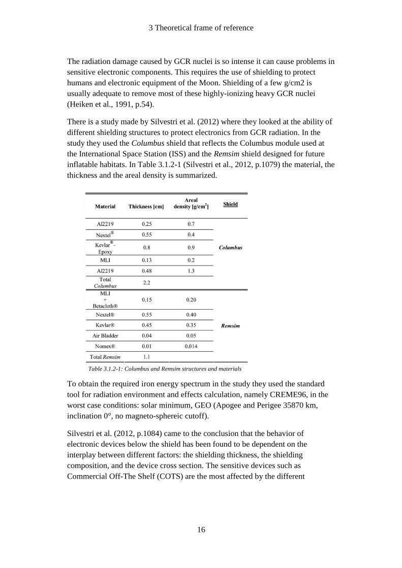
There is a study made by Silvestri et al. (2012) where they looked at the ability of
different shielding structures to protect electronics from GCR radiation. In the
study they used the Columbus shield that reflects the Columbus module used at
the International Space Station (ISS) and the Remsim shield designed for future
inflatable habitats. In Table 3.1.2-1 (Silvestri et al., 2012, p.1079) the material, the
thickness and the areal density is summarized.
To obtain the required iron energy spectrum in the study they used the standard
tool for radiation environment and effects calculation, namely CREME96, in the
worst case conditions: solar minimum, GEO (Apogee and Perigee 35870 km,
inclination 0°, no magneto-sphereic cutoff).
Silvestri et al. (2012, p.1084) came to the conclusion that the behavior of
electronic devices below the shield has been found to be dependent on the
interplay between different factors: the shielding thickness, the shielding
composition, and the device cross section. The sensitive devices such as
Commercial Off-The Shelf (COTS) are the most affected by the different
Table 3.1.2-1: Columbus and Remsim structures and materials
3 Theoretical frame of reference
17
shielding structure, thickness, and used method. The Soft Error Rate (SER)
reduction has been found to be larger for Columbus as compared to Remsim due to
the difference in the transmitted secondaries, especially for extremely sensitive
devices as mentioned before.
Space radiation effects
Developing reliable space systems for lunar exploration and infrastructure for
extended duration operations on the lunar surface requires analysis and mitigation
of potential system vulnerabilities to radiation effects on materials and systems
(Joseph I, Minow et al., 2007, p.1).
The effects of radiation environment in interplanetary space must be taken into
account for spacecraft design. The dominant components of the ionizing radiation
environment in interplanetary space are galactic cosmic rays (GCR) and solar
cosmic rays (SCR) (Adams, James H., Jr., 2008, p.1). Another event that causes
effects on spacecraft materials is meteoric particles. As a result of the space
environment factors mentioned above, various physic-chemical processes occur in
spacecraft materials and equipment components and lead to the deterioration in
their operating parameters. The effects of radiation depend on the type, intensity
and energy of the radiation, the type and temperature of the irradiated material and
some other factors. More than 50 % of malfunctions in spacecraft equipment are
caused by cosmic factors, according to the experts.
Radiation effects produced by the action of the fluxes of charged particles on the
spacecraft depend on the total absorbed space radiation dose and the dose rate.
The most critical effects to microelectronic and optoelectronic components are
single charged particles. The effects of these particles depend on the dose rate,
because their appearance is related to a large energy release in a restricted volume
of material during a short period of time (L.S. Novikov, et al., 2008, p.199).
Shielding
Shielding is arguably the main countermeasure for the exposure to cosmic
radiation during interplanetary exploratory missions. However, shielding of
cosmic rays, both of galactic or solar origin, is problematic, because of the high
energy of the charged particles involved and the nuclear fragmentation occurring
in shielding materials.
High-energy radiation is very penetrating. A thin or moderate shielding is
generally efficient in reducing the equivalent dose, as the thickness increases,
shield effectiveness drops. This is the result of the production of a large number of
secondary particles, including neutrons, caused by nuclear interactions of the
GCR with the shield (P.Spillantini, et al., 2005, p.14).

3 Theoretical frame of reference
18
Complicating factors
Radiation effects in spacecraft materials are very complicated. It is difficult to
analyze the effects because the compositions and structures of many materials
used in the spacecraft constructions are complicated (L.S. Novikov, et al., 2008,
p.202).
The formation of radiation defects under cosmic ionizing radiation has several
special features. The defects produced by different radiation components interact
between themselves and also with initial defects of the irradiated structure, with
the result that various synergetic effects occur (L.S. Novikov, et al., 2008, p.203).

3 Theoretical frame of reference
19
3.1.3 Previous rover designs
by Tobias Johannesson & Karl Hansson
This section describes already existing rovers that has driven in another celestial
body. It describes how they are built and what kind of mission they were made
for. The data is collected from different articles and JPL’s and NASA’s own
database.
Lunokhod 1
The first rover ever to drive on another celestial body was Lunokhod (“moon
walker” in English) and was constructed by the Russians. The rover was
approximately 2,3 meters long, 1,5 meters wide, weight approximately 800 kg and
was a remote controlled vehicle that could run at a maximum speed of 2 km/h. It
could drive 37 km before it needed recharging. Lunokhod had eight rigid-rim wire
mesh wheels with bicycle-type spokes. (Vivake Asnani, 2007) The rover was
powered by solar power during the day and at night it parked and relied on
thermal energy from polonium-210 radioisotope heater to survive the cold (-150
℃).
Lunokhods first mission was Luna 17 that launched in November 1970 and after a
successful landing on the moon it drove 10,5 km during the following ten months
and sent back valuable data concerning the composition of the regolith, close up
views and local topography and important engineering measurements of the
regolith. (NASA) Lunokhod carried a French-built laser reflector and both the
Russians and the French ranged to the reflector during the first lunar night,
followed by another success in February 1971. After this they never got real
contact with the rover until Mars 2010. (Murphy, 2010).
Figure 3.1.3-1: Lunokhod 1

3 Theoretical frame of reference
20
Lunokhod 2
Two years after Lunokhod first touched the lunar surface the Russians launched
mission Luna 21 that delivered a new rover, Lunokhod 2, to the moon. Lunokhod
2 was an upgraded version of Lunokhod1 with better cameras and an improved
scientific payload. Like its predecessor it was driven by engineers on Earth during
the day and parked at night. Lunokhod explored the moon for about four month
and had driven a distance of 37 km when unfortunately the mission was brought
to an early end due to overheating.
The two Lunokhod rovers showed the value of robotic explorers on the surface of
another world, but it would another 24 years before the next robotic rover,
Sojourner, drove on another world, this time Mars. (NASA)
Lunar Roving Vehicle (LRV)
Before 1971 the United States had accomplished three successful manned lunar
landings and totally explored a distance of approximately 7 km, compared to the
Russians that explored approximately 10,5 km with an unmanned rover. In July
1971 the United States launched Apollo 15 that carried America’s first vehicle
that drove on another celestial body, Lunar Roving vehicle (LRV). The LRV was
developed by NASA and built by The Boeing Company. Under development and
construction the main concerns were simplicity of design and operation and light
weight. The LRV is 3,1 m long, slightly more than 1,83 m wide, 1,14 m high and
has a 2,29 m wheelbase. It weighs about 2130 N, including tie down and
unloading systems, and can carry a weight of about 4800 N, including the weight
of two astronauts and their Portable Life Support System.
The LRV has four wheels and each wheel is individually driven by an electrical
motor. This makes the vehicle’s top speed 9 to 13 km/h depending on the terrain.
The rover is powered by two no rechargeable silver-zinc batteries and has two
complete battery systems that each can provide power for operation. The LRV is
manually operated by one of the two astronauts and normally steered by both
front and rear wheels in a double Ackerman arrangement. The wheels are woven
of zinc-coated piano wire with a spun aluminum hub and a titanium bump stop.
Chevron-shaped treads of titanium are riveted to the wire mesh around each
wheel’s outer circumference and cover approximately 50 percent of the soil
contacting surface. Each wheel weighs 53.3 N.
The drive motors are direct-current series, brush-type motors which operate from
a nominal voltage of 36 V. Each motor is thermally monitored by an analog
temperature measurement from a thermostat at the stator field. In addition each
motor contains a thermal switch which closes on increasing temperatures at
204 ℃.

3 Theoretical frame of reference
21
The basic chassis is fabricated from 2219 aluminum alloy tubing and welded at
the structural joints. The tubular members are milled to minimum thickness
consistent with the bending moment and shear diagrams. The chassis is suspended
from each wheel by a pair of parallel triangular suspension arms connected
between the Rover chassis and each traction drive. (Nicholas C. Costes, 1972).
Sojourner
Sojourner is the first unmanned rover to successfully land on another planet. The
rover landed on Mars in June of 1997 after spending seven months traveling
through space. Sojourner was part of the NASA Mars Pathfinder mission.
Sojourner is a lightweight rover measuring only 0,63 meters long by 0,48 meters
wide and whit a total weight of 11,5 kg. The small rover is a six-wheeled vehicle
of a rocker bogie design that allows driving over rough terrain with a wheel
diameter of 0,13 meter and a top speed of 0,4 meter per min.
The rover is power by a 0,22 sqm solar panel and back up by a lithium battery,
this provides up to 150Whr of energy, normal driving power that’s require for a
rover this size is 10W.
Figure 3.1.1-2: Lunar Roving Vehicle (LRV)
Figure 3.1.3-3: Sojourner

3 Theoretical frame of reference
22
The inner components of the rover are not design to withstand ambient Mars
temperatures, -110 degC during a Martian night, the solution is to place all the
sensitive components inside a warm electronics box, WEB. The warm electronics
box houses the computer, batteries, and other electronic components. The box is
designed to protect these components and control their temperature. Thermal
control is achieved through the use of gold paint, aero gel insulation, heaters,
thermostats, and radiators. This makes sure a temperature inside the WEB
between -40 degC and 40 degC at all time. (JPL).
Spirit and Opportunity
In 2000 the decision was made by NASA to send another two rovers to Mars,
spirit and opportunity. The twin rover landed successfully on opposite side of
Mars early in 2004.
The designs of these rovers are based on the earlier sojourner rover. Some of the
carried-over design is the six wheels and a rocker-bogie suspension for driving
over rough terrain, solar panels and rechargeable batteries for power and the warm
electronics box (WEB) for housing sensitive components inside the rover. But
these new rovers are a lot bigger, measuring 1,6 meters long, 2,3 meters wide and
with a total weight of 174 kg etch. (NASA/JPL, 2005)
For driving the twin rovers have six wheels and a rocking-bogie suspension, etch
wheel have it individual motor for power and the two front wheels and the two
rear wheels can turn, this enable the rovers to turn in place. The vehicles have a
top speed of 50mm/s. The vehicles are also design to safely operate at tilts up to
30 deg but are constructed to withstand tilts up to 45deg whiteout falling over.
Power to the rover is provided by the solar arrays, generating up to 140 W of
power under full Sun conditions. The energy is then stored in rechargeable
batteries.
The chassis of the rover is based on a box design. The chassis contains the WEB,
which works the same way as on the previous rover Sojourner, on top of the WEB
is the triangular rover equipment deck, on which is mounted the Pancam mast
assembly, high gain, low gain and UHF antennas. Attached to the two forward
sides of the equipment deck are solar arrays that are level with the deck and
extended outward with the appearance of a pair of swept-back wings. Attached to
the lover front of the WEB is the instrument deployment device, a long hinged
arm that protrudes in front of the rover. At top of the Pancam mast assembly is the
mount for a panoramic camera and cameras for navigations, at a height of about
1,4 meter.

3 Theoretical frame of reference
23
Communications with Earth are in X-band via the high gain directional dish
antenna and the low gain omni-directional antenna. Communications with orbiting
spacecraft are through the ultra-high frequency, UHF, antenna.
Curiosity Curiosity is the forth and the biggest rover on Mars as of this day with roughly the
same size as a small car. Curiosity landed safely in august of 2012.
Curiosity also has some key components form its predecessor like the six wheels
and a rocking-bogie suspension, a Warm electronics box for housing sensitive
components, high gain, low gain and UHF antennas for communication, a mast on
its equipment deck with a panoramic camera and cameras for navigations and a
long arm for execute a various of experiments on the Martin surface.
Curiosity is roughly the same size as a small car measuring 3 meters long, 2,7
meters wide, 2,2 meters height and a total weight of 900kg. This makes Curiosity
by far the biggest unmanned rover to set its wheels on another celestial body.
This rover is based on the same box design as its predecessor with a WEB to
house sensitive components. Curiosity also cares a science laboratory to be able to
carry out more advance experiments. The rover is based on the same six wheels
and rocker-bogie suspensions as the earlier rovers, with an individual motor for
power to each wheel and steering at the two wheels at the front and the two
wheels at the rear. Curiosity has a top speed of 4 centimeter per second.
Curiosity carries a radioisotope power system that generates electricity form a
heat of plutonium’s radioactive decay. This power source gives the mission an
Figure 3.1.3-4: Spirit/Opportunity

3 Theoretical frame of reference
24
operating lifespan on Mars surface of at least a full Martian year, almost 2 Earth
years. This also providing significantly greater mobility and operational flexibility
it also enhanced the science payload capability.
Figure 3.1.3-5: Mars Science Laboratory, Curiosity rover

3 Theoretical frame of reference
25
3.2 Field research and development
JPL is on the cutting edge of today's technology. When a project of this kind is
launched, it's common for the required technology to be developed during the
project. This leads to long-term planning, since the technology that is developed
must be tested under a long period of time and verified as reliable, before it can be
used in an operational stage of the project.
NASA and JPL are open organizations in the sense that they welcome students
and companies to submit their ideas and designs. This is a way to increase
creativity and advance the face of technology at a higher pace than would have
been possible inside one closed organization.
3.3 Overview of relevant literature
Lunar Sourcebook: A User's Guide to the Moon (Grant H. Heiken, David T.
Vaniman and Bevan M. French (eds.), 1991) was discovered during a review of
relevant literature. This is a very comprehensive collection of documents and data
collected during American and Russian lunar missions. Despite the early
publication year (1991), the data are still accurate since nothing in the lunar
environment has changed and there have been no recent lunar missions. The book
is written and edited by scientists active in every field of lunar research, all of
whom are veterans of the Apollo program. The contributors are from universities,
national laboratories, industry, and NASA.
The NASA Technical Reports Server (NTRS) has been used to acquire more
recent technical data. The NTRS is a valuable resource for researchers, students,
educators, and the public to access NASA's current and historical technical
literature and engineering results. Over 500,000 aerospace-related citations, over
200,000 full-text online documents, and over 500,000 images and videos are
available. NTRS content continues to grow as new scientific and technical
information (STI) is created or funded by NASA. The types of information found
in the NTRS include: conference papers, journal articles, meeting papers, patents,
research reports, images, movies, and technical videos.

4 Results
26
4 Results
This chapter reviews and explains the results which have been established
throughout the project.
4.1 Project definement
To be able to follow the selected methodology and conduct the work with good
structure, the project is defined in the following section.
4.1.1 Product definition
This section corresponds with the first step in "Principkonstruktion" (Fredy
Olsson, 1995), see chapter 2.2.
Product
The product definition is shown in Table 4.1.1-1.
The rover is divided into the three following units and sub-units:
1. Chassis
Internal chassis - Warm Electronics Box (WEB), hold and protect
vital electrical components
External chassis - Withstand external forces and provide mounting
points for external parts
2. Antenna deployment system
Deployment mechanism
3. Mobility system
Suspension
Wheels
Table 4.1.1-1: Product definition table

4 Results
27
Process
The purpose of this process overview is to illustrate the main process of the DALI
- Deployment rover.
Surroundings
The rover is placed in a lunar module which will be carried to low earth orbit
(LEO) by an Atlas V rocket system. The lunar module will land at the far side of
the Moon, and deploy the roving vehicle. This rover will then carry out the current
mission.
During launch, flight and landing the rover can be subjected to forces up
to 20 times that of Earth's gravity (20 g)
Outside Earth's atmosphere and at the lunar surface, the rover will be
exposed to various radiation types. Mainly Solar Cosmic Rays (SCR),
Galactic Cosmic Rays (GCR) and solar winds (see chapter 3.1.2)
A suitable location for this kind of mission could be the lunar mare
Tsiolkovsky, at the farside of the Moon (see chapter 1.1.1). Surface
conditions of lunar maria are presented in chapter 3.1.1.
Human interaction
The only type of human interaction a mission ready rover of this type will have, is
initial loading in lunar module and remote access for managing and data
upload/download.
Convert from cargo mode
•Deploy mobility system
•Unfold solar panels
•Raise camera
Leave lunar landing module
Communications check
Antenna roll pick-up
•Navigate to stationary antenna cartridge
•Pick up antenna roll
Rove to deployment site
•Plot route
•Locate in center
Antenna deployment
•Deploy outwards from center point
Fetch new antenna roll
Repeat until all six antennas are deployed
•Deploy antennas in a star pattern
Act as communication unit in the center of the deployed antennas
Figure 4.1.2-1: Process overview

4 Results
28
Economic aspects
The project definition specifies that the economic aspects will not be taken into
consideration.
4.1.2 Project design specifications
The following specifications apply to the entire project as well as the rover's units
and sub-units.
1. Equipped with elevated camera
2. The rover must house and protect vital electrical components
Communication unit
Remote managing and controlling
3. Rover and lunar landing module must meet the space requirements of the
Atlas V 401-4S (4x9.4 m, nose cone)
Compact design
4. Rover design must withstand forces up to 20 g
5. Maximum ground pressure at 3 kPa
6. The rover must withstand the lunar radiation environment
Solar wind
SCR
GCR
7. The rover must withstand temperature differences of ±125 °C
8. The antennas shall be deployed in a star-pattern
9. If an antenna malfunctions or is destroyed, a new antenna can be
deployed
10. 8/10 stations must be operational within 90 days
11. 7/10 stations must remain operational after six months

4 Results
29
4.2 Project results
4.2.1 Deployment strategy selection process
This section explains the process of selecting the antenna deployment concept, or
strategy. Since this was a very important step in the overall project, a lot of
thought went into the selection process. The selection is supported by the
methodology described in chapter 2.2.
Brainstorming
To obtain a diverse set of ideas and concepts, each sub-group brainstormed
separately. The different ideas that came up were brought to a brainstorming
session with the entire group.
Basic evaluation
Through brainstorming, five different strategies/concepts were selected for a basic
evaluation.
Concept 1: Deployed by rover
The first and most basic system we discussed, which was also
proposed in the mission objective that was handed out. It would
involve the rover picking up the antenna roll from a stationary
cartridge, rove to the deployment site, and deploy the antenna by
rolling it out as the rover moves forward.
Concept 2: Inflatable system
Deploying the antennas using a system where compressed gas is
used to inflate a plastic "bag" containing the actual antenna. This
would result in a concept similar to a "party horn blower".
Concept 3: Anchor system
Two sub-concepts:
1. The rover locates itself in the center of the deployment site,
and then launch an anchor 100m in the antennas direction.
This anchor would be equipped with a motor capable of
pulling the antenna from the roll-out mechanism on the
rover to its deployed position.
2. The rover locates a point which would correspond with an
end point of one deployed antenna. Instead of launching an
anchor, the rover would drop the anchor at this position,
and then locate itself in the center of the deployment site.
As well as the other sub-concept, the anchor would be
equipped with the same type of pulling-system, able to
deploy the antenna.
4 Results
30
Concept 4: Pushing system
This would mean that the rover locates itself in the center of the
deployment site, lower itself down to ground level, and then use a
pushing system to deploy the antenna. This process would demand
that the antenna roll is equipped with wheels, which makes it
possible for the antenna to "glide" across the surface
Concept 5: Autonomous antenna rolls
A system where the antenna rolls are self-propelling. The rover
would pick-up an antenna roll from the stationary cartridge, rove to
the deployment site and the antenna roll will deploy itself. This
procedure is repeated six times, until a full star-pattern is deployed.
Using primitive methods such as common sense and experience, three of the five
concepts were excluded during the basic evaluation. Concept 1 and 5 were
selected for further evaluation and development.

4 Results
31
Further development and evaluation
In order to compare the two remaining concepts, a table with advantages and
disadvantages was put together.
Advantages
Concept 1 Concept 5
Lighter/smaller antenna rolls
Shorter roving distance
More stable/secure deployment
Less time consuming process
Ability to fetch new antenna rolls
Easier to equip with camera
Easier to equip with solar panels
Higher ground clearance
Disadvantages
Concept 1 Concept 5
Longer roving distance Larger, heavier antenna rolls
Heavier rover design Unstable deployment
Damage to the antenna renders the rover useless
Limited space for internal components
More difficult to equip with solar panels
More difficult to equip with camera
Table 4.2.1-1: Comparative table, Concept 1 and Concept 5
In the comparison, Concept 5 has several disadvantages. In order to solve these
problems the concept had to be reconstructed.
To secure a stable deployment and have the ability to fit solar panels on
the rover, some kind of support wheels are needed.
Compensating for the limited space inside the rover, makes the entire
rover bigger and heavier.
A heavy rover will need bigger power supply and solar panels.

4 Results
32
After solving most of the problems, Concept 5 turns out to be very similar to
Concept 1.
To exclude Concept 5 and continue the development of Concept 1 was considered
the most advantageous solution.
Concept 1 - Improvements
Even though Concept 1 was considered the most suitable, it required further
development in order to fail safe the process. Figure 4.2.1-1 illustrates the most
basic flow chart of Concept 1.
Figure 4.2.1-1: Basic flow chart of Concept 1
The following questions and shortcomings had to be taken in consideration for
further development:
What if the rover breaks down during deployment?
If the internal communication unit malfunctions, the station is useless.
Requires one rover for each station.
The rover can only perform the task of antenna deployment and is unable
to provide support for other stations.
To eliminate these shortcomings, and reach a process with a high level of fail
safety, the concept underwent a series of improvements.
Antenna roll pick-up Rove to deployment
site
Antenna deployment
Fetch new antenna roll
Repeat until all six antennas are
deployed
Act as communication unit in the center of the deployed antennas

4 Results
33
A solution with an external communication unit would improve the process on
several levels:
Since the communication unit is deployed prior to the antenna
deployment, the telescope is partly functional at the moment the first
antenna is deployed.
If the rover breaks down during the mission, a rover from another station
can resume the remaining tasks.
One rover can deploy several stations.
If the communication unit malfunctions, the rover will be able to fetch and
deploy a new unit.
A flow chart of the improved concept was put together in order to illustrate the
process and facilitate the making of a Process FMEA.
Process FMEA
Failure Modes and Effects Analysis (FMEA) is a method used for predicting
failure modes, their causes and resulting effects. Due to the high level of fail-
safety this project demands, a flow chart for the process and a Process FMEA was
made in order to secure the system reliability in an early stage of the project. The
Process FMEA is to be maintained throughout the project and constructed in
accordance with MIL-STD-1629 - Procedures for Performing a Failure Modes,
Effects and Criticality Analysis. The Process FMEA will be passed on to future
projects. See appendix 1.
Communication unit pick-up
Rove to deployment site
Deploy communication
unit
Antenna roll pick-up
Antenna deployment
Fetch new antenna roll
Repeat until all six antennas are
deployed
Standby for new tasks
Figure 4.2.1-2: Flow chart of improved Concept 1

4 Results
34
4.2.2 Mobility system concept selection process
The selection is supported by the methodology described in chapter 2.2.
Mobility system design specifications
A list of the design specifications concerning the mobility system was put together
in order to compare the different concepts. The specifications were divided into
requirements and desired specifications, where the desires were weighted against
each other in “Table 4.2.2-1” to determine the weight factor of each desired
specification.
Explanatory: 1) 7 > 8 = 2 | 7 = 8 = 1 | 7 < 8 = 0
C: Correctional factor 2) Compare 7 & 9, 7 & 10, 7 & 11
P: Individual points
3) Compare 8 & 9, 8 & 10, etc.
F: Weight factor 4) Add vertically and convert to negative
5) Add horizontally = P 6) ∑P = n × n (n = number of desired specifications)
7) F = P / ∑P 8) ∑F = 1
7 8 9 10 11 C P F
7 1 1 1 1 1 5 0,2
8 -1 1 2 2 3 7 0,28
9 -2 2 1 5 6 0,24
10 -5 1 7 3 0,12
11 -5 9 4 0,16
Total: 25 1
Table 4.2.2-1: Comparative weight table

4 Results
35
Description Category
1 Withstand forces up to 20 g Required
2 Maximum ground pressure at 3 kPa Required
3 Withstand temperature differences of ±125 °C Required
4 Enable deployment of rover Required
5 Able to rotate around its own Z-axis Required
6 Reduce the motion of the chassis by 50%* Required
*Compared to a rigid suspension system F
7 Antilock drive system Desired 0.20
8 Efficient weight distribution Desired 0.28
9 As few moving parts as possible Desired 0.24
10 Capable of driving in angular slopes up to 30° in any direction
Desired 0.12
11 Capable of travelling over obstacles ≤ wheel diameter
Desired 0.16
Table 4.2.2-2: Mobility system design specifications summary
Research and brainstorming
To achieve the best drive system for this project, a lot of time was spent on
research and brainstorming. Initially, the focus of the research was kept on
previous rovers built by JPL, but was later extended to rovers and robots
constructed by different companies and civilians.
The result of the research and brainstorming was 11 different concepts and sub-
concepts of the drive system.
Basic evaluation
Since several of the different concepts share similar construction ideas, they were
treated in groups in this first step of evaluation. The following grouping was used:
1. Concept 1
Basic suspension consisting of four wheels, similar design to
NASA's K10 rover. The vehicle is equipped with all wheel
steering, which enables it to rotate around its on z-axis. See
Appendix 2
2. Concept 2 & 3
A version of "Concept 1" where both pair of wheels have
adjustable suspension. Instead of turning the wheels, steering is
achieved by driving the wheels at different speeds. See Appendix
2
3. Concept 4 & 5
Using a rocker-bogie suspension system with six wheels, all wheel
drive and steering on both the front and rear wheels. This

4 Results
36
arrangement has been used on all three of NASA's Mars missions
(Mars Pathfinder, Mars Exploration Rover and Mars Science
Laboratory). This is currently the favored design by NASA, partly
because it can reduce the motion of the main vehicle body, by up
to 50%. See Appendix 2
4. Concept 6
A version of "Concept 4 & 5" where the rear wheels have rigid
suspension, while the other four wheels are suspended in a
standard bogie system. See Appendix 2
5. Concept 7
This suspension system consists of four or more wheels, that are
individually operated. By driving each wheel with its own specific
setting and controlling the vertical position, it should provide a
suspension system which is able to keep the rover level at all times
during antenna deployment. A similar system can be seen on
NASA's Next Generation Moon Rover, the Space Exploration
Vehicle (SEV). See Appendix 2
6. Concept 8
Instead of using wheels, this system is equipped with continuous
tracks. "Concept 8" is fitted with a standard set of tracks (one
continuous track on each side), where steering is accomplished by
driving the tracks in opposite directions or at different speeds. See
Appendix 2
7. Concept 9
As well as "Concept 8", this system uses continuous tracks.
Instead of using a standard set of tracks, this concept is equipped
with four set of tracks. Steering is made possible by turning the
entire track, instead of driving it at different speeds or directions.
See Appendix 2
8. Concept 10
Using a similar system which can be seen on the ATHLETE rover
system designed by JPL. It's designed to be able to walk or roll
over many different types of terrain. See Appendix 2
9. Concept 11
This concept is based on a walking system, which uses six
articulated legs as its means of ground propulsion. See Appendix 2
To achieve a stable antenna deployment the suspension must provide a certain
degree of adjustability. Without this capability the antennas run the risk of being

4 Results
37
subjected to a level of sideways tension, which is not allowed. Based on this
reasoning, "Concept 1" was discarded.
Since the current mission demands a suspension which enables high precision
steering, the concepts involving tracks (Concepts 8 & 9) were ruled out. A
continuous track system makes it more complicated to achieve a steering
precision equivalent to that of a wheel based system. The same reasoning was
applied to exclude concepts 2, 3 and partially “Concept 11”, which all suffers
from deficient steering systems. Together with the high level of complexity a
walking system would imply, the decision to exclude “Concept 11” from further
development and evaluation was logical.
The level of complexity of "Concept 10" in proportion to the current mission
objective, form the basis of the decision to exclude this concept from further
development and evaluation.
Through the basic evaluation, seven concepts were excluded, and four concepts
(4, 5, 6 & 7) remained for a more detailed evaluation.
Detailed evaluation
This stage in the selection process was performed by constructing a table where
each of the four concepts was equally treated. The different numbers in "Table
4.2.2-3" corresponds to each of the requirements and the desired specifications, all
of which are presented in "Table 4.2.2-2". The method of ranking each concept is
subjective and based on assessments and group discussion.
The requirements (1-6) were assessed in a manner of "pass" or "fail", where
"pass" is indicated by "" and "fail" by "X". The desired specifications (7-11)
were rated from 1-5 depending on how well the concepts meet the desired
specifications. These ratings were then multiplied by the weight factor from
"Table 4.1.1-1" to acquire a comparative value.
Prior to the construction of the mobility system concept selection table (Table
4.1.1-3), an assessment was made regarding which concept was considered to be
the most suitable. The aim of this discussion was to find the most well-balanced
concept between purpose, performance and complexity. This resulted in a
preliminary selection of "Concept 4 & 5". To support this reasoning "Table 4.2.2-
3" was constructed.
The reason that desired specification no. 7 is excluded in the selection table (Table
4.2.2-3) was that the lack of knowledge within the group made it very difficult to
assess the probability of successfully integrating a system of this kind.

4 Results
38
Concept 4 & 5 Concept 6 Concept 7
1
2
3
4
5
6 X
7 - - -
8 4 × F8 3 × F8 5 × F8
9 4 × F9 5 × F9 1 × F9
10 4 × F10 4 × F10 5 × F10
11 3 × F11 2 × F11 4 × F11
Total: 3,04 2,84 2,88
Table 4.2.2-3: Mobility system concept selection table
The mobility system concept selection table (Table 4.2.2-3) verifies the
preliminary concept selection, which was made prior to "Table 4.2.2-3". Since
these two results are in correspondence with one another, the final concept
selection was "Concept 4 & 5". See Appendix 3
To achieve the most suitable concept design, this theoretical design will be subject
to a comprehensive development stage. During this period the concept will be
optimized, realized, tested and simulated in a 3D-environment, to prevent
otherwise undetected issues and provide data for basic prototyping.

4 Results
39
4.3 Further development of the rocker-bogie suspension system
This chapter explains the process of the further development of our chosen
concept for the suspension, a rocker-bogie suspension system. Each section in this
chapter treats a different aspect of the process, from modeling and visualization to
analysis and prediction of failure.
4.3.1 Modeling
Since this project doesn't involve detailed engineering and part design, the
purpose of the 3D-modeling is to visualize the concept and provide data for basic
analysis. This early stage in the design process demands a 3D-model with a
structure which enables future modification.
The 3D-model, which is presented below (Figure 4.3.1-1), is pure visualization.
No work has gone into the structural or part design.
Figure 4.3.1-1: Rocker-bogie suspension, 3D-model
4 Results
40
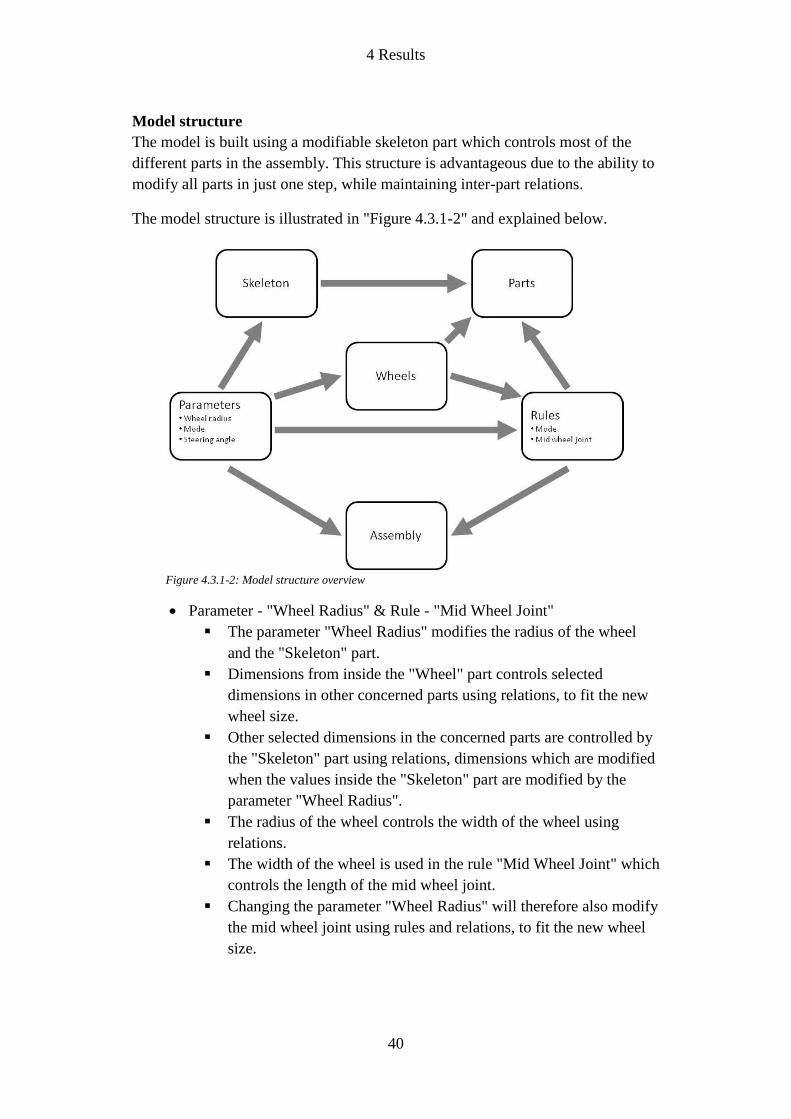
Model structure
The model is built using a modifiable skeleton part which controls most of the
different parts in the assembly. This structure is advantageous due to the ability to
modify all parts in just one step, while maintaining inter-part relations.
The model structure is illustrated in "Figure 4.3.1-2" and explained below.
Parameter - "Wheel Radius" & Rule - "Mid Wheel Joint"
The parameter "Wheel Radius" modifies the radius of the wheel
and the "Skeleton" part.
Dimensions from inside the "Wheel" part controls selected
dimensions in other concerned parts using relations, to fit the new
wheel size.
Other selected dimensions in the concerned parts are controlled by
the "Skeleton" part using relations, dimensions which are modified
when the values inside the "Skeleton" part are modified by the
parameter "Wheel Radius".
The radius of the wheel controls the width of the wheel using
relations.
The width of the wheel is used in the rule "Mid Wheel Joint" which
controls the length of the mid wheel joint.
Changing the parameter "Wheel Radius" will therefore also modify
the mid wheel joint using rules and relations, to fit the new wheel
size.
Figure 4.3.1-2: Model structure overview

4 Results
41
Parameter & Rule - "Mode"
The parameter "Mode" allows the user to select whether the
assembly should be displayed in "Deployed mode" or "Cargo
mode".
The parameter activates a rule which in turn controls assembly
constraints.
The rule is written to modify the assembly constrains differently
depending on which wheel radius is used.
Parameter - "Steering Angle"
The parameter "Steering Angle" controls the assembly constraints
which determine the angular position of each wheel.
Relations ensures that the steering angle of the front and rear
wheels are equal.
4.3.2 Analysis
At this stage, a detailed analysis is redundant, due to the lack of detailed
engineering and part design. The purpose of this analysis is to generate an
approximate result for future modifications. The interesting areas to analyze, at
this time, are weight distribution and stress concentrations in the design.
Figure 4.3.2-1 and 4.3.2-2 shows a static analysis of a rocker-bogie suspension,
with a downwards force acting on the chassis joint.
The two figures show a relatively even distribution of weight and mechanical
stress. The stress concentrations only appear in expected areas, which are the
chassis- and bogie joints.
Figure 4.3.2-2: Bottom view of a static case
Figure 4.3.2-1: Right view of a static case

4 Results
42
Figure 4.3.2-3 shows a static analysis of one of the rover wheels, with loads
simulating an operational environment. The stress concentrations appear in
expected areas, which are the load bearing spokes. The spokes transfers some of
the stress onto the tread of the wheel, as shown to the right in Figure 4.3.2-3.
4.3.3 Simulation
A series of simulations has been made in order to ensure the functionality of the
suspension system. The areas that have been controlled are:
No interference between different parts of the suspension
No interference between the suspension system and other parts of the
rover
The suspension system enables the rover to rotate around its own Z-axis
Figure 4.3.2-3: Static analysis of rover wheel

4 Results
43
4.4 Discussion
4.4.1 Mobility system concept - Rocker-bogie
By following the methodology presented in section 2.2, "Concept 4 & 5" turned
out to be the most suitable concept. The required design specifications demanded
a suspension system which could deliver a high level of stability and prevent the
rover from suddenly and dramatically change positions. This results in that the
antenna deployment system won't have to correct the same amount of rover
movement as would be the case with a rigid suspension system.
Since the antenna deployment system is designed to compensate the movements
of the rover, the decision was made to keep the complexity of the rocker-bogie
suspension at a minimum while maintaining required specifications. This
reasoning is behind the decision to exclude the development of a more complex
rocker-bogie suspension which would be more effective in reducing the
movement of the rover.
4.4.2 Material selection
Due to the lack of detailed engineering and part design, the project group finds
that a selection of material is redundant at this stage. A material selection process
require information regarding actual loads, detailed part design and weight
requirements. All of which does not exist at this time.
In Dark Ages Lunar Interferometer (DALI): Deployment-rover - Chassis (Johan
Winberg & Tomislav Stanimirovic, 2013), a detailed material selection
process/method is presented. This can be applied to the mobility system in a
future stage of this project.
4.4.3 Functional FMEA
The Failure Modes and Effects Analysis in this project shall be performed in
accordance with Standard for Performing a Failure Mode and Effects Analysis
(FMEA) and Establishing a Critical Items List (CIL) (DRAFT), which states:
"A Functional FMEA is performed as soon as sufficient information is available
to construct a functional block diagram of the item under development. In order to
perform a Functional FMEA, the following information, as a minimum, is
required:
A functional block diagram of the item under development broken down to the
subsystem and component level."
Since the project at this stage is not at a component level, the functional FMEA is
to be performed at a future stage of this project.

5 Conclusions
44
5 Conclusions
The results presented in chapter 4 shows that a mobility system based on a rocker-
bogie suspension is able to meet the mobility system design specifications (Table
4.2.2-2). However, to ensure that the presented concept in this project meets the
required specifications, further development is needed.
To be able to draw conclusions, the results in chapter 4 are measured against the
mobility system design specifications (Table 4.2.2-2). Presented below is a list of
the drawn conclusions:
1. Withstand forces up to 20 g
Will be a matter of part design and material selection
2. Maximum ground pressure at 3 kPa
Total weight of the rover and wheel dimensions are needed to
calculate the ground pressure. Using the calculations in section
3.1.1 one can calculate the ground pressure and be able to optimize
the wheel dimensions to meet the ground pressure specification.
3. Withstand temperature differences of ±125 °C
Will be a matter of part design and material selection
4. Enable deployment of rover
The suspension system concept is designed to be able to convert
from cargo- to deployed mode. This is still a concept, and further
part design and detailed engineering are required to develop an
operational system.
5. Able to rotate around its own Z-axis
The suspension design allows the rover to rotate around its own Z-
axis.
6. Reduce the motion of the chassis by 50%
The rocker-bogie suspension is designed to reduce the motion of
the chassis. Further development and simulations are needed to
ensure that the concept meet the specification.
7. Antilock drive system
Advanced mechanical engineering is required to investigate the
possibility of implementing a system of this kind.
8. Efficient weight distribution
The analysis (Figure 4.3.2-1 and 4.3.2-2) shows a relatively even
weight distribution with the rocker-bogie suspension system.
9. As few moving parts as possible
Will be a matter of part design

5 Conclusions
45
10. Capable of driving in angular slopes up to 30° in any direction
The suspension design allows the rover to drive in angular slopes,
however total weight and center of gravity of the rover are
important parameters to determine the slope capabilities.
11. Capable of travelling over obstacles ≤ wheel diameter
The suspension design allows the rover to travel over obstacles ≤
wheel diameter.
5.1 Discussion
At first glance it may seem like most of the requirements are not met by the
developed concept. At this stage, that is the case. However the created and
collected data up to this point provides a well worked-out foundation as a starting
point for future work and development. In our point of view there are no
indicators of shortcomings which would cause the concept to fail the
requirements, during future development.
One of the most important aspects of the rover, is that it must be able to perform a
stable antenna deployment. The issue which arose at an early stage of the project,
was where the motions caused by lunar terrain should be compensated for. The
decision was made for the deployment system to absorb most of these
movements. The basis of this decision was a question of design complexity and
the level of fail safety. To absorb the movements in the mobility system would
involve a much higher level of complexity, than to absorb the same movements in
the deployment system. To facilitate the process of designing a deployment
system capable of absorbing the movements caused by the lunar terrain, the
decision was made to develop a mobility system concept which would reduce
some of the motion of the rover and prevent sudden and dramatic movements. We
draw the conclusion, which is also supported by the selection process, that a
rocker-bogie suspension system would be ideal for this purpose.
At an early stage in the project a decision had to be made regarding the number of
antenna rolls that the rover would pick up and carry each time. Either pick up one
antenna roll and deploy it, or pick up two-six rolls each time and deploy one by
one. Since the antenna rolls doesn't exist, the project group decided to assume that
picking up two or more rolls each time would require the rover to be too big and
too heavy. From this we can draw the conclusion that the total roving distance
will be far greater than it would be if the rover only had to travel the distance once
instead of six times. Due to this fact it is possible that the total power consumption
also is greater than it would be to power a larger and heavier rover for a shorter
amount of time. Despite these two aspects, we think that is was, at the time being,
the best decision. However, if more accurate data on the antenna rolls were to be

5 Conclusions
46
collected during future work, and the data indicates that the rolls can be made
relatively small and light, it might be appropriate to reconsider the antenna
deployment strategy and modify the design of the deployment system.

6 Critical review
47
6 Critical review
A Gantt-chart was constructed in the beginning of the semester, describing the
planning of the project, see Appendix 4. This planning has been a guideline for us
while working, and used to prevent us from prioritize unnecessary tasks and it has
been accurate during most parts of the project. However, halfway into the project
the stage "Prototype construction" was considered to be of secondary importance.
Instead of constructing a physical prototype for testing and visualization, the time
was used to create a more advanced digital mock-up for the same purposes.
At one of the meetings with our supervisor at JPL, Dr Ashitey Trebi-Ollennu, it
was suggested that we could study the architecture of a system involving several
autonomous units. At the time being, there was no time to put any work into that
kind of research. Perhaps this should have been brought up on one of our own
meetings in the beginning of the project. If this would have been the case, some of
the initial project research could have gone into that area, and given us a greater
understanding of a project of this kind.
We consider our product design specifications to be incomplete and/or
insufficient, due to our lack of knowledge and experience within the given field. If
the project is to continue next semester, and be more focused at part design and
detailed engineering; we think that it would be in the project's best interest if an
experienced individual, perhaps supervisor at JPL or at Halmstad University, was
to be more involved in the process of creating a more comprehensive product
design specification.
Overall we are very satisfied with the result of this project and the effort we put
in. We consider our work to be a solid foundation for future projects.
It has been an interesting journey and a great learning experience.
6.2 Environmental, economic and societal aspects
This section discusses the entire DALI project, and these are the aspects we
consider to be relevant.
From an environmental and economic point of view, the part of the project prior
to an operational interferometer at the far side of the Moon, is associated with
great risk and negative effects.
The funding required for completion is vast, which can be considered an uncertain
investment. However if the project is successful, the return might have a huge
positive impact on science and our society. One can only speculate in the effects
of the desired discoveries.

7 Future work
48
The environmental effects of a rocket launch are hazardous to the surrounding
nature. If the desired discoveries are taken into consideration, these environmental
effects are negligible in a greater perspective.
The mission on the lunar surface won't have any significant impact on the lunar
environment.
7 Future work
To make future projects at Halmstad University possible, the following list of
required future work has to be taken into consideration. The future progress is
divided into what the coming steps regarding the mobility system are, and what
competence the entire project needs for further development.
7.1 Mobility system
We consider the next steps in this project, regarding the mobility system, to be the
following:
Detailed part design
Material selection
Components selection
Comprehensive analysis and simulation
Testing with physical prototype
Functional FMEA
7.2 Project
We consider the following competence to be essential for future progress of this
project:
Mechanical engineering
Electrical engineering
Mechatronics engineering
Systems design

References
49
References
Lunar Sourcebook: A User's Guide to the Moon (Grant H. Heiken, David T.
Vaniman and Bevan M. French (eds.), 1991)
Lunar Soil Simulation and trafficability parameters (Carrier, 2006)
Lunar surface engineering properties experiment definition (James K. Mitchell,
Richard E. Goodman, Franklin C. Hurlbut, William N. Houston, D. Roger Willis,
Paul A. Witherspoon and H. John Hovland, 1971)
Applied imagination: Principles and procedures of creative problem solving (3rd
ed.) (Axel F. Osborn, 1963)
Preliminary Design of a Galactic Cosmic Ray Shielding Materials Testbed for the
International Space Station (James R. Gaier, Stephen Berkebile, Edward A.
Sechkar and Scott R. Panko, 2012)
Building a New Kind of Graded-Z Shield for Swift’s Burst Alert Telescope
(David W. Robinson, 2002)
Influence of Spacecraft Shielding Structures on Galactic Cosmic Ray-Induced
Soft Error Rate (Marco Silvestri, Emanuele Tracino, Roberto Destefanis, Cesare
Lobascio, Giovanni Santin and Philippe Calvel, IEEE Transactions on nuclear
science, vol. 59, no. 4, 2012)
Radiation Hardness Assurance for Space Systems (Christian Poivey)
Space radiation protection (R. W. Langley et al., 1970)
Space Environmental Effects on Spacecraft: LEO Materials Selection Guide
(Edward M. Silverman, 1995)
What Reliability Engineers Should Know about Space Radiation Effects (R.C.
DiBari)
Total Design: Integrated Methods for Successful Product Engineering (Stuart
Pugh, 1991)
Principkonstruktion (Fredy Olsson, 1995)
Product Design and Development (Karl Ulrich, Steven D. Eppinger, 2011)
Standard for Performing a Failure Mode and Effects Analysis (FMEA) and
Establishing a Critical Items List (CIL) (DRAFT)

Figures
50
MIL-STD-1629 - Procedures for Performing a Failure Modes, Effects, and
Criticality Analysis (1980
Figures
Figure 1.1-1:
NRL, 2008. An artist's conception of the Dark Ages Lunar Interferometer. [image
online] Available at: http://www.nrl.navy.mil/PressReleases/2008/fig-1-21.jpg
[Accessed 20 May 2013]
Figure 1.1.1-1:
NASA/Goddard/Arizona State University, 2011. The lunar farside as never seen
before! LROC WAC orthographic projection centered at 180° longitude, 0°
latitude. [image online] Available at:
http://www.nasa.gov/images/content/527006main_farside.1600.jpg [Accessed 1
February 2013]
Figure 3.1.1-1:
NASA, 1968. Tsiolkovksy crater during Apollo 8 orbit mission. [image online]
Available at: http://solarsystem.nasa.gov/multimedia/gallery/GPN-2000-
001128.jpg [Accessed 14 February 2013]
Figure 3.1.1-2:
NASA, 1969. Footprint in regolith. [image online] Available at:
http://curator.jsc.nasa.gov/education/LPETSS/_images/Regolith_54.png
[Accessed 15 February 2013]
Table 3.1.1-1:
Lunar Soil Simulation and trafficability parameters (Carrier, 2006)

Appendix 1 - Process FMEA (Deployment strategy)

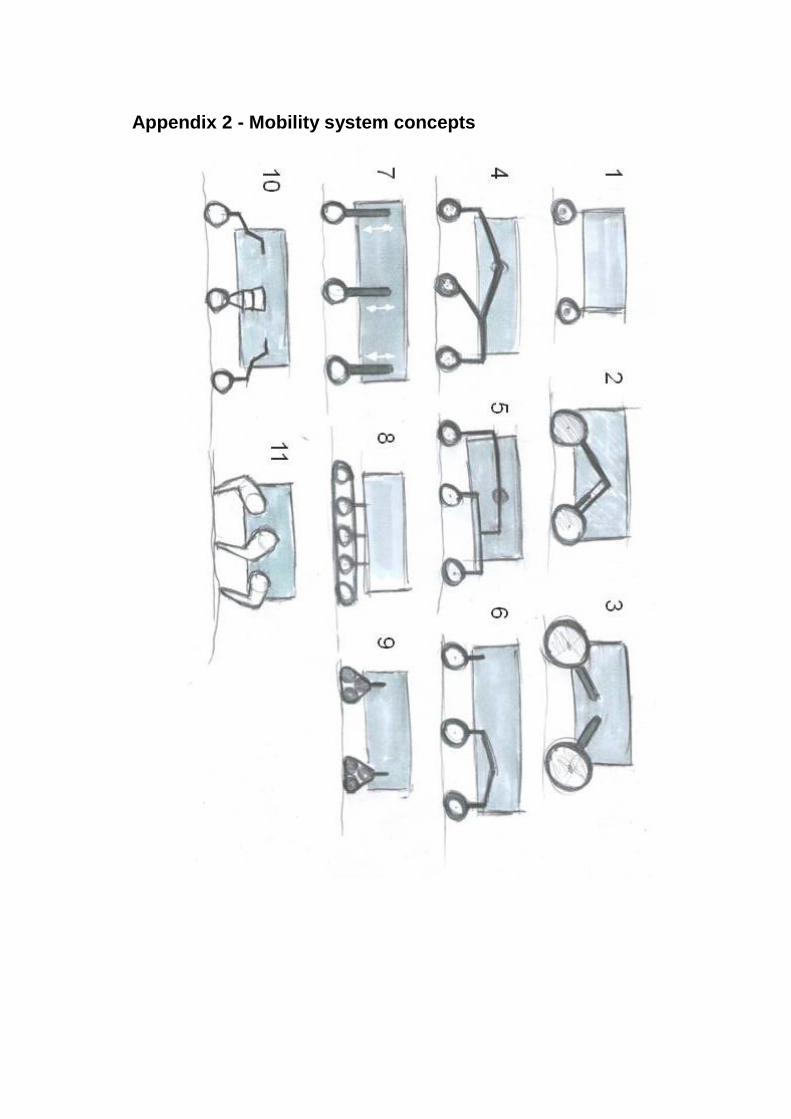
Appendix 2 - Mobility system concepts

Appendix 3 - Rocker-bogie suspension concept

Appendix 4 - Gantt chart

Appendix 5 - Complete rover rendering

HALMSTAD UNIVERSITY • PO Box 823 • SE-301 18 Halmstad, Sweden • www.hh.se