Exam Review - Utah Review Acronyms ... System Monitoring To Ensure Drinking Water is safe monitor...
17
1 Operation and Maintenance Exam Review Acronyms GPM= gallons per minute MGD= million gallons per day TTHM= total trihalomethane PSI= pounds per square inch NTU= Nephelometric Turbidity Unit mg/L= milligrams per litre or ppm= parts per million are the same TON= Threshold Odor Number for odor in the water. Should be conducted at 60 degrees C System Monitoring To Ensure Drinking Water is safe monitor for: Bacteria Turbidity Chlorine residual Sample Bottles Sampling bottle/bag should be filled just above the fill line or about one inch from top. Bottles need to be sterilized by the lab & ready for use Bottles have Sodium Thiosulfate in them to neutralize the chlorine Bacteriological Sampling Procedures Should allow sample tap water to run several minutes or as long as necessary to clear service line Results are meaningless if sample is contaminated Sample identification cards need to filled out completely Red water could indicate bacteria or an electro-chemical phenomenon Bacteriological Sampling Procedures If sample is OK, this only indicates that water was safe at point of sample. Coliform is an indicator of bacteria presence, absence of coliform indicates water is safe Sample should be transported as soon as possible in a cool container with ice pack. Routine bactis should be taken at the customer’s tap at various points that represent the entire system Chain of custody forms need to be filled out completely Not smooth nosed
Transcript of Exam Review - Utah Review Acronyms ... System Monitoring To Ensure Drinking Water is safe monitor...

1
Operation and Maintenance
Exam Review
Acronyms� GPM= gallons per minute
� MGD= million gallons per day
� TTHM= total trihalomethane
� PSI= pounds per square inch
� NTU= Nephelometric Turbidity Unit
� mg/L= milligrams per litre or ppm= parts per million are the same
� TON= Threshold Odor Number for odor in the water. Should be conducted at 60 degrees C
System Monitoring
To Ensure Drinking Water is safe monitor for:
� Bacteria
� Turbidity
� Chlorine residual
Sample Bottles
� Sampling bottle/bag should be filled just above the fill line or about one inch from top.
� Bottles need to be sterilized by the lab & ready for use
� Bottles have Sodium Thiosulfate in them to neutralize the chlorine
Bacteriological SamplingProcedures
� Should allow sample tap water to run several minutes or as long as necessary to clear service line
� Results are meaningless if sample is contaminated
� Sample identification cards need to filled out completely
� Red water could indicate bacteriaor an electro-chemicalphenomenon
Bacteriological Sampling Procedures
� If sample is OK, this only indicates that water was safe at point of sample.
� Coliform is an indicator of bacteria presence, absence of coliform indicates water is safe
� Sample should be transported as soon as possible in a cool container with ice pack.
� Routine bactis should be taken at the customer’s tap at various points that represent the entire system
� Chain of custody forms need to be filled out completely
Not smooth nosed

2
Composite Sample
� A series of grab samplestaken from the same sampling point at different times and mixed together
� Grab samples represent instantaneous conditions at the time and location the sample was taken
Nitrates
� Fertilizing lawns and farms can cause elevated levels of nitrates
� Nitrates cause Methemoglobinemia known as “blue baby”syndrome
Nephelometric Turbidity Unit (NTU)
� The method used to
measure the cloudiness of
the water.
� The higher the NTU, the dirtier the water, the greater
the possibility of
microbiological contamination.
� Turbidity can mask bacteria
� The use of light through
water to measure
Particle Counter
� The method used to measure the cloudiness of the water – the amount of particles and the size of particles.
� The dirtier the water, the greater the possibility of microbiological contamination.
Weirs
� Measured from the crest of the weir to the horizontal water surface in the weir stilling basin
Membrane Filter Test
� Analyzes coliform bacteria colonies
� Any positive sample requires repeats
� More than one positive is a quality violation

3
GWR
� TC+ bacterial Samples
� Requires Triggered Source Water sample (TSW)
� All sources that were in operation at time of +TC sample
� You can email DDW on sources not sampled –not running
� Test for fecal coliform
GWR continued
� 5 additional samples if first Triggered Source Water sample is Fecal+
� 2 or more sourcesrequires you to submit new sample site plan
� Correct significant deficiencies within 120 days
New Minimum PSI Standards
� Water pressure is measured in psi
� Maintain minimum of 20 psi at all times
� 20 psi during fire flow
� 30 psi during peak instantaneous demand
� 40 psi during peak daydemand
Sanitary Surveys Performed By
� Executive Secretary shall ensure a sanitary survey is conducted at least every 3 years
� Division of Drinking Water
� DEQ District Engineers
� Local Health Departments
� Forest Service Engineers
� Utah Rural Water Association staff
� Consulting Engineers
� Others authorized by Executive Secretary
Aesthetics
� Means attractive or appealing.
� With respect to water it means taste, odor, or coloration of the water.
� Things that affect this are extreme hardness or high total dissolved solids
� Effects range from bad smell and poor taste to causing stains on laundry and/or fixtures
� Hydrogen sulfide causes rotten egg odors
Water Storage Reservoirs
� Provides adequate water to the water system during average and peak demands
� Provides adequate pressuresthroughout the water systems
� Must be covered to prevent algae and bacterial growth
� Reserve storage
� Fire protection
� Most susceptible to degradation from external sources
Measured as volume

4
Screen Sizes
� #14 mesh for air vents and air vacuum release valve
� Air vac vent pipe above the flood line
� #4 mesh for overflow and drain lines
� #14 mesh = 14 squares per inch
� #4 mesh = 4 squares per inch
#14
#4
Pressure Tanks
� Blow off valves should be able to discharge at pumping rate
� Frequent on & off cycling of the booster pumpshows lack of air in tank & is water logged
Blow off
Reservoir Maintenance
� Comprehensive inspections and cleaning inside of tank should be done every 3 to 5 years or more frequently
� Repair
� Disinfect
� Take bacti’s
� Inspect Vents- for ice, screen holes, etc.
� Long & short life coatings for tank interiors
Surface Reservoirs
� Most significant reason for turn over is a change in surface water temperature and density
� Act as pre-sedimentation basins
� Water is most dense at 39.2 deg F, 4 deg C.
� Colder water has more oxygen
SCBA
� Self Contained Breathing Apparatus
� Always use when around gas leaks & oxygen deficient areas
Confined Spaces
� Reservoir site entry
� Sources- where chemicals are stored
� Vehicles- Keep away from manhole
� Vaults- Carbon Monoxide (CO) will settle to the floor.
� Minimum oxygen level of 19.5%

5
Chemical Handling
� All chemicals should be stored according to the manufacturer’sspecs
� Chemical compound has multiple chemicals such as calcium carbonate
Tank Maintenance
� Cycling of water (movement)to prevent freezing
� Cathodic protection to protect from corrosion
� Age of the water in the tank attributed to quality problems cause by low demand or short circuiting
� Sandblasting is recommended for preparing interior of tank
� Should be sampled for possible water quality changes
Disinfection of Reservoirs
� Facility disinfected before it is put on line
� Disinfected after cleaning, repair, painting
� AWWA C652
� Full reservoir – 10 mg/l/ 24 hours
� 6 hour/24 hour
� Spraying interior – 200 mg/l – 30 minute detention time
� Fill 5 %/ 50 ppm – 6 hours, then fill rest of tank <2 ppm – 24 hours
� At least one bacteriological sample(TC-)
Water Distribution Systems� Leaks get worse� Do a water audit to identify water &
revenue losses� Leak surveys should be done during low
flows� Cracked mains should be replaced
� Pressures can be measured at a fire hydrant or pressure regulating station
� Distribution system pressures� 20 psi at all times for peak instantaneous flows
� Minimum Water main size� 8 inch with fire hydrants
� Unless you have an engineer signature to buy off on it
� 4 inch without fire hydrants
Distribution Systems
� Water mains
� 10 Feet horizontal distance from sewer main
� Water main and sewer mains must cross at least 18” of separation
� Water line is on top
� Water & sewer not installed in the same trench.
� Anaerobic growth develops in water devoid of oxygen causing odor problems
� Hydraulic adequacy determined by pressure measurements throughout system at various times
� Looped to prevent dead ends, quality problems, and better flow
Customer Service Connection
� Corporation valve (corp stop) for customer service line shut off
� ¾” most common customer service connection
� Thaw service line with hot water or warm air
� Consider flow rate & pressure for sizing

6
New Main Installation
� Jacking and Boring is the most common technique for the construction of a pipeline under a heavily traveled highway or railway without disrupting the traffic
New Water Mains
� Steps taken to put into service� Pressure and leak test� Flush out debris� Keep pipe clean� Disinfect the pipe – AWWA C651� Take a chlorine residual� Flush highly chlorinated water� Bacteriological Samples –
� 2 samples taken 24 hours apart. Why?
� Special conditions
� Keep ends of pipe plugged when unmanned
Pressure Testing New Water Main
� Should be done at 50% higher than normal operating pressure or 150 psi whichever is larger
� Duration 4 Hours
� New connections installed under pressure are calledhot taps
Water Mains
� Never shut main valve completely (may cause a back siphon)
� Disinfect with tablets or granular @ 25 mg/L for 24 hours
� Continuous Feed – 10 mg/L after 24 hours
� Fill main with water
� Flush out debris
� Fill with chlorinated water
Backfilling Mains
� Notify other utilities or blue stakes before digging
� Soil placed equally on both sides half way up of the pipe in layers hand tamped
� Pipe should covered by about 12” of soil
� “Well Point” used to dewater trenches
� Shallow mains more susceptible to freezing
Thrust Blocking
� Thrust Block - a concrete mass cast in place between a fitting and the undisturbed soil at the side or bottom of the pipe trench.
� Purpose is to keep fittings from moving & either coming loose or apart from the force of the water pressure in the pipe.
� Thrust anchors – used when thrust blocks cannot be used
� Restrained fitting – use of clamps or anchor screws on fittings
� Tie rods – used on mechanical joint fittings that a located close together
� Block should be centered on thrust force
7
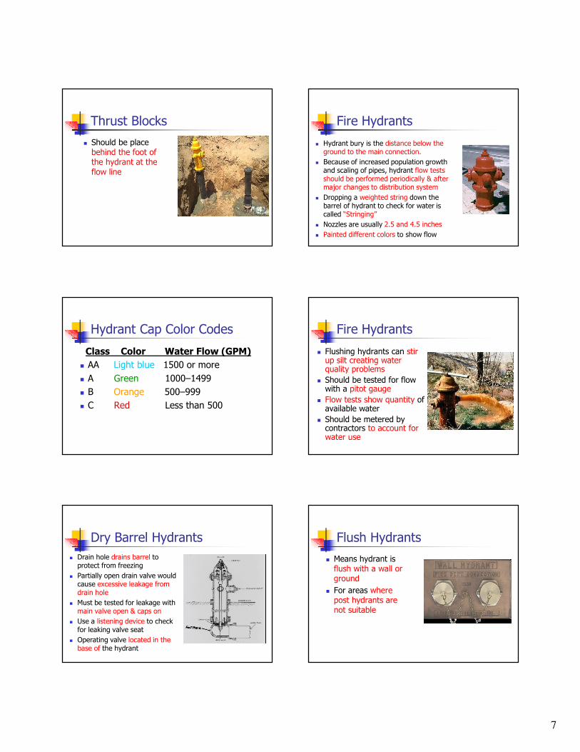
Thrust Blocks
� Should be place behind the foot of the hydrant at the flow line
Fire Hydrants
� Hydrant bury is the distance below the ground to the main connection.
� Because of increased population growth and scaling of pipes, hydrant flow tests should be performed periodically & after major changes to distribution system
� Dropping a weighted string down the barrel of hydrant to check for water is called “Stringing”
� Nozzles are usually 2.5 and 4.5 inches
� Painted different colors to show flow
Hydrant Cap Color Codes
Class Color Water Flow (GPM)
� AA Light blue 1500 or more
� A Green 1000–1499
� B Orange 500–999
� C Red Less than 500
Fire Hydrants
� Flushing hydrants can stir up silt creating water quality problems
� Should be tested for flow with a pitot gauge
� Flow tests show quantity of available water
� Should be metered by contractors to account for water use
Dry Barrel Hydrants
� Drain hole drains barrel to protect from freezing
� Partially open drain valve would cause excessive leakage from drain hole
� Must be tested for leakage withmain valve open & caps on
� Use a listening device to check for leaking valve seat
� Operating valve located in the base of the hydrant
Flush Hydrants
� Means hydrant is flush with a wall or ground
� For areas where post hydrants are not suitable

8
Flushing the System
� Dead End Systems
� Water Quality Issues
� Customer Complaints
� Be mindful of environmental concerns
� During periods of low demand
Flushing Procedure
� Notify customers thru billing, newspaper, or electronic media of times and places affected or anything affecting the condition of their water
� Explain Intent Of Flushing
� Notify Hospitals, Dialysis Patients, Restaurants, Laundromats, & Others That May Be Affected
Flushing The System
� When The System Has Become Contaminated
� Newly Installed Or Repaired Mainlines
Flushing Hydrants
� Helps remove taste & odor causing deposits
� Helps remove encrustations that may restrict flow
� Helps remove sand, rust, & biological materials that cause water quality problems
FLUSHING PROCEDURE
� Try To Avoid Flooding Traffic Areas
� Open Hydrant Fully For 5 To 10 Minutes To Stir Up Deposits
� Don’t let nearby areas drop below 20 psi to avoid negative pressures
� Record Pertinent Data: Odor, Water Appearance, Times, & Places, Etc.
Fire Fighters
� Fire fighters can createnegative pressures
� Dead end systems would likely haveinadequate flows for firemen

9
Valves
� All system valves should be exercised annually
� Purpose is to isolatesections of the system
Gate Valves
� Most commonly used valve in distribution system
� Gate Valve: Isolation only, should be either all the way open or all the way closed
� Cavitation (formation & collapse of bubbles) can occur
� Fully open has least amount of head loss from other valves
� Can be repacked without taking out of service
Globe Valves
� Best for flow control throttling, & pressure regulating
Butterfly Valves -
� Higher resistance to flow
� Operates easily & quickly
� They cost less than gate valves
� Used for flow control & isolation
Ball & Plug Valves Sluice Gate & Sleeve Valves

10
PRV Valves
� Pressure Sustaining/Reducing: maintain either upstream or downstream pressures depending on the position of the pilot screw.
� Need to be maintained periodically
� Help reduce water hammer
Pressure Reducing Valves
� Installed in parallel to handle high & low flows
Altitude Valve
� A good valve to regulate tank levels
� Altitude valve: opens when system psi drops below a certain pressure and closes when the reservoir reaches a predetermined level.
Pump Control Valves
� Allow pumps to be started & stopped against a closed valve
� Best method to control water hammer
Check Valves
� Keep flows going one direction
� Flow must be directional with pump discharge lines, customer service lines, and water treatment plants
Air Release Valves (air-vacs)
� Allow air in & out
� Should be placed athigh points in the system
� Need to be screened & protected from flooding
� Relief valve outlet12” above ground

11
Water Hammer
� Occurs when a valve is closed quickly or pump shuts down and causes the water pressures to rise and fall rapidly.
� Sounds like some hammering on pipe.
� Can damage pipes, causing them burst.
System Mapping
� Accurate mapping ensures the operators can locate the valvesand main lines in case of a main break or leak
pH� pH: expression that refers to the basic or acidic conditions of the water
� pH is measured on a scale from 0 to 14.
� Less than 7 is more acidic, greater than 7 is more basic or higher alkalinity 7 is neutral.
pH
� pH and alkalinity tests can be performed to assess the corrosiveness of the water
� Alkalinity expressed as Calcium Carbonate
� Chlorine lowers the pH & chlorine rate may need to be increased
Water Hardness
� Caused mainly by salts of calcium and magnesium, such as bicarbonate, carbonate, sulfate, chloride and nitrate.
� Causes formation of soap curds
� Deposits show chemical instability
� Deposits of scale in boilers & fixtures
� Damages in some industrial processes
� Objectionable tastes in water
12
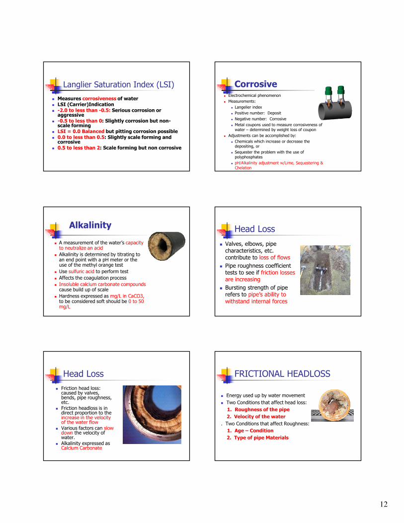
Langlier Saturation Index (LSI)
� Measures corrosiveness of water� LSI (Carrier)Indication� -2.0 to less than -0.5: Serious corrosion or aggressive
� -0.5 to less than 0: Slightly corrosion but non-scale forming
� LSI = 0.0 Balanced but pitting corrosion possible� 0.0 to less than 0.5: Slightly scale forming and corrosive
� 0.5 to less than 2: Scale forming but non corrosive
Corrosive� Electrochemical phenomenon
� Measurements:
� Langelier index
� Positive number: Deposit
� Negative number: Corrosive
� Metal coupons used to measure corrosiveness of
water – determined by weight loss of coupon
� Adjustments can be accomplished by:
� Chemicals which increase or decrease the depositing, or
� Sequester the problem with the use of
polyphosphates
� pH/Alkalinity adjustment w/Lime, Sequestering &
Chelation
Alkalinity
� A measurement of the water’s capacity to neutralize an acid
� Alkalinity is determined by titrating to an end point with a pH meter or the use of the methyl orange test
� Use sulfuric acid to perform test
� Affects the coagulation process
� Insoluble calcium carbonate compoundscause build up of scale
� Hardness expressed as mg/L in CaCO3, to be considered soft should be 0 to 50 mg/L
Head Loss
� Valves, elbows, pipe characteristics, etc. contribute to loss of flows
� Pipe roughness coefficient tests to see if friction losses are increasing
� Bursting strength of pipe refers to pipe’s ability to withstand internal forces
Head Loss
� Friction head loss: caused by valves, bends, pipe roughness, etc.
� Friction headloss is in direct proportion to theincrease in the velocity of the water flow
� Various factors can slow down the velocity of water.
� Alkalinity expressed as Calcium Carbonate
FRICTIONAL HEADLOSS
� Energy used up by water movement
� Two Conditions that affect head loss:
1. Roughness of the pipe
2. Velocity of the water
. Two Conditions that affect Roughness:
1. Age – Condition
2. Type of pipe Materials

13
C-Factor
� Indicates the smoothness pipe material
� The higher the C value, the smoother the pipe.
� To calculate measure flow, pipe diameter, distance between two pressure gauges, and the friction losses between the gauges.
� 3 most common types of plastic pipe are PVC, PE, & ABS
� PVC least susceptible to corrosion
� C value reduced by tuberculation
PVC has higher C- factor than concrete
Water Loss
� Affected by: leaks, pressures, efficiency of the meter maintenance, attention given to leak reduction & unauthorized use of water
� Some systems 10% of the water produced
� Other systems not until 20%
Consumer Calls
� Persons name, address, & phone
� What’s the problem: taste, odor, discolor,etc.
� When was problem first noticed?
� Duration of problem?
� Are neighbors having same problems?
� Has it resulted in any illness?
� Has Local Health Dept. or DDW been notified?
� Can they get a sample in a clean glass?
Cross Connections
� Determined by the degree of hazard� Cross connection: a connection between a potable and an
unapproved source.� Two Types of Backflow:
Backsiphonage: backflow caused by a negative or below atmospheric pressure in a water system.
Backpressure: when users pressure is higher than the system pressure
� Water user is responsible to keep contaminants out of the water system
� Flush out debris and trapped air in newly installed assemblies
� An effective program helps minimize degradation of the water system
� Responsible for most waterborne disease outbreaks
Devices and Assemblies
� Keep contaminants out� Air Gap: a physical break between to connections. Minimum of 1” or two times the diameter of the pipe & safest method of backflow prevention
� Double Check Assembly: Has two independent internally loaded check valves, 2 shut off valves, & 4 test cocks.
Cross Connections
� Reduced Pressure Principle Assembly: For High Hazards, has 2 spring loaded check valves, a relief valve, 4 test cocks, and 2 shut off valves. Relief port can’t be submerged & installed 12” above floor
� Pressure Vacuum Breaker: internal check valve, an internal loaded air poppet, 2 shut off valves and 2 test cocks. Not designed for back pressure

14
Cross Connection
� Atmospheric Vacuum Breakers not designed to protect against back pressure
� Prior to the installation of any backflow prevention assembly or device owner should be advised thermal expansion hazards
Wire to Water Efficiency
� The combined efficiency of the pump and the motor together. Also called the over all efficiency.
� Water HP/Electrical HPx100%=over all efficiency
� The amount of energy required to overcome the inefficiencies of the pump and motor
Electric Motors� Upon start up an electric motor will
develop a torque to turn the pump shaft and impeller
� Torque causes motor to draw a high amperage
� Amperage drops once the pump is up to speed.
� To change rotation on 3 phase, switch any 2 leads
� Transformers step down voltage
� Circuit breakers protect from circuit overloads
Digital Multimeters
� Ohm meters measure resistance
� Volt meters measure voltage
� Amp meters measure current
� Tachometer would showpump speed
� Setting should be set to next highest level of what you measuring
Lightning Arrestor
� Becomes a low resistance conductor to ground when the line voltage exceeds a predetermined amount
� Used to protect equipment from lightning strikes.
� No device made to protect against a direct hit.
Power Sources
� Primary Sources- Power Company
� Auxiliary Sources-Diesel, Natural Gas, & Gasoline Powered Generators may be necessary in an emergency

15
Meter Sizing Considerations
� Pressure at the service connection
� Highest fixture in the building being
served
� Any back flow prevention device
� A 5/8 inch meter should be tested every 5 to 10 years.
� Meter should not have more than
20 psi of head loss.
� One inch and smaller meters
shouldn’t exceed 15 psi of head loss
Small Meter Installation
� Meter pit located on public property
� Meter pit relatively safe from vehicle & snow removalequipment
� Riser pipes should be 1 to 2 inches away from meter box walls
� Use of meter yoke� Use jumper cable to protect from electrical shock from piping in the home
Meter Accuracy
� Measure water flow� Worn meters will cause the meter to under register, allowing the customer to receive more water than they pay for.
� Unaccountable water loss is the term used in determining meter accuracy & leakage
� Over time a worn meter will cost the water system revenue.
� Formula: Meter Accuracy= (Meter,GPM)(100%)/Volume,GPM
Magnetic Meters
� Maintenance calibration should include flow at zero flow rate
Compound Meters
� For low to intermediate flows
� Occasionally high flows
Positive Displacement Meter
� Nutating disk: nutating means nodding. When the water flows the disk rotates.

16
Oscillating Piston Meter
� Displacement type
� Water flows into a chamber and displaces piston
� Oscillating circular motion moves meter
� Higher head loss than nutating disk
Velocity Meter & Venturi
� Mechanical rotors or propellers are turned by velocity of water to measure flow
� Venturi meters measure differential pressure & have no moving parts.
� Venturi meters are best forproviding uninterrupted flow
Velocity Meter
Iron
� Consumer complaints
� Can cause stains on laundry & fixtures
� Formation of iron bacteria that form slick slimes on pipe walls
� Taste and odor problems
� Reacts with chlorine increasing use
� Can be removed thru aeration, flushing & polyphosphates
� Mixed with manganese react withdissolved oxygen forming insoluble compounds
Manganese
� Iron mixed with manganese reacts with dissolved oxygen forming insoluble compounds
� Causes black stains
Electrolysis
� Decomposition of material by an outside electriccurrent
� Electric current caused bymovement of water in the line
� Cathodic protection installed to preventcorrosion
� Magnesium anodes help prevent galvanic corrosion
� Galvanic corrosion caused by connecting dissimilar metals
� Metal coupons evaluated for weigh loss
Tanks – Cathodic Protection
Anodes

17
Ground Water
� Water passing thru porous soil is called percolation
� Water bearing geological formation is called an aquifer
Wells
� Sanitary seal – prevents contamination from entering
� Well casing – pipe placed inside well to keep it open
� Grout – mixture of cement, water and sand pumped between the casing & the drilling hole (annulus)
� Specific capacity is the well yield in GPM per foot of drawdown
Well Maintenance
� Water needs to be pumped to waste until it clears up
ACCURATE RECORD KEEPING
� Shows decreases in flow and pressures
� Insures each piece of equipment receives proper attention to prolong its life
� Shows when preventive maintenance or repairs were last performed
� Reduces liability to operator & improves customer service
� Work orders best way to track system maintenance
The end
� Contact Information
� Kim Dyches
� 801-536-4202