
Exam 1 Tue. Sep. 29, 5:30-7 pm, 145 Birge
30
1 Exam 1 Tue. Sep. 29, 5:30-7 pm, 145 Birge Covers 21.5-7, 22, 23.1-4, 23.7, 24.1-5, 26 + lecture, lab, discussion, HW 8 1/2 x 11 handwritten note sheet (both sides) allowed Chap 21.5-7, 22 Waves, interference, and diffraction Chap 23 Reflection, refraction, and image formation Chap 24 Optical instruments Chap 26 Electric charges and forces
-
Upload
matthew-schultz -
Category
Documents
-
view
30 -
download
0
description
Covers 21.5-7, 22, 23.1-4, 23.7, 24.1-5, 26 + lecture, lab, discussion, HW. Exam 1 Tue. Sep. 29, 5:30-7 pm, 145 Birge. Chap 21.5-7, 22 Waves, interference, and diffraction Chap 23 Reflection, refraction, and image formation Chap 24 Optical instruments Chap 26 - PowerPoint PPT Presentation
Transcript of Exam 1 Tue. Sep. 29, 5:30-7 pm, 145 Birge

1
Exam 1 Tue. Sep. 29, 5:30-7 pm, 145 Birge
Covers 21.5-7, 22, 23.1-4, 23.7, 24.1-5, 26 + lecture, lab, discussion, HW
8 1/2 x 11 handwritten note sheet (both sides) allowed
Chap 21.5-7, 22 Waves, interference, and diffraction
Chap 23 Reflection, refraction, and image formation
Chap 24 Optical instruments
Chap 26 Electric charges and forces

2
Properties of waves
Wavelength, frequency, propagation speed related as
Phase relation In-phase: crests line up 180˚ Out-of-phase: crests line up with trough Time-delay leads to phase difference Path-length difference leads to phase difference
€
λf = v

3
QuestionTwo waves of wavelength λ are traveling through a medium with index
of refraction n=1. One of the waves passes a medium of thickness d=λ and index n=1.25..
What is the phase difference between the waves far to the right?
A. λ/4
B. λ/2
C. λ
D. 2λ
n=1 λ
n=1.25

4
Ch 22, 21.5-7: Waves & interference
Path length difference and phase different path length -> phase difference.
Two slit interference Alternating max and min due to path-length difference
Phase change on reflection π phase change when reflecting from medium with higher index of
refraction
Interference in thin films Different path lengths + reflection phase change

5
Phase difference & interference
Path length difference d Phase difference = d(2π /λ) radians Constructive for 2πn phase difference
L
Shorter path
Longer path
Light beam
Foil with two narrow slits
Recording plate

6
QuestionYou are listening to your favorite radio station, WOLX 94.9 FM (94.9x10⁶ Hz)
while jogging away from a reflecting wall, when the signal fades out. About how far must you jog to have the signal full strength again? (assume no phase change when the signal reflects from the wall)
A. 3 m
B. 1.6 m
C. 0.8 m
D. 0.5 m
d
xd-x
path length diff = (d+x)-(d-x)= 2x
λ=3.16 mHint: wavelength = (3x10⁸ m/s)/94.9x106 Hz
Destructive 2x=λ/2x=λ/4Constructive make 2x=λx=λ/2
x increases by λ/4 = 3.16m/4=0.79m

7
Two-slit interference

8
Two-slit interference: path length
y
L
€
≈d sinθ ≈ d y /L( )Path length difference
€
≈2πd sinθ
λ≈
2π d
λy /L( )Phase difference
Constructive int:
Destructive int.
Phase diff = Path length diff =
Phase diff = Path length diff =
€
mλ , m = 0,±1,±2K
€
2πm, m = 0,±1,±2K
€
2π (m +1/2), m = 0,±1,±2K
€
(m +1/2)λ , m = 0,±1,±2K

9
Reflection phase shift
Possible additional phase shift on reflection. Start in medium with n1,
reflect from medium with n2
n2>n1, 1/2 wavelength phase shift
n2<n1, no phase shift
Difference in phase shift between different paths is important.

10
Thin film interference
air: n1=1
n2>1
1/2 wavelength phase shiftfrom top surface reflection
t
λair
λair/n
Extra path lengthExtra path length needed for constructive interference is
No phase shift frombottom interface
€
m +1/2( ) λ air /n( )
€
⇒ 2t = m +1/2( ) λ air /n( )
air: n1=1
Reflecting from n2
Reflecting from n1

11
Thin-film interference example
Coated glass in air, coating thickness = 275nm
Incident white light 400-700nm Glass infinitely thick What color reflected light do you see? Both paths have 180˚ phase shifts So only path length difference is
important
nfilm=1.2
nglass=1.5
nair=1Incident light
eye
t=275nm
€
2t = mλ air /n film
€
m =1⇒ λ = 660nm

12
Thin Film Interference II Same coated glass
underwater Now only one path has
180˚ phase shift
nfilm=1.2
nair=1
Incident light
eye
nglass=1.5
nwater=1.33
€
2t = m+1/ 2( )λair / nfilm
€
λair = 2tn film / m +1/2( )
= 2 275nm( ) 1.2( ) / m +1/2( )
m=0 gives 1320 nm, too long.
m=1 gives 440 nm
Color changes underwater!

13
Diffraction from a slit
Each point inside slit acts as a source
Net result is series of minima and maxima
Similar to two-slit interference.
Angular locations of
minima (destructive interference)

14
Overlapping diffraction patterns Two independent point
sources will produce two diffraction patterns.
If diffraction patterns overlap too much, resolution is lost.
Image to right shows two sources clearly resolved.
Angularseparation
Circular aperture diffraction limited:
€
min =1.22λ
D
15
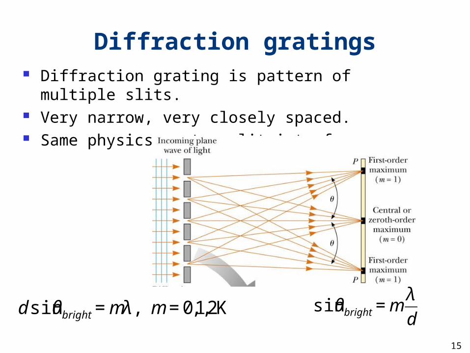
Diffraction gratings Diffraction grating is pattern of multiple slits. Very narrow, very closely spaced. Same physics as two-slit interference
€
d sinθbright = mλ , m = 0,1,2K
€
sinθbright = mλ
d

16
Chap. 23-24: Refraction & Ray optics
Refraction Ray tracing
Can locate image by following specific rays Types of images
Real image: project onto screen Virtual image: image with another lens
Lens equation Relates image distance, object distance, focal length
Magnification Ratio of images size to object size

17
Refraction Occurs when light moves into medium with different
index of refraction. Light direction bends according to
i,1 r
2
Angle of refraction
n1
n2
€
n1 sinθ1 = n2 sinθ2
Special case:Total internal reflection

18
Total internal reflectionTotal internal reflection occurs
A) at angles of incidence greater than that for which the angle of refraction = 90˚
B) at angles of incidence less than that for which the angle of refraction = 90˚
C) at angles of incidence equal to 90˚
D) when the refractive indices of the two media are matched
D) none of the above

19
1) Rays parallel to principal axis pass through focal point.2) Rays through center of lens are not refracted.
3) Rays through F emerge parallel to principal axis.
Lenses: focusing by refraction
F
F
Object
ImageP.A.
Here image is real, inverted, enlarged

20
Different object positions
Image (real, inverted)
Image (real, inverted)Object
Image (virtual, upright)
These rays seem to originatefrom tip of a ‘virtual’ arrow.
21
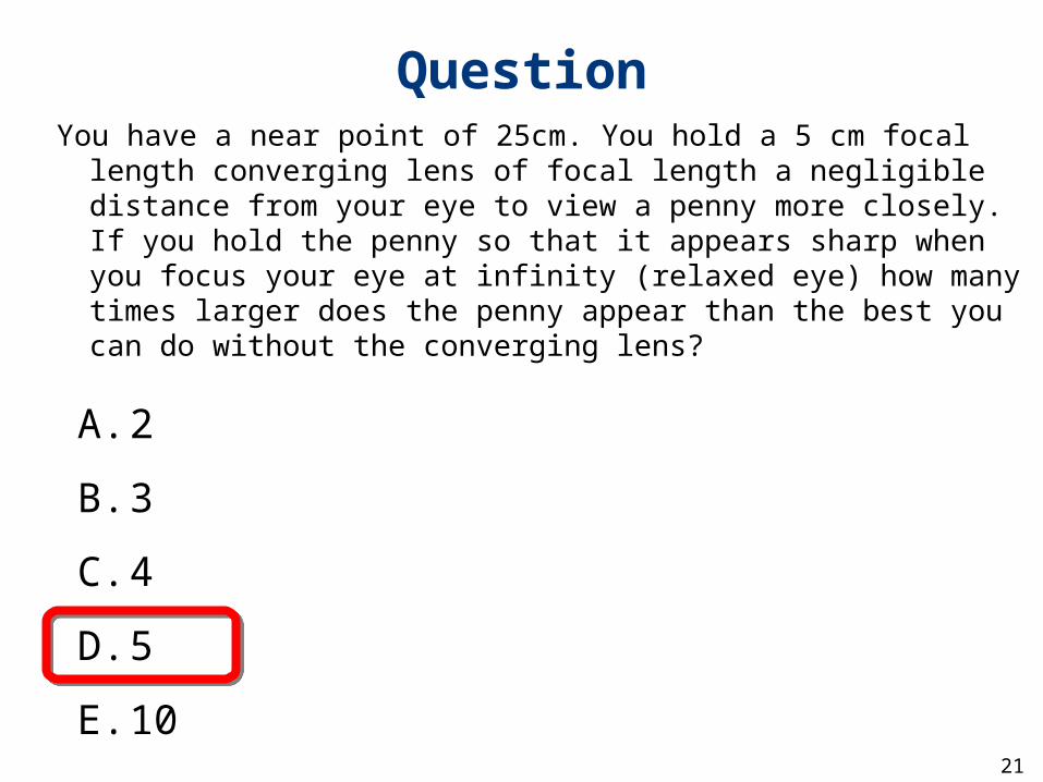
QuestionYou have a near point of 25cm. You hold a 5 cm focal length
converging lens of focal length a negligible distance from your eye to view a penny more closely. If you hold the penny so that it appears sharp when you focus your eye at infinity (relaxed eye) how many times larger does the penny appear than the best you can do without the converging lens?
A. 2
B. 3
C. 4
D. 5
E. 10

22
Equations
Magnification = M =
Image and object different sizes
Image (real, inverted)
s s’
€
−image height
object height= −
′ s
s= −
image distance
object distance€
1
s+
1′ s =
1
fRelation between
image distanceobject distancefocal length

23
Question
You want an image on a screen to be ten times larger than your object, and the screen is 2 m away. About what focal length lens do you need?
€
1
s+
1′ s =
1
fA. f~0.1m
B. f~0.2m
C. f~0.5m
D. f~1.0m
s’=2 m
mag=10 -> s’=10s ->s=0.2m
€
1
0.2m+
1
2m= 5.5 =
1
f⇒ f = 0.18m
Thurs. Sep. 17, 2009 Physics 208, Lecture 524
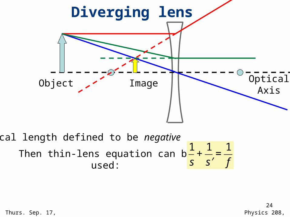
Diverging lens
OpticalAxis
Then thin-lens equation can be used:
€
1
s+
1′ s
=1
f
Object Image
Focal length defined to be negative

Mon. Feb. 4, 2008 Physics 208, Lecture 4 25
Virtual image ‘Object’
Eyepiece
CompoundMicroscope
qp
Object Real, inverted, image
Eyepiece: simple magnifier.
Angular Mag.=25cm/p
~25cm/feyepiece
Objective lateral mag.
=-q/p~L/fobjective
Objective

26
Chapter 26: Electric Charges & Forces
Triboelectric effect: transfer charge Total charge is conserved
Vector forces between charges Add by superposition Drops off with distance as 1/r2
Insulators and conductors Polarization of insulators, conductors

27
Electric force: magnitude & direction
Electrical force between two stationary charged particles
The SI unit of charge is the coulomb (C ), µC = 10-6 C 1 C corresponds to 6.24 x 10¹⁸ electrons or protons
ke = Coulomb constant ≈ 9 x 10⁹ N.m2/C2 = 1/(4πo) o permittivity of free space = 8.854 x 10⁻¹² C2 / N.m2
Directed along line joining particles.

28
+ -
-
Equal but opposite charges are placed near a negative charge as shown.
What direction is the net force on the negative charge?
A) Left
B) Right
C) Up
D) Down
E) Zero
221
rqkq
F =
Forces add by superposition

The electric dipole
Dipole moment
Vector
Points from - charge to + charge
Has magnitude qs
€
rp
Can all be approximated by electric dipole.
Two opposite charges magnitude q separated by distance s

Force on an electric dipole• What is the direction of the force on the electric
dipole from the positive point charge?
€
rp
+
A. Up
B. Down
C. Left
D. Right
E. Force is zero
How does the magnitude of the force depend on ?
€
rp


![Punit Pandey - hindilok.com · tUe okj] tUe frfFk] tUe u{k=] tUe ;ksx rFkk tUe dj.k bu ik¡pksa dks feykdj iapkax Qy dh x.kuk dh xbZ gSA tUe ds le; mijksä lHkh ik¡pksa dkjdksa dks](https://static.fdocuments.in/doc/165x107/5e075a9967b7f075a46f6112/punit-pandey-tue-okj-tue-frffk-tue-uk-tue-ksx-rfkk-tue-djk-bu-ikpksa.jpg)