EX2N-30A Programmable Text Monitor User Manual Isolation...
2
Thank you for choosing Coolmay programmable text monitor. This manual mainly explains the features、general specifications and wiring methods of programmable text monitor. Detailed programming for PLC please refers to < COOLMAY PLC Programming Manual> and text refers to <EX2N-A Software User Manual> . Main features of programmable text monitor: 1. Highly intergrated。At most 24AI/20AO,12DI/8DO. For EX2N-30A, only one Rs485 can be added; for EX2N-40A/50A, 2 Rs485 ports or 1 Rs232 and 1 Rs485 can be added. 2. Support high-speed counting and high-speed pulse. High-speed counting can be added to at most 6 single-phase , 3 AB(Z) 10-100KHz. High-speed pulse can be added up to 4 or 520-200KHz. 3.Support special encryption for both HMI and PLC. Setting 12345678 as password of PLC can thoroughly prevent data from being read. 4.3.81MM pluggable terminals being adopted for easy wiring. 5.Mitsubishi programming software for PLC, 30A, 40A, 50A for text seperately Product Information Naming Rule Programmable Text Monitor User Manual diagram 1: Basic parameters ◆ Basic Specifications ◆ EX2N 1 2 3 4 5 6 7 40A 8 9 11 10 12 485/232 - 1P - 1C1 A0 V 2DA 4AD RT M 24 - - - - - - - 5A AC220V, DC24V 500mA DC24V 1500VAC 0-10V/0-20mA/0-5V -20°C~60°C 5%~95% RH -20°C~70°C Input ON Output OFF Filter Function Electric current of high-speed input is higher than 4.5mA Electric current of both is lower than 1.5mA With filter function, the filter time can be set among 0-100ms, defaulted as 10mA COM connected with negative pole Relay Output Index Max Current Load Voltage Circuit Insulation ON Respond Time Mechanical Life (without load) Electrical Life (Rated Load) Output Common Port Relay Mechanical Insulation About 10ms 10 million times 300k times COM connected with negative terminal Transistor Output Index Max Current Voltage of power supply Circuit Insulation Isolation voltage (external terminal) ON Respond Time Output Common Port Optocoupler Insulation COM connected with negative terminal Analog Input Index Input Signal Respond Time AI Quantity Accuracy Pt100 / PT1000 / Thermocouple / NTC / 0-10V / 0-20mA / 4-20mA, other signals can be customized. One scan cycle 0-12 channels 12bit, ±1% (full scale) Analog Output Index Output Signal AO Quantity Accurary 10 bit Interface COM Port Environment Working Temperature Relative Humidity Storage Temperature Vibrational Frequency 1 Rs232 programming port, Only one Rs485 port can be added in 30A; 2 Rs485 or 1 Rs232 and 1 Rs485 can be added in 40A/50A High-speed Counting 0-8 channels 10-57Hz, amplitude: 0.035mm; 57Hz-150Hz, accelerated speed: 4.9m/s² (10 times for directions XYZ,80 min. in total ) Common Port High-speed Output Frequency Electric current of common input is higher than 3.5mA Normally 2 single counting (X0/X3) or 2 AB phase counting (X0-X1/X3-X4) 10KHz. At most 6 single counting can be customized (4 100KHz、2 10KHz). Or 3 AB phase counting (2 100KHz、1 10KHz) or 3 ABZ counting (1 100KHz 、 2 5-10KHz) High-speed Output:10μs, others 0.5ms Y0/Y1/Y6/Y7 Normally 20Khz, at most 4-5 100-200KHZ Y10 can be added while 5 channels is customized. Installation Dimensions Mechanical Design Reference ◆ 1. Series EX2N 2. Text 30A:3.0" 40A:4.0" 50A:5.0" 3. I/O 10:5I/5O 16:8I/8O 24:12I/12O 4. Module M:Main module of universal controller 5. DO type: R: relay T: transistor RT: both relay and transistor 6. DI 4 channels for 30A, 12 channels for 40A/50A 7. DO 2 channels for 30A, 8 channels for 40A/50A 8. AI EK: Ek thermocouple PT:PT100 SR: S-type thermocouple A4:4-20mA A0:0-20mA JR: J-type thermocouple V:0-10V NTC: thermistor (10k/50k/100k) 9. AO V:0-10V A0:0-20mA V5:0-5V 10. C1stands for singe phase 100k high-speed counting, C2 for 100KHz AB phase counting C3 for 100KHz ABZ counting, C30 for 10Khz ABZ counting, at most 6 single phase 10Khz or 3 AB(Z) phase 10-100KHz can be custom-made. If 6 single phase 10KHz be made, the model should be 6C10. 11. P stand for 100KHz, P2 for 200KHz, 5P0 for 5 channel 20k. At most 4 100-200KHz can be customized for 30A, and 5 100-200KHz for 40A/50A 12. Optional COM port For EX2N-30A, only 1 Rs485 port can be added; for EX2N-40A/50A, 2 Rs485 ports or 1 Rs232 and 1RS485 can be added. AB Phase ABZ Phase Switching Value Analog (optional) High-speed counting (optional) High-speed pulse(optional) DI DO AI AO PLC Single Phase Output COM Port Programmable Text Monitor Models EX2N-30A/40A/50A-10M EX2N-30A/40A/50A-16M EX2N-30A/40A/50A-20M EX2N-30A/40A/50A-24M EX2N-40A/50A-30M EX2N-40A/50A-32M EX2N-40A/50A-36M EX2N-40A/50A-38M EX2N-40A/50A-40M EX2N-40A/50A-40M-S EX2N-40A/50A-44M 5 5 8 8 12 8 12 12 16 14 16 16 16 20 20 18 20 20 24 16 24 20 At most 4 channels can be added for 30A, 12 for 40A/50A At most 3ABZ can be added (1 10-100K , 2 5-10K) Normally 2-4 20K pulse output, at most 4 20-200K can be added in30A and 5 20-200K can be added in 40A/50A Note: only MT for 30A At most 2 channels for 30A, 8 channels for 40A/50A Only one Rs485 port can be added in 30A; 2 RS485 or 1 RS232 and 1 RS485 can be added in 40A/50A Normally 2 10K contained, at most 6 channels can be added ( 4 10-100K and 2 5-10K) Normally 2 10K contained, at most 3 AB can be added (2 10-100k and 1 5-10K) Diagram 1: Dimension Drawing EX2N-40A/50A Diagram 3:Cutout Size EX2N-30A Model Max Points Installation dimensionsOverall Size W*H*D(mm) A(mm) B(mm) EX2N-30A EX2N-40A EX2N-50A 24 points 44 points 44 points 119 194 194 93 138 138 134*102*30 212*148*40 212*148*40 Electrical design reference ◆ Product Structure EX2N-30A EX2N-40A EX2N-50A Diagram 2:Product Structure 6 9 1 8 12 3 2 7 10 11 4 5 1 3 1 4 1 3 1 4 6 1 3 1 4 1 4 10 11 12 2 7 3 1 4 10 11 12 9 8 5 2 7 3 Four installing holes in the side Termina block of power supply Terminal block of DO Terminal block of DI LCD backlight potentiometer POWER: POWER ON indicator ERR: light on when program errors occur RUN: light on when PLC is run Text/PLC programming port Optional RS232/485 PLC Run switch RUN/STOP AI AO RS485 LCD membrane panel 1 2 3 4 5 6 7 8 9 10 11 12 1 3 1 4 ◆ Hardware interface X13 X12 X10 X07 X06 X05 X04 X03 X02 X01 X00 COM Y13 Y12 Y10 Y07 Y06 Y05 Y04 Y03 Y02 Y01 Y00 COM DA1 DAD GND AD3 AD2 AD1 AD0 GND FG0V~24V Text/PLC programming port Optional RS232/485 PLC Run Switch Diagram 3 EX2N-30A Diagram 4 EX2N-40A/50A X23 X22 X21 X20 X17 X16 X15 X14 X13 X12 X10 COM X07 X06 X05 X04 X03 X02 X01 X00 COM Y21 Y20 Y17 Y16 Y15 Y14 COM3 Y13 Y12 Y10 COM2 Y07 Y06 Y05 Y04 COM1 Y03 Y02 Y01 Y00 COM0 X24 X25 X26 X27 AD07 AD06 AD05 AD04 AD03 AD02 AD01 AD00 GND GND DA00 DA01 DA02 DA03 A B Y22 Y23 A B 1 2 3 4 1 2 1 2 3 4 A:485+ B:485 - Diagram 6 Rs485 of PLC Diagram 5 COM1/COM2 Text/PLC programming port Pin Number Signal Description 2 3 TXD RXD Transmit Receive 5 Ground GND Optional RS485 of PLC (D8160) Text/PLC programming port 1 A 485+ 6 485- B 2 3 TXD RXD Transmit Receive 5 Ground GND Pin Number Signal Description Optional RS232 of PLC Optional Rs485 of PLC (D8120) 1 A 485+ 6 485- B 2 3 TXD RXD 5 GND Pin Number Signal Description Transmit Receive Ground Equivalent Circuit There is a power supply (DC24V) inside PLC to test switch state. The end user only need to put in the dry contact. The signal of OC output is needed if the output signal of active crystal sensor should be connected. Diagram 2: electrical parameters DC 24V Electrical Parameters Input Voltage Analog Input Index Isolation Mode Input Impedance Photocoupling High-speed input 3.3KΩ Common input 4.3Ω
Transcript of EX2N-30A Programmable Text Monitor User Manual Isolation...
Thank you for choosing Coolmay programmable text monitor. This manual mainly explains the features、general specifications and wiring methods of programmable text monitor. Detailedprogramming for PLC please refers to < COOLMAY PLC Programming Manual> and text refers to <EX2N-A Software User Manual> .
Main features of programmable text monitor:
1. Highly intergrated。At most 24AI/20AO,12DI/8DO. For EX2N-30A, only one Rs485 can
be added; for EX2N-40A/50A, 2 Rs485 ports or 1 Rs232 and 1 Rs485 can be added.
2. Support high-speed counting and high-speed pulse. High-speed counting can be added to at most 6 single-phase , 3 AB(Z) 10-100KHz. High-speed pulse can be added up to 4 or 520-200KHz. 3.Support special encryption for both HMI and PLC. Setting 12345678 as password of PLC can thoroughly prevent data from being read. 4.3.81MM pluggable terminals being adopted for easy wiring. 5.Mitsubishi programming software for PLC, 30A, 40A, 50A for text seperately
Product Information
Naming Rule
Programmable Text Monitor User Manual
diagram 1: Basic parameters
◆
Basic Specifications◆
EX2N1 2 3 4 5 6 7
40A8 9 1110 12
485/232-1P-1C1A0V2DA4ADRTM24 -------
5A
AC220V, DC24V
500mA
DC24V
1500VAC
0-10V/0-20mA/0-5V
-20°C~60°C
5%~95% RH
-20°C~70°C
Input ON
Output OFF
Filter Function
Electric current of high-speed inputis higher than 4.5mA
Electric current of both is lower than 1.5mA
With filter function, the filter time can be set among 0-100ms, defaulted as 10mA
COM connected with negative pole
Relay Output Index
Max Current
Load Voltage
Circuit Insulation
ON Respond Time
Mechanical Life (without load)
Electrical Life (Rated Load)
Output Common Port
Relay Mechanical Insulation
About 10ms
10 million times
300k times
COM connected with negative terminal
Transistor Output Index
Max Current
Voltage of power supply
Circuit Insulation
Isolation voltage(external terminal)
ON Respond Time
Output Common Port
Optocoupler Insulation
COM connected with negative terminal
Analog Input Index
Input Signal
Respond Time
AI Quantity
Accuracy
Pt100 / PT1000 / Thermocouple / NTC / 0-10V / 0-20mA / 4-20mA, other signals can be customized.
One scan cycle
0-12 channels
12bit, ±1% (full scale)
Analog Output Index
Output Signal
AO Quantity
Accurary 10 bit
Interface
COM Port
Environment
Working Temperature
Relative Humidity
Storage Temperature
Vibrational Frequency
1 Rs232 programming port, Only one Rs485 port can be added in 30A; 2 Rs485 or 1 Rs232 and 1 Rs485 can be added in 40A/50A
High-speed Counting
0-8 channels
10-57Hz, amplitude: 0.035mm; 57Hz-150Hz, accelerated speed: 4.9m/s²
(10 times for directions XYZ,80 min. in total )
Common Port
High-speed Output Frequency
Electric current of common input is higher than 3.5mA
Normally 2 single counting (X0/X3) or 2 AB phase counting (X0-X1/X3-X4) 10KHz.
At most 6 single counting can be customized (4 100KHz、2 10KHz).
Or 3 AB phase counting (2 100KHz、1 10KHz) or 3 ABZ counting (1 100KHz 、2 5-10KHz)
High-speed Output:10μs, others 0.5ms
Y0/Y1/Y6/Y7 Normally 20Khz, at most 4-5 100-200KHZ
Y10 can be added while 5 channels is customized.
Installation Dimensions
Mechanical Design Reference
◆
1. Series EX2N2. Text 30A:3.0" 40A:4.0" 50A:5.0"3. I/O 10:5I/5O 16:8I/8O 24:12I/12O4. Module M:Main module of universal controller5. DO type: R: relay T: transistor RT: both relay and transistor 6. DI 4 channels for 30A, 12 channels for 40A/50A7. DO 2 channels for 30A, 8 channels for 40A/50A8. AI EK: Ek thermocouple PT:PT100 SR: S-type thermocouple A4:4-20mA A0:0-20mA JR: J-type thermocouple V:0-10V NTC: thermistor (10k/50k/100k)9. AO V:0-10V A0:0-20mA V5:0-5V10. C1stands for singe phase 100k high-speed counting, C2 for 100KHz AB phase counting C3 for 100KHz ABZ counting, C30 for 10Khz ABZ counting, at most 6 single phase 10Khz or 3 AB(Z) phase 10-100KHz can be custom-made. If 6 single phase 10KHz be made, the model should be 6C10. 11. P stand for 100KHz, P2 for 200KHz, 5P0 for 5 channel 20k. At most 4 100-200KHz can be customized for 30A, and 5 100-200KHz for 40A/50A12. Optional COM port For EX2N-30A, only 1 Rs485 port can be added; for EX2N-40A/50A, 2 Rs485 ports or 1 Rs232 and 1RS485 can be added.
ABPhase
ABZPhase
Switching Value
Analog
(optional)
High-speed counting
(optional)
High-speed
pulse(optional)
DI DO AI AO PLC Single Phase
Output
COM PortProgrammable Text Monitor
Models
EX2N-30A/40A/50A-10M
EX2N-30A/40A/50A-16M
EX2N-30A/40A/50A-20M
EX2N-30A/40A/50A-24M
EX2N-40A/50A-30M
EX2N-40A/50A-32M
EX2N-40A/50A-36M
EX2N-40A/50A-38M
EX2N-40A/50A-40M
EX2N-40A/50A-40M-S
EX2N-40A/50A-44M
5 5
8 8
12 8
12 12
16 14
16 16
1620
20 18
20 20
24 16
24 20 At m
ost
4 c
hannels
can b
e a
dded for
30A,
12 for
40A/5
0A
At
mo
st 3
AB
Z c
an
be a
dd
ed
(1 1
0-1
00K
,
2 5
-10K
)
No
rmally 2
-4 2
0K
pu
lse o
utp
ut,
at
mo
st 4
20-2
00K
can
be a
dd
ed
in
30A
an
d 5
20-2
00K
can
be a
dd
ed
in
40A
/50A
Note: only MT for 30A
At
most
2 c
hannels
for
30A
, 8 c
hannels
for
40A
/50A
Only
one R
s485 p
ort
can b
e a
dded in
30A
; 2 R
S485 o
r 1 R
S232 a
nd 1
RS
485
can b
e a
dded in
40A
/50A
No
rmally 2
10K
co
nta
ined
, at
mo
st 6
ch
an
nels
can
be a
dd
ed
( 4
10-1
00K
an
d
2 5
-10K
)
No
rmally 2
10K
co
nta
ined
, at
mo
st 3
AB
can
be a
dd
ed
(2 1
0-1
00k a
nd
1 5
-10K
)
Diagram 1: Dimension Drawing
EX2N-40A/50A
Diagram 3:Cutout Size
EX2N-30A
Model Max PointsInstallation dimensionsOverall Size
W*H*D(mm)A(mm) B(mm)
EX2N-30A
EX2N-40A
EX2N-50A
24 points
44 points
44 points
119
194
194
93
138
138
134*102*30
212*148*40
212*148*40
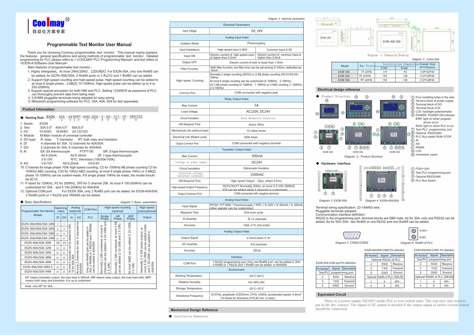
Electrical design reference
◆ Product Structure
EX2N-30A EX2N-40A EX2N-50A
Diagram 2:Product Structure
6
9
1
8
12
3
2 7
1011
4
5
13
14
13
14
613
14
1
4
10 11 12
2 7
3
1
4
10 11 12
98 52 7
3
Four installing holes in the side
Termina block of power supply
Terminal block of DO
Terminal block of DI
LCD backlight potentiometer
POWER: POWER ON indicator
ERR: light on when program
errors occur
RUN: light on when PLC is run
Text/PLC programming port
Optional RS232/485
PLC Run switch RUN/STOP
AI
AO
RS485
LCD
membrane panel
1
2
3
4
5
6
7
8
9
10
11
12
13
14
◆ Hardware interface
X13X12
X10X07X06X05X04X03X02X01X00COM
Y13Y12
Y10Y07Y06Y05Y04Y03Y02Y01Y00COM
DA1
DAD
GND
AD3
AD2
AD1
AD0
GND
FG0V~24V
Text/PLC programming port
Optional RS232/485
PLC Run Switch
Diagram 3 EX2N-30A Diagram 4 EX2N-40A/50A
X23X22X21X20X17X16X15X14X13X12
X10COMX07X06X05X04X03X02X01X00COM
Y21Y20Y17Y16Y15Y14COM3Y13Y12
Y10COM2Y07Y06Y05Y04COM1Y03Y02Y01Y00COM0
X24
X25
X26
X27
AD07
AD06
AD05
AD04
AD03
AD02
AD01
AD00
GND
GND
DA00
DA01
DA02
DA03
A B Y22
Y23
AB
1 2
3
4
1
2
1 2 3
4
A:485+
B:485 -
Diagram 6 Rs485 of PLCDiagram 5 COM1/COM2
Text/PLC programming port
Pin Number Signal Description
2
3 TXD
RXD
Transmit
Receive
5 GroundGND
Optional RS485 of PLC (D8160)
Text/PLC programming port
1 A 485+
6 485-B
2
3 TXD
RXD
Transmit
Receive
5 GroundGND
Pin Number Signal Description
Optional RS232 of PLC
Optional Rs485 of PLC (D8120)
1 A 485+
6 485-B
2
3 TXD
RXD
5 GND
Pin Number Signal Description
Transmit
Receive
Ground
Equivalent Circuit
There is a power supply (DC24V) inside PLC to test switch state. The end user only need toput in the dry contact. The signal of OC output is needed if the output signal of active crystal sensor should be connected.
Diagram 2: electrical parameters
DC 24V
Electrical Parameters
Input Voltage
Analog Input Index
Isolation Mode
Input Impedance
Photocoupling
High-speed input 3.3KΩ Common input 4.3Ω

Equivalent Circuit Inside PLC
COM0
Y0
Y1
Y2
Y3
COM1
Y4
Y5
1A
DC24V
1A
DC24V
Inside Logical Power Supply
Outp
ut D
rive
r C
ircu
it
Load
COM0
Y0
Y1
Y2Y3COM1
Y4
Y5
5A/1A
DC24V/AC220V
5A/1A
DC24V/AC220V
Outp
ut D
rive
r C
ircu
it
Load
Load
Load
Load
Load
Load
Load
Load
Load
Load
Load
Devices Distribution and Statement of Power-down Save
24VDC Power Supply
Equivalent Circuit Inside PLCInside Logical Working Power Supply
Diagram 7 Input Wiring
Diagram 8 Equivalent Circuit of Relay Output
5VDC Power Supply
Lo
gic
al C
ircu
it
Diagram 12 Analog Wiring
High-speed Counter 16bit Up Counter 32bit Up Counter
(0~20mA/0~10V)
AD
DA
GND
AD0
AD1
Ad11
GND
DA0
DA1
Da7
(0~20mA/4~20mA/0~10V)
104P
104P
104P
Analog input: AD0~AD11Analog output: DA0~DA7The negative terminals are connected with
GND of AI/AO separately.
Diagram 10 Inductive Load Absorbing Circuit
Please choose proper insurance for each load to avoid burning out the output unit and the plate wires of the plc due to the load circuit and other problems.
Please choose proper insurance for each load to avoid burning out the output unit and the plate wires of the plc due to the load circuit and other problems.
Please add a 104p ceramic capacitor or a circular filter to amplify the antijamming capability accordingly if analog input is not stable.
Power supply for sensor
A drain supply is needed while connected with the 2-wire approach switch of the input device with parallel resistance.
Approach Switch
Optoelectronic switch, etc.
The Third Connected With The Ground Wire
DC24V+10%-15%
Three-wire
24+
24-AC/DC
Convertor
Basic unit
COM
X000
X001
X002
X003
Input terminal
Opticalcoupler
Diagram 9 Equivalent Circuit of Transistor Output
R C
24V+
Y1
24V-
24V-24V+
Y10
AC-LY3
AC-N
R=200Ω,2WC=022UF,250V ac
Inductive Load
Free-wheeling 1N404Diode
Inductive Load
Free-wheeling 1N404Diode
Inductive Load
COM0
Y0
Y1Y2
Y3
COM1Y4Y5Y6
Y7
Y10
Y11
Equivalent Circuit Diagram Inside PLC
DC24V(5V driver should be used together with a 2 KΩ resistance)
Pulse
Direction
Pulse
Direction
Pulse
Direction
Pulse
Direction
Pulse
Direction
Diagram 11 Pulse wiring
Input X
Output Y
Auxiliary Relay M [M0~M499] General 500 points [M500~M1535] Holding 1036 points
State S [S500-S999] Holding 500 points[S0-S499] General 500 points
Timer T T0~T199 200 100ms Generalpoints T200~T245 46 points10ms General
[T246~T249] 4 1ms pointsaccumulatation Holding
[T250~T255] 6 100ms pointsActuary Holding
M8000~M8255 256 points Special
Counter C C0~C 99 100 pointsGeneral
[C100~C199] 100 points Holding
[C200~C234] 35 pointsHolding [C235~C255] Holding 5 points
Data Register D,V,Z [D8000~D8255] 256 points Special V0~V7 Z0~Z7 16 IndexpointsD0~D199 200 points
General[D200~D999] 800 points
Holding
Nested Pointer N0~N7 8 Masterpoints P 0~P127 128 Please use branch pointspointer while jumping to a subprogram
K
H
16 bit -32,768~32,767 32 bit -2,147,483,648~2,147,483,647
32 bit 0~FFFFFFFFH16 bit 0~FFFFHConstant
Programming Reference
◆
AD Register ValueMagnification Correction
(units: milli) Size CorrectionCircle Setting of Analog Sampling
AD0-AD3 D8030-D8033 D8040-D8043 D8070-D8073D8050-D8053
Diagram 8 is an equivalent circuit diagram of relay output module. There are several groupof input terminals, each group is electrical isolation and the output electric shock of different groups should be connected with different power circuit.
Logic Circuit
Diagram 9 is equivalent circuit diagram of transistor output. As the diagram shows, there are several groups of input terminals, each group is electrical isolation and the output electric shock of different group should be connected with different power circuit. The transistor output can be only used for load circuit with DC24V. As for inductive load connected with AC circuits, RC instantaneous voltage absorbing circuit should be considered as outside circuit. As for inductive load connected with DC circuits, free-wheeling diode should beadded, shown as diagram 10. Wiring diagram of stepping motor or serve motor is shown as diagram 11. DC24Vof 5V Driver must be used together with a 2 KΩ resistance. 4 pulses are Y0 Y1 Y6 Y7, customized pulses are Y0 Y1 Y6 Y7 Y10.
Analog wiring Two-wire: the power supply's positive pole is connect with the transmitter's positive pole. The transmitter's negative pole is connect with AD, the power supply's negative pole is connect with GND, generally as the wiring of 4-20mA/0-20mA transmitter. Three-wire: the power supply's positive pole is connect with the transmitter's positive pole. The power supply's negative pole and the signal output cathode are the same terminal.The transmitter output is connect with AD. Four-wire: the positive and negative poles of the power supply are connect with the transmitter's positive and negative poles separately. The positive and negative poles of transmitte output are connect with AD and GND separately. When the analog is temperature, two wires should be connect with AD and GND separately. As for three- wire PT100, it should be merged into two wire.
Anti-interface processing1. The strong current and the weak current should be wired separately and cannot connect with ground. When there is a strong current, please add a circular on the power port. Besides, proper grounding processing should be conducted according to the chasis2. When there is a interface, 104 ceramic chip can be added and effective grounding should be conducted.
X00~X13 12 points X00~X27 24 pointsX00~X27 24 points
Y00~Y13 12 points Y00~Y23 20 pointsY00~Y23 20 points
EX2N-30A-24M EX2N-40A-44M EX2N-50A-44M
Analog Register
Analog input (AD):EX2N-30A-MT-4AD2DA
◆
Cold End D8034 D8044 D8039
Note: D8038 is the cold end of thermocouple. K-type set D8049=1.
◆ EX2N-40A/50A-MT/MR/MRT-12AD8DA
AD Register Value Magnification Correction(units: milli) Size Correction
Cycle Setting of Analog Sampling
Cold End
AD0-AD1 D8030-D8041 D8200-D8211 D8220-D231
D8042 D8212 D8232
Note:D8042 is the cold end of thermocouple. K-type set D8213=1
D8050-D8061
DA0-DA1 D8080-D8081 0-1000 0-10V/0-20mA 10mV/0.02mA
Analog output (DA):EX2N-30A-MT-4AD2DA
M8080 be driven ON
DA Register Value Set Value Voltage/Current Resolution Start Contact
EX2N-40A/50A-MT/MR/MRT-12AD8DA
DA4-DA7 D8084-D8087
DA0-DA3 D8080-D8083 0-1000 0-10V/0-20mA 10mV/0.02mAM8080 be driven ON
DA Register Value Set Value Voltage/Current Resolution Start Contact
0-1000 0-10V/0-20mA 10mV/0.02mAM8084 be driven ON
The defaulted data of the circle setting of analog sampling is 32, the mix can be setted as 1*
The power-down save of programmable text monitor's devices is permanent retention. Namely, all the devices of the holding section won't lose while the module is power off. Chargable batteries are used for the real-time clock to ensure that the clock is presenting the real time. All the power-down save function should ensure that the voltage of the power supply (DC24V) should above 23V and the power on time of PLC should above 2mins, or there will be an error with the function of power-down save.
Warm Tips…………………………………………01
Product Features……………………………...…02
Product information…………………………..…03
Electrical parameter………………………..……04
Mechanical design reference………..……….05
Electrical Design Reference…………….…….06
Equivalent Circuit…………………………..……07
Analog wiring………………………………..…..08
Anti-jamming treatment……………....………..09
Programming Reference………………………10
Information Reference……………..……………11
Shenzhen Coolmay technology co., LTD
TEL: 0755-86950416 86960332 26051858 26400661
Fax: 0755-26400661-808
Marketing QQ: 800053919
E-mail: [email protected] website: www.coolmay.net
2016/10/01 version
目 录
1. In canse of damaging the product, please confirm power supply range first (the regular power supply only limitied to 24V DC, we suggest you to use the power supply which output voltage is 18W or higher than 18W), and wiring correctly, then electrify it.2. Before installting the product, please tighten the screw and clamp guide to avoid falling.3. Please do not wiring or plug cable when the power is on, otherwise it may cause electric shock or circuit damagement. Disconnect the power switch immediately when the product smells or sounds abnormal. Do not drop metal shavings and wire tips into the control vent holes during screwing hole and wiring, which may cause product malfunctions and faults.4. Please do not tie the power cord and communication cable together or let them too close, you should keep them for more than 10cm distance. The strong and weak electricity should be separated and properly grounded. If the interference is serious, the communication and high frequency signal input and output cables should be the shielded cables to improve anti-jamming performance. The grounding terminal FG on this unit must be properly grounded, which can improve the anti-interference ability.5. The COM of the binary input / output (transistor) is common to the cathode.6. Do not disassemble the product or modify the wiring optionally . Otherwise it may cause fault, malfunction, loss, or fire.7. Please make sure to turn off the all power when you install or dismantle the product, otherwise it may cause malfuction or fault.
—— Before using this product, please read the relevant manual carefully and use the product under the environmental conditions specified in the manual.
FX2NC PLC User Manual