Evolution of the Elastic Properties of an Oilwell Cement
18
IFP Energies nouvelles International Conference Rencontres Scientifiques d'IFP Energies nouvelles RHEVE 2011: International Scientific Conference on Hybrid and Electric Vehicles RHEVE 2011 : Conférence scientifique internationale sur les véhicules hybrides et électriques Evolution of the Elastic Properties of an Oilwell Cement Paste at Very Early Age under Downhole Conditions: Characterization and Modelling M. Bourissai 1,2 , F. Meftah 2,3 , N. Brusselle-Dupend 1 , É. Lécolier 1 and G. Bonnet 2 * 1 IFP Energies nouvelles, 1-4 avenue de Bois-Préau, 92852 Rueil-Malmaison cedex - France 2 Université Paris-Est, Laboratoire Modélisation et Simulation Multi-Echelle, MSME, UMR 8208 CNRS, 5 Boulevard Descartes, Champs sur Marne, 77454 Marne La Vallée Cedex 2 - France 3 Current address: Laboratoire de Génie Civil et Génie Mécanique (LGCGM), 20 avenue de buttes de Coësmes, 35708 Rennes Cedex - France e-mail: [email protected] * Corresponding author Re´ sume´ — E ´ volution des proprie´te´s e´lastiques d’une paˆ te de ciment pe´trolier au tre`s jeune aˆ ge dans des conditions HP/HT : caracte´risation expe´rimentale et mode´lisation — Une mode´lisation multi- e´chelle, couple´e avec un mode`le d’hydratation, est propose´e pour pre´dire l’e´volution des proprie´te´s e´lastiques d’une paˆte de ciment pe´trolier au tre`s jeune aˆge (jusqu’a` un jour). Des re´sultats expe´rimentaux montrent que la pression applique´e (1-200 bar) pendant la prise a peu d’effet sur la cine´tique d’hydratation contrairement a` la tempe´rature (20-60°C). Le mode`le d’hydratation retenu a e´te´ valide´ par des mesures calorime´triques. Les re´sultats de porosite´ de´duits de ce mode`le d’hydratation sont d’ailleurs cohe´rents avec des mesures de la porosite´ connecte´e effectue´es a` diffe´rents degre´s d’hydratation. La mode´lisation multi-e´chelle par homoge´ne´isation prend en compte l’e´volution des fractions volumiques des constituants de la paˆ te de ciment au cours de l’hydratation. Le de´veloppement des proprie´te´s e´lastiques du ciment pe´trolier au tre`s jeune aˆge obtenues avec ce mode`le est en bon accord avec les mesures obtenues par la propagation d’ultrasons. Abstract — Evolution of the Elastic Properties of an Oilwell Cement Paste at Very Early Age under Downhole Conditions: Characterization and Modelling — A multi-scale homogenization approach coupled with a hydration model is adopted to predict the bulk and shear moduli evolution of an oilwell cement paste at a very early age (up to one day). Calorimetric experiments were performed to be compared with the results of the kinetics model and also to study the pressure and temperature effects on the hydration kinetics. The homogenization model results are in agreement with the elastic moduli measurements obtained from propagation of ultrasonic waves. Oil & Gas Science and Technology – Rev. IFP Energies nouvelles, Vol. 68 (2013), No. 3, pp. 595-612 Copyright Ó 2013, IFP Energies nouvelles DOI: 10.2516/ogst/2012087
Transcript of Evolution of the Elastic Properties of an Oilwell Cement
IFP Energies nouvelles International ConferenceRencontres Scientifiques d'IFP Energies nouvelles
RHEVE 2011: International Scientific Conference on Hybrid and Electric VehiclesRHEVE 2011 : Conférence scientifique internationale sur les véhicules hybrides et électriques
Evolution of the Elastic Properties of an Oilwell Cement
Paste at Very Early Age under Downhole Conditions:
Characterization and Modelling
M. Bourissai1,2
, F. Meftah2,3
, N. Brusselle-Dupend1, É. Lécolier
1and G. Bonnet
2*
1 IFP Energies nouvelles, 1-4 avenue de Bois-Préau, 92852 Rueil-Malmaison cedex - France2 Université Paris-Est, Laboratoire Modélisation et Simulation Multi-Echelle, MSME, UMR 8208 CNRS,
5 Boulevard Descartes, Champs sur Marne, 77454 Marne La Vallée Cedex 2 - France3 Current address: Laboratoire de Génie Civil et Génie Mécanique (LGCGM),
20 avenue de buttes de Coësmes, 35708 Rennes Cedex - Francee-mail: [email protected]
* Corresponding author
Resume — Evolution des proprietes elastiques d’une pate de ciment petrolier au tres jeune age dans
des conditions HP/HT : caracterisation experimentale et modelisation — Une modelisation multi-
echelle, couplee avec un modele d’hydratation, est proposee pour predire l’evolution des
proprietes elastiques d’une pate de ciment petrolier au tres jeune age (jusqu’a un jour). Des
resultats experimentaux montrent que la pression appliquee (1-200 bar) pendant la prise a peu
d’effet sur la cinetique d’hydratation contrairement a la temperature (20-60�C). Le modele
d’hydratation retenu a ete valide par des mesures calorimetriques. Les resultats de porosite
deduits de ce modele d’hydratation sont d’ailleurs coherents avec des mesures de la porosite
connectee effectuees a differents degres d’hydratation. La modelisation multi-echelle par
homogeneisation prend en compte l’evolution des fractions volumiques des constituants de la
pate de ciment au cours de l’hydratation. Le developpement des proprietes elastiques du
ciment petrolier au tres jeune age obtenues avec ce modele est en bon accord avec les mesures
obtenues par la propagation d’ultrasons.
Abstract— Evolution of the Elastic Properties of an Oilwell Cement Paste at Very Early Age under
Downhole Conditions: Characterization and Modelling — A multi-scale homogenization approach
coupled with a hydration model is adopted to predict the bulk and shear moduli evolution of an oilwell
cement paste at a very early age (up to one day). Calorimetric experiments were performed to be
compared with the results of the kinetics model and also to study the pressure and temperature effects
on the hydration kinetics. The homogenization model results are in agreement with the elastic moduli
measurements obtained from propagation of ultrasonic waves.
Oil & Gas Science and Technology – Rev. IFP Energies nouvelles, Vol. 68 (2013), No. 3, pp. 595-612Copyright � 2013, IFP Energies nouvellesDOI: 10.2516/ogst/2012087

INTRODUCTION
In oil and gas wells construction, primary cementing
technique consists in placing cement slurries into the
annular space between the drilled rock formation and
the steel casing. The cement paste then hardens to form
a hydraulic seal preventing the migration of formation
fluids through the annulus. The latter has to be especially
well cemented because the cement sheath is submitted to
various thermal and mechanical loadings from the dril-
ling phase to the abandonment phase. The main future
objective of this work is to pave the way for computing
stress and strain states developing within the cement
sheath during cement paste hydration; indeed the behav-
iour of the cement sheath can have a drastic impact on
the long term integrity of the well. Over the past ten
years, several papers were concerned with the long term
mechanical durability of the cement sheath. However,
until now there are no relevant physical and mechanical
inputs that allow to evaluate the development of stress
and strain states in the cement at very early age of hydra-
tion in oil or gas wells [1-4]. The monitoring of mechan-
ical properties measurements of the cement paste at very
early age under downhole conditions is not trivial due to
the lack of instrumentation that can help curing and
maintaining the cement paste under downhole condi-
tions while testing for mechanical properties. Ultrasonic
measurements initially used as an indicator of setting [5]
were extended in order to provide dynamic mechanical
properties at room temperature and atmospheric pres-
sure [6-9], and also to study the early-stage cement paste
properties [10-12]. These mechanical properties are gen-
erally much more difficult to measure at a very early age
than later in the hydration process, as they are continu-
ously changing during the measurement course.
Recently, some static mechanical properties measure-
ments [13, 14] were obtained by uniaxial compression
and have been compared with dynamic mechanical
properties obtained from ultrasonic propagation.
From another point of view, the material within the
cement sheath is completely confined, which means that
its final state is strongly dependent of the overall hydra-
tion process, even during the very early beginning of the
hydration process. So, a prediction of the properties of
the cement paste from the evolution of the concentration
of its constituents is clearly desirable for engineers. Such
kind of prediction was already provided in the past for
the prediction of mechanical properties at an early age
[15-21]. However, these studies are restricted to a period
of hydration corresponding to relatively large values of
concentration of hydrates. In our study, we are interested
by the process occurring at the very beginning of the
hydration process, the concentration of hydrates starting
from zero. This period of hydration is referred to as “very
early age”, for distinction of previous studies related to a
later stage, usually referred to as “early age”. However,
the kind of models used at a later stage cannot be used,
because it is necessary at a very early age to use a model
which ensures the formation of a skeleton of hydrates
for very small concentrations of hydrates, which is not a
priori provided by models used for the subsequent stages
of hydration.
The present paper aims at characterizing and predict-
ing the development of the elastic properties of a class G
oilwell cement paste at a very early age under downhole
conditions (high pressure and high temperature,
HP/HT). The main steps of the used approach are illus-
trated in Figure 1.
Section 1 concerns the homogenization of the
mechanical behaviour of the cement paste at a very early
age. For this purpose, a multi-scale approach, that uses
the evolution of volume fractions of the different compo-
nents of the cement paste during hydration, is used.
Section 2 deals with the necessary mechanical and
chemical inputs for obtaining the evolution of volume
fractions of the different components of the cement
paste. The intrinsic mechanical properties of solid con-
stituents are recovered from nano-indentation testing
data coming from the literature, while the evolution of
volume fractions is determined from a cement hydration
kinetics model for the four clinker components of a
class G oilwell cement.
Hydration prediction
Mechanical propertiesprediction
Calorimetry:- Hydration kinetics- Downhole conditions effect
on the hydration kinetics
Ultrasonic propagation:Bulk and shear moduli
Experimentalcharacterization
Cement hydrationkinetics data
Kinetics model of cement paste
hydration
Volume fractionsevolution of thecement pastecomponents
during hydration
Homogenizationmodel: Effectiveelastic properties
Modelling
Figure 1
Workflow of this study.
596 Oil & Gas Science and Technology – Rev. IFP Energies nouvelles, Vol. 68 (2013), No. 3
Section 3 is devoted to the experimental characteriza-
tion of the class G oilwell cement paste. Semi-adiabatic
calorimetric measurements are performed in order to
validate the hydration kinetics model. Isotherm
calorimetric measurements are also conducted to
study downhole conditions effect on hydration kinetics.
Dynamic moduli obtained by ultrasonic propagation
measurements are presented and a comparison with
the results of the homogenization model is finally pro-
vided in Section 4.
1 PREDICTION OF ELASTIC PROPERTIES BYHOMOGENIZATION MODELLING
From a general point of view, homogenization model-
ling is an upscaling approach which aims at predicting
the properties of an heterogeneous material, from infor-
mation on the distribution of its micro-structural
components. So, several homogenization modelling
methods were used for predicting the elastic behaviour
of cement based materials during the hardening phase
[15-22], based on the knowledge of the elastic properties
and volume fractions of its constituents either during the
hydration or in post hydration phase. The predictive
capabilities of such upscaling approaches to determine
the macroscopic elastic properties seem to be well estab-
lished. The extension of such approaches to the predic-
tion of the isothermal and not ageing viscoelastic
behaviour of cement paste or concrete to estimate their
creep during post hydration was also proposed from
the use of the correspondence principle based on the
Laplace-Carson transformation [22]. All these studies
were not performed at the very early stage of cement
paste but later during the hardening phase where the dis-
tribution of phases is drastically different from the one
observed at the very early age. From another point of
view, measurements during the quick evolution of the
cement paste at a very early age are scarce and this paper
will be restricted to the prediction of instantaneous elas-
tic properties. A drastic difference between our work and
previous studies on this subject is that the presence of the
aqueous phase is predominant at a very early age and
must be accounted for.
In this contribution, the study is particularly focused
on the instantaneous properties of the cement paste dur-
ing hydration through the choice of a microstructure
model and of the related homogenization scheme.
1.1 Homogenization in Linear Elasticity
The principle of homogenization in linear elasticity is
here briefly recalled from references [23, 24].
Let us consider a heterogeneous medium with n iso-
tropic elastic phases whereof the concentrations f i withi = 1, ..., n evolve with time. A Representative Elemen-
tary Volume (REV) is considered in this medium, given
by the domain X ¼ [i¼1
nXi and the boundary oX, where
Xi correspond to the involved phases.
The elastic properties of the homogenized medium are
obtained by linking the macroscopic strain E with the
macroscopic stress R :
R ¼ rh i ¼ Chom : eh i ¼ Chom : E ð1Þwhere r = r(x) and e = e(x) are the local values of thesecond order stress and strain tensors at location x and
where the symbol �h i stands for the volume average over
the domain X of the quantity between brackets (assumed
known at any point x of the REV). The fourth order ten-
sor Chom corresponds to the homogenized stiffness ten-
sor, which can be written under the assumption of an
isotropic effective elastic behaviour as:
Chom ¼ jhom � 2
3lhom
� �d� dþ 2lhomI ð2Þ
where jhom and lhom are the bulk and shear moduli, d is
the second order unit tensor and I is the fourth order
identity tensor.
The main problem in homogenization is in predicting
the local stress and strain distribution related to macro-
scopic stresses and strains; this process is called “locali-
zation”. This is effected by applying suitable
conditions at the boundary of the REV. In the following,
a displacement field u ¼ E � x is applied at the external
boundary x 2 oXð Þ. Thanks to the linearity of the prob-
lem, the microscopic strain can be written as [25]:
e x; tð Þ ¼ L x; tð Þ : E ð3Þwhere L x; tð Þ is a localization tensor which depends on
time because of the evolution of the involved phases dur-
ing hydration. Accordingly, the microscopic stress ten-
sor can be written as:
r x; tð Þ ¼ C xð Þ : L x; tð Þ : E ð4ÞThe effective elastic properties of the composite mate-
rial can finally be related to the concentration fi of eachphase and to its elastic properties Ci:
Chom ¼ C xð Þ : L x; tð Þh i ¼Xi
fi tð ÞCi : Li fi; tð Þ ð5Þ
where Li fi; tð Þ ¼ L x; tð Þh iXiis the volume average per
phase (over the sub-domain Xi) of the localization ten-
sor. The estimation of tensor Li gives access to the
required properties jhom and lhom. This estimation is
made possible by the choice of a specific homogenization
scheme which is based in the following on a simplified
representation of the distribution of phases.
M. Bourissai et al. / Evolution of the Elastic Properties of an Oilwell Cement Paste at Very EarlyAge under Downhole Conditions: Characterization and Modelling
597

1.2 Choice of an Homogenization Scheme
There are many homogenization schemes as thoroughly
reviewed for example in the Milton’s book on composite
materials [24]. However, for the most complex schemes,
the knowledge of the distribution of the different phases
is necessary. So, our choice was to use the simplest
scheme which is compatible with the physics underlying
the hydration process. Among these schemes, the classi-
cal self-consistent scheme could not be used, because the
formation of a continuous hydrate skeleton during
hydration occurs at the very early stage of the process,
for concentration of hydrates for which the percolation
threshold is not predictable by the self-consistent
scheme, unless by introducing form factors which are
not adapted to hydrate particles. It is also emphasized
again that in our study, the schemes used for later stages
of hydration process could not be used in our study con-
cerned by the very early age of hydration. Slightly more
sophisticated schemes, such as Mori-Tanaka scheme or
generalized-self-consistent schemes are able to guaranty
a continuous hydrate skeleton at the very early stage of
the process. Both schemes produce similar results at
low concentrations but the field of application of the
Mori-Tanaka scheme is more restricted at higher con-
centrations. So, our choice has been to use the General-
ized Self-Consistent scheme (GSC).
For the most general expression of a GSC scheme, n
isotropic elastic phases are represented by a composite
sphere containing layers considered as homogeneous.
The interaction between such a composite sphere and
the surrounding materials is approximated by the inter-
action with a material having effective properties in the
outer part (as for the classical self-consistent scheme)
numbered (n + 1) (Fig. 2). Each constituting phase i is
considered as elastically isotropic and characterized by
its bulk and shear moduli ji; lið Þ and its volume fraction
fi ¼ R3i � R3
i�1
� �=R3
n.
Assuming that the REV is submitted at infinity to a
displacement u = E.x related to the macroscopic mean
strain E, the effective properties jhom and lhom are
obtained from closed-form expressions of elastic proper-
ties and concentrations of constituent phases, as
described in [27] and briefly recalled in Appendix A.
1.3 Microstructure Evolution of the Cement Paste duringHydration
The morphological properties of the hydrating cement
paste have to be considered with care to define a relevant
homogenization scheme. When anhydrous cement is
mixed with water, the cement paste can be seen at a very
early age as a suspension. Next, the hydration leads to
the nucleation and to the growth of a multi-components
and porous assembly of hydrates phase which produces
a gradual increase of the mechanical properties of the
hardening cement paste due to the development of a
cohesive solid skeleton. The progressive development
of the hydrated compounds induces a gradual decrease
of the aqueous and anhydrous phases as illustrated in
Figure 3. The aqueous phase is mainly present in the
C-S-H gel porosity and in a (totally or partially) filled
capillary porosity, interspersed in the hydrates network.
In the context of the present study, the cement sheath
is assumed continuously supplied with water coming
from the nearby saturated rock formations.
Representing schematically the evolutionary micro-
structure of the cement paste during hydration is not
obvious. Nevertheless, the representation of this micro-
structure is necessary to estimate the homogenized
mechanical properties. The main phases in presence are
hydrates, anhydrous phase and aqueous phase and, hav-
ing in view to use the GSC scheme, it is necessary to
affect elastic properties at each part of the composite
sphere. It is tempting to use a composite sphere made
of three parts (aqueous phase, hydrates and anhydrous
phase). Unfortunately, none of the different definitions
of composite spheres can be considered as realistic for
representing the main features of the geometrical distri-
bution of phases, the main principle being that as soon
as the hydration process begins, the anhydrous parts
are surrounded by hydrates (Fig. 4).
The schemewhich has been finally retained is described
in Figure 5. It comprises a connected external spherical
layer made of hydrates (containing a part of anhydrous
phase), in contact with a spherical layer containing the
aqueous phase, itself containing a central composite
1
R
i–1R
R
R
R
2
nR
i
,hom hom1nR +
,i
n –1
mk
mk
®¥
i
Figure 2
Generalized self-consistent scheme of a multiphase medium
according to [27].
598 Oil & Gas Science and Technology – Rev. IFP Energies nouvelles, Vol. 68 (2013), No. 3

sphere made of a hydrate spherical layer surrounding a
central sphere containing the anhydrous material. How-
ever, it is worthwhile to mention that the hydrates them-
selves are not homogeneous and it is necessary to account
for this feature for obtaining the properties of hydrates, as
described in the following subsection.
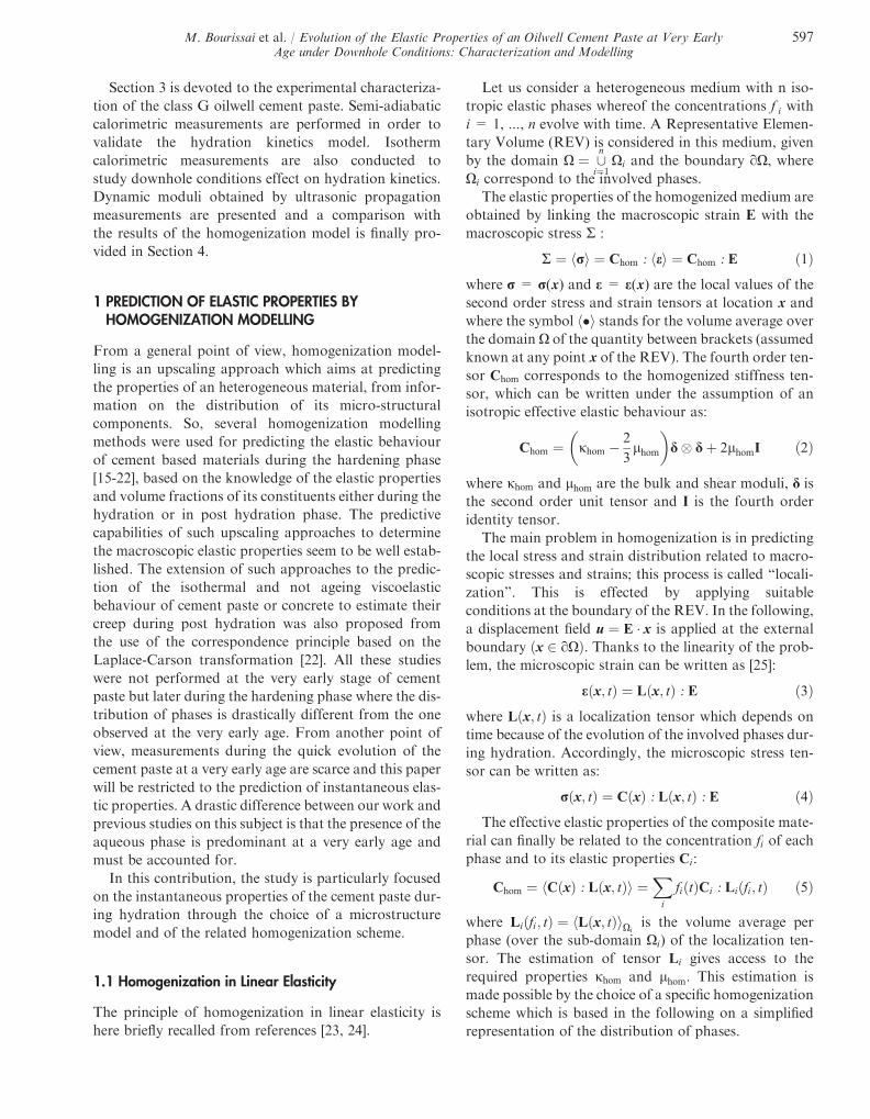
1.4 Multi-Scale Analysis
The homogenization process applied to the cement paste
requires to take into account some parameters which are
defined at different scales. Such scales (Fig. 5) can be
defined as follows:
Scale 0: C-S-H Gel
At the lowest scale, the C-S-H gel is heterogeneous. At
this scale, some mechanical properties of the C-S-H gel
are accessible by mechanical testing, i.e. nano-indenta-
tion (Tab. 1). The C-S-H gel exists under two different
forms: a Low Density (LD) C-S-H with a porosity of
roughly 37% and a High Density (HD) gel of around
24% of porosity [26]. The C-S-H gel is the dominant
Water
Anhydrous cement grain
Hydrates
Connected solid matrix(anhydrous + hydrate phases)
Figure 4
Representation of the morphological model of the hydrating cement paste during the second step of Figure 3.
Hydration time
Connected cement grains
Suspension of cement grains
Hydrates phase
Aqueous phase
Anhydrous cement phase
Figure 3
Evolution of the constituents of the cement paste during early age hydration.
M. Bourissai et al. / Evolution of the Elastic Properties of an Oilwell Cement Paste at Very EarlyAge under Downhole Conditions: Characterization and Modelling
599
Unconnected anhydrousphase
Connected solid matrix(anhydrous + hydrate phases)
Gel Porosity
AL
CH
SCALE IIHomogenized cement
pasteMacroscopic scale
SCALE IHydrates phase
10-6 – 10-4m
C-S-HHDC-S-HLD
Water
Unconnected hydratephase
SCALE '0'C-S-H gel matrix
10-8 – 10-6m
Figure 5
Upscaling method applied to the cement paste.
600 Oil & Gas Science and Technology – Rev. IFP Energies nouvelles, Vol. 68 (2013), No. 3
component of the forming cement paste skeleton and
may be regarded at the upper scale as a homogeneous
matrix connected with the other phases.
Scale I: Hydrates Phase
This scale is associated with the hydrates phase in
Figure 5 which is seen as a composite phase formed by
a C-S-H matrix surrounding portlandite (CH) and alu-
minates (AL).
Scale II: Homogenized Cement Paste
This is the upper scale corresponding to macroscopic
scale, that is the scale at which the elastic properties have
to be determined during the hydration process starting
from the intrinsic elastic properties of individual compo-
nents in these three defined scales and from their varying
volumetric concentrations.
1.5 Estimation of the Effective Elastic Properties
The volume fractions of all phases can be deduced at
each stage of the hydration process. However, the com-
posite spherical cell of Figure 5 is not completely defined
because hydrated and anhydrous phases appear in two
different parts of the composite sphere: one part named
“connected solid matrix” being the external spherical
layer, and the second one named “unconnected
hydrate/anhydrous phases” comprising the internal
sphere and its surrounding layer.
Some assumptions are therefore necessary to define
the concentrations of all phases. First (assumption 1),
without complementary information, the ratios between
volume fraction of hydrates and of anhydrous materials
are assumed to be the same within the two parts men-
tioned above. Next, an important point is to characterize
the ratio between the volume fractions of connected (fc)and unconnected (fu) parts.
Let us consider the volume fractions fc and fu of bothparts. It is obvious that fc is null at the beginning of the
hydration process and equal to 1 at the end of the hydra-
tion process.
Now, let us consider the ratio fcfuþfw
where fw is the vol-
ume fraction of water. This ratio tends to 0 when the
hydration ratio is null and becomes very large when
the hydration ratio tends to 1. A simple way to ensure
this property (assumption 2) is to assume that:
fcfu þ fw
¼ an
1� nð6Þ
where a is a constant parameter and n is the hydration
ratio whose definition is recalled in Section 2. Indeed,
if the hydration is complete (n=1) and if the initial quan-
tity of water is adjusted so that it is completely consumed
at the end of hydration, all the water and the anhydrous
materials are consumed at this stage (fw ¼ fu ¼ 0). And
therefore both ratios tend to infinity. At the beginning
of hydration (n=0) there is no hydrates and no con-
nected materials and therefore fc ¼ 0. Under the previ-
ous assumptions, these two limit cases are consistent
with the use of the previous relationship.
Finally, the use of assumption 1 for a given hydration
ratio allows the computation of the ratio of hydrates and
anhydrous components in the different spheres of
Figure 5. It produces the ratio of the radii of the smallest
spheres and the properties of the material contained in
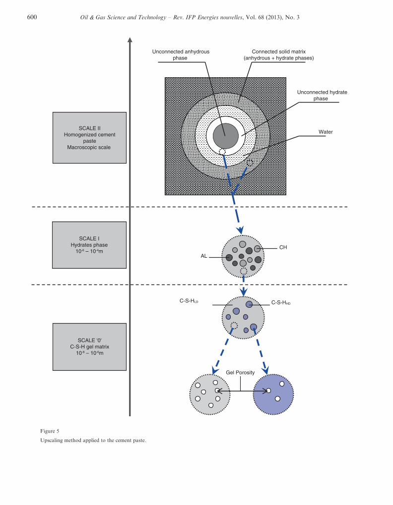
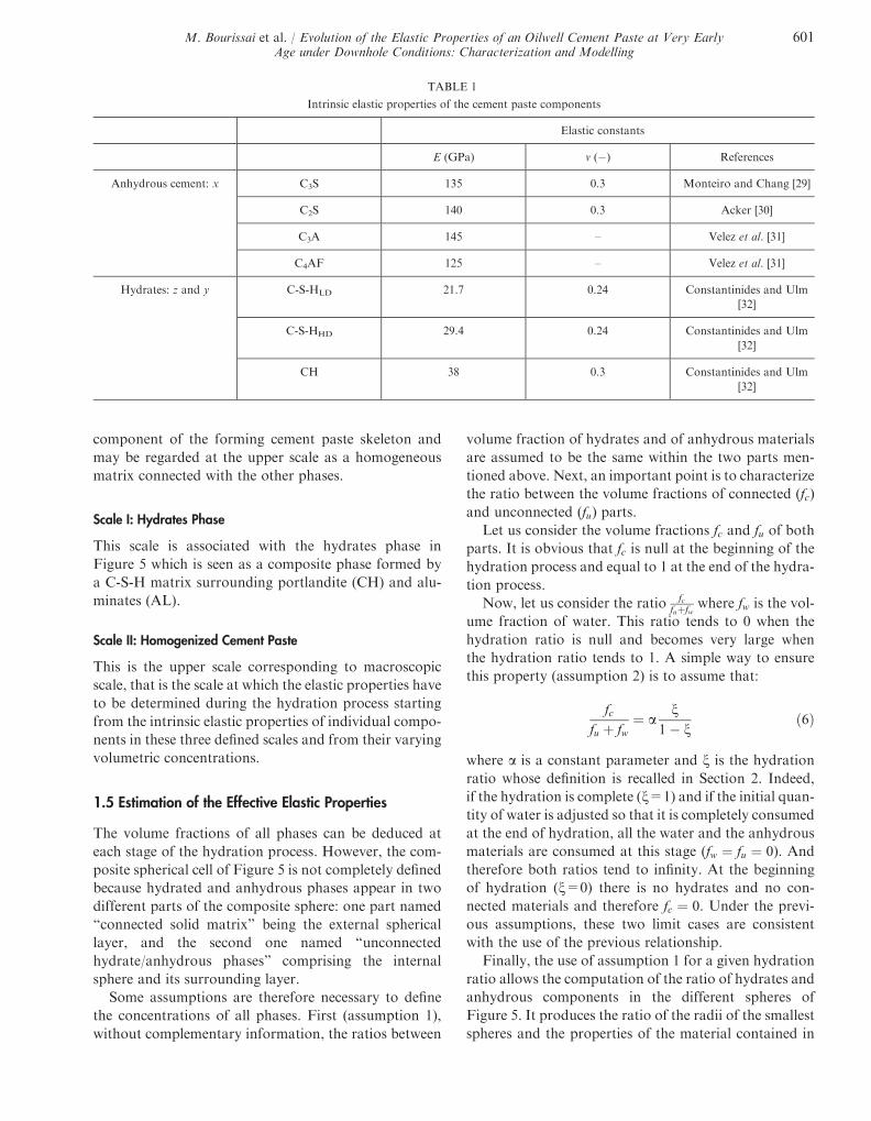
TABLE 1
Intrinsic elastic properties of the cement paste components
Elastic constants
E (GPa) v (�) References
Anhydrous cement: x C3S 135 0.3 Monteiro and Chang [29]
C2S 140 0.3 Acker [30]
C3A 145 – Velez et al. [31]
C4AF 125 – Velez et al. [31]
Hydrates: z and y C-S-HLD 21.7 0.24 Constantinides and Ulm
[32]
C-S-HHD 29.4 0.24 Constantinides and Ulm
[32]
CH 38 0.3 Constantinides and Ulm
[32]
M. Bourissai et al. / Evolution of the Elastic Properties of an Oilwell Cement Paste at Very EarlyAge under Downhole Conditions: Characterization and Modelling
601
the upper layer of the figure. The combination of
assumptions 1 and 2 allows the computation of the radii
of all spheres.
Finally, this set of assumptions allows the computa-
tion of all concentrations of phases in the composite
sphere model and leads to the theoretical estimation of
effective properties as follows.
For a given value of a, all volume fractions of the con-
stituents are known for any hydration ratio. Knowing
the elastic properties of hydrated and anhydrous phases
(see next subsection), the computation of elastic proper-
ties is performed in two steps.
A first step is to obtain the elastic properties of the
“connected solid matrix”. These properties are obtained
by using the GSC scheme (Appendix A) for two phases
(n = 2) with one central sphere made of anhydrous
phase and an external spherical layer made of hydrates,
the radii of spheres being obtained as explained before
by using assumption 1.
In a second step these properties are introduced in the
full 4-phases GSC scheme for obtaining the overall prop-
erties, the radii of the spheres being obtained from the
hydration ratio as previously. At this stage, the equa-
tions of Appendix A are again used for n = 4. These
equations produce the overall effective elastic moduli
of the cement paste.
2 MATERIAL INPUT DATA
Computing the homogenized bulk and shear moduli
jhom; lhomð Þ of the hydrating cement paste requires the
knowledge of the intrinsic elastic moduli of the cement
paste components at the different defined scales
(Fig. 5) and their volume fractions evolution during
hydration. The elastic properties at the lowest scales
are assumed to be intrinsic and taken from the literature
based on nano-indentation tests.
A first part of this section describes the simplified
homogenization scheme which is used for obtaining the
“mean” properties of hydrated and anhydrous phases,
knowing the properties of their constituents at a lower
scale.
The second part of this section describes the hydration
model which provides the evolution of the volume frac-
tions of all phases during hydration.
2.1 Mechanical Data
The hydrate phase contains all hydrates which are
formed during the hydration process. It is not possible
to account for the distribution of all these parts. How-
ever, the contrast between their mechanical properties
is not too high and the effect of the microstructure is
reduced, which induces that different homogenization
processes produce similar results. In addition, it is well-
known that the effective bulk modulus and shear modu-
lus are strictly comprised between two bounds made of
their volume mean value and of their volume harmonic
mean value. So a convenient simplified estimation of
the mean properties at this stage is provided by the mean
between these two bounds.
This estimation is used thereafter. Indeed, at the scale
‘0’ the elastic properties of the C-S-H matrix
jC�S�H ; lC�S�Hð Þ are first determined by volume aver-
ages obtained from the two types of C-S-H jz; lzð Þ withz = LD C-S-H and HD C-S-H:
jC�S�H ; lC�S�Hð Þ ¼Pzf z tð Þ jz; lzð Þ þ P
z
f z tð Þjz;lzð Þ
� ��1
2ð7Þ
where f z is the volume fraction of each type of C-S-H in
the C-S-H matrix. At the upper scale, the same estima-
tion from volume averages is used to determine the elas-
tic properties of the hydrates phase jh;lhð Þ from the
elastic properties of each hydrate component jy; ly� �
with y = homogenized C-S-H at the scale 0, portlandite
(CH) and aluminates (AL):
jh; lhð Þ ¼
Pyf y tð Þ jy; ly
� �þ Py
f y tð Þjy;lyð Þ
!�1
2
ð8Þ
in which f y is the volume fraction of each hydrated com-
ponent in the hydrates phase. Similarly, the elastic prop-
erties of the anhydrous cement ja; lað Þ are determined
from the elastic properties of each anhydrous compo-
nent jx; lxð Þ with x = C3S, C2S, C3A and C4AF:
ja; lað Þ ¼Pxf x tð Þ jx; lxð Þ þ P
x
f x tð Þjx;lxð Þ
� ��1
2ð9Þ
where f x is the volume fraction of each anhydrous com-
ponent in the anhydrous cement.
With regard to the elastic moduli of the solid phases,
Table 1 gives the available data at these scales in terms of
Young’s modulus E and of Poisson’s ratio obtained
from literature. Unfortunately, there is a lack of the elas-
tic properties of aluminates. Since the elastic properties
of C3S were carefully measured, Poisson’s ratio
value of C3S is simply used for C3A and C4AF.
For the aluminate hydrates, it is assumed that their
602 Oil & Gas Science and Technology – Rev. IFP Energies nouvelles, Vol. 68 (2013), No. 3

properties are similar to the elastic properties of the C-S-
H matrix provided by Equation (7). Using the values
obtained from Table 1, the elastic bulk and shear moduli
for the solid compounds jx; lx; jy; ly; jz; lz� �
are com-
puted according to the classical relationships of elastic-
ity. This set must be completed by the elastic
properties of the aqueous phase, whose bulk modulus
is jw(20�C) = 2.18 GPa and jw(60�C) = 2.25 GPa
[28], its shear modulus being null.
2.2 Data Coming from the Chemical Hydration Model
The volume fractions of the different phases inside the
cement paste are continuously evolving during the
hydration process. So, the main objective of this section
is to provide the volume fractions evolution of the phases
during the hydration process. This requires two steps:
– the description of the evolution of the hydration
degree from kinetics laws of reactions related to the
hydration of each anhydrous phase;
– the determination of the evolution of volume fractions
of associated hydration products together with the
progressive decrease of anhydrous components and
aqueous phase.
2.2.1 Hydration Model
The hydration process of each compound x is expressed
in terms of its degree of hydration nx which is one minus
the ratio of the unreacted mass mx of each anhydrous
component to its initial mass m0x :
nx tð Þ ¼ 1� mx tð Þm0
x
ð10Þ
In this subsection, kinetics laws based on chemical
affinity are used for the description of the cement hydra-
tion [20]. These laws were found suitable for the predic-
tion of the cement hydration during all hydration stages
and easily incorporated within the framework of a chem-
ically reactive [33] porous medium.
Therefore, the cement hydration kinetics reads:
dnxdt
¼ 1
sx T ;/ð Þ~Ax nxð Þ ð11Þ
where ~Ax -ð Þ is the normalized chemical affinity, sx hourð Þdenotes the characteristic time of the chemical reaction,
which depends on the temperature T, the current Blaine
surface area /, the type of clinker mineral and the water
to cement ratio w/c.
Furthermore, dependence of the hydration reaction
on temperature is considered to be described according
to Arrhenius equation [34] by reducing the characteristic
time of the reaction as:
sx T ;/ð Þ ¼ sx T0;/0ð Þ/0
/exp
Exa
R
1
T� 1
T0
� �� �ð12Þ
where sx T0;/0ð Þ is the characteristic time of the chemical
reaction [15] at the reference temperature T0 = 293 K,
/0 = 3 602 cm2.g�1 is a reference fineness of cement,
Exa is the activation energy of each component x and R
is the gas constant.
Moreover, experimental results obtained from iso-
thermal calorimetric measurements with DSC (Fig. 8a
in Sect. 3.1.1) have allowed to verify the existence of
three hydration stages in the period concerned in our
study. The normalized affinity takes then three particu-
lar expressions according to the stage as reported in [20]:
1. Induction stage, at which the dissolution of clinker
occurs.
2. Growth stage characterized by a nucleation process
accompanied by reaction acceleration and formation
of hydration products.
3. Diffusion stage which corresponds to the process dur-
ing which ions diffuse through a thickening layer of
hydration products toward anhydrous cement grains.
During the induction stage t < t0x and nx tð Þ < n0x� �
, the
reaction is very slow, which allows to assume that it does
not evolve practically during this stage. In this case, the
chemical affinity is assumed constant, which implies~Ax ¼ 1 [20, 21]. The stage duration, noted t0x , reads:
t0x ¼ n0x :sx T ;/ð Þ ð13Þ
where n0x is the critical degree of hydration at the
end of the pre-induction which is characterized by an
instantaneous release of heat. The degree of hydration
during this stage is then given by:
nx tð Þ ¼ n0xH tð Þ ð14Þ
where H tð Þ is the Heaviside step function.
During the growth stage t0x < t < tgx and�
n0x < nx tð Þ < ngxÞ of upper limit-time tgx , the normalized
affinity ~Agx is given by Avrami’s model:
~Agx nxð Þ ¼ 1� nx
� ln 1� nxð Þð ÞK�1x �1
ð15Þ
In addition, the characteristic time associated with the
growth stage writes:
sgx T0ð Þ ¼ 1
Kx:kxð16Þ
M. Bourissai et al. / Evolution of the Elastic Properties of an Oilwell Cement Paste at Very EarlyAge under Downhole Conditions: Characterization and Modelling
603

The parameter Kx defines reaction order whereas kxrepresents the rate constant.
During the diffusion stage t > tgx and nx tð Þ > ngx� �
, the
normalized affinity ~Adx is given by the model of Fuji and
Kondo:
~Adx nxð Þ ¼ 1� nxð Þ2=3
1� ndx� �1=3 � 1� nxð Þ1=3
ð17Þ
where ndx is the critical hydration degree at the end of the
growth stage.
The characteristic time sdx T0ð Þ is obtained from the
diffusion coefficient D and from the initial radius r of
the cement grain, by:
sdx T 0ð Þ ¼ r2
3Dð18Þ
The values of parameters used in this paper are sum-
marized in Table 2. They were interpolated from data
published in [20]. The diffusion coefficient values were
deduced from the fitting of the present hydration model
to the experimental hydration data of Escalante-Garcia
and Sharp [35] for each cement component.
Finally the overall degree of hydration n tð Þ is obtainedfrom the values of the partial hydration degree nx tð Þ ofeach anhydrous cement component x as follows:
n tð Þ ¼Pxm0
xnx tð Þm0
a
¼Xx
f mx nx tð Þ ð19Þ
where m0a ¼
Pxm0
x is the initial total mass of the anhy-
drous cement and f mx is the initial mass fraction of each
anhydrous component.
An alternative estimation, nQ, of the hydration degree
can be directly related to results of Q tð Þ obtained from
calorimetric measurement (semi-adiabatic) which will
be used thereafter. It is given by:
nQ tð Þ ¼ Q tð ÞQ1 ð20Þ
where:
Q1 ¼Xx
f mx q1x ð21Þ
Q tð Þ is the current heat of hydration, Q1 is its asymp-
totic value released at full hydration nQ ¼ 1� �
. It is
important to note that Q1 depends on q1x , the corre-
sponding asymptotic value for each component x, whose
experimental data show a certain dispersion in the liter-
ature (Tab. 3).
Equation (22) shows an equivalent expression of
Equation (20) with Q tð Þ deduced from the current hydra-
tion heat of each component x.
nQ tð Þ ¼Pxf mx q
1x nx tð ÞP
xf mx q
1x
ð22Þ
TABLE 2
Hydration kinetics model parameters for w/c = 0.44
Anhydrous cement components
Model parameters C3S C2S C3S C4AF
Ea=RðKÞ 4 500 2 500 5 500 4 200
n0xð�Þ 0.02 0.00 0.04 0.04
Kxð�Þ 1.78 1.01 1.04 2.34
ndx ð�Þ 0.6 0.6 0.6 0.6
23�C sgxðhÞ 12.21 69.13 48.43 22.69
sdx ðhÞ 5 041.53 27 013.31 695.73 72 773.18
Dðcm2:h�1Þ 1.2 9 10�10 1.0 9 10�11 3.5 9 10�10 3.5 9 10�12
60�C sgxðhÞ 2.26 27.04 6.15 4.70
sdx ðhÞ 1 592.07 1 472.67 294.53 9 817.78
Dðcm2:h�1Þ 18.5 9 10�11 20.0 9 10�11 1.0 9 10�9 3.0 9 10�11
604 Oil & Gas Science and Technology – Rev. IFP Energies nouvelles, Vol. 68 (2013), No. 3

2.2.2 Volume Fractions Evolution during the Hydration Process
The hydration kinetics, Equations (11)-(18), for each
anhydrous cement component are used for determining
the evolution of the volume fractions related to the dif-
ferent phases of the cement paste during hydration.
At each time t, the volumes of remaining anhydrous
cement Va, of water Vw, of the formed hydrates contain-
ing gel porosity Vh and of capillary porosity Vp are deter-
mined. The volume of the cement paste Vc is then given
by:
Vc tð Þ ¼ Va tð Þ þ Vw tð Þ þ Vh tð Þ þ Vp tð Þ ð23Þ
In this work, the cement paste volume is assumed con-
stant during hydration, which means that bulk shrinkage
is neglected with regard to volume variation:
Vc tð Þ ¼ V 0c ¼ V 0
a þ V 0w ð24Þ
where V 0a and V 0
w are the initial volumes of anhydrous
cement and water in the mixture.
The volume fractions for each phase of the cement
paste are given by:
fa tð Þ ¼ Va tð ÞV 0
c
; fw tð Þ ¼ Vw tð ÞV 0
c
; fh tð Þ ¼ Vh tð ÞV 0
c
; fp tð Þ ¼ Vp tð ÞV 0
c
ð25Þ
with fa tð Þ þ fw tð Þ þ fh tð Þ þ fp tð Þ ¼ 1.More suitable forms of volume fraction expressions
can be obtained by considering stoichiometry of the
hydration reactions of the four main cement components
C3S, C2S, C3A, C4AF:
C3Sþ 5:3H ! 0:5C3:4S2H8 þ 1:3CH ð26ÞC2Sþ 4:3H ! 0:5C3:4S2H8 þ 0:3CH ð27Þ
C4AFþ 2CHþ 10H! 2C3 A; Fð ÞH6 ðHydrogarnetÞ ð28ÞC3Aþ 3C�SH2 þ 26H!C6A�S3H32 Ettringite ðAFtÞ ð29Þ
C3Aþ 0:5C6A�S3H32 þ 2H ! 1:5C4A�SH12
Monosulfate ðAFmÞ ð30Þ
C3Aþ CHþ 12H! C4AH13 Calcium aluminate hydrate
ð31Þ
The hydration reactions of C3A have to be particu-
larly considered with care because they occur at different
stages in the presence of gypsum and overlap each other.
The ettringite which is a stable product is first formed
(Eq. 29), and when the gypsum C�SH2ð Þ is consumed,
the ettringite becomes unstable and further hydration
yields the monosulfate (Eq. 30). Then, calcium aluminate
hydrate may be formed (Eq. 31) if C3A is not completely
consumed after the formation of AFm (Eq. 30). The C3A
reactions rate also depends on several factors such as
temperature, w/c ratio and grain size [36]. Furthermore,
the initial mass of C3A represents only 2% of the initial
mass of the studied anhydrous cement (Tab. 4). Conse-
quently, an approximation is made by considering that
C3A is assimilated to C4AF and only the hydration reac-
tion of the C4AF which forms the hydrogarnet (Eq. 28) is
considered to describe the volume fraction evolution of
the aluminate hydrates.
According to [20], the volume fractions of the differ-
ent phases of the cement paste can finally be written
in terms of stoichiometric ratios h of the chemical reac-
tions Equations (26)-(31), mass densities q and molar
masses M:
fa tð Þ ¼ f 0aXx
1� nx tð Þð Þf 0xqxqa
ð32Þ
fw tð Þ ¼ f 0w � f 0aXx
hxwf0x
qxqw
Mw
Mxnx tð Þ
� �ð33Þ
fh tð Þ ¼ f 0aXy
Xx
hxyMy
Mx
qxqh
f 0x nx tð Þ !
ð34Þ
fp tð Þ ¼ 1� fw tð Þ � fa tð Þ � fh tð Þ ð35Þ
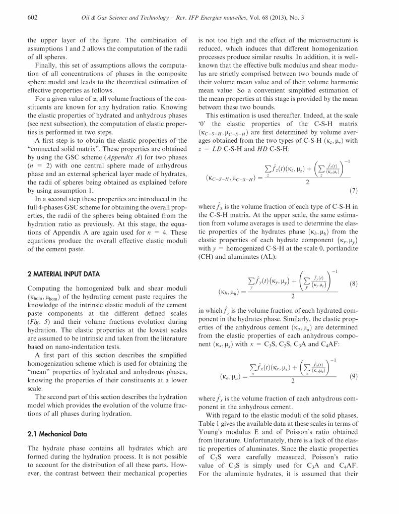
Figure 6 presents the volume fractions evolution dur-
ing the hydration of a class G cement paste. The con-
sumption of the anhydrous cement and water during
the hydration reactions results in the formation of
TABLE 3
Asymptotic values of hydration heat for each component x
The Heat of hydration (J.g�1)
q1C3Sq1C2S
q1C3Aq1C4AF
Taylor [36] 517 262 1 144 418
Chougnet et al. [37] 520 70 1 670 725
M. Bourissai et al. / Evolution of the Elastic Properties of an Oilwell Cement Paste at Very EarlyAge under Downhole Conditions: Characterization and Modelling
605
hydrates containing the gel porosity and the capillary
porosity. At complete hydration n ¼ 1ð Þ, all the
anhydrous cement is consumed, fC-S-H = 59.1%,
fCH = 12.8%, fAL= 15.3%. The remaining water con-
tent (fw = 2.2%) and the formed capillary porosity
(fp = 10.6%) provide the macro porosity of 12.8%. Sim-
ilar trends were also obtained by Taylor [36] and Hansen
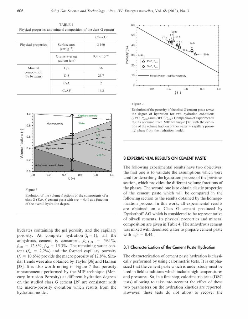
[38]. It is also worth noting in Figure 7 that porosity
measurements performed by the MIP technique (Mer-
cury Intrusion Porosity) at different hydration degrees
on the studied class G cement [39] are consistent with
the macro-porosity evolution which results from the
hydration model.
3 EXPERIMENTAL RESULTS ON CEMENT PASTE
The following experimental results have two objectives:
the first one is to validate the assumptions which were
used for describing the hydration process of the previous
section, which provides the different volume fractions of
the phases. The second one is to obtain elastic properties
of the cement paste which will be compared in the
following section to the results obtained by the homoge-
nization process. In this work, all experimental results
are obtained on a Class G cement produced by
Dyckerhoff AG which is considered to be representative
of oilwell cements. Its physical properties and mineral
composition are given in Table 4. The anhydrous cement
was mixed with deionized water to prepare cement paste
with w/c = 0.44.
3.1 Characterization of the Cement Paste Hydration
The characterization of cement paste hydration is classi-
cally performed by using calorimetric tests. It is empha-
sized that the cement paste which is under study must be
used in field conditions which include high temperatures
and pressures. So, in a first step, calorimetric tests (DSC
tests) allowing to take into account the effect of these
two parameters on the hydration kinetics are reported.
However, these tests do not allow to recover the
Vol
ume
frac
tions
(−
)
1.0
0.6
0.8
0.4
0.00.0 0.2 1.00.80.60.4
0.2
Macro-porosity
Hydrates phase
Anhydrous cement phase
Capillary porosity
Water
AL
CH
C-S-HHD
C-S-HLD
ξ (−)
Figure 6
Evolution of the volume fractions of the components of a
class G (Tab. 4) cement paste with w/c= 0.44 as a function
of the overall hydration degree.
20 h
24 h
24 h7 h
72 h
120 h
17 h4 h
MIP:
23˚C, Patm
60˚C, Patm
Model: Water + capillary porosity
60
50
40
30
20
10
00.2 0.4 0.6 0.8 1.0
Por
osity
(%
)
(−)ξ
Figure 7
Evolution of the porosity of the class G cement paste versus
the degree of hydration for two hydration conditions
(23�C, Patm) and (60�C, Patm). Comparison of experimental
results obtained from MIP technique [39] with the evolu-
tion of the volume fraction of the (water + capillary poros-
ity) phase from the hydration model.
TABLE 4
Physical properties and mineral composition of the class G cement
Class G
Physical properties Surface area
(cm2�g�1)
3 160
Grains average
radium (cm)
9.4 9 10�4
Mineral
composition
(% by mass)
C3S 56
C2S 25.7
C3A 2
C4AF 16.3
606 Oil & Gas Science and Technology – Rev. IFP Energies nouvelles, Vol. 68 (2013), No. 3

hydration ratio, for which the evaluation of the heat pro-
duced during hydration must be estimated. So a second
series of tests was performed by using the Langavant cal-
orimeter. This last method allowed to recover the heat
produced during hydration and therefore the hydration
ratio.
3.1.1 Temperature and Pressure Effects
Calorimetric measurements were performed using an
isotherm calorimeter (HP micro DSC VII). Such a calo-
rimeter allows to study the temperature (T) and the pres-
sure (P) effects on the hydration kinetics by following the
heat flow emitted during cement paste hydration under
downhole conditions. The tests conditions are summa-
rized in Table 5.
Figure 8a shows that when curing temperature is ele-
vated (60�C), the threemain phases of hydration duration
are significantly reduced and the exothermic heat flow
peak is higher than the heat flow evolution at 23�C.Indeed, it is well known that the increase of curing tem-
perature accelerates the hydration reactions of the cement
paste [35, 40]. However, the effect of pressure on the
hydration kinetics is by far less remarkable than the one
induced by the temperature (Fig. 8b). A slight shift of
the peak in the heat flow reveals somehow an acceleration
of the hydration reactions. The amount of heat is also
slightly increased.Nevertheless this effect can be assumed
to be negligible with regard to the involved contrast of
pressure. The pressure effect is consequently assumed
negligible in this work, and it is no more considered
below.
These results provide interesting qualitative informa-
tion on the hydration process, but do not provide an
overall heat production which is necessary for obtaining
the “calorimetric” hydration degree. So, the hydration
kinetics is provided in the following section by using
an alternative calorimetric set-up.
3.1.2 Determination of Hydration Kinetics from CalorimetricData
The Langavant semi-adiabatic calorimeter was used to
quantify the heat Q tð Þ emitted during the exothermic
chemical reactions between anhydrous cement and
water. Such a calorimeter can be used only at atmo-
spheric pressure. The overall hydration degree is then
calculated by using Equation (20) where Q tð Þ is the mea-
sured hydration heat. This measurement allows to vali-
date the overall hydration degree obtained from the
hydration model of the previous section. However, this
comparison is possible at the condition to know the total
heat production. This total production has been evalu-
ated by using two different kinds of estimations coming
from the literature, as shown in Figure 9, which displays
predicted (from Sect. 2) and measured estimations of the
overall hydration degree. The comparison between
experimental and predicted values shows that the model
overestimates the overall heat flow at early times, but
that it recovers the main trends provided by experimen-
tal results.
TABLE 5
Experimental conditions of DSC tests
Test 1 Test 2 Test 3 Test 4
T (�C) 23 23 60 60
P (Pa) 105 200 9 105 105 200 9 105
00 4 8 12 16 20 24 28
10
20
30
40
50
60
(3)(2)
(1) (3)(2)(1)
Time (h)
0 4 8 12 16 20 24 28
Time (h)
Hea
t flo
w (
j.g-1.h
-1)
23°C, P = 200.105 Pa
60°C, P = 200.105 Pa
60°C, P = 200.105 Pa
a)
0
10
20
30
40
50
60
Hea
t flo
w (
j.g-1.h
-1)
b)
60°C, Patm
Figure 8
Time evolution of hydration heat flow per unit mass of the
studied cement for two curing conditions: experimental
results from isotherm calorimetric conditions with DSC.
a) 23�C and 60�C under Nitrogen pressure equal to
200 9 105 Pa. b) 60�C under two different pressures: Patm
and 200 9 105 Pa.
M. Bourissai et al. / Evolution of the Elastic Properties of an Oilwell Cement Paste at Very EarlyAge under Downhole Conditions: Characterization and Modelling
607
These results must be evaluated in view of all the
assumptions used in the modelling process and by con-
sidering the two types of tests which were used in this
study.
There are indeed a few assumptions during the model-
ling of the hydration process which should need a further
scrutiny:
– the use of the equation of Arrhenius to describe the
temperature effect;
– Avrami’s model for the normal affinity;
– Fuji and Kondo’s model for the normalized affinity
during the diffusion stage;
– the use of parameters of Table 2, which correspond to
data coming from measurements on materials which
can be different from the paste under study.
In view of these assumptions, the comparison between
calorimetric data and modelling results shows that these
assumptions are realistic for the cement paste under
study.
In addition, the use of two kinds of calorimetric tests
allowed to show that the pressure has a secondary effect
on hydration compared to the temperature which
strongly influences the hydration process. These results
are obviously of importance for the use of the cement
paste in field conditions.
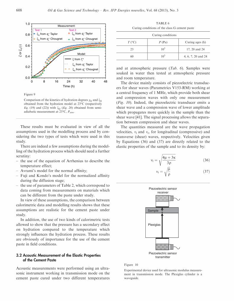
3.2 Acoustic Measurement of the Elastic Propertiesof the Cement Paste
Acoustic measurements were performed using an ultra-
sonic instrument working in transmission mode on the
cement paste cured under two different temperatures
and at atmospheric pressure (Tab. 6). Samples were
soaked in water then tested at atmospheric pressure
and room temperature.
The device mainly consists of piezoelectric transduc-
ers for shear waves (Parametrics V153-RM) working at
a central frequency of 1 MHz, which provide both shear
and compression waves with only one measurement
(Fig. 10). Indeed, the piezoelectric transducer emits a
shear wave and a compression wave of lower amplitude
which propagates more quickly in the sample than the
shear wave [41]. The signal processing allows the separa-
tion between compression and shear waves.
The quantities measured are the wave propagation
velocities, vl and vt, for longitudinal (compressive) and
transverse (shear) waves, respectively. Velocities given
by Equations (36) and (37) are directly related to the
elastic properties of the sample and to its density by:
vl ¼ffiffiffiffiffiffiffiffiffiffiffiffiffiffiffiffi4lþ 3j
3q
sð36Þ
vt ¼ffiffiffilq
rð37Þ
0 8 16 24 32 40 48
Time (h)
0.0
0.2
0.4
0.6
0.8
1.0
ξQ from qx∞ Taylor
ξQ from qx∞ Taylor
ξQ from qx∞ Taylor
ξ from fxm
ξQ from qx∞ Chougnet
ξQ from qx∞ Chougnet
ξQ from qx∞ Chougnet
Test 1 Test 2
Measurement:
Model:
ξξ
orQ
(-)
Figure 9
Comparison of the kinetics of hydration degrees vQ and nQobtained from the hydration model at 23�C (respectively
Eq. (19) and (22)) with nQ (Eq. 20) obtained from semi-
adiabatic measurement at 23�C, Patm.
TABLE 6
Curing conditions of the class G cement paste
Curing conditions
T (�C) P (Pa) Curing ages (h)
23 105 17, 20 and 24
60 105 4, 6, 7, 20 and 24
Piezoelectric sensorreceiver
Piezoelectric sensortransmitter
Sample
Plexiglas
Figure 10
Experimental device used for ultrasonic modulus measure-
ment in transmission mode. The Plexiglas cylinder is a
waveguide.
608 Oil & Gas Science and Technology – Rev. IFP Energies nouvelles, Vol. 68 (2013), No. 3

The dynamic bulk jð Þ and shear lð Þ moduli of the
cement paste are then calculated from Equations (36)
and (37) as:
j ¼ q3v2l � 4v2t
3ð38Þ
l ¼ qv2t ð39Þ
It was not possible to measure the dynamic elastic mod-
uli of cement pastes until the transition from a suspen-
sion containing non-cohesive solid particles to a
cohesive skeleton occurs. At this time, the shear waves
may propagate throughout the forming interconnected
solid network [6].
Figure 11 shows the dynamic elastic moduli evolution
of the studied class G cement paste measured at 23�C and
60�C (Tab. 6). Thesemoduli quickly increase at early ages
and then increase more slowly when hydration slows
down. The values of the dynamic elastic moduli for the
first curing age either at 23�C or 60�C are similar.
Figure 11 shows also, that for the same curing age, the val-
ues of the dynamic elastic moduli at 60�C are higher than
those obtained at 23�C, this result being obviously due tothe acceleration of the hydration process when increasing
the temperature.
4 COMPARISON BETWEEN THEORETICAL ANDEXPERIMENTAL RESULTS
Figure 12 shows the comparison between evolution of
elastic moduli with time obtained experimentally and
from the homogenization process. The homogenized
elastic moduli are obtained by introducing the different
volume fractions shown in Figure 6 together with
mechanical parameters given in Section 2.1, into expres-
sions related to the use of GSC homogenization scheme
in a two-step process, as previously described. Different
values of parameter a were introduced. The results show
that experimental moduli compare well with the theoret-
ical results obtained from the highest value of a, i.e.a = 0.5, the experimental moduli being slightly higher
than theoretical ones. Obviously, the comparison
between experimental results obtained by wave propaga-
tion and theoretical results coming from the hydration
data combined with the homogenization process must
be appreciated by taking into account the simplifications
used in the process. These simplifications include:
– the use of a simplified homogenization model in
which the grains of connected material are assumed
spherical, knowing that this grain shape is far from
real grain shapes which are very irregular;
κ_23˚C κ_60˚C
μ_23˚C μ_60˚C
60˚C
60˚C
23˚C
23˚C10
8
6
4
2
0 4 8 12 16 20 24 28
12
14
Time (h)
Ela
stic
Mod
uli (
GP
a )
Figure 11
Evolution of dynamic elastic moduli of the class G cement
paste with curing age. The dynamic moduli are measured
by ultrasonic method at 23�C (solid symbols) and 60�C(open symbols).
κhom (α = 0.3)
κdynamic
μdynamic
μhom (α = 0.5)
μhom (α = 0.4)
μhom (α = 0.3)
κhom (α = 0.5)
κhom (α = 0.4)
12
10
8
6
4
2Ela
stic
mod
uli (
GP
a)
0
(23°C, Patm)
a)
12 2016 24 28840Hydration time (h)
0.02 0.08 0.17 0.28 0.38 0.46 0.50 0.53ξ (−)
(60°C, Patm)12
10
8
6
4
2
0
Ela
stic
mod
uli (
GP
a)
12 2016 24 28840Hydration time (h)
b)0.02 0.44 0.55 0.59 0.63 0.66 0.68 0.71
ξ (−)
κhom (α = 0.3)
κdynamic
μdynamic
μhom (α = 0.5)
μhom (α = 0.4)
μhom (α = 0.3)
κhom (α = 0.5)
κhom (α = 0.4)
Figure 12
Early-age homogenized elastic moduli jhom;lhomð Þ com-
pared with dynamic elastic moduli measured by ultrasonic
method jdynamic;ldynamic
� �a) at 23�C and b) at 60�C versus
hydration time/hydration degree (class G cement paste,
w/c = 0.44).
M. Bourissai et al. / Evolution of the Elastic Properties of an Oilwell Cement Paste at Very EarlyAge under Downhole Conditions: Characterization and Modelling
609

– the two assumptions which were used for obtaining
the concentrations of each constituent in the compos-
ite sphere, which constitute certainly a simplification;
– the assumptions taken into account for modelling the
hydration which were stated in Section 2.
However, despite all these simplifications, the
comparison shows a good consistency between experi-
mental and theoretical results. It shows that the main
characteristics are taken into account. Indeed, the main
points in this kind of modelling are to respect the connec-
tivity of the phases and to have a correct evaluation of
the concentrations of the different phases. The good con-
sistency between experimental and theoretical results
shows that these main points are respected in the whole
process.
CONCLUSIONS
This paper dealt with the very early-age cement paste
characterization and with the modelling of the elastic
properties development under elevated temperature
and high pressure frequently encountered in oil and
gas wells where they have to be addressed.
Isothermal calorimetric measurements have shown an
acceleration of the hydration kinetics with temperature
and also a negligible effect of pressure on hydration kinet-
ics in the range of the tested pressure.Ahydration kinetics
model based on chemical affinity was used to take into
account the temperature effect on cement paste hydra-
tion. The model results are in a good agreement with
the performed semi-adiabaticmeasurements of hydration
heat. Then, the development of cement paste elastic prop-
erties was predicted from the use of a multiphase homog-
enization model, based on the evolving volume fractions
of components of the hydrating cement paste determined
from the hydration kineticsmodel and from themicrome-
chanical properties of the multiphase cement paste at
multiple scales. The elastic moduli results obtained
from the multiscale homogenization approach coupled
with the hydrationmodel, at 23�Cand 60�Ccomparewell
with the dynamic moduli obtained from acoustic mea-
surements at the same temperatures.
ACKNOWLEDGMENTS
The authors are particularly grateful to Florence Adje-
mian (IFPEN) for fruitful discussions concerning
primary cementing technique in wells and Laurent Can-
gemi (IFPEN) for stimulating discussions during the
course of this work. The authors also want to express
their special acknowledgement to Nathalie Ferrer and
Alain Rivereau (IFPEN) for their technical support dur-
ing the experimental part of the study and to Hoang Duc
Hieu (MSME) who strongly helped for the computa-
tions related to the GSC homogenization scheme.
REFERENCES
1 Thiercelin M.J., Dargaud B., Baret J.F., Rodriguez W.J.(1997) Cement design based on cement mechanicalresponse, SPE Annual Technical Conf. and Exhibition(ATCE ’97), San Antonio, Texas, 5-8 Oct., pp. 337-347.
2 Bosma M., Ravi K., Van Driel W., Jan Schreppers G.(1999) Design approach to sealant selection for the life ofthe well, 74th SPE Annual Technical Conf. and Exhibition(ATCE ’99), Houston, Texas, 3-6 Oct., pp. 1-14.
3 Di Lullo G., Rae P. (2000) Cements for long term isolation –design optimization computer modelling and prediction,2000 IADC/SPE Asia Pacific Drilling Technology, KualaLumpur, Malaysia, 11-13 Sept., SPE 62745-MS, pp. 1-14.
4 Boukhelifa L., Moroni N., James S.G., Le Roy-Delage S.,Thiercelin M.J., Lemaire G. (2004) Evaluation of cementsystems for oil and gas well zonal isolation in a full-scaleannular geometry, IADC/SPE Drilling Conference, Dallas,Texas, 2-4 March, SPE 87195-MS, pp. 44-53.
5 D’Angelo R., Plona T.J., Schwartz L.M., Coveney P. (1995)Ultrasonicmeasurements on hydrating cement slurries: onsetof shear wave propagation, Adv. Cem. Bas. Mat. 2, 1, 8-14.
6 Boumiz A., Vernet C., Cohen-Tenoudji F. (1996) Mechan-ical properties of cement pastes and mortars at early ages,Adv. Cem. Bas. Mat. 3, 3-4, 94-106.
7 Lacouture J.C., Johnson P.A., Cohen-Tenoudji F. (2003)Study of critical behavior in concrete during curing byapplication of dynamic linear and nonlinear means, J. Ac-oust. Soc. Am. 113, 3, 1325-1332.
8 Lootens D., Hebraud P., Lecolier E., Van Damme H.(2004) Gelation, shear-thinning and shear-thickening incement slurries, Oil Gas Sci. Technol. 59, 1, 31-40.
9 Sun Z., Voigt T., Shah S.P. (2006) Rheometric and ultra-sonic investigations of viscoelastic properties of fresh Port-land cement pastes, Cem. Concr. Res. 36, 2, 278-287.
10 Trtnik G., Turk G., Kavcic F., Bosiljkov V.B. (2008) Pos-sibilities of using ultrasonic wave transmission method toestimate initial setting time of cement paste, Cem. Concr.Res. 38, 11, 1336-1342.
11 Voigt T., Shah S.P. (2004) Properties of early-age Portlandcement mortar monitored with shear wave reflectionmethod, ACI Materials J. 101, 6, 473-482.
12 Ye G., van Breugel K., Fraaij A.L.A. (2003) Experimentalstudy and numerical simulation on the formation of micro-structure in cementitious materials at early age, Cem. Con-cr. Res. 33, 2, 233-239.
13 Voigt T., Malonn T., Shah S.P. (2006) Green and early agecompressive strength of extruded cement mortar monitoredwith compression tests and ultrasonic techniques, Cem.Concr. Res. 36, 858-867.
14 Reddy B.R., Santra A., McMechan D., Gray D., BrenneisC., Dunn R. (2007) Cement mechanical property measure-ments under wellbore conditions, SPE Drill. Complet. 22,1, 33-38.
610 Oil & Gas Science and Technology – Rev. IFP Energies nouvelles, Vol. 68 (2013), No. 3

15 Sanahuja J., Dormieux L., Chanvillard G. (2007) Model-ling elasticity of a hydrating cement paste, Cem. Concr.Res. 37, 10, 1427-1439.
16 Torrenti J.M., Benboudjema F. (2005) Mechanical thresh-old of cementitious materials at early age, Mater. Struct.38, 277, 299-304.
17 Haecker C.-J., Garboczi E.J., Bullard J.W., Bohn R.B., SunZ., Shah S.P., Voigt T. (2005) Modeling the linear elasticproperties of Portland cement paste, Cem. Concr. Res. 35,10, 1948-1960.
18 Bishnoi S., Scrivener K.L. (2009) lic: A new platform formodelling the hydration of cements, Cem. Concr. Res. 39,4, 266-274.
19 Garboczi E., Bullard J. (2009) Virtual concrete in real time,Concrete Producer 27, 4, 19-22.
20 Bernard O., Ulm F.J., Lemarchand E. (2003) A Multiscalemicromechanics-hydration model for the early-age elasticproperties of cement-based materials, Cem. Concr. Res.33, 9, 1293-1309.
21 Ghabezloo S. (2010) Association of macroscopic labora-tory testing and micromechanics modelling for the evalua-tion of the poroelastic parameters of a hardened cementpaste, Cem. Concr. Res. 40, 8, 1197-1210.
22 Le Q.V., Meftah F., He Q.C., Le-Pape Y. (2008) Creep andrelaxation functions of a heterogeneous viscoelastic porousmedium using the Mori-Tanaka homogenization schemeand a discrete microscopic retardation spectrum, Mech.Time-Dependent Mater. 11, 3-4, 309-331.
23 Nemat-Nasser S., Hori M. (1999) Micromechanics: overallproperties of heterogeneous materials, North Holland,Amsterdam.
24 Milton G. (2002) The theory of composites, Cambridge Uni-versity Press, Dordrecht.
25 Zaoui A. (1997) Materiaux heterogenes et composites,Courses of the Ecole Polytechnique, Palaiseau, France.
26 Tennis P.D., Jennings H.M. (2000) A model for twotypes of calcium silicate hydrate in the microstructureof Portland cement pastes, Cem. Concr. Res. 30, 6,855-863.
27 Herve E., Zaoui A. (1993) n-Layered inclusion-based mi-cromechanical modelling, Int. J. Eng. Sci. 31, 1, 1-10.
28 Kell G.S. (1975) Density, thermal expansivity and com-pressibility of liquid water from 0� to 150�C: correlationsand tables for atmospheric pressure and saturationreviewed and expressed on 1968 temperature scale, J.Chem. Eng. Data 20, 1, 97-105.
29 Monteiro P.J.M., Chang C.T. (1995) The elastic moduli ofcalcium hydroxide, Cem. Concr. Res. 25, 8, 1605-1609.
30 Acker P. (2001) Micromechanical analysis of creep andshrinkage mechanisms, creep, shrinkage and durabilitymechanics of concrete and other quasi-brittle materials,Proc. of the 6th International Conference CONCREEP6,Cambridge, MA, USA, 20-22 Aug, Elsevier, Oxford,UK, pp. 15-25.
31 Velez K., Maximilien S., Damidot D., Fantozzi G.,Sorrentino F. (2001) Determination by nanoindentationof elastic modulus and hardness of pure constituents ofPortland cement clinker, Cem. Concr. Res. 31, 4, 555-561.
32 Constantinides G., Ulm F.J. (2004) The effect of two typesof C–S–H on the elasticity of cement-based materials:results from nanoindentation and micromechanical model-ing, Cem. Concr. Res. 34, 11, 1293-1309.
33 Ulm F.J., Coussy O. (1998) Couplings in early-age con-crete: from material modeling to structural design, Int. J.Solids Struct. 35, 31-32, 4295-4311.
34 Pichler C., Lackner R., Mang H.A. (2006) A multiscale mi-cromechanics model for the autogenous-shrinkage defor-mation of early-age cement-based materials, Eng. Fract.Mech. 74, 1-2, 34-58.
35 Escalante-Garcia J.I., Sharp J.H. (1998) Effect of tempera-ture on the hydration of the main clinker phases in Port-land cements: Part I, neat cements, Cem. Concr. Res. 28,9, 1245-1257.
36 Taylor H.F.W. (1997) Cement chemistry, Academic Press,New York.
37 Chougnet A., Audibert A., Moan M. (2007) Linear andnon-linear behaviour of cement and silica suspensions.Effect of polymer addition, Rheol. Acta 46, 6, 793-802.
38 Hansen T.C. (1986) Physical structure of hardened cementpaste. A classical approach,Mater. Struct. 19, 114, 423-436.
39 Bourissai M. (2010) Comportement thermo-chimio-hydro-mecanique d’un ciment petrolier au tres jeune age en condi-tions de prise HP/HT. Approche experimentale et analysepar changement d’echelle, PhD Thesis, University ofParis-Est.
40 Heikal M., Morsy M.S., Aiad I. (2005) Effect of treatmenttemperature on the early hydration characteristics of super-plasticized silica fume blended cement pastes, Cem. Concr.Res. 35, 4, 680-687.
41 Franceschini A., Abramson S., Mancini V., Bresson B.,Chassenieux C., Lequeux N. (2007) New covalent bondedpolymer-calcium silicate hydrate composites, J. Mater.Chem. 17, 9, 913-922.
Manuscript accepted in November 2012
Published online in July 2013
Copyright � 2013 IFP Energies nouvelles
Permission to make digital or hard copies of part or all of this work for personal or classroom use is granted without fee provided that copies are notmade or distributed for profit or commercial advantage and that copies bear this notice and the full citation on the first page. Copyrights forcomponents of this work owned by others than IFP Energies nouvelles must be honored. Abstracting with credit is permitted. To copy otherwise,to republish, to post on servers, or to redistribute to lists, requires prior specific permission and/or a fee: Request permission from InformationMission, IFP Energies nouvelles, fax. +33 1 47 52 70 96, or [email protected].
M. Bourissai et al. / Evolution of the Elastic Properties of an Oilwell Cement Paste at Very EarlyAge under Downhole Conditions: Characterization and Modelling
611

APPENDIX A
COMPUTATIONOF THE EFFECTIVE PROPERTIES OF A COMPOSITE MATERIAL MADE OFN ELASTIC ISOTROPIC PHASESFROM THE GENERALIZED SELF-CONSISTENT MODEL
This appendix describes the computation of the “effective” properties of a composite medium comprising n phases. Theconnectivity of the phases is represented by the local distribution of the phases represented by the spherically layered schemeof Figure 2.jhom and lhom are respectively given by [27]:
jhom ¼ jn � 3jn þ 4lnð ÞQ n�1ð Þ21
3 Q n�1ð Þ11 R3
n þQ n�1ð Þ21
� � ; lhom ¼ �B�ffiffiffiffiffiffiffiffiffiffiffiffiffiffiffiffiffiffiffiffiB2 � 4AC
p
2Aln
where the matrix Q n�1ð Þ is given by:
Qðn�1Þ ¼Y1
k¼n�1
1
3jn�kþ1 þ 4ln�kþ1
3jn�k þ 4ln�kþ1 4ðln�kþ1 � ln�kÞR�3n�k
jn�kþ1 � jn�kð ÞR�3n�k 3jn�kþ1 þ 4ln�k
" #
and the coefficients A, B, and C are given by:
A ¼ 4 1� 2mnð Þ 7� 10mnð ÞZ n�1ð Þ12 þ 5R�7
n 1� 2mnð ÞZ n�1ð Þ13 þ 3R�5
n Z n�1ð Þ14 � 7Z n�1ð Þ
23
� ��þ 4R�10
n 4� 5mnð ÞZ n�1ð Þ43
�þ 20R�3
n 7� 12mn þ 8m2n� �
Z n�1ð Þ42
B ¼ � 1� 2mnð Þ 3 7� 15mnð ÞZ n�1ð Þ12 þ 8 5R�7
n 1� 2mnð ÞZ n�1ð Þ13 þ 3R�5
n Z n�1ð Þ14 � 7Z n�1ð Þ
23
� ���þ R�10
n 1� 5mnð ÞZ n�1ð Þ43
��� 60R�3
n 3� mnð ÞmnZ n�1ð Þ42
C ¼ � 1� 2mnð Þ 7þ 5mnð ÞZ n�1ð Þ12 � 4 5R�7
n 1� 2mnð ÞZ n�1ð Þ13 þ 3R�5
n Z n�1ð Þ14 � 7Z n�1ð Þ
23
� ��2R�10
n 7� 5mnð ÞZ n�1ð Þ43
����þ 10R�3
n 7� m2n� �
Z n�1ð Þ42The terms Z n�1ð Þ
ab are given by:
Z n�1ð Þab ¼ P n�1ð Þ
a1 P n�1ð Þb2 � P n�1ð Þ
a2 P n�1ð Þb1
And the expressions of the matrices for the calculation of these terms are given hereafter:
PðnÞ ¼Y1k¼n
Mðn�kþ1Þ
M kð Þ ¼ N�1kþ1 Rkð ÞNk Rkð Þ
Nk rð Þ ¼r �6mk 1� 2mkð Þ�1r3 3r�4 5� 4mkð Þ 1� 2mkð Þ�1r�2
r � 7� 4mkð Þ 1� 2mkð Þ�1r3 �2r�4 2r�2
lk 3mk 1� 2mkð Þ�1lkr2 �12lkr
�5 �2 5� mkð Þ 1� 2mkð Þ�1lkr�3
lk � 7þ 2mkð Þ 1� 2mkð Þ�1lkr2 8lkr
�5 2 1þ mkð Þ 1� 2mkð Þ�1lkr�3
26664
37775
612 Oil & Gas Science and Technology – Rev. IFP Energies nouvelles, Vol. 68 (2013), No. 3